WO2007039980A1 - 撮像レンズ - Google Patents
撮像レンズ Download PDFInfo
- Publication number
- WO2007039980A1 WO2007039980A1 PCT/JP2006/315111 JP2006315111W WO2007039980A1 WO 2007039980 A1 WO2007039980 A1 WO 2007039980A1 JP 2006315111 W JP2006315111 W JP 2006315111W WO 2007039980 A1 WO2007039980 A1 WO 2007039980A1
- Authority
- WO
- WIPO (PCT)
- Prior art keywords
- lens
- imaging
- image
- optical axis
- object side
- Prior art date
Links
Classifications
-
- G—PHYSICS
- G02—OPTICS
- G02B—OPTICAL ELEMENTS, SYSTEMS OR APPARATUS
- G02B13/00—Optical objectives specially designed for the purposes specified below
- G02B13/18—Optical objectives specially designed for the purposes specified below with lenses having one or more non-spherical faces, e.g. for reducing geometrical aberration
-
- G—PHYSICS
- G02—OPTICS
- G02B—OPTICAL ELEMENTS, SYSTEMS OR APPARATUS
- G02B13/00—Optical objectives specially designed for the purposes specified below
- G02B13/001—Miniaturised objectives for electronic devices, e.g. portable telephones, webcams, PDAs, small digital cameras
- G02B13/0015—Miniaturised objectives for electronic devices, e.g. portable telephones, webcams, PDAs, small digital cameras characterised by the lens design
- G02B13/002—Miniaturised objectives for electronic devices, e.g. portable telephones, webcams, PDAs, small digital cameras characterised by the lens design having at least one aspherical surface
- G02B13/0035—Miniaturised objectives for electronic devices, e.g. portable telephones, webcams, PDAs, small digital cameras characterised by the lens design having at least one aspherical surface having three lenses
-
- G—PHYSICS
- G02—OPTICS
- G02B—OPTICAL ELEMENTS, SYSTEMS OR APPARATUS
- G02B13/00—Optical objectives specially designed for the purposes specified below
- G02B13/16—Optical objectives specially designed for the purposes specified below for use in conjunction with image converters or intensifiers, or for use with projectors, e.g. objectives for projection TV
-
- G—PHYSICS
- G02—OPTICS
- G02B—OPTICAL ELEMENTS, SYSTEMS OR APPARATUS
- G02B9/00—Optical objectives characterised both by the number of the components and their arrangements according to their sign, i.e. + or -
- G02B9/12—Optical objectives characterised both by the number of the components and their arrangements according to their sign, i.e. + or - having three components only
Definitions
- the present invention relates to an imaging lens, and more particularly to a CCD (Charge Coupled Devices) or a CMOS.
- CCD Charge Coupled Devices
- CMOS complementary metal-oxide-semiconductor
- the present invention relates to an imaging lens suitable for use in an image input device, a digital camera, a monitoring CCD camera, an inspection device or the like using a (Complementary Metal Oxide Semiconductor) as an imaging device.
- a (Complementary Metal Oxide Semiconductor) as an imaging device.
- the optical length which is defined as the distance to the incident surface force imaging surface (imaging surface such as CCD) on the object side of the imaging lens, is short. That is, in designing the lens, it is necessary to devise a method for reducing the ratio of the optical length to the combined focal length of the imaging lens.
- an imaging lens having a short optical length and a small ratio of optical length to focal length is sometimes referred to as a compact lens.
- the back focus which is defined as the distance from the exit surface force on the image side of the imaging lens to the imaging surface, is advantageously as long as possible.
- the lens it is necessary to devise a method to increase the ratio of the back focus to the focal length as much as possible. This is because it is necessary to insert components such as a filter and a cover glass between the imaging lens and the imaging surface.
- an imaging lens various aberrations are small enough to be demanded from the integration density of imaging elements (also referred to as "pixels"), and image distortion is not noticeable through vision. Naturally, it is required to be corrected. That is, various aberrations need to be corrected satisfactorily.
- an image in which various aberrations are corrected as described above may be referred to as a “good image”.
- a three-lens imaging lens suitable for use in an imaging device using a solid-state imaging device such as a CCD or CMOS, represented by a portable computer or a videophone device is disclosed. ing. These lenses all have a wide angle of view and are compact. The weight is reduced.
- the object-side force also has the shape power of these three lenses arranged in order as the first, second, and third lenses.
- the first lens has a positive refractive power with the convex surface facing the image side.
- the second lens is composed of a negative meniscus lens having a convex surface facing the object side, and the third lens is composed of a convex lens having a positive refractive power.
- the structure is too long. As a result, a compact lens cannot be obtained.
- these imaging lenses also have the refractive power of these three lenses arranged in order as the first, second, and third lenses in order from the object side lens.
- the second lens has a negative refractive power and the third lens has a positive refractive power.
- the combined focal length as the imaging lens is set short, the optical length is too long and the optical focus is too long for the combined focal length.
- it is a lens using a glass material, so it is a high-cost lens.
- this imaging lens has the refractive power of these three lenses arranged in order from the object side as the first, second, and third lenses.
- the second lens has a positive refractive power and the third lens has a negative refractive power.
- the imaging lens has a long optical length with respect to the combined focal length. In addition to this, it is a high-cost lens because it is made of glass.
- a pair of meniscus lenses having concave surfaces facing each other are each a plastic lens having at least one aspheric surface, and the entire lens system has three lenses.
- this imaging lens has a weak refractive power in each of these three lenses arranged as the first, second, and third lenses in order from the object side, but the first lens is weak. Since the second lens has a weak refractive power and the third lens has a positive refractive power, the refractive power of the first lens and the second lens cannot be compensated only by the third lens. As a result, the back focus becomes longer and the optical length becomes longer with respect to the composite focal distance. However, since the third lens is a glass lens, the low cost is incomplete.
- the entire lens system is divided into a front group and a rear group.
- the front group has a positive refractive power and the rear group has a negative refractive power.
- An inexpensive lens system is disclosed that is a telephoto type with a short optical length (see, for example, Patent Document 7).
- this lens system has a refractive power that each of these three lenses arranged in order from the object side as the first, second, and third lenses has a negative value for the first lens.
- the second lens has a positive refractive power
- the third lens has a negative refractive power
- the second lens and the third lens have a wide distance.
- the optical length is long with respect to the combined focal length and the third lens has a large aperture, which causes an image input device to a mobile phone or a personal computer, a digital camera, a monitoring device. It is not suitable for mounting on CCD cameras, inspection devices, etc.
- an imaging lens having a negative lens having a negative lens with a concave surface facing the image side see, for example, Patent Document 8).
- this lens system has a lens force equivalent to the third lens L3, and the center power of the lens.
- the negative power gradually weakens as it goes to the periphery.
- the feature is that it exists in the range of 0.7 to 1.0 times the aperture.
- this positive power position is 0.96 times and 0.97 times the effective aperture of the lens from the center of the lens, respectively. It is set in the periphery of
- the light incident on the vicinity of the intersection of the lens optical axis and the imaging surface and the periphery has an incident angle close to a right angle.
- the incident angle to the imaging element is far from a right angle. Therefore, at an intermediate position from the lens periphery, which occupies an important part of the image, the incident angle of the light is greatly separated from the right angle, so that it enters the image sensor from an oblique direction of the image sensor and is reflected from the incident surface.
- the amount of light increases and the energy of light reaching the photoelectric conversion surface of the image sensor decreases, which causes a problem that the image in this portion becomes dark.
- a ninth three-element lens an aperture stop in order from the object side, a biconvex first lens having a positive refractive power, a second lens having a negative refractive power and a concave surface facing the object side
- An imaging lens having a lens and a third meniscus lens having a convex surface facing the object side is disclosed (for example, see Patent Document 9).
- This lens system is designed so that a good image can be obtained when an aperture stop is disposed on the object side of the first lens.
- the position of the entrance pupil can be made closer to the object.
- the principal ray is incident on the image plane perpendicularly at a near angle, it has a special feature.
- shading that reduces the amount of light incident on the pixels (imaging device) placed on the image plane occurs, and the image becomes dark at the periphery of the screen. Problems arise.
- This problem is that when light enters the image sensor from an oblique direction of the image sensor, the amount of reflection on the surface of the image sensor increases, and the energy of light reaching the photoelectric conversion surface of the image sensor decreases. to cause.
- the aperture stop on the object side of the first lens, it is possible to design an imaging lens in which shading is unlikely to occur.
- this lens system is characterized in that the lens corresponding to the third lens is a meniscus lens having a positive refractive power, and the knock focus is relatively short with respect to the optical length. Therefore, in order to insert parts such as a filter and a cover glass between the imaging lens and the imaging surface, if the back focus is set long, the optical length becomes long and the lens system itself becomes too large. .
- a first lens having a positive refractive power with a convex surface on the object side, an aperture, and at least one surface made of a plastic material has an aspherical shape.
- An imaging lens having a second lens having a positive or negative refractive power with a concave surface facing the object side and a third lens having a positive refractive power with both surfaces aspherical and having a convex surface facing the object side is disclosed. (For example, see Patent Document 10).
- the tenth three-element lens is configured so that a good image can be obtained on the premise that a diaphragm is set between the first lens and the second lens and this diaphragm functions as an aperture diaphragm. Designed. Therefore, when a shutter or the like is disposed on the object side of the first lens, the entrance aperture of the lens is narrowed due to the shutter or the like. In other words, since this shutter or the like functions as a substantial stop, a part of the chief ray incident on the stop is blocked.
- the principal ray that is incident at a large angle with respect to the optical axis of the lens is a ray that forms the periphery of the image. Force This ray is blocked by a shutter installed on the object side of the first lens, and the periphery of the image. There may be a problem that the part becomes dark.
- the lens corresponding to the third lens L3 is a meniscus lens having a positive refractive power, like the above-mentioned ninth three-element lens. Therefore, as with the ninth three-element lens, this lens system also has a problem that if the knock focus is made longer, the optical length becomes longer and the lens system itself becomes too large.
- the eleventh three-element lens is composed of, in order from the object side, a first lens made of a glass material and having a positive refractive power having a convex surface on the object side, an aperture, and a plastic material.
- the second lens is a meniscus-shaped second lens having a positive refractive power with at least one aspherical surface and a concave surface facing the object side, and a plastic material. Both surfaces are aspherical and convex on the object side.
- An imaging lens is disclosed in which a third lens having a positive or negative refracting power facing is arranged (see, for example, Patent Document 11).
- At least one surface is aspherical and has a biconvex first lens having positive refractive power, a diaphragm, and at least one surface.
- An imaging lens is disclosed in which a third lens made of a plastic material having a convex surface is disposed (see, for example, Patent Document 12).
- the basic configuration of the twelfth three-element lens is the same as the tenth and eleventh three-element lenses described above. Therefore, there is the same problem as the tenth and eleventh three-element lenses.
- a thirteenth lens element in order from the object side, a first lens having a main positive refractive power with the convex surface facing the object side and a meniscus having a negative refractive power with the convex surface facing the image side
- An imaging lens in which a second lens having a shape and a third lens having a positive refractive power with a convex surface facing the object side is disclosed.
- An imaging lens in which a diaphragm is disposed on the object side of the first lens and an imaging lens in which a diaphragm is disposed between the first lens and the second lens are disclosed (for example, see Patent Document 13).
- an imaging lens designed to obtain a good image on the assumption that the aperture disposed on the object side of the first lens functions as an aperture stop, and the first lens and the second lens
- An imaging lens is disclosed that is designed so that a good image can be obtained on the assumption that the diaphragm arranged therebetween functions as an aperture diaphragm.
- the first lens is further provided. If an additional stop is placed between the lens and the second lens, the chief rays that have passed through the aperture stop will be captured. The chief ray incident at a large incident angle with respect to the optical axis of the image lens is blocked by the further arranged stop.
- an imaging lens having an aperture stop disposed on the object side of the first lens and an imaging lens having an aperture stop disposed between the first lens and the second lens are separately provided. Independently designed embodiments are disclosed. In other words, the shapes of the first to third lenses and the arrangement of these lenses are designed so that a good image can be obtained for each of the positions where the aperture stop is arranged. Therefore, there is no disclosure of an imaging lens in which a diaphragm is disposed on the object side of the first lens and an aperture diaphragm is disposed between the first lens and the second lens. In other words, in addition to an aperture stop that determines the entrance pupil position, an imaging lens is also disclosed that also has a stop for the purpose of preventing flare or smear in order to further improve lens performance!
- the lens corresponding to the third lens L3 is a meniscus lens having a positive refractive power. Therefore, as with the ninth three-element lens, this lens system also has a problem that if the knock focus is made longer, the optical length becomes longer and the lens system itself becomes too large.
- a first lens having a positive refractive power and a convex surface facing the object side, an aperture stop, and having a positive refractive power and a convex surface on the image side An imaging lens is disclosed in which a second meniscus lens having a directivity and a third lens having negative refractive power and a concave surface facing the image side are disposed (see, for example, Patent Document 14).
- This imaging lens has a ratio f / f between the focal length f of the first lens and the focal length f of the entire imaging lens system. Is set to satisfy 0.8 / f / f ⁇ 2.0. For this reason, the refractive power of the first lens
- the radius of curvature of the image-side surface (surface with the convex surface facing the image side) of the second lens must be set short. for that reason
- Patent Document 1 Japanese Patent Laid-Open No. 2001-075006
- Patent Document 2 JP 2003-149548 A
- Patent Document 3 Japanese Patent Laid-Open No. 2002-221659
- Patent Document 4 Japanese Patent Laid-Open No. 2002-244030
- Patent Document 5 Japanese Patent Laid-Open No. 2003-149545
- Patent Document 6 Japanese Patent Laid-Open No. 10-301022
- Patent Document 7 JP-A-10-301021
- Patent Document 8 Japanese Patent Laid-Open No. 2003-322792
- Patent Document 9 Japanese Patent Application Laid-Open No. 2004-4566
- Patent Document 10 Japanese Patent Application Laid-Open No. 2004-302058
- Patent Document 11 Japanese Patent Application Laid-Open No. 2004-302059
- Patent Document 12 Japanese Patent Application Laid-Open No. 2004-302060
- Patent Document 13 Japanese Patent Laid-Open No. 2005-4045
- Patent Document 14 Japanese Patent Laid-Open No. 2005-242286
- an object of the present invention is to provide an image that is suitable for being mounted on a camera using a CCD or CMOS as an image sensor, and that a knock focus with a short optical length is as long as possible and a good image can be obtained.
- the short optical length means that the ratio of the optical length to the focal length is small.
- the long knock focus means that the ratio of the back focus to the focal length is large.
- Another object of the present invention is to provide a low-cost and lightweight imaging lens by realizing all the lenses (three) constituting the imaging lens of the present invention with a plastic material.
- a plastic material is a polymer substance that can form a lens by being plastically deformed by heat and pressure or both, and is a material that is transparent to visible light.
- the imaging lens of the first invention mounted on an imaging device including a solid-state imaging element having a diagonal length force 3 ⁇ 4Y on a rectangular light-receiving surface has an aperture stop Sl,
- the first lens Ll, the second lens L2, and the third lens L3 are provided, and the object side force is also directed toward the image side, and the aperture stop Sl, the first lens Ll, the second lens L2, and the third lens L3 are arranged in this order.
- the first lens L1 is a lens having positive refractive power with convex surfaces facing the object side and the image side.
- the second lens L2 is a meniscus lens having negative refractive power and having a convex surface facing the image side.
- the third lens L3 is a lens having negative refractive power with the convex surface facing the object side.
- Both surfaces of the first lens L1 are aspheric, both surfaces of the second lens L2 are aspheric, and both surfaces of the third lens L3 are aspheric.
- this imaging lens satisfies the following conditions (1-1) to (1-4).
- the back-for force defined as the distance from the image-side exit surface force of the imaging lens to the imaging surface
- the bf is the distance on the optical axis to the image plane of the image side force of the third lens L3.
- the image height 2 Y is the effective screen diagonal length, that is, the length of the diagonal line on the rectangular light receiving surface of the solid-state imaging device installed on the image plane of the imaging lens.
- the imaging lens of the second invention which is mounted on an imaging device including a solid-state imaging device having a diagonal length force 3 ⁇ 4Y on the rectangular light-receiving surface, includes the first lens Ll, the aperture stop S2, and the second lens L2. And the third lens L3, and the object side force is also directed toward the image side, and the first lens Ll, the aperture stop S2, the second lens L2, and the third lens L3 are arranged in this order.
- the first lens L1 is a lens having positive refractive power with convex surfaces facing the object side and the image side.
- the second lens L2 is a meniscus lens having negative refractive power and having a convex surface facing the image side.
- the third lens L3 is a meniscus lens having negative refractive power with a convex surface facing the object side.
- both surfaces of the first lens L1 are aspheric surfaces
- both surfaces of the second lens L2 are aspheric surfaces
- both surfaces of the third lens L3 are aspheric surfaces.
- this imaging lens satisfies the following conditions (2-1) to (2-4).
- the distance in the air means that when a parallel plate such as a filter or cover glass is inserted between the third lens L3 and the image plane, this parallel plate portion is the air conversion distance.
- L the value of L mentioned above is calculated.
- the distance in the air it means the distance obtained by calculating the parallel plate portion as the air equivalent distance.
- the distance a is converted to a / n.
- the back-force force bf defined as the distance from the exit surface force on the image side of the imaging lens to the imaging surface is the distance on the optical axis between the image side force of the third lens L3 and the image surface here. It is.
- the image height 2 Y is the effective screen diagonal length, that is, the length of the diagonal line on the rectangular light receiving surface of the solid-state imaging device installed on the image plane of the imaging lens.
- the aperture stop S2 is disposed between the first lens L1 and the second lens L2, the optical axes of the first lens L1 and the second lens L2 are arranged.
- the upper distance D is defined as follows. That is, the distance D is the sum of the distance from the image side surface of the first lens L1 to the aperture stop S2 and the distance from the aperture stop S2 to the object side surface of the second lens L2.
- the refractive index of the material of the second lens L2 is higher than that of the material of the first lens L1 and the third lens L3.
- Abbe number force of material It is preferable that it is smaller than the Abbe number of the material of the first lens L1 and the third lens L3.
- the first lens Ll, the second lens L2, and the third lens L3 are formed of a material having an Abbe number in the range of 30 to 60. It is preferable that Further, the first lens L1 and the third lens L3 may be lenses formed using a cycloolefin plastic as a material, and the second lens L2 may be a lens formed using a fluorene polyester or a polycarbonate as a material.
- the first lens L1 is a lens having a positive refractive power with a convex surface facing the object side and the image side
- the second lens L2 is a meniscus lens having a negative refractive power with a convex surface facing the image side.
- the optical length L can be shortened as will be described later.
- conditional expressions (1-1) to (1-4) and conditional expressions (2-1) to (2-4) on the imaging lens of the present invention are as follows. It is.
- Conditional expressions (1-1) and (2-1) described above are expressed by the curvature radius on the optical axis of the first surface (object-side surface) of the first lens L1 and the second surface (image-side surface). ) Is a conditional expression that determines the ratio of the radius of curvature on the optical axis. This ratio is If the conditional expression (1-1) and (2-1) are larger than the lower limit, insert the back focus bf of this imaging lens and insert a cover glass or a filter between the imaging lens and the imaging surface. The length can be set within a range that does not impair the compactness of the device on which the imaging lens is mounted. In addition, it is easy to process the first surface of the first lens L1 without excessively increasing spherical aberration.
- the ratio of the curvature radius on the optical axis of the first surface (object-side surface) of the first lens L1 to the curvature radius on the optical axis of the second surface (image-side surface) is the conditional expression (1-1)
- the back focus can be shortened, so that the imaging lens can be made compact.
- spherical aberration and astigmatism are positive values and do not become too large.
- distortion takes a negative value, but its absolute value does not become too large. Therefore, the second lens L2 and the third lens L3 can correct these aberrations so that they are within a necessary range.
- conditional expressions (1-2) and (2-2) indicate that the range of the distance D on the optical axis between the first lens L1 and the second lens L2 should be taken as the combined focal length of the imaging lens. This is a conditional expression determined by re-standard.
- conditional expressions (1-3) and (2-3) are conditional expressions that define the range of values that the ratio of the optical length L to the image height (effective screen diagonal length) 2Y should take.
- the outer diameters of the first lens Ll, the second lens L2, and the third lens L3 Therefore, it is possible to prevent the peripheral light amount ratio of the imaging lens from becoming too small without securing the size so as to impair the compactness. If the outer diameter can be made small, the distance in the air on the optical axis from the object side surface of the first lens L1 to the image plane, that is, the total lens length can be synergistically shortened.
- conditional expressions (1-4) and (2-4) are conditional expressions that define the refractive power of the first lens, and f
- the refractive power of the first lens L1 having the only positive refractive power is set to an appropriate size. In other words, if a good image is not obtained, a large aberration cannot be generated!
- the refractive power of the first lens L1 can be set within the range, and the overall length of the imaging lens can be shortened.
- conditional expressions (1-1) to (1-4) and conditional expressions (2-1) to (2-4) By adopting a lens configuration that satisfies each of the four conditions, the above-described problems can be solved, and a compact imaging lens that can provide a small and good image can be provided.
- the imaging lens of the first invention is characterized in that the aperture stop S1 for determining the entrance pupil is arranged on the front surface of the first lens L1, that is, on the object side of the first lens L1.
- the entrance pupil can be brought closer to the object side, the principal ray can be made incident at an angle close to the image plane, and shading can be prevented.
- the imaging lens of the second invention is characterized in that an aperture stop S2 for determining an entrance pupil is disposed between the first lens L1 and the second lens L2.
- the diaphragm S2 has a function of removing flare generated in the first lens L1.
- the size of the aperture stop may be changed. Since the imaging lens of the second invention has a configuration in which the aperture stop S2 is disposed between the first lens L1 and the second lens L2, only changing the aperture stop S2 is necessary to change the F number. . However, in order to place the aperture stop in front of the first lens L1 as in the imaging lens of the first invention, a barrel for fixing the first to third lenses constituting the imaging lens is made. Going back to the manufacturing stage, the size of the opening must be set so that the tip of the barrel serves as the aperture stop S1. In other words, every time the F-number is changed, it is necessary to redesign the barrel of the imaging lens, and to recreate the saddle shape for manufacturing the barrel of the imaging lens.
- the imaging lens of the first invention and the imaging lens of the second invention have different features.
- the refractive index of the material of the second lens L2 is the first lens L1.
- the Abbe number force of the material of the second lens L2, which is higher than the refractive index of the material of the third lens L3, is smaller than the Abbe number of the material of the first lens L1 and the third lens L3.
- the refractive index of cycloolefin plastic is 1.5304, the refractive index of fluorene polyester is 1.607, and the refractive index of polycarbonate is 1.5830.
- the Abbe number of cycloolefin plastic is 56.0, and the Abbe number of fluorene polyester is 27.0. Since the Abbe number of polycarbonate is 30.0, these materials can be used for the imaging lens of the present invention.
- cycloolefin plastics, polycarbonates, and fluorene polyester materials are suitable materials for forming lenses by an injection molding method that is an established manufacturing technique.
- the material is not limited to a specific plastic material, and a plastic material or molded glass material having an Abbe number in the range of 30 to 60 can be used.
- the first lens L1 and the second lens L2 are formed of a olefin-based plastic, and the second lens L2 is formed of a fluorene-based polyester or a polycarbonate.
- FIG. 2 is a sectional view of the imaging lens of Example 1.
- FIG. 3 is a distortion diagram of the imaging lens of Example 1.
- FIG. 4 is an astigmatism diagram of the imaging lens of Example 1.
- FIG. 5 is a chromatic / spherical aberration diagram of the imaging lens of Example 1.
- FIG. 6 is a sectional view of the imaging lens of Example 2.
- FIG. 7 is a distortion diagram of the imaging lens of Example 2.
- FIG. 8 is an astigmatism diagram of the imaging lens of Example 2.
- FIG. 9 is a chromatic / spherical aberration diagram of the imaging lens of Example 2.
- FIG. 10 is a sectional view of the imaging lens of Example 3.
- FIG. 11 is a distortion diagram of the imaging lens of Example 3.
- FIG. 12 is an astigmatism diagram of the imaging lens of Example 3.
- FIG. 13 is a chromatic / spherical aberration diagram of the imaging lens of Example 3.
- FIG. 14 is a sectional view of the imaging lens of Example 4.
- FIG. 15 is a distortion diagram of the imaging lens of Example 4.
- FIG. 16 is an astigmatism diagram of the imaging lens of Example 4.
- FIG. 17 is a chromatic / spherical aberration diagram of the imaging lens of Example 4.
- FIG. 18 is a cross-sectional view of the imaging lens of the second invention.
- FIG. 19 is a sectional view of the imaging lens of Example 5.
- FIG. 20 is a distortion diagram of the imaging lens of Example 5.
- FIG. 21 is an astigmatism diagram of the imaging lens of Example 5.
- FIG. 22 is a chromatic / spherical aberration diagram of the imaging lens of Example 5.
- FIG. 23 is a sectional view of the imaging lens of Example 6.
- FIG. 24 is a distortion diagram of the imaging lens of Example 6.
- FIG. 25 is an astigmatism diagram of the imaging lens of Example 6.
- FIG. 26 is a chromatic / spherical aberration diagram of the imaging lens of Example 6.
- FIG. 27 is a sectional view of the imaging lens of Example 7.
- FIG. 28 is a distortion diagram of the imaging lens of Example 7.
- FIG. 29 is an astigmatism diagram of the imaging lens of Example 7.
- FIG. 30 is a chromatic / spherical aberration diagram of the imaging lens of Example 7.
- FIG. 31 is a sectional view of the imaging lens of Example 8.
- FIG. 32 is a distortion diagram of the imaging lens of Example 8.
- FIG. 33 is an astigmatism diagram of the imaging lens of Example 8.
- FIG. 34 is a chromatic / spherical aberration diagram of the imaging lens of Example 8.
- FIGS. 1 and 18 are configuration diagrams of the imaging lens according to the first and second inventions, respectively. Symbols such as surface numbers and surface intervals defined in Fig. 1 and Fig. 18 are commonly used in Fig. 2, Fig. 6, Fig. 10, Fig. 14, Fig. 19, Fig. 23, Fig. 27 and Fig. 31. And
- the first, second, and third lenses counted from the object side are denoted by Ll, L2, and L3, respectively, and the aperture stop is denoted by S1 and S2.
- the aperture stop disposed in front of the first lens L1 is denoted by S1
- the aperture stop disposed between the first lens L1 and the second lens L2 is denoted by S2.
- the lens or cover glass! / ⁇ is also used as a symbol to identify the imaging surface (for example, the object side surface of the first lens is used).
- r is the radius of curvature on the optical axis of the i-th surface
- d is the distance from the i-th surface to the i + 1-th surface
- N is the refractive index of the lens material consisting of the i-th surface and i + 1-th surface
- V is the Abbe number of the lens material consisting of the i-th surface and the i + 1-th surface
- FIG. 1 and FIG. 18 the aperture of the diaphragm is indicated by a line segment. This is because in order to define the distance from the lens surface to the diaphragm surface, the intersection of the diaphragm surface and the optical axis must be clearly shown.
- FIGS. 2, 6, 10, 14, 19, 23, 27, and 31 are cross-sectional views of the imaging lenses of Examples 1 to 8, respectively. Contrary to 18, the aperture body is shown in which the aperture is opened and the light is blocked by two straight lines starting from the end of the aperture. This is because the aperture of the aperture must be opened and shown in order to reflect the actual state of the aperture in order to enter light such as chief rays.
- the optical length L is the distance from the diaphragm S1 to the imaging surface in the imaging lens of the first invention, and in the imaging lens of the second invention, the intersection force between the object side surface of the first lens and the optical axis. It is the distance to the imaging surface.
- the knock focus bf is the distance from the image side surface of the third lens L3 on the optical axis to the imaging surface.
- the numerical value indicating the aspheric coefficient is an exponential display, for example, "e-1" means "10 to the 1st power”.
- the value shown as the focal length f is the combined focal length of the lens system composed of the first and third lenses.
- Example 1 to Example 4 will be described with reference to Figs. 1 to 17, and Example 5 to Example 8 will be described with reference to Figs. 18 to 34.
- the distortion curves shown in FIGS. 3, 7, 11, 15, 20, 24, 28, and 32 are the distances of the optical axis force (the vertical axis is the distance from the optical axis in the image plane). As a percentage, the maximum distance of 100 is displayed.) Aberrations (the amount of dissatisfaction of the tangent condition is displayed as a percentage on the horizontal axis).
- the astigmatism curves shown in Fig. 4, Fig. 8, Fig. 12, Fig. 16, Fig. 21, Fig. 25, Fig. 29 and Fig. 33 are the distance from the optical axis force shown on the vertical axis, like the distortion curve.
- the amount of aberration (in mm) is shown on the horizontal axis, and the amount of aberration (in mm) on the meridional and sagittal surfaces is displayed.
- the amount of aberration (with respect to the incident height h (F number) on the vertical axis ( mm) is shown on the horizontal axis.
- C-line (light with a wavelength of 656.3 nm)
- d-line (light with a wavelength of 587.6 nm)
- e-line (light with a wavelength of 546.1 nm)
- F-line (with a wavelength of 486.1 nm)
- g-line (light with a wavelength of 435.8 nm)
- the refractive index is the refractive index at the d-line (587.6 nm light).
- the radius of curvature (mm unit), the lens surface interval (mm unit), the refractive index of the lens material, the Abbe number of the lens material, the focal length, and the F-number of the constituent lenses relating to Example 1 to Example 8 Table 1 to Table 8 list the aspheric coefficients.
- the focal lengths of the first lens Ll, the second lens L2, and the third lens L3 are denoted by f, f, and f, respectively.
- the first lens L1 is a lens having a positive refractive power
- the second lens L2 and the third lens L3 are lenses having a negative refractive power.
- the combined focal length f of the imaging lens is standardized to 1.00 mm.
- the first lens L1 is a convex lens with a convex surface facing the object side and the image side
- the second lens L2 is a meniscus lens with a convex surface facing the image side
- the third lens It can be seen that L3 is a convex lens with convex surfaces facing the object side and the image side.
- Example 1 the first lens Ll and ONEX are registered trademarks of ZEON CORPORATION, and E48R is a product number. ) was used.
- fluorene polyester or polycarbonate was used as the material for the second lens L2.
- the refractive index of d-line of ZEONEX E48R is 1.5304, and the refractive indexes of d-line of fluorene polyester and polycarbonate are 1.607 and 1.5830, respectively.
- ZEONEX E48R has an Abbe number of 56.0, and fluorene polyester and polycarbonate have an Abbe number of 27.0 and 30.0, respectively.
- both surfaces of the first lens Ll, the second lens L2, and the third lens L3 were aspherical.
- the imaging lens of the first invention comprises an aperture stop Sl, a first lens Ll, a second lens L2, and a third lens L3.
- Sl, the first lens L1, the second lens L2, and the third lens L3 are arranged in this order.
- Example 1 to Example 4 of the imaging lens of the first invention the radius of curvature (in mm), the distance between lens surfaces (in mm), the refractive index of the lens material, the Abbe number of the lens material, Focal length, F number Tables 1 to 4 list the aspheric coefficients and the aspheric coefficients.
- D representing the distance on the optical axis between the second lens L2 and the third lens L3 corresponds to d in Tables 1 to 4.
- ZEONEX E48R is used for the first lens Ll and the third lens L3, and the fluorene polyester EP-4000 (EP-4000 is a product number of Mitsubishi Gas Chemical Co., Ltd.) for the second lens L2. ) was used.
- the lens system of Example 1 satisfies both the following conditional expressions (1-1) to (1-4).
- conditional expressions in the first invention refer to the four expressions (1-1) to (1-4) above.
- the stop S1 is provided at the intersection of the first surface (the object-side surface) of the first lens L1 and the optical axis.
- r ⁇ is shown in Table 1.
- FIG. 2 shows a cross-sectional view of the imaging lens of the first embodiment.
- Back focal length for focal length 1.00 mm The orcas is 0.389 mm, ensuring a sufficient length.
- Distortion curve 20 shown in Fig. 3 Astigmatism curve shown in Fig. 4 (contrast curve 22 for meridional surface and aberration curve 24 for sagittal surface), color / spherical aberration curve shown in Fig. 5 (for C line)
- Aberration curve 26, aberration curve 28 for d-line, aberration curve 30 for e-line, aberration curve 32 for F-line and aberration curve 34) for g-line are shown by graphs, respectively.
- the vertical axis of the aberration curves in FIGS. 3 and 4 represents the image height as a percentage of the distance from the optical axis. In Fig. 3 and Fig. 4, 100% corresponds to 0.640 mm.
- the vertical axis of the aberration curve in Fig. 5 indicates the incident height h (F number), and the maximum corresponds to 3.4.
- the horizontal axis in Fig. 5 shows the magnitude of the yield.
- Distortion aberration has a maximum absolute value of 0.2640% at an image height of 60% (image height 0.384mm), and the absolute value of the aberration amount is 0.2640% within an image height of 0.640 mm or less. Is within.
- Astigmatism has a maximum absolute value of 0.0513 mm on the meridional surface at an image height of 100% (image height of 0.640 mm), and aberrations within an image height of 0.640 mm or less.
- the absolute value of the quantity is within 0.0513 mm.
- the absolute value of the aberration curve 34 with respect to the g-line is 0.0114 mm, which is the maximum, at 30% of the incident height h, and the absolute value of the aberration is within 0.0114 mm.
- ZEONEX E48R was used as the material of the first lens Ll and the third lens L3, and polycarbonate was used as the material of the second lens L2.
- the lens system of Example 2 satisfies both the following conditional expressions (1-1) to (1-4).
- conditional expressions in the first invention refer to the four expressions (1-1) to (1-4) above.
- the stop S1 is provided at the intersection of the first surface (the object-side surface) of the first lens L1 and the optical axis. That is, since the diaphragm surface is a plane, r in Table 2
- FIG. 6 shows a cross-sectional view of the imaging lens of the second embodiment.
- the back focus for a focal length of 1.00 mm is 0.386 mm, which is sufficient.
- Distortion aberration curve 36 shown in Fig. 7 astigmatism curve shown in Fig. 8 (contrast curve 38 for meridional surface and aberration curve 40 for sagittal surface), color 'spherical aberration curve shown in Fig. 9 (for C line)
- the aberration curve 42, the aberration curve 44 for the d line, the aberration curve 46 for the e line, the aberration curve 48 for the F line and the aberration curve 50) for the g line are shown by graphs, respectively.
- the vertical axis of the aberration curves in FIGS. 7 and 8 indicates the image height as a percentage of the distance from the optical axis. In Fig. 7 and Fig. 8, 100% corresponds to 0.640 mm.
- the vertical axis of the aberration curve in Fig. 9 indicates the incident height h (F number), and the maximum corresponds to 3.4.
- the horizontal axis in Fig. 9 shows the magnitude of the yield.
- Distortion aberration has a maximum absolute value of 0.2203% at an image height of 60% (image height 0.384mm), and the absolute value of the aberration amount is 0.2203% within an image height of 0.640 mm or less. Is within.
- Astigmatism has a maximum absolute value of 0.0234 mm on the meridional surface at an image height of 100% (image height of 0.640 mm), and aberrations within an image height of 0.640 mm or less.
- the absolute value of the quantity is within 0.0234 mm.
- the absolute value of the aberration curve 50 with respect to the g-line is 0.0129 mm, which is the maximum, at 30% of the entrance height h, and the absolute value of the aberration is within 0.0129 mm.
- Zeonex E48R was used as the material of the first lens Ll and the third lens L3, and polycarbonate was used as the material of the second lens L2.
- the lens system of Example 3 satisfies both the following conditional expressions (1-1) to (1-4).
- conditional expressions in the first invention refer to the four expressions (1-1) to (1-4) above.
- the stop S1 is provided at the intersection of the first surface (the object-side surface) of the first lens L1 and the optical axis.
- r ⁇ is shown in Table 3.
- FIG. 10 shows a sectional view of the imaging lens of the third embodiment.
- the back focus with respect to the focal length of 1.00 mm is 0.381 mm, ensuring a sufficient length.
- Distortion curve 52 shown in Fig. 11 Astigmatism curve shown in Fig. 12 (aberration curve 54 for meridional surface and aberration curve 56 for sagittal surface), color / spherical aberration curve shown in Fig. 13 (aberration with respect to C-line)
- the curve 58, the aberration curve 60 for the d-line, the aberration curve 62 for the e-line, the aberration curve 64 for the F-line and the aberration curve 66) for the g-line are shown by graphs, respectively.
- the vertical axis of the aberration curves in Figs. 11 and 12 shows the image height as a percentage of the distance from the optical axis. In Fig. 11 and Fig. 12, 100% corresponds to 0.640 mm.
- the vertical axis of the aberration curve in FIG. 13 indicates the incident height h (F number), and the maximum corresponds to 3.4.
- the horizontal axis in FIG. 13 shows the magnitude of the aberration.
- Distortion aberration has a maximum absolute value of 0.5710% at an image height of 100% (image height of 0.640mm), and the absolute value of the aberration amount is 0.5710% within an image height of 0.640mm or less. It is within.
- Astigmatism has a maximum absolute value of 0.0115 mm on the meridional surface at an image height of 100% (image height of 0.640 mm), and aberrations within an image height of 0.640 mm or less.
- the absolute value of the quantity is within 0.0115 mm.
- the absolute value of the aberration curve 66 with respect to the g-line is 0.0154 mm, which is the maximum, at 30% of the incident height h, and the absolute value of the aberration is within 0.0154 mm.
- the lens system of Example 4 satisfies both the following conditional expressions (1-1) to (1-4).
- conditional expressions in the first invention refer to the four expressions (1-1) to (1-4) above.
- the stop S1 is provided at the intersection of the first surface (the object-side surface) of the first lens L1 and the optical axis.
- r ⁇ is shown in Table 4.
- FIG. 14 shows a cross-sectional view of the imaging lens of Example 4.
- the back focus for the focal length of 1.00 mm is 0.422 mm, which is sufficient.
- Distortion curve 68 shown in Fig. 15 Astigmatism curve shown in Fig. 16 (aberration curve 70 for meridional surface and aberration curve 72 for sagittal surface), color / spherical aberration curve shown in Fig. 17 (aberration with respect to C-line)
- Aberration curve 80 for g and aberration curve 82 for g-line are shown by graphs, respectively.
- the vertical axis of the aberration curves in Figs. 15 and 16 indicates the image height as a percentage of the distance from the optical axis. In Fig. 15 and Fig. 16, 100% corresponds to 0.639 mm.
- the vertical axis of the aberration curve in FIG. 17 indicates the incident height h (F number), and the maximum corresponds to 3.4.
- the horizontal axis in Fig. 17 shows the magnitude of the aberration.
- the distortion aberration has a maximum absolute value of 0.5428% at an image height of 100% (image height of 0.639mm), and the absolute value of the aberration amount is 0.5428% within an image height of 0.639mm or less. It is within.
- Astigmatism has a maximum absolute value of 0.0152 mm on the meridional surface at an image height of 80% (image height of 0.512 mm), and is within a range of image height of 0.639 mm or less.
- the absolute value of the quantity is within 0.0152 mm.
- the absolute value of the aberration curve 82 with respect to the g-line is 0.0153 mm, which is the maximum, at 30% of the entrance height h, and the absolute value of the aberration is within 0.0153 mm.
- the imaging lens of the second invention comprises a first lens Ll, an aperture stop S2, a second lens L2, and a third lens L3.
- the lens Ll, the aperture stop S2, the second lens L2, and the third lens L3 are arranged in this order.
- Example 5 to Example 8 of the imaging lens of the second invention the radius of curvature (in mm), the distance between lens surfaces (in mm), the refractive index of the lens material, the Abbe number of the lens material, Tables 5 to 8 list the focal length, F-number, aspheric coefficient, etc., respectively.
- D representing the distance on the optical axis between the second lens L2 and the third lens L3 corresponds to d in Tables 5 to 8.
- the first lens Ll and the third lens L3 are made of ZEONEX E48R and the second lens L2 Fluorene polyester EP-4000 (EP-4000 is a product number of Mitsubishi Gas Chemical Co., Inc.) was used as the material.
- the lens system of Example 5 satisfies both the following conditional expressions (2-1) to (2-4).
- conditional expression in the second invention refers to the four expressions (2-1) to (2-4) above.
- FIG. 19 shows a cross-sectional view of the imaging lens of the fifth embodiment.
- the back focus for a focal length of 1.00 mm is 0.389 mm, which is sufficient.
- the distortion curve 120 shown in FIG. 20 the astigmatism curve shown in FIG. 21 (the aberration curve 122 for the meridional surface and the aberration curve 124 for the sagittal surface), and the color 'spherical aberration curve shown in FIG. Line (aberration curve 126 for C line, aberration curve 128 for d line, aberration curve 13 for e line 13
- the aberration curve 132 for the 0 and F lines and the aberration curve 134) for the g line are shown by graphs, respectively.
- the vertical axis of the aberration curves in Figs. 20 and 21 indicates the image height as a percentage of the distance from the optical axis. In Fig. 24 and Fig. 25, 100% corresponds to 0.640 mm.
- the vertical axis of the aberration curve in FIG. 22 indicates the incident height h (F number), and the maximum corresponds to 3.4.
- the horizontal axis in FIG. 22 shows the magnitude of the aberration.
- Distortion aberration has a maximum absolute value of 0.3310% at an image height of 60% (image height 0.384mm), and the absolute value of the aberration amount is 0.3310% within an image height of 0.640 mm or less. Is within.
- Astigmatism has a maximum absolute value of 0.0196 mm on the sagittal surface at an image height of 100% (image height of 0.640 mm), and the amount of aberration within an image height of 0.640 mm or less.
- the absolute value is within 0.0196 mm.
- Spherical aberration has an absolute value of 0 for the aberration curve 134 with respect to g-line at 30% of the incident height h.
- the maximum value is 0114 mm, and the absolute value of the aberration is within 0.0114 mm.
- Zeonex E48R was used as the material of the first lens Ll and the third lens L3, and polycarbonate was used as the material of the second lens L2.
- the lens system of Example 6 satisfies both the following conditional expressions (2-1) to (2-4).
- conditional expression in the second invention refers to the four expressions (2-1) to (2-4) above.
- FIG. 23 shows a sectional view of the imaging lens of the sixth embodiment.
- the back focus for a focal length of 1.00 mm is 0.386 mm, which is sufficient.
- the aberration curve 148 for the F line and the aberration curve 150) for the g line are shown by graphs, respectively.
- the vertical axis of the aberration curves in FIGS. 24 and 25 indicates the image height as a percentage of the distance from the optical axis. In Fig. 24 and Fig. 25, 100% corresponds to 0.640 mm.
- the vertical axis of the aberration curve in FIG. 26 indicates the incident height h (F number), and the maximum corresponds to 3.4.
- the horizontal axis in Fig. 26 indicates the magnitude of the aberration.
- Distortion aberration has a maximum absolute value of 0.2936% at an image height of 60% (image height 0.384mm), and the absolute value of the aberration amount is 0.2963% within an image height of 0.640 mm or less. Is within.
- Astigmatism has a maximum absolute value of 0.0221 mm on the sagittal surface at an image height of 100% (image height of 0.640 mm), and aberrations within an image height of 0.640 mm or less.
- the absolute value of the quantity is within 0.0221 mm.
- the maximum value is 0129 mm, and the absolute value of the aberration is within 0.0129 mm.
- ZEONEX E48R was used as the material of the first lens Ll and the third lens L3, and polycarbonate was used as the material of the second lens L2.
- the lens system of Example 7 satisfies both the following conditional expressions (2-1) to (2-4).
- conditional expression in the second invention refers to the four expressions (2-1) to (2-4) above.
- FIG. 27 shows a sectional view of the imaging lens of the seventh embodiment.
- the back focus with respect to the focal length of 1.00 mm is 0.381 mm, ensuring a sufficient length.
- Distortion curve 152 shown in Fig. 28 astigmatism curve shown in Fig. 29 (aberration curve 154 for meridional surface and aberration curve 156 for sagittal surface), color 'spherical aberration curve (C Aberration curve for line 158, aberration curve for d line 160, aberration curve for e line 16
- the aberration curve 164 for the F-line and the aberration curve 166) for the g-line are shown by graphs, respectively.
- the vertical axis of the aberration curves in FIGS. 28 and 29 indicates the image height as a percentage of the distance from the optical axis. In Fig. 28 and Fig. 29, 100% corresponds to 0.640 mm.
- the vertical axis of the aberration curve in FIG. 30 indicates the incident height h (F number), and the maximum corresponds to 3.4.
- the horizontal axis in FIG. 30 shows the magnitude of the aberration.
- Distortion aberration has a maximum absolute value of 0.3963% at an image height of 80% (image height of 0.512mm), and the absolute value of the aberration amount is 0.3963% within an image height of 0.640 mm or less. Is within.
- Astigmatism has a maximum absolute value of 0.0579 mm on the meridional surface at an image height of 100% (image height of 0.640 mm), and aberrations within an image height of 0.640 mm or less.
- the absolute value of the quantity is within 0.0579 mm.
- Spherical aberration has an absolute value of 0 in the aberration curve 166 for the g-line at 30% of the incident height h.
- the maximum value is 0154 mm, and the absolute value of the aberration is within 0.0154 mm.
- Zeonex E48R was used as the material of the first lens Ll and the third lens L3, and polycarbonate was used as the material of the second lens L2.
- the lens system of Example 8 satisfies both the following conditional expressions (2-1) to (2-4).
- conditional expression in the second invention refers to the four expressions (2-1) to (2-4) above.
- the stop S2 is provided at a position between the first lens L1 and the second lens L2.
- FIG. 31 shows a sectional view of the imaging lens of the eighth embodiment.
- the back focus for the focal length of 1.00 mm is 0.422 mm, which is sufficient.
- the vertical axis of the aberration curves in FIGS. 32 and 33 shows the image height as a percentage of the distance from the optical axis. In Fig. 32 and Fig. 37, 100% corresponds to 0.640 mm.
- the vertical axis of the aberration curve in FIG. 34 indicates the incident height h (F number), and the maximum corresponds to 3.4.
- the horizontal axis in Fig. 34 indicates the magnitude of the aberration.
- the distortion has an absolute value of 0.3489 at an image height of 100% (image height of 0.640mm).
- the absolute value of the aberration is within 0.3489% within the range of image height of 0.640 mm or less.
- Astigmatism has a maximum absolute value of 0.0344 mm on the meridional surface at an image height of 100% (image height of 0.640 mm), and aberrations within an image height of 0.640 mm or less.
- the absolute value of the quantity is within 0.0344 mm.
- Spherical aberration has an absolute value of 0 for the aberration curve 182 for the g-line at 30% of the incident height h.
- the maximum value is 0154 mm, and the absolute value of the aberration is within 0.0154 mm.
- the constituent lenses of the imaging lens are defined by conditional expressions (1-1) to (1-4) and conditional expression (2-1). From (2-4), the problem to be solved by this invention is solved. That is, it is possible to obtain an imaging lens in which various aberrations are corrected well, sufficient back focus is obtained, and the optical length is kept short.
- the first lens L1 and the third lens L3 are made of a cycloolefin plastic
- the second lens L2 is made of a plastic material such as polycarbonate or fluorene polyester.
- glass and other materials can be used as long as they satisfy the various conditions described in the examples, for example, molded glass, etc. Needless to say.
- the imaging lens of the present invention can be used not only as a camera lens incorporated in a mobile phone, personal computer, or digital camera, but also in a personal information terminal (PDA). It is also suitable for use as a built-in camera lens, a camera lens built into a toy having an image recognition function, or a camera lens built into a surveillance, inspection or security device.
- PDA personal information terminal
Landscapes
- Physics & Mathematics (AREA)
- General Physics & Mathematics (AREA)
- Optics & Photonics (AREA)
- Lenses (AREA)
Abstract
諸収差が良好に補正されており、かつ光学長が短く、しかも十分なバックフォーカスが確保されている。
開口絞りS1、第1レンズL1、第2レンズL2及び第3レンズL3を具え、物体側から像側に向かって、開口絞り、第1レンズ、第2レンズ及び第3レンズの順に配列されて構成される。第1レンズは、物体側及び像側に凸面を向けた正の屈折力を有するレンズである。第2レンズは、像側に凸面を向けたメニスカス形状の負の屈折力を有するレンズである。第3レンズは、物体側に凸面を向けたメニスカス形状の負の屈折力を有するレンズである。また、第1レンズの両面が非球面、かつ第2レンズの両面が非球面、かつ第3レンズの両面が非球面である。
Description
明 細 書
撮像レンズ
技術分野
[0001] この発明は、撮像レンズに係り、特に CCD (Charge Coupled Devices)または CMOS
(Complementary Metal Oxide Semiconductor)を撮像素子として用いる、携帯電話機 やパーソナルコンピュータへの画像入力装置、デジタルカメラ、監視用 CCDカメラ、 検査装置等に搭載して好適な撮像レンズに関する。
背景技術
[0002] 上述の撮像レンズにぉ 、ては、この撮像レンズの物体側の入射面力 結像面 (CC D等の撮像面)までの距離として定義される、光学長が短い必要がある。すなわち、レ ンズの設計において、撮像レンズの合成焦点距離に対する光学長の比を小さくする 工夫が必要である。以後、光学長が短い、焦点距離に対する光学長の比が小さい撮 像レンズを、コンパクトなレンズということもある。
[0003] 携帯電話機を例にとると、少なくともこの光学長は、携帯電話機本体の厚みより短く なければならない。一方、撮像レンズの像側の出射面力ゝら撮像面までの距離として定 義されるバックフォーカスは、可能な限り長いのが好都合である。すなわち、レンズの 設計において、焦点距離に対するバックフォーカスの比はできるだけ大きくする工夫 が必要である。これは、撮像レンズと撮像面との間にフィルタやカバーガラス等の部 品を挿入する必要があるためである。
[0004] 上述した以外にも、撮像レンズとして、諸収差が、像の歪みが視覚を通じて意識さ れず、かつ撮像素子(「画素」ともいう。)の集積密度から要請される十分な程度に小 さく補正されていることが当然に要請される。すなわち、諸収差が良好に補正されて いる必要があり、以下、このように諸収差が良好に補正された画像を「良好な画像」と いうこともある。
[0005] 以下に掲げるとおり、携帯型コンピュータやテレビ電話装置等で代表される、 CCD, CMOS等の固体撮像素子を利用した撮像装置に用いて好適な、 3枚構成の撮像レン ズが開示されている。これらのレンズは、いずれも広い画角を確保するとともに、小型
軽量化が図られている。
[0006] そのうち、第 1の 3枚構成レンズとして、広い画角を確保しながら、良好な画像が得ら れる撮像レンズが開示されている(例えば、特許文献 1参照)。
[0007] し力しながら、物体側力も順に第 1、第 2及び第 3レンズとして配列されるこれらの 3枚 のレンズの形状力 第 1レンズが像側に凸面を向けた正の屈折力を有するメニスカス レンズ、第 2レンズが物体側に凸面を向けた負の屈折力を有するメニスカスレンズ、第 3レンズが正の屈折力を有する凸レンズで構成されており、バックフォーカスの長さに 対して光学長が長すぎる構造となって 、る。結果としてコンパクトなレンズとすることが できない。
[0008] 第 2から第 4の 3枚構成レンズとして、広い画角を確保しながら、諸収差が良好に補 正され、短焦点化を図った撮像レンズがそれぞれ開示されている (例えば、特許文献 2、特許文献 3、特許文献 4参照)。
[0009] これらの撮像レンズも上述の撮像レンズ同様に、物体側カゝら順に第 1、第 2及び第 3 レンズとして配列されるこれらの 3枚のレンズの屈折力は、第 1レンズが正の屈折力、 第 2レンズが負の屈折力、第 3レンズが正の屈折力である。そして、撮像レンズとして の合成焦点距離は短く設定されているが、合成焦点距離に対して、ノ ックフォーカス が長ぐ光学長も長すぎる構成となっている。これに加えて、ガラス素材を用いたレン ズであるので、高コストなレンズである。
[0010] 第 5の 3枚構成レンズとして、非球面レンズを用いるとともにパワー配分および面形 状を適切に設定することにより小型化された撮像レンズが開示されている(例えば、 特許文献 5参照)。
[0011] し力しながら、この撮像レンズは、物体側から順に第 1、第 2及び第 3レンズとして配 列されるこれらの 3枚のレンズが持つ屈折力は、第 1レンズが負の屈折力、第 2レンズ が正の屈折力、第 3レンズが負の屈折力を有する構成とされており、その結果、合成 焦点距離に対して光学長の長い撮像レンズとなっている。これに加えて、ガラス素材 を用いたレンズであるので、高コストなレンズである。
[0012] 第 6の 3枚構成レンズとして、互いに凹面を向けたメニスカス形状の一組のレンズを、 それぞれ少なくとも一つの非球面を有するプラスチックレンズとし、全レンズ系を 3枚レ
ンズ構成とすることにより、小型化および低コスト化を達成するとともに、温度変化に 伴うピント移動の抑制を容易に行なえる撮像レンズが開示されて ヽる(例えば、特許 文献 6参照)。
[0013] し力しながら、この撮像レンズは、物体側から順に第 1、第 2及び第 3レンズとして配 列されるこれらの 3枚のレンズがそれぞれに持つ屈折力が、第 1レンズが弱い屈折力 、第 2レンズが弱い屈折力、第 3レンズが正の屈折力を有する構成とされているために 、第 1レンズと第 2レンズの屈折力を第 3レンズだけで補いきれず、その結果、合成焦 点距離に対してバックフォーカスが長くなり光学長も長くなつている。し力も、第 3レン ズがガラス素材のレンズであるために、低コストィ匕も不完全である。
[0014] 第 7の 3枚構成レンズとして、レンズ系全体を前群、後群の二つに分け、前群は正の 屈折力を持たせ、後群は負の屈折力を持たせたレンズ構成とした望遠タイプとし、光 学長が短く安価なレンズ系が開示されている (例えば、特許文献 7参照)。
[0015] し力しながら、このレンズ系は、物体側から順に第 1、第 2及び第 3レンズとして配列さ れるこれらの 3枚のレンズがそれぞれに持つ屈折力が、第 1レンズが負の屈折力、第 2 レンズが正の屈折力、第 3レンズが負の屈折力を有し、第 2レンズと第 3レンズとの間 隔が広い構成とされている。このために、合成焦点距離に対して光学長が長ぐまた 第 3レンズが大口径ィ匕してしまうという問題があり、携帯電話機やパーソナルコンビュ ータへの画像入力装置、デジタルカメラ、監視用 CCDカメラ、検査装置等に搭載する には、不向きである。
[0016] 第 8の 3枚構成レンズとして、物体側より 2枚の正レンズ、および両面が非球面とされ 、レンズの中心力 周辺に 、くに従 、負のパワーが次第に弱まり周辺部で正のパヮ 一を有する、像側に凹面を向けた負のレンズを配した撮像レンズが開示されている( 例えば、特許文献 8参照)。
[0017] しかしながら、このレンズ系は、第 3レンズ L3に相当するレンズ力 そのレンズの中心 力 周辺にいくに従い負のパワーが次第に弱まり、正のパワーに転ずる位置力 レン ズの中心からレンズの有効口径の 0.7倍から 1.0倍の範囲に存在する点が特徴である 。実施例として開示されているレンズでは、この正のパワーに転ずる位置がレンズの 中心からレンズの有効口径のそれぞれ 0.96倍及び 0.97倍となっており、ほとんどレン
ズの周辺部に設定されている。
[0018] 正のパワーに転ずる位置をレンズの周辺部に設定すればレンズ光軸と撮像面との 交点付近及び周辺部へ入射する光は、撮像素子への入射角が直角に近くなるが、 レンズ光軸と撮像面との交点とレンズ周辺部との中間の位置では、撮像素子への入 射角が直角とは大きく離れる。従って、画像の重要な部分を占めるレンズ周辺部との 中間の位置では光の入射角が直角から大きく離れることにより、撮像素子の斜め方 向から撮像素子に入射することになり入射面での反射量が増えて、撮像素子の光電 変換面に届く光のエネルギーが小さくなり、よって、この部分の画像が暗くなるという 問題が発生する。
[0019] 第 9の 3枚構成レンズとして、物体側から順に開口絞り、正の屈折力を有する両凸形 状の第 1レンズ、負の屈折力を有し物体側に凹面を向けた第 2レンズ、物体側に凸面 を向けたメニスカス形状の第 3レンズを配した撮像レンズが開示されて ヽる(例えば、 特許文献 9参照)。
[0020] このレンズ系は、第 1レンズの物体側に開口絞りを配置した場合に良好な画像が得 られるように設計されている。開口絞りを第 1レンズの物体側に配置することによって、 入射瞳の位置を物体に近づけて形成できる。このこと〖こよって、主光線を画像面に垂 直に近 ヽ角度で入射させられると ヽぅ特長を有して ヽる。主光線が画像面に斜めに 入射すると、画像面に配置されて ヽる画素 (撮像素子)への入射光量が減少するシェ ーデイング (shading)が発生し、画面の周辺部で画像が暗くなるという問題が生じる。
[0021] この問題は、撮像素子の斜め方向から撮像素子に光線が入射すると、撮像素子の 表面での反射量が増えて、撮像素子の光電変換面に届く光のエネルギーが小さくな ることに起因する。すなわち、開口絞りを第 1レンズの物体側に配置することによって 、シェーディングの発生しにくい撮像レンズが設計可能となる。
[0022] このような設計指針に基づいて設計されたレンズ系に対して、更に画像のコントラス トが減少する現象であるフレアー(flare)あるいは、画像の滲み現象であるスミア(sme ar)を防ぐことを目的に、第 1レンズと第 2レンズとの間に更に絞りを配置すると、次のこ とが起こる。すなわち、開口絞りを通過した主光線の内、撮像レンズの光軸に対して 大きな入射角度で入射する主光線が、この絞りによって遮断されてしまう。このことに
よって、画質を落とすフレアーある 、はスミア等の原因となる迷光を遮断することがで きる代わりに、上述のように主光線の一部が遮断されてしまうため、場合によっては、 画像の周辺における光量が減少し、画像の周辺部が暗くなるという問題が発生する ことがある。
[0023] また、このレンズ系は、第 3レンズに相当するレンズが正の屈折力を有するメニスカ スレンズであるための特徴として、光学長に対する、ノ ックフォーカスが相対的に短い 。したがって、撮像レンズと撮像面との間にフィルタやカバーガラス等の部品を挿入 するために、バックフォーカスを長く取ると光学長も長くなり、レンズ系そのものが大き くなりすぎてしまうという問題がある。
[0024] 第 10の 3枚構成レンズとして、物体側から順に、物体側の面を凸面形状とした正の 屈折力を有する第 1レンズ、絞り、プラスチック材料よりなり少なくとも 1面を非球面形 状とした、物体側に凹面を向けた正または負の屈折力を有する第 2レンズ、両面を非 球面として物体側に凸面を向けた正の屈折力を有する第 3レンズを配した撮像レンズ が開示されている (例えば、特許文献 10参照)。
[0025] 第 10の 3枚構成レンズは、第 1レンズと第 2レンズとの間に絞りを設定し、この絞りを 開口絞りとして機能させることを前提にして、良好な画像が得られるように設計されて いる。したがって、第 1レンズの物体側にシャッター等を配置すると、このシャッター等 のためにレンズの入射開口が狭められる。すなわち、このシャッター等が実質的な絞 りとして機能するために、絞りに入射する主光線の一部が遮断されてしまう。レンズの 光軸に対して大きな角度で入射する主光線は、画像の周辺部を形成する光線である 力 この光線が第 1レンズの物体側に設置されたシャッター等によって遮断され、画 像の周辺部分が暗くなるという問題が発生する可能性がある。
[0026] この他に、このレンズ系においても、上述の第 9の 3枚構成レンズと同様に第 3レンズ L3に相当するレンズが正の屈折力を有するメニスカスレンズである。したがって、この レンズ系においても、第 9の 3枚構成レンズと同様に、ノ ックフォーカスを長く取ると光 学長も長くなり、レンズ系そのものが大きくなりすぎてしまうという問題もある。
[0027] 第 11の 3枚構成レンズとして、物体側から順に、ガラス材料よりなり、かつ物体側の 面を凸面形状とした正の屈折力を有する第 1レンズと、絞りと、プラスチック材料よりな
り、少なくとも 1面を非球面とし、かつ物体側に凹面を向けた正の屈折力を有するメニ スカス形状の第 2レンズと、プラスチック材料よりなり、両面を非球面形状として、かつ 物体側に凸面を向けた正または負の屈折力を有する第 3レンズとを、配した撮像レン ズが開示されている (例えば、特許文献 11参照)。
[0028] 第 11の 3枚構成レンズの基本的な構成は、第 10の 3枚構成レンズと同一であるので 、第 10の 3枚構成レンズと同様の上述した問題がある。
[0029] 第 12の 3枚構成レンズとして、物体側から順に、少なくとも 1面を非球面形状とし、か つ両凸面形状とした正の屈折力を有する第 1レンズと、絞りと、少なくとも 1面を非球面 形状とし、かつ物体側に凸面を向けた正の屈折力を有するメニスカス形状の第 2レン ズと、両面を非球面形状とし、かつ正または負の屈折力を有し、物体側の面が凸面 形状のプラスチック材料よりなる第 3レンズを配した撮像レンズが開示されて ヽる(例 えば、特許文献 12参照)。
[0030] 第 12の 3枚構成レンズの基本的な構成は、上述の第 10及び第 11の 3枚構成レンズと 同様である。したがって、第 10及び第 11の 3枚構成レンズと同様の上述した問題があ る。
[0031] 第 13の 3枚構成レンズとして、物体側から順に、物体側に凸面を向けた主たる正の 屈折力を持つ第 1レンズと、像側に凸面を向けた負の屈折力を持つメニスカス形状の 第 2レンズと、物体側に凸面を向けた正の屈折力を持つ第 3レンズを配した撮像レン ズが開示されている。そして、第 1レンズの物体側に絞りを配した撮像レンズと、第 1レ ンズと第 2レンズとの間に絞りを配した撮像レンズについて開示されている(例えば、 特許文献 13参照)。
[0032] すなわち、第 1レンズの物体側に配した絞りを開口絞りとして機能させることを前提 にして良好な画像が得られるように設計された撮像レンズと、第 1レンズと第 2レンズと の間に配した絞りを開口絞りとして機能させることを前提にして良好な画像が得られ るように設計された撮像レンズとが開示されて 、る。
[0033] 上述したように、第 1レンズの物体側に配した絞りを開口絞りとして機能させることを 前提にして良好な画像が得られるように設計された撮像レンズに対して、更に、第 1レ ンズと第 2レンズとの間に更に絞りを配置すると、開口絞りを通過した主光線の内、撮
像レンズの光軸に対して大きな入射角度で入射する主光線が、更に配置された絞り によって遮断されてしまう。また、同様に、第 1レンズと第 2レンズとの間に配した絞りを 開口絞りとして機能させることを前提にして良好な画像が得られるように設計された撮 像レンズに対して、更に、第 1レンズの物体側に絞りを配置すると、開口絞りを通過し た主光線の内、撮像レンズの光軸に対して大きな入射角度で入射する主光線が、更 に配置された絞りによって遮断されてしまう。
[0034] このことによって、上述したように、画質を落とすフレアーあるいはスミア等の原因と なる迷光を遮断することができる代わりに、上述のように主光線の一部が遮断されて しまうため、場合によっては、画像の周辺における光量が減少し、画像の周辺部が暗 くなるという問題が発生することがある。
[0035] 特許文献 13にお ヽては、開口絞りを第 1レンズの物体側に配置した撮像レンズと、 開口絞りを第 1レンズと第 2レンズとの間に配した撮像レンズとを、別々に独立して設 計した実施例が開示されている。すなわち、開口絞りを配置する位置に応じて、それ ぞれに対して良好な画像が得られるように、第 1から第 3レンズの形状及びこれらレン ズの配置を設計している。したがって、絞りを第 1レンズの物体側に配置し、かつ開口 絞りを第 1レンズと第 2レンズとの間にも絞りを配した撮像レンズについては、開示され ていない。すなわち、入射瞳位置を確定させる開口絞りの他に、更にレンズ性能を向 上させるために、フレアーあるいはスミアを防ぐことを目的とする絞りも同時に具えた 撮像レンズは開示されて!、な 、。
[0036] また、第 13の 3枚構成レンズにおいても、上述の第 9の 3枚構成レンズと同様に第 3レ ンズ L3に相当するレンズが正の屈折力を有するメニスカスレンズである。したがって、 このレンズ系においても、第 9の 3枚構成レンズと同様に、ノ ックフォーカスを長く取る と光学長も長くなり、レンズ系そのものが大きくなりすぎてしまうという問題もある。
[0037] 第 14の 3枚構成レンズとして、物体側から順に、正の屈折力を有し物体側に凸面を 向けた第 1レンズ、開口絞り、正の屈折力を有し像側に凸面を向けたメニスカス形状 の第 2レンズ、及び負の屈折力を有し像側に凹面を向けた第 3レンズを配した撮像レ ンズが開示されている (例えば、特許文献 14参照)。
[0038] この撮像レンズは、第 1レンズの焦点距離 fと撮像レンズ全系の焦点距離 fとの比 f /f
の値が、 0.8く f /f< 2.0を満たすように設定されている。このため第 1レンズの屈折力
1
が弱ぐ光学長を長く設定せざるを得ない。そのため、コンパ外ィ匕が困難となる。また
、第 2レンズに正の屈折力を有するレンズを採用しているので、この第 2レンズの像側 の面 (像側に凸面を向けた面)の曲率半径を短く設定しなければならない。そのため
、レンズ面の曲率が大きくなるために、金型の加工が難しくなる。
特許文献 1:特開 2001-075006号公報
特許文献 2:特開 2003-149548号公報
特許文献 3:特開 2002-221659号公報
特許文献 4:特開 2002-244030号公報
特許文献 5:特開 2003-149545号公報
特許文献 6:特開平 10-301022号公報
特許文献 7 :特開平 10-301021号公報
特許文献 8:特開 2003-322792号公報
特許文献 9:特開 2004-4566号公報
特許文献 10:特開 2004-302058号公報
特許文献 11:特開 2004-302059号公報
特許文献 12:特開 2004-302060号公報
特許文献 13:特開 2005-4045号公報
特許文献 14:特開 2005-242286号公報
発明の開示
発明が解決しょうとする課題
[0039] そこで、この発明の目的は、 CCDまたは CMOSを撮像素子として用いるカメラに搭 載することに好適な、光学長が短ぐノックフォーカスは可能な限り長ぐかつ良好な 画像が得られる撮像レンズを提供することにある。光学長が短いとは、具体的には、 焦点距離に対する光学長の比が小さ 、ことを意味する。ノ ックフォーカスが長 、とは 、具体的には、焦点距離に対するバックフォーカスの比が大きいことを意味する。
[0040] また、この発明の撮像レンズを構成する全てのレンズ (3枚)をプラスチック材料で実 現することにより、低コストでかつ軽量ィ匕を図った撮像レンズを提供することにある。こ
こで、プラスチック材料とは、熱と圧力あるいはその両者によって塑性変形させて成 型することで、レンズを形成することができる高分子物質であって、可視光に対して透 明である素材をいう。
課題を解決するための手段
[0041] 上述の目的を達成するため、矩形受光面における対角線の長さ力 ¾Yである固体撮 像素子を具える撮像装置に搭載される、第 1の発明の撮像レンズは、開口絞り Sl、第 1レンズ Ll、第 2レンズ L2及び第 3レンズ L3を具え、物体側力も像側に向力つて、開口 絞り Sl、第 1レンズ Ll、第 2レンズ L2及び第 3レンズ L3の順に配列されて構成される。 第 1レンズ L1は、物体側及び像側に凸面を向けた正の屈折力を有するレンズである。 第 2レンズ L2は、像側に凸面を向けたメニスカス形状の負の屈折力を有するレンズで ある。第 3レンズ L3は、物体側に凸面を向けた負の屈折力を有するレンズである。
[0042] また、第 1レンズ L1の両面が非球面、かつ第 2レンズ L2の両面が非球面、かつ第 3レ ンズ L3の両面が非球面である。
[0043] また、この撮像レンズは、以下の条件 (1-1)から (1-4)を満たす。
[0044] 0.01 < I r /r | < 0.05 (1-1)
2 3
0.05 < D /f ≤ 0.1 (1-2)
0.6 < L/2Y < 0.9 (1-3)
0.5 < f /f < 0.7 (1-4)
1
ただし、
f :撮像レンズの合成焦点距離
r :第 1レンズ L1の物体側面の光軸近傍における曲率半径 (光軸上曲率半径)
2
r :第 1レンズ L1の像側面の光軸近傍における曲率半径 (光軸上曲率半径)
3
D:第 2レンズ L2と第 3レンズ L3との光軸上の間隔
L :第 1レンズ L1の物体側面力 像面までの光軸上の空気中の距離 (光学長) 2Y:像高 (有効画面対角線長)
f :第 1レンズ L1の焦点距離
1
である。
[0045] 撮像レンズの像側の出射面力ゝら撮像面までの距離として定義されるバックフォー力
ス bfは、ここでは、第 3レンズ L3の像側面力も像面までの光軸上の距離である。像高 2 Yは、有効画面対角線長、すなわち、撮像レンズの像面に設置される固体撮像素子 の矩形受光面における対角線の長さである。
[0046] 矩形受光面における対角線の長さ力 ¾Yである固体撮像素子を具える撮像装置に 搭載される、第 2の発明の撮像レンズは、第 1レンズ Ll、開口絞り S2、第 2レンズ L2及 び第 3レンズ L3を具え、物体側力も像側に向力つて、第 1レンズ Ll、開口絞り S2、第 2 レンズ L2及び第 3レンズ L3の順に配列されて構成される。第 1レンズ L1は、物体側及 び像側に凸面を向けた正の屈折力を有するレンズである。第 2レンズ L2は、像側に凸 面を向けたメニスカス形状の負の屈折力を有するレンズである。第 3レンズ L3は、物 体側に凸面を向けた負の屈折力を有するメニスカスレンズである。
[0047] また、第 1レンズ L1の両面が非球面、かつ第 2レンズ L2の両面が非球面、かつ第 3レ ンズ L3の両面が非球面である。
[0048] また、この撮像レンズは、以下の条件 (2-1)から (2-4)を満たす。
[0049] 0.01 < I r /r | < 0.05 (2—1)
1 2
0.05 < D /f ≤ 0.1 (2-2)
0.6 < L/2Y < 0.9 (2-3)
0.5 < f /f < 0.7 (2-4)
1
ただし、
f :撮像レンズの合成焦点距離
r :第 1レンズ L1の物体側面の光軸近傍における曲率半径 (光軸上曲率半径)
1
r :第 1レンズ L1の像側面の光軸近傍における曲率半径 (光軸上曲率半径)
2
D:第 2レンズ L2と第 3レンズ L3との光軸上の間隔
L :第 1レンズ L1の物体側面力 像面までの光軸上の空気中の距離 (光学長) 2Y:像高 (有効画面対角線長)
f :第 1レンズ L1の焦点距離
1
である。ここで、空気中の距離とは、フィルタやカバーガラス等の部品等の平行平板 が第 3レンズ L3と像面との間に挿入されている場合には、この平行平板部分は空気 換算距離として上述の Lの値を計算するものとする。以後の説明にお 、ても同様に、
空気中の距離と言う場合には、平行平板部分を空気換算距離として計算して求めた 距離を意味するものとする。すなわち、平行平板部分の幾何学的距離力 であり、そ の屈折率力 ¾である場合には、この距離 aを a/nと換算する。
[0050] 撮像レンズの像側の出射面力ゝら撮像面までの距離として定義されるバックフォー力 ス bfは、ここでは、第 3レンズ L3の像側面力も像面までの光軸上の距離である。像高 2 Yは、有効画面対角線長、すなわち、撮像レンズの像面に設置される固体撮像素子 の矩形受光面における対角線の長さである。
[0051] また、第 2の発明の撮像レンズは、第 1レンズ L1と第 2レンズ L2との間に開口絞り S2が 配置されているので、第 1レンズ L1と第 2レンズ L2との光軸上の間隔 Dは次のように定 義される。すなわち、間隔 Dは、第 1レンズ L1の像側面から開口絞り S2までの間隔と開 口絞り S2から第 2レンズ L2の物体側面までの間隔との和である。
[0052] 第 1及び第 2の発明の撮像レンズにおいて、第 2レンズ L2の素材の屈折率が、第 1レ ンズ L1及び第 3レンズ L3の素材の屈折率よりも高ぐ第 2レンズ L2の素材のアッベ数 力 第 1レンズ L1及び第 3レンズ L3の素材のアッベ数よりも小さいことが好ましい。
[0053] また、第 1及び第 2の発明の撮像レンズにおいて、第 1レンズ Ll、第 2レンズ L2及び 第 3レンズ L3をアッベ数が 30から 60の範囲内の値である素材で形成したレンズとする ことが好適である。また、第 1レンズ L1及び前記第 3レンズ L3が、シクロォレフイン系プ ラスチックを素材として形成したレンズであり、第 2レンズ L2がフルオレン系ポリエステ ル又はポリカーボネートを素材として形成したレンズとするのがよい。
発明の効果
[0054] 第 1レンズ L1を物体側及び像側に凸面を向けた正の屈折力を有するレンズとし、第 2レンズ L2を像側に凸面を向けたメニスカス状の負の屈折力を有するレンズとし、第 3 レンズ L3を物体側に凸面を向けたメニスカス状の負の屈折力を有するレンズとするこ とで、後述するように、光学長 Lを短くすることができる。
[0055] 条件式 (1-1)から (1-4)及び条件式 (2-1)から (2-4)を満たすことによって得られる、こ の発明の撮像レンズに対する効果は、以下のとおりである。
[0056] 上述の条件式 (1-1)及び (2-1)は、第 1レンズ L1の第 1面 (物体側の面)の光軸上曲 率半径と第 2面 (像側の面)の光軸上曲率半径の比を定める条件式である。この比が
、条件式 (1-1)及び (2-1)が与える下限より大きければ、この撮像レンズのバックフォー カス bfを、撮像レンズと撮像面との間にカバーガラスあるいはフィルタ等の部品を揷 入するに十分であって、かっこの撮像レンズを搭載する機器のコンパクト性を損なわ ない範囲の長さに設定できる。また球面収差も大きくなりすぎることはなぐ第 1レンズ L1の第 1面の加工も容易である。
[0057] 第 1レンズ L1の第 1面 (物体側の面)の光軸上曲率半径と第 2面 (像側の面)の光軸 上曲率半径の比が、条件式 (1-1)及び (2-1)が与える上限より小さければ、バックフォ 一カスを短くできるので、撮像レンズのコンパクトィ匕が図られる。また、球面収差及び 非点収差が正の値で大きくなりすぎない。その上歪曲収差は、負の値をとるがその絶 対値は大きくなりすぎることがない。そのため、第 2レンズ L2及び第 3レンズ L3によって これらの収差を必要な範囲に収まるように補正することが可能となる。
[0058] 上述の条件式 (1-2)及び (2-2)は、第 1レンズ L1と第 2レンズ L2との光軸上の間隔 Dが とるべき値の範囲を撮像レンズの合成焦点距離 re規格ィ匕して定める条件式である。
[0059] D /fの値、条件式 (1-2)及び (2- 2)が定める下限よりも大きければ、像面に入射する 外周辺の光線の入射角度が大きくなりすぎず、像面上のマイクロレンズにより、いわ ゆる「けられ」が発生しない。そのため、画像の周辺部分が暗くなることがなぐ良質な 画質が得られる。また、 D /fの値が条件式 (1-1)及び (2-1)が定める上限よりも小さけれ ば、第 3レンズ L3の口径を大きくする必要がなぐ撮像レンズ全体としてコンパクトィ匕が 図られる。
[0060] 上述の条件式 (1-3)及び (2-3)は、像高 (有効画面対角線長) 2Yに対する、光学長 L の比がとるべき値の範囲を規定する条件式である。
[0061] L/2Yの値力 条件式 (1-3)及び (2- 3)が定める下限よりも大きければ、第 1レンズ Ll、 第 2レンズ L2及び第 3レンズ L3の厚みを、レンズ形成時に必要とされる厚み以上に確 保することが可能である。すなわち、榭脂素材で第 1レンズ Ll、第 2レンズ L2及び第 3 レンズ L3を構成する場合、射出成形時にレンズの厚みが薄いと榭脂素材を铸型に均 等に行き渡るように注入することが難しくなる。したがって榭脂素材でレンズを形成す る場合、レンズの厚みはある程度厚い必要がある。 L/2Yの比が条件式 (1-2)及び (2-2 )の下限よりも大きければこのレンズの厚みが十分に確保できる。
[0062] また、 L/2Yの値力 条件式 (1-3)及び (2- 3)が定める上限よりも小さければ、第 1レン ズ Ll、第 2レンズ L2及び第 3レンズ L3の外径を、コンパクト性を損なうほどに大きく確 保しなくとも、撮像レンズの周辺光量比が小さくなりすぎないようにすることが可能で ある。外径が小さく形成できれば、第 1レンズ L1の物体側面から像面までの光軸上の 空気中の距離、すなわち、レンズ全長も相乗的に短く形成できる。
[0063] 上述の条件式 (1-4)及び (2-4)は、第 1レンズの屈折力を規定する条件式であって、 f
1
/fの値が上限よりも小さければ、第 1レンズ Ll、第 2レンズ L2及び第 3レンズ L3のうち、 唯一正の屈折力を有する第 1レンズ L1の屈折力を適度の大きさに設定することができ 、すなわち良好な画像が得られな 、ほどの大きな収差を発生させることがな!、範囲で 第 1レンズ L1の屈折力の大きさを設定でき、撮像レンズの全長を短くできる。
[0064] また、 f /fの値が下限よりも大きければ、第 1レンズ L1の正の屈折力が必要以上に大
1
きくなりすぎず、第 1レンズ L1で発生する高次の球面収差やコマ収差を小さくできる。
[0065] よって、上述の第 1及び第 2の発明の撮像レンズそれぞれに対する、条件式 (1-1)か ら (1-4)及び条件式 (2-1)から (2-4)の各四つの条件を、それぞれ満足するレンズ構成 とすることにより、上述の問題点は解消し、小型で良好な画像が得られるコンパクトな 撮像レンズを提供できる。
[0066] 第 1の発明の撮像レンズは、入射瞳を確定する開口絞り S1を第 1レンズ L1の前面、 すなわち第 1レンズ L1の物体側に配置されていることが特徴である。このこと〖こよって 、入射瞳を物体側に近づけることができ、主光線を画像面に垂直に近い角度で入射 させられ、シェーディングの発生を防止することが可能となる。
[0067] 第 2の発明の撮像レンズは、入射瞳を確定する開口絞り S2を第 1レンズ L1と第 2レン ズ L2との間に配置されていることが特徴である。このことによって、この絞り S2は、第 1 レンズ L1で発生したフレアーを除去する機能を有する。
[0068] また、撮像レンズの Fナンバーを変更するためには、開口絞りの大きさを変更すれ ばよい。第 2の発明の撮像レンズは、開口絞り S2を第 1レンズ L1と第 2レンズ L2との間 に配置する構成であるので、 Fナンバーの変更には、開口絞り S2を交換するだけで済 む。しかし、第 1の発明の撮像レンズのように、第 1レンズ L1の前面に開口絞りを配置 するためには、撮像レンズを構成する第 1から第 3レンズを固定するためのバレルを作
製する段階に遡って、バレルの先端が開口絞り S1としての役割を果たすように、その 開口の大きさを設定しなければならない。すなわち、 Fナンバーを変更するたびに、 撮像レンズのバレルの設計をし直して、撮像レンズのバレルの製造のための铸型を そのたびに作り変える必要がある。
[0069] 以上説明したように、第 1の発明の撮像レンズと第 2の発明の撮像レンズとは、それ ぞれ異なる特長を有して 、る。
[0070] また、第 2レンズ L2の素材の屈折率が、第 1レンズ L1及び第 3レンズ L3の素材の屈 折率よりも高ぐ第 2レンズ L2の素材のアッベ数力 第 1レンズ L1及び第 3レンズ L3の 素材のアッベ数よりも小さければ、色 ·球面収差を効果的に低減することが可能であ る。
[0071] 第 2レンズ L2をフルオレン系ポリエステル又はポリカーボネートで形成し、第 1レンズ L1及び第 3レンズ L3をシクロォレフィン系プラスチックで形成すれば、第 2レンズ L2の 素材の屈折率が、第 1レンズ L1及び第 3レンズ L3の素材の屈折率よりも高ぐ第 2レン ズ L2の素材のアッベ数力 第 1レンズ L1及び第 3レンズ L3の素材のアッベ数よりも小さ くでさる。
[0072] シクロォレフイン系プラスチックの屈折率は 1.5304、フルオレン系ポリエステルの屈 折率は 1.607、及びポリカーボネートの屈折率は 1.5830であり、シクロォレフイン系プラ スチックのアッベ数は 56.0、フルオレン系ポリエステルのアッベ数は 27.0及びポリカー ボネートのアッベ数は 30.0であるので、これらの素材をこの発明の撮像レンズに利用 できる。
[0073] シクロォレフイン系プラスチック、ポリカーボネート及びフルオレン系ポリエステル素 材は、既に確立された製造技術である射出成形方法でレンズを形成するには、適し た材料であることが知られている。もちろん、特定のプラスチック材料に限定されず、 アッベ数が 30から 60の範囲内であるプラスチック材料やモールドガラス素材を利用で きる。
[0074] 後述する実施例 1から実施例 8において、第 1レンズ L1及び第 2レンズ L2は、シクロ ォレフィン系プラスチックで形成され、第 2レンズ L2は、ルオレン系ポリエステル又はポ リカーボネートで形成されて 、る。
図面の簡単な説明
圆 1]第 1の発明の撮像レンズの断面図である。
[図 2]実施例 1の撮像レンズの断面図である。
[図 3]実施例 1の撮像レンズの歪曲収差図である。
[図 4]実施例 1の撮像レンズの非点収差図である。
[図 5]実施例 1の撮像レンズの色 ·球面収差図である。
[図 6]実施例 2の撮像レンズの断面図である。
[図 7]実施例 2の撮像レンズの歪曲収差図である。
[図 8]実施例 2の撮像レンズの非点収差図である。
[図 9]実施例 2の撮像レンズの色 ·球面収差図である。
[図 10]実施例 3の撮像レンズの断面図である。
[図 11]実施例 3の撮像レンズの歪曲収差図である。
[図 12]実施例 3の撮像レンズの非点収差図である。
[図 13]実施例 3の撮像レンズの色 ·球面収差図である。
[図 14]実施例 4の撮像レンズの断面図である。
[図 15]実施例 4の撮像レンズの歪曲収差図である。
[図 16]実施例 4の撮像レンズの非点収差図である。
[図 17]実施例 4の撮像レンズの色 ·球面収差図である。
[図 18]第 2の発明の撮像レンズの断面図である。
[図 19]実施例 5の撮像レンズの断面図である。
[図 20]実施例 5の撮像レンズの歪曲収差図である。
[図 21]実施例 5の撮像レンズの非点収差図である。
[図 22]実施例 5の撮像レンズの色 ·球面収差図である。
[図 23]実施例 6の撮像レンズの断面図である。
[図 24]実施例 6の撮像レンズの歪曲収差図である。
[図 25]実施例 6の撮像レンズの非点収差図である。
[図 26]実施例 6の撮像レンズの色 ·球面収差図である。
[図 27]実施例 7の撮像レンズの断面図である。
[図 28]実施例 7の撮像レンズの歪曲収差図である。
[図 29]実施例 7の撮像レンズの非点収差図である。
[図 30]実施例 7の撮像レンズの色 ·球面収差図である。
[図 31]実施例 8の撮像レンズの断面図である。
[図 32]実施例 8の撮像レンズの歪曲収差図である。
[図 33]実施例 8の撮像レンズの非点収差図である。
[図 34]実施例 8の撮像レンズの色 ·球面収差図である。
符号の説明
[0076] 10 :撮像素子
Sl、 S2 :開口絞り
L1 :第 1レンズ
L2 :第 2レンズ
L3 :第 3レンズ
r :i番目の面の光軸上曲率半径
d: i番目の面と光軸上との交点から i+ 1番目の面と光軸上との交点までの距離 発明を実施するための最良の形態
[0077] 以下、図を参照して、この発明の実施の形態例につき説明する。なお、これらの図 は、この発明が理解できる程度に構成要素の形状、大きさ及び配置関係を概略的に 示してあるにすぎず、また、以下に説明する数値的条件及びその他の条件は単なる 好適例であり、この発明はこの発明の実施の形態にのみ何等限定されるものではな い。
[0078] 図 1及び図 18は、それぞれ第 1及び第 2の発明の撮像レンズの構成図である。図 1及 び図 18において定義されている面番号や面間隔等の記号は、図 2、図 6、図 10、図 14 、図 19、図 23、図 27及び図 31において共通して用いるものとする。
[0079] 物体側から数えて第 1、第 2及び第 3のレンズをそれぞれ Ll、 L2及び L3で示し、開口 絞りを S1及び S2で示す。第 1レンズ L1の前面に配置される開口絞りを S1で表し、第 1レ ンズ L1と第 2レンズ L2との間に配置される開口絞りを S2で表す。
[0080] また、誤解の生じない範囲で r (i=l, 2, 3, · ··, 8)を光軸上曲率半径の値を意味する
変数として用いるほか、レンズやカバーガラスある!/ヽは撮像面を識別する記号 (例え を第 1レンズの物体側の面の意味に用いる等)としても用いる。
1
[0081] これらの図に示す r (i=l, 2, 3, -,8)及び(1 =1, 2, 3, ·,7)等のパラメータは、以下 に示す表 1から表 8に具体的数値として与えてある。添え字 iは、物体側から像側に向 力つて順に、各レンズの面番号あるいはレンズの厚みもしくはレンズ面間隔等に対応 させて付したものである。
すなわち、
r は i番目の面の光軸上曲率半径、
d は i番目の面から i+ 1番目の面までの距離、
N は i番目の面と i+ 1番目の面から成るレンズの素材の屈折率及び
V は i番目の面と i + 1番目の面から成るレンズの素材のアッベ数
をそれぞれに示す。
[0082] 図 1及び図 18においては、絞りの開口部を線分で示してある。これは、レンズ面から 絞り面までの距離を定義するためには、絞り面と光軸との交点が明確に示されなけれ ばならないためである。また、実施例 1から 8の撮像レンズのそれぞれの断面図である 、図 2、図 6、図 10、図 14、図 19、図 23、図 27及び図 31においては、上記の図 1及び図 18とは逆に、絞りの開口部を開けて、開口部の端を始点とした 2本の直線で光を遮断 する絞りの本体を示してある。これは、主光線等の光線を記入するために、絞りの実 態を反映させて、絞りの開口部を開けて示す必要があるためである。
[0083] 光学長 Lは、第 1の発明の撮像レンズでは、絞り S1から撮像面までの距離であり、第 2の発明の撮像レンズでは、第 1レンズの物体側面と光軸との交点力ゝら撮像面までの 距離である。ノックフォーカス bfは、光軸上での第 3レンズ L3の像側の面力も撮像面 までの距離である。
[0084] 非球面データは、表 1から表 8のそれぞれの欄に面番号とともに示した。絞り S1及び
S2の面、また撮像面は、平面であるので曲率半径∞と表示している。
[0085] この発明で使用される非球面は、次の式で与えられる。
[0086] Z = ch2/[l+ [l -(l+k)c2h2]+1 2]+A h4+B h6+C h8+D h10
0 0 0 0
ただし、
z:面頂点に対する接平面からの深さ
c:面の近軸的曲率
h:光軸からの高さ
k: 円錐定数
A : 4次の非球面係数
0
B : 6次の非球面係数
0
C : 8次の非球面係数
0
D : 10次の非球面係数
0
である。
[0087] この明細書中の表 1から表 8において、非球面係数を示す数値は指数表示であり、 例えば「e— 1」は、「10の— 1乗」を意味する。また、焦点距離 fとして示した値は、第 1 力 第 3のレンズから成るレンズ系の合成焦点距離である。
[0088] 以下、図 1から図 17を参照して実施例 1から実施例 4の説明をし、図 18から図 34を参 照して実施例 5から実施例 8を説明する。
[0089] 図 3、図 7、図 11、図 15、図 20、図 24、図 28及び図 32に示す歪曲収差曲線は、光軸 力もの距離 (縦軸に像面内での光軸からの最大距離を 100として百分率表示してある 。)に対して、収差 (横軸に正接条件の不満足量を百分率表示してある。)を示した。 図 4、図 8、図 12、図 16、図 21、図 25、図 29及び図 33に示す非点収差曲線は、歪曲収 差曲線と同様に、縦軸に示す光軸力ゝらの距離に対して、収差量 (mm単位)を横軸にと つて示し、メリジォナル面とサジタル面とにおける収差量 (mm単位)を表示した。図 5、 図 9、図 13、図 17、図 22、図 26、図 30及び図 34に示す色 ·球面収差曲線においては、 縦軸の入射高 h(Fナンバー)に対して、収差量 (mm単位)を横軸にとって示した。
[0090] また、色 ·球面収差曲線においては、 C線(波長 656.3nmの光)、 d線(波長 587.6 nm の光)、 e線(波長 546.1 nmの光)、 F線(波長 486.1 nmの光)及び g線(波長 435.8 nm の光)に対する収差値を示した。屈折率は、 d線 (587.6 nmの光)における屈折率であ る。
[0091] 以下に、実施例 1から実施例 8に関する構成レンズの曲率半径 (mm単位)、レンズ面 間隔 (mm単位)、レンズ素材の屈折率、レンズ素材のアッベ数、焦点距離、 Fナンバー
及び非球面係数を表 1から表 8に一覧にして掲げる。実施例 1から 8において、第 1レン ズ Ll、第 2レンズ L2及び第 3レンズ L3のそれぞれの焦点距離を f、 f、 fで示す。実施
1 2 3
例 1から 8において、いずれの場合も、 fが正の値、 f及び fが負の値となっている。す
1 2 3
なわち、第 1レンズ L1が正の屈折力を有するレンズであり、第 2レンズ L2及び第 3レン ズレンズ L3が負の屈折力を有するレンズである。なお、撮像レンズの合成焦点距離 f の値は 1.00 mmに規格化してある。
[0092] また、光軸上曲率半径の値 r (i=l, 2, 3, - --,8)は、物体側に凸である場合を正の値 、像側に凸である場合を負の値として示してある。レンズを構成する曲面の曲率半径 の値の符号から、第 1レンズ L1は物体側及び像側に凸面を向けた凸レンズ、第 2レン ズ L2は像側に凸面を向けたメニスカスレンズ、第 3レンズ L3は物体側及び像側に凸 面を向けた凸レンズであることが読み取れる。
[0093] 以下に、各実施例の特徴を示す。実施例 1から実施例 8において、第 1レンズ Ll、及 ォネックスは日本ゼオン株式会社の登録商標で、 E48Rは商品番号である。)を用い た。また、第 2レンズ L2の素材に、フルオレン系ポリエステル又はポリカーボネートを 用いた。
[0094] ゼォネックス E48Rの d線に対する屈折率は 1.5304であり、フルオレン系ポリエステル 及びポリカーボネートの d線に対する屈折率はそれぞれ、 1.607及び 1.5830である。ま た、ゼォネックス E48Rのアッベ数は、 56.0、フルオレン系ポリエステル及びポリカーボ ネートのアッベ数はそれぞれ 27.0及び 30.0である。
[0095] また、第 1レンズ Ll、第 2レンズ L2及び第 3レンズ L3のそれぞれの両面を非球面とし た。
[0096] <第 1の発明 >
第 1の発明の撮像レンズは、図 1に示すように、開口絞り Sl、第 1レンズ Ll、第 2レン ズ L2及び第 3レンズ L3を具え、物体側力も像側に向力つて、開口絞り Sl、第 1レンズ L 1、第 2レンズ L2及び第 3レンズ L3の順に配列されて構成される。第 1の発明の撮像レ ンズの実施例 1から実施例 4を構成する構成レンズの、曲率半径 (mm単位)、レンズ面 間隔 (mm単位)、レンズ素材の屈折率、レンズ素材のアッベ数、焦点距離、 Fナンバー
及び非球面係数等を、それぞれ表 1から表 4に一覧にして掲げる。第 2レンズ L2と第 3 レンズ L3との光軸上の間隔を表す Dは、表 1から表 4においては、 dに対応する。
5
[表 1]
〔¾〔009 実施例 1

焦点距離 f = 1.00 画 f 1 = 0.66 mm 「ナンバー Fno = 3.4
f 2 = 1.58 mm 像高 2Y = 1.28 國
f3 =-28.53 圆
^〔〕0099
実施例 2

焦点距離 f = 1.00議 f 1 = 0.66画 Fナンバー Fno = 3.4
f 2 = -1.53 mm 像高 2Y二 1.28隱
f =-46.94 mm
〔〕0100

焦点距離 f = 1.00 mm fl 0.65 議 Fナンバー Fno = 3.4
-2.71 謹 像高 2Y = 1.28 顯
-2.59 議
実施例 4

焦点距離 f = 1.00 圆 「ナンバー Fno = 3.4 像高 2Y = 1.28 mm
[0101] 第 1レンズ Ll、及び第 3レンズ L3の素材に、ゼォネックス E48Rを用い、第 2レンズ L2 の素材に、フルオレン系ポリエステル EP-4000 (EP-4000は、三菱ガス化学株式会社 の商品番号である。 )を用いた。
(A)第 1レンズ L1の物体側曲率半径 rは、 r =0.356 mmである。
2 2
(B)第 1レンズ L1の像側曲率半径 rは、 r =-17.782 mmである。
3 3
(C)第 2レンズ L2と第 3レンズ L3との光軸上の間隔 Dは、 D ( = d ) =0.1000 mmである
5
(D)光学長 Lは、 L= 1.121 mmである。
(E)像高(有効画面対角線長) 2Yは、 2Y=2 X 0.64= 1.28 mmである。
(F)第 1レンズ L1の焦点距離 fは、 f =0.66 mmである。
1 1
よって、
(2-1) I r /r | = | 0.356/-17.782 | =0.020、
2 3
(2-2) D /f =0.1000/1.00 = 0.1000、
(2-3) L/2Y = 1.121/1.28 = 0.876、
(2-4) f /f =0.66/1.00 = 0.66、
1
となるので、実施例 1のレンズ系は、以下の条件式(1-1)から条件式(1-4)までのいず れをも満たしている。
[0102] 0.01 < I r /r | < 0.05 (1—1)
2 3
0.05 < D /f ≤ 0.1 (1-2)
0.6 < L/2Y < 0.9 (1-3)
0.5 < f /f < 0.7 (1-4)
1
以後、第 1の発明における条件式とは上記(1-1)から(1-4)までの 4つの式を指すも のとする。
[0103] 表 1に示すとおり、絞り S1は、第 1レンズ L1の第 1面 (物体側の面)と光軸との交点の 位置に設けられている。すなわち、絞り面は平面であるので、表 1に r =∞と示してあ
1
ること力 、面 の位置に絞り S1が配置されていることを示している。また Fナンバーは
1
、 3.4である。
[0104] 図 2に実施例 1の撮像レンズの断面図を示す。焦点距離 1.00 mmに対するバックフ
オーカスは 0.389 mmと、十分な長さに確保できている。
[0105] 図 3に示す歪曲収差曲線 20、図 4に示す非点収差曲線 (メリジォナル面に対する収 差曲線 22及びサジタル面に対する収差曲線 24)、図 5に示す色 ·球面収差曲線 (C線 に対する収差曲線 26、 d線に対する収差曲線 28、 e線に対する収差曲線 30、 F線に対 する収差曲線 32及び g線に対する収差曲線 34)について、それぞれグラフによって示 してある。
[0106] 図 3及び図 4の収差曲線の縦軸は、像高を光軸からの距離の何%であるかで示して いる。図 3及び図 4中で、 100%は 0.640 mmに対応している。また、図 5の収差曲線の 縦軸は、入射高 h(Fナンバー)を示しており、最大が 3.4に対応する。図 5の横軸は、収 差の大きさを示している。
[0107] 歪曲収差は、像高 60% (像高 0.384mm)位置において収差量の絶対値が 0.2640% と最大になっており、像高 0.640 mm以下の範囲で収差量の絶対値が 0.2640%以内 に収まっている。
[0108] 非点収差は、像高 100% (像高 0.640 mm)位置においてメリジォナル面における収 差量の絶対値が 0.0513 mmと最大になっており、また、像高 0.640 mm以下の範囲で 収差量の絶対値が 0.0513 mm以内に収まっている。
[0109] 色.球面収差は、入射高 hの 30%において g線に対する収差曲線 34の絶対値が 0.0 114 mmと最大になっており、収差量の絶対値が 0.0114 mm以内に収まっている。 実施例 2
[0110] 第 1レンズ Ll、及び第 3レンズ L3の素材に、ゼォネックス E48Rを用い、第 2レンズ L2 の素材に、ポリカーボネートを用いた。
(A)第 1レンズ L1の物体側曲率半径 rは、 r =0.356 mmである。
2 2
(B)第 1レンズ L1の像側曲率半径 rは、 r =-17.782 mmである。
3 3
(C)第 2レンズ L2と第 3レンズ L3との光軸上の間隔 Dは、 D ( = d ) =0.1000 mmである
5
(D)光学長 Lは、 L= 1.119 mmである。
(E)像高(有効画面対角線長) 2Yは、 2Y=2 X 0.64= 1.28 mmである。
(F)第 1レンズ L1の焦点距離 fは、 f =0.66 mmである。
よって、
(2-1) I r /r | = | 0.356/-17.782 | =0.020、
2 3
(2-2) D /f =0.100/1.00 = 0.1000、
(2-3) L/2Y = 1.119/1.28 = 0.874、
(2-4) f /f =0.66/1.00 = 0.66、
1
となるので、実施例 2のレンズ系は、以下の条件式(1-1)から条件式(1-4)までのいず れをも満たしている。
[0111] 0.01 く I r /r | < 0.05 (1—1)
2 3
0.05 < D /f ≤ 0.1 (1-2)
0.6 < L/2Y < 0.9 (1-3)
0.5 < f /f < 0.7 (1-4)
1
以後、第 1の発明における条件式とは上記(1-1)から(1-4)までの 4つの式を指すも のとする。
[0112] 表 2に示すとおり、絞り S1は、第 1レンズ L1の第 1面 (物体側の面)と光軸との交点の 位置に設けられている。すなわち、絞り面は平面であるので、表 2に r
1 =∞と示してあ ること力 、面 の位置に絞り S1が配置されていることを示している。また、 Fナンバー
1
は、 3.4である。
[0113] 図 6に実施例 2の撮像レンズの断面図を示す。焦点距離 1.00 mmに対するバックフ オーカスは 0.386 mmと、十分な長さに確保できている。
[0114] 図 7に示す歪曲収差曲線 36、図 8に示す非点収差曲線 (メリジォナル面に対する収 差曲線 38及びサジタル面に対する収差曲線 40)、図 9に示す色'球面収差曲線 (C線 に対する収差曲線 42、 d線に対する収差曲線 44、 e線に対する収差曲線 46、 F線に対 する収差曲線 48及び g線に対する収差曲線 50)について、それぞれグラフによって示 してある。
[0115] 図 7及び図 8の収差曲線の縦軸は、像高を光軸からの距離の何%であるかで示して いる。図 7及び図 8中で、 100%は 0.640 mmに対応している。また、図 9の収差曲線の 縦軸は、入射高 h(Fナンバー)を示しており、最大が 3.4に対応する。図 9の横軸は、収 差の大きさを示している。
[0116] 歪曲収差は、像高 60% (像高 0.384mm)位置において収差量の絶対値が 0.2203% と最大になっており、像高 0.640 mm以下の範囲で収差量の絶対値が 0.2203%以内 に収まっている。
[0117] 非点収差は、像高 100% (像高 0.640 mm)位置においてメリジォナル面における収 差量の絶対値が 0.0234 mmと最大になっており、また、像高 0.640 mm以下の範囲で 収差量の絶対値が 0.0234 mm以内に収まっている。
[0118] 色.球面収差は、入射高 hの 30%において g線に対する収差曲線 50の絶対値が 0.0 129 mmと最大になっており、収差量の絶対値が 0.0129 mm以内に収まっている。 実施例 3
[0119] 第 1レンズ Ll、及び第 3レンズ L3の素材に、ゼォネックス E48Rを用い、第 2レンズ L2 の素材に、ポリカーボネートを用いた。
(A)第 1レンズ L1の物体側曲率半径 rは、 r =0.356 mmである。
2 2
(B)第 1レンズ L1の像側曲率半径 rは、 r =-8.887 mmである。
3 3
(C)第 2レンズ L2と第 3レンズ L3との光軸上の間隔 Dは、 D ( = d ) =0.08 mmである。
5
(D)光学長 Lは、 L= 1.092 mmである。
(E)像高(有効画面対角線長) 2Yは、 2Y=2 X 0.64= 1.28 mmである。
(F)第 1レンズ L1の焦点距離 fは、 f =0.65 mmである。
1 1
よって、
(2-1) I r /r | = | 0.356/— 8.887 | =0.04、
2 3
(2-2) D /f =0.08/1.00 = 0.08、
(2-3) L/2Y = 1.092/1.28 = 0.8531、
(2-4) f /f =0.65/1.00 = 0.65、
1
となるので、実施例 3のレンズ系は、以下の条件式(1-1)から条件式(1-4)までのいず れをも満たしている。
[0120] 0.01 < I r /r | < 0.05 (1—1)
2 3
0.05 < D /f ≤ 0.1 (1-2)
0.6 < L/2Y < 0.9 (1-3)
0.5 < f /f < 0.7 (1-4)
以後、第 1の発明における条件式とは上記(1-1)から(1-4)までの 4つの式を指すも のとする。
[0121] 表 3に示すとおり、絞り S1は、第 1レンズ L1の第 1面 (物体側の面)と光軸との交点の 位置に設けられている。すなわち、絞り面は平面であるので、表 3に r =∞と示してあ
1
ること力 、面 の位置に絞り S1が配置されていることを示している。また、 Fナンバー
1
は、 3.4である。
[0122] 図 10に実施例 3の撮像レンズの断面図を示す。焦点距離 1.00 mmに対するバックフ オーカスは 0.381 mmと、十分な長さに確保できている。
[0123] 図 11に示す歪曲収差曲線 52、図 12に示す非点収差曲線 (メリジォナル面に対する 収差曲線 54及びサジタル面に対する収差曲線 56)、図 13に示す色 ·球面収差曲線( C線に対する収差曲線 58、 d線に対する収差曲線 60、 e線に対する収差曲線 62、 F線 に対する収差曲線 64及び g線に対する収差曲線 66)について、それぞれグラフによつ て示してある。
[0124] 図 11及び図 12の収差曲線の縦軸は、像高を光軸からの距離の何%であるかで示し ている。図 11及び図 12中で、 100%は 0.640 mmに対応している。また、図 13の収差曲 線の縦軸は、入射高 h(Fナンバー)を示しており、最大が 3.4に対応する。図 13の横軸 は、収差の大きさを示している。
[0125] 歪曲収差は、像高 100% (像高 0.640mm)位置において収差量の絶対値が 0.5710 %と最大になっており、像高 0.640 mm以下の範囲で収差量の絶対値が 0.5710%以 内に収まっている。
[0126] 非点収差は、像高 100% (像高 0.640 mm)位置においてメリジォナル面における収 差量の絶対値が 0.0115 mmと最大になっており、また、像高 0.640 mm以下の範囲で 収差量の絶対値が 0.0115 mm以内に収まっている。
[0127] 色.球面収差は、入射高 hの 30%において g線に対する収差曲線 66の絶対値が 0.0 154 mmと最大になっており、収差量の絶対値が 0.0154 mm以内に収まっている。 実施例 4
[0128] 第 1レンズ Ll、及び第 3レンズ L3の素材に、ゼォネックス E48Rを用い、第 2レンズ L2 の素材に、ポリカーボネートを用いた。
(A)第 1レンズ LIの物体側曲率半径 rは、 r =0.356 mmである。
2 2
(B)第 1レンズ L1の像側曲率半径 rは、 r =-8.887 mmである。
3 3
(C)第 2レンズ L2と第 3レンズ L3との光軸上の間隔 Dは、 D ( = d ) =0.0511mmである。
5
(D)光学長 Lは、 L= 1.1043 mmである。
(E)像高(有効画面対角線長) 2Yは、 2Y=2 X 0.64= 1.28 mmである。
(F)第 1レンズ L1の焦点距離 fは、 f =0.65 mmである。
1 1
よって、
(2-1) I r /r | = | 0.356/— 8.887 | =0.04、
2 3
(2-2) D /f =0.0511/1.00 = 0.0511、
(2-3) L/2Y = 1.104/1.28 = 0.8627、
(2-4) f /f =0.65/1.00 = 0.65、
1
となるので、実施例 4のレンズ系は、以下の条件式(1-1)から条件式(1-4)までのいず れをも満たしている。
[0129] 0.01 < I r /r | < 0.05 (1—1)
2 3
0.05 < D /f ≤ 0.1 (1-2)
0.6 < L/2Y < 0.9 (1-3)
0.5 < f /f < 0.7 (1-4)
1
以後、第 1の発明における条件式とは上記(1-1)から(1-4)までの 4つの式を指すも のとする。
[0130] 表 4に示すとおり、絞り S1は、第 1レンズ L1の第 1面 (物体側の面)と光軸との交点の 位置に設けられている。すなわち、絞り面は平面であるので、表 4に r =∞と示してあ
1
ること力 、面 の位置に絞り S1が配置されていることを示している。また、 Fナンバー
1
は、 3.4である。
[0131] 図 14に実施例 4の撮像レンズの断面図を示す。焦点距離 1.00 mmに対するバックフ オーカスは 0.422 mmと、十分な長さに確保できている。
[0132] 図 15に示す歪曲収差曲線 68、図 16に示す非点収差曲線 (メリジォナル面に対する 収差曲線 70及びサジタル面に対する収差曲線 72)、図 17に示す色 ·球面収差曲線( C線に対する収差曲線 74、 d線に対する収差曲線 76、 e線に対する収差曲線 78、 F線
に対する収差曲線 80及び g線に対する収差曲線 82)について、それぞれグラフによつ て示してある。
[0133] 図 15及び図 16の収差曲線の縦軸は、像高を光軸からの距離の何%であるかで示し ている。図 15及び図 16中で、 100%は 0.639 mmに対応している。また、図 17の収差曲 線の縦軸は、入射高 h(Fナンバー)を示しており、最大が 3.4に対応する。図 17の横軸 は、収差の大きさを示している。
[0134] 歪曲収差は、像高 100% (像高 0.639mm)位置において収差量の絶対値が 0.5428 %と最大になっており、像高 0.639 mm以下の範囲で収差量の絶対値が 0.5428%以 内に収まっている。
[0135] 非点収差は、像高 80% (像高 0.512 mm)位置においてメリジォナル面における収差 量の絶対値が 0.0152 mmと最大になっており、また、像高 0.639 mm以下の範囲で収 差量の絶対値が 0.0152 mm以内に収まっている。
[0136] 色.球面収差は、入射高 hの 30%において g線に対する収差曲線 82の絶対値が 0.0 153 mmと最大になっており、収差量の絶対値が 0.0153 mm以内に収まっている。
[0137] <第 2の発明 >
第 2の発明の撮像レンズは、図 18に示すように、第 1レンズ Ll、開口絞り S2、第 2レン ズ L2及び第 3レンズ L3を具え、物体側力も像側に向力つて、第 1レンズ Ll、開口絞り S 2、第 2レンズ L2及び第 3レンズ L3の順に配列されて構成される。第 2の発明の撮像レ ンズの実施例 5から実施例 8を構成する構成レンズの、曲率半径 (mm単位)、レンズ面 間隔 (mm単位)、レンズ素材の屈折率、レンズ素材のアッベ数、焦点距離、 Fナンバー 及び非球面係数等を、それぞれ表 5から表 8に一覧にして掲げる。第 2レンズ L2と第 3 レンズ L3との光軸上の間隔を表す Dは、表 5から表 8においては、 dに対応する。
5
[0138] [表 5]
〔¾013
^


焦点距離 f = 1.00画 f 1 = 0.66 mm Fナンバー Fno = 3.4
f 2 = - l .58闘 像高 2Y = 1.28圃
f3 =-28.53画
〔〕0140 実施例 6

焦点距離 f = 1.00顯 f 1 = 0.66 國 Fナンパ一 Fno = 3.4
= -1.53 國 像高 2Y = 1.28 mm
f =-46.94 mm
〔£01
& 実施例 7
曲率半径 (ri) 間隔 (di) 屈折率 (Ni) アッベ数(V ί) r1 0.356
di = 0.1826 NI = 1.5300 v\ = 56.0
r2 = -8.887 ―
d2 - 0.0000
r3 = ∞
d3 = 0.1167
r4 = -0.227
d4 = 0.1244 N4 = 1.5830 2/4 = 30.0
r5 = -0.318 - d5二 0.0800
r6: 1.092 - d6 = 0.2073 N6 = 1.5300 1/6 = 56.0
r7 = 0.568 - d7 = 0.3810
r8 -
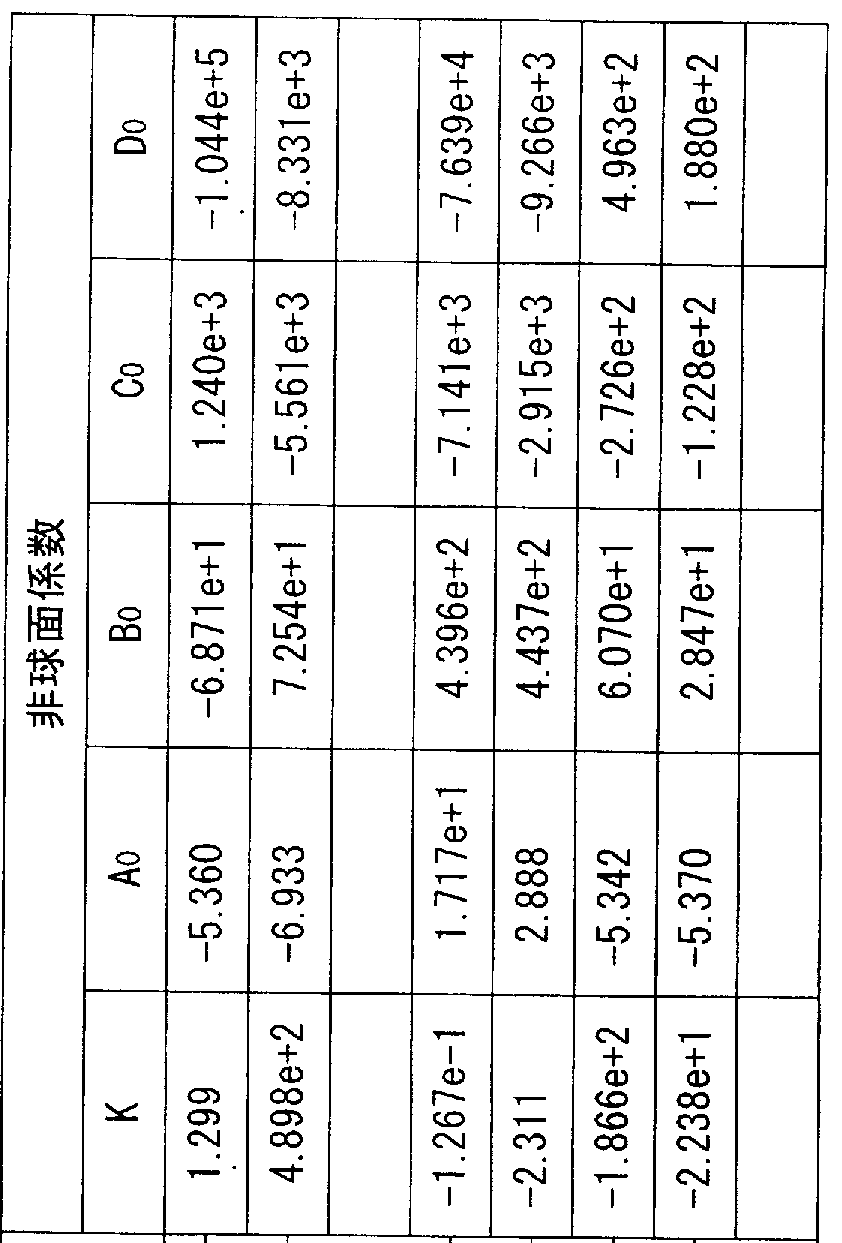
焦点距離 f = 1.00 mm 0.65 mm Fナンバー Fno = 3.4
-2.71 mm 像高 2Y = 1.28 mm
—2.59 ran

第 1レンズ Ll、及び第 3レンズ L3の素材に ゼォネックス E48Rを用い、第 2レンズ L2
の素材に、フルオレン系ポリエステル EP-4000 (EP-4000は、三菱ガス化学株式会社 の商品番号である。 )を用いた。
(A)第 1レンズ L1の物体側曲率半径 rは、 r =0.356 mmである。
1 1
(B)第 1レンズ L1の像側曲率半径 rは、 r =-17.782 mmである。
2 2
(C)第 2レンズ L2と第 3レンズ L3との光軸上の間隔 Dは、 D = 0.1000 mmである。
(D)光学長 Lは、 L= 1.1208 mmである。
(E)像高(有効画面対角線長) 2Yは、 2Y=2 X 0.64= 1.28 mmである。
(F)第 1レンズ L1の焦点距離 fは、 f =0.66 mmである。
1 1
よって、
(2-1) I r /r | = | 0.356/-17.782 | =0.020、
1 2
(2-2) D /f =0.1000/1.00 = 0.1000、
(2-3) L/2Y = 1.121/1.28 = 0.8756、
(2-4) f /f =0.66/1.00 = 0.66、
1
となるので、実施例 5のレンズ系は、以下の条件式 (2-1)から条件式 (2-4)までのいず れをも満たしている。
[0143] 0.01 < I r /r | < 0.05 (2—1)
1 2
0.05 < D /f ≤ 0.1 (2-2)
0.6 < L/2Y < 0.9 (2-3)
0.5 < f /f < 0.7 (2-4)
1
以後、第 2の発明における条件式とは上記 (2-1)から (2-4)までの 4つの式を指すも のとする。
[0144] 表 5に示すとおり、絞り S2は、第 1レンズ L1と第 2レンズ L2の間の位置に設けられてい る。すなわち、絞り面は平面であるので、表 5に r =∞と示してあることから、面 の位
3 3 置に絞り S2が配置されていることを示している。また、 Fナンバーは、 3.4である。
[0145] 図 19に実施例 5の撮像レンズの断面図を示す。焦点距離 1.00 mmに対するバックフ オーカスは 0.389 mmと、十分な長さに確保できている。
[0146] 図 20に示す歪曲収差曲線 120、図 21に示す非点収差曲線 (メリジォナル面に対す る収差曲線 122及びサジタル面に対する収差曲線 124)、図 22に示す色'球面収差曲
線 (C線に対する収差曲線 126、 d線に対する収差曲線 128、 e線に対する収差曲線 13
0、 F線に対する収差曲線 132及び g線に対する収差曲線 134)について、それぞれグ ラフによって示してある。
[0147] 図 20及び図 21の収差曲線の縦軸は、像高を光軸からの距離の何%であるかで示し ている。図 24及び図 25中で、 100%は 0.640 mmに対応している。また、図 22の収差曲 線の縦軸は、入射高 h(Fナンバー)を示しており、最大が 3.4に対応する。図 22の横軸 は、収差の大きさを示している。
[0148] 歪曲収差は、像高 60% (像高 0.384mm)位置において収差量の絶対値が 0.3310% と最大になっており、像高 0.640 mm以下の範囲で収差量の絶対値が 0.3310%以内 に収まっている。
[0149] 非点収差は、像高 100% (像高 0.640 mm)位置においてサジタル面における収差量 の絶対値が 0.0196 mmと最大になっており、また、像高 0.640 mm以下の範囲で収差 量の絶対値が 0.0196 mm以内に収まっている。
[0150] 色.球面収差は、入射高 hの 30%において g線に対する収差曲線 134の絶対値が 0.
0114 mmと最大になっており、収差量の絶対値が 0.0114 mm以内に収まっている。 実施例 6
[0151] 第 1レンズ Ll、及び第 3レンズ L3の素材に、ゼォネックス E48Rを用い、第 2レンズ L2 の素材に、ポリカーボネートを用いた。
(A)第 1レンズ L1の物体側曲率半径 rは、 r =0.3566 mmである。
1 1
(B)第 1レンズ L1の像側曲率半径 rは、 r =-17.782 mmである。
2 2
(C)第 2レンズ L2と第 3レンズ L3との光軸上の間隔 Dは、 D = 0.1000 mmである。
(D)光学長 Lは、 L= 1.119 mmである。
(E)像高(有効画面対角線長) 2Yは、 2Y=2 X 0.64= 1.28 mmである。
(F)第 1レンズ L1の焦点距離 fは、 f =0.66 mmである。
1 1
よって、
(2-1) I r /r | = | 0.356/-17.782 | =0.020、
1 2
(2-2) D /f =0.100/1.00 = 0.100、
(2-3) L/2Y = 1.119/1.28 = 0.874、
(2-4) f /f =0.66/1.00 = 0.66、
1
となるので、実施例 6のレンズ系は、以下の条件式 (2-1)から条件式 (2-4)までのいず れをも満たしている。
[0152] 0.01 < I r /r | < 0.05 (2—1)
1 2
0.05 < D /f ≤ 0.1 (2-2)
0.6 < L/2Y < 0.9 (2-3)
0.5 < f /f < 0.7 (2-4)
1
以後、第 2の発明における条件式とは上記 (2-1)から (2-4)までの 4つの式を指すも のとする。
[0153] 表 6に示すとおり、絞り S2は、第 1レンズ L1と第 2レンズ L2の間の位置に設けられてい る。すなわち、絞り面は平面であるので、表 6に r =∞と示してあることから、面 の位
3 3 置に絞り S2が配置されていることを示している。また、 Fナンバーは、 3.4である。
[0154] 図 23に実施例 6の撮像レンズの断面図を示す。焦点距離 1.00 mmに対するバックフ オーカスは 0.386 mmと、十分な長さに確保できている。
[0155] 図 24に示す歪曲収差曲線 136、図 25に示す非点収差曲線 (メリジォナル面に対す る収差曲線 138及びサジタル面に対する収差曲線 140)、図 26に示す色'球面収差曲 線 (C線に対する収差曲線 142、 d線に対する収差曲線 144、 e線に対する収差曲線 14
6、 F線に対する収差曲線 148及び g線に対する収差曲線 150)について、それぞれグ ラフによって示してある。
[0156] 図 24及び図 25の収差曲線の縦軸は、像高を光軸からの距離の何%であるかで示し ている。図 24及び図 25中で、 100%は 0.640 mmに対応している。また、図 26の収差曲 線の縦軸は、入射高 h(Fナンバー)を示しており、最大が 3.4に対応する。図 26の横軸 は、収差の大きさを示している。
[0157] 歪曲収差は、像高 60% (像高 0.384mm)位置において収差量の絶対値が 0.2936% と最大になっており、像高 0.640 mm以下の範囲で収差量の絶対値が 0.2963%以内 に収まっている。
[0158] 非点収差は、像高 100% (像高 0.640 mm)位置においてサジタル面における収差量 の絶対値が 0.0221 mmと最大になっており、また、像高 0.640 mm以下の範囲で収差
量の絶対値が 0.0221 mm以内に収まっている。
[0159] 色.球面収差は、入射高 hの 30%において g線に対する収差曲線 150の絶対値が 0.
0129 mmと最大になっており、収差量の絶対値が 0.0129 mm以内に収まっている。 実施例 7
[0160] 第 1レンズ Ll、及び第 3レンズ L3の素材に、ゼォネックス E48Rを用い、第 2レンズ L2 の素材に、ポリカーボネートを用いた。
(A)第 1レンズ L1の物体側曲率半径 rは、 r =0.356 mmである。
1 1
(B)第 1レンズ L1の像側曲率半径 rは、 r =-8.887 mmである。
2 2
(C)第 2レンズ L2と第 3レンズ L3との光軸上の間隔 Dは、 D = 0.080 mmである。
(D)光学長 Lは、 L= 1.092 mmである。
(E)像高(有効画面対角線長) 2Yは、 2Y=2 X 0.64= 1.28 mmである。
(F)第 1レンズ L1の焦点距離 fは、 f =0.65 mmである。
1 1
よって、
(2-1) I r /r | = | 0.356/— 8.887 | =0.04、
1 2
(2-2) D /f =0.080/1.00 = 0.08、
(2-3) L/2Y = 1.092/1.28 = 0.8531、
(2-4) f /f =0.65/1.00 = 0.65、
1
となるので、実施例 7のレンズ系は、以下の条件式 (2-1)から条件式 (2-4)までのいず れをも満たしている。
[0161] 0.01 < I r /r | < 0.05 (2—1)
1 2
0.05 < D /f ≤ 0.1 (2-2)
0.6 < L/2Y < 0.9 (2-3)
0.5 < f /f < 0.7 (2-4)
1
以後、第 2の発明における条件式とは上記 (2-1)から (2-4)までの 4つの式を指すも のとする。
[0162] 表 7に示すとおり、絞り S2は、第 1レンズ L1と第 2レンズ L2の間の位置に設けられてい る。すなわち、絞り面は平面であるので、表 7に r =∞と示してあることから、面 の位
3 3 置に絞り S2が配置されていることを示している。また、 Fナンバーは、 3.4である。
[0163] 図 27に実施例 7の撮像レンズの断面図を示す。焦点距離 1.00 mmに対するバックフ オーカスは 0.381 mmと、十分な長さに確保できている。
[0164] 図 28に示す歪曲収差曲線 152、図 29に示す非点収差曲線 (メリジォナル面に対す る収差曲線 154及びサジタル面に対する収差曲線 156)、図 30に示す色'球面収差曲 線 (C線に対する収差曲線 158、 d線に対する収差曲線 160、 e線に対する収差曲線 16
2、 F線に対する収差曲線 164及び g線に対する収差曲線 166)について、それぞれグ ラフによって示してある。
[0165] 図 28及び図 29の収差曲線の縦軸は、像高を光軸からの距離の何%であるかで示し ている。図 28及び図 29中で、 100%は 0.640 mmに対応している。また、図 30の収差曲 線の縦軸は、入射高 h(Fナンバー)を示しており、最大が 3.4に対応する。図 30の横軸 は、収差の大きさを示している。
[0166] 歪曲収差は、像高 80% (像高 0.512mm)位置において収差量の絶対値が 0.3963% と最大になっており、像高 0.640 mm以下の範囲で収差量の絶対値が 0.3963%以内 に収まっている。
[0167] 非点収差は、像高 100% (像高 0.640 mm)位置においてメリジォナル面における収 差量の絶対値が 0.0579 mmと最大になっており、また、像高 0.640 mm以下の範囲で 収差量の絶対値が 0.0579 mm以内に収まっている。
[0168] 色.球面収差は、入射高 hの 30%において g線に対する収差曲線 166の絶対値が 0.
0154 mmと最大になっており、収差量の絶対値が 0.0154 mm以内に収まっている。 実施例 8
[0169] 第 1レンズ Ll、及び第 3レンズ L3の素材に、ゼォネックス E48Rを用い、第 2レンズ L2 の素材に、ポリカーボネートを用いた。
(A)第 1レンズ L1の物体側曲率半径 rは、 r =0.356 mmである。
1 1
(B)第 1レンズ L1の像側曲率半径 rは、 r =-8.887 mmである。
2 2
(C)第 2レンズ L2と第 3レンズ L3との光軸上の間隔 Dは、 D = 0.0511mmである。
(D)光学長 Lは、 L= 1.104 mmである。
(E)像高(有効画面対角線長) 2Yは、 2Y=2 X 0.64= 1.28 mmである。
(F)第 1レンズ L1の焦点距離 fは、 f =0.65 mmである。
よって、
(2-1) I r /r | = | 0.356/— 8.887 | =0.04、
1 2
(2-2) D /f =0.0511/1.00 = 0.0511、
(2-3) L/2Y = 1.104/1.28 = 0.8627、
(2-4) f /f =0.65/1.00 = 0.65、
1
となるので、実施例 8のレンズ系は、以下の条件式 (2-1)から条件式 (2-4)までのいず れをも満たしている。
[0170] 0.01 < I r /r | < 0.05 (2—1)
1 2
0.05 < D /f ≤ 0.1 (2-2)
0.6 < L/2Y < 0.9 (2-3)
0.5 < f /f < 0.7 (2-4)
1
以後、第 2の発明における条件式とは上記 (2-1)から (2-4)までの 4つの式を指すも のとする。
[0171] 表 8に示すとおり、絞り S2は、第 1レンズ L1と第 2レンズ L2の間の位置に設けられてい る。すなわち、絞り面は平面であるので、表 8に r =∞と示してあることから、面 の位
3 3 置に絞り S2が配置されていることを示している。また、 Fナンバーは、 3.4である。
[0172] 図 31に実施例 8の撮像レンズの断面図を示す。焦点距離 1.00 mmに対するバックフ オーカスは 0.422 mmと、十分な長さに確保できている。
[0173] 図 32に示す歪曲収差曲線 168、図 33に示す非点収差曲線 (メリジォナル面に対す る収差曲線 170及びサジタル面に対する収差曲線 172)、図 34に示す色,球面収差曲 線 (C線に対する収差曲線 174、 d線に対する収差曲線 176、 e線に対する収差曲線 17 8、 F線に対する収差曲線 180及び g線に対する収差曲線 182)について、それぞれグ ラフによって示してある。
[0174] 図 32及び図 33の収差曲線の縦軸は、像高を光軸からの距離の何%であるかで示し ている。図 32及び図 37中で、 100%は 0.640 mmに対応している。また、図 34の収差曲 線の縦軸は、入射高 h(Fナンバー)を示しており、最大が 3.4に対応する。図 34の横軸 は、収差の大きさを示している。
[0175] 歪曲収差は、像高 100% (像高 0.640mm)位置において収差量の絶対値が 0.3489
%と最大になっており、像高 0.640 mm以下の範囲で収差量の絶対値が 0.3489%以 内に収まっている。
[0176] 非点収差は、像高 100% (像高 0.640 mm)位置においてメリジォナル面における収 差量の絶対値が 0.0344 mmと最大になっており、また、像高 0.640 mm以下の範囲で 収差量の絶対値が 0.0344 mm以内に収まっている。
[0177] 色.球面収差は、入射高 hの 30%において g線に対する収差曲線 182の絶対値が 0.
0154 mmと最大になっており、収差量の絶対値が 0.0154 mm以内に収まっている。
[0178] 第 1及び第 2の発明の撮像レンズの説明から明らかなように、撮像レンズの各構成レ ンズを条件式 (1-1)から (1-4)及び条件式 (2-1)から (2-4)を満たすように設計すること で、この発明が解決しょうとする課題が解決する。すなわち、諸収差が良好に補正さ れ、十分なバックフォーカスが得られかつ光学長が短く保たれた撮像レンズが得られ る。
[0179] なお、上述した実施例において第 1レンズ L1及び第 3レンズ L3にはシクロォレフィン 系プラスチックを、第 2レンズ L2にはポリカーボネートあるいはフルオレン系ポリエステ ルと 、うプラスチック素材を用いた力 実施例に掲げた以外のプラスチック材料はもと より、プラスチック素材でなくとも、例えば、モールドガラス等でも、実施例等で説明し た諸条件を満たす素材であれば、ガラスその他の材料を用いることができることは言 うまでもない。
産業上の利用可能性
[0180] 以上、説明したように、第 1及び第 2の発明の撮像レンズによれば、諸収差が良好に 補正され、光学長が短いにもかかわらず、良好な画像が得られ、ノ ックフォーカスも 十分に確保できる。
[0181] 以上説明したことから、この発明の撮像レンズは、携帯電話機、パーソナルコンビュ ータあるいはデジタルカメラに内蔵するカメラ用レンズとしての利用はもとより、携帯情 報端末(PDA: personal digital assistants)に内蔵するカメラ用レンズ、画像認識機能 を具えた玩具に内蔵するカメラ用レンズ、監視、検査あるいは防犯機器等に内蔵す るカメラ用レンズとして適用しても好適である。
Claims
請求の範囲
矩形受光面における対角線の長さ力 ¾Yである固体撮像素子を具える撮像装置に 搭載される撮像レンズであって、
開口絞り Sl、第 1レンズ Ll、第 2レンズ L2及び第 3レンズ L3を具え、
物体側力も像側に向力つて、該開口絞り Sl、該第 1レンズ Ll、該第 2レンズ L2及び 該第 3レンズ L3の順に配列されて構成され、
該第 1レンズ L1は、物体側及び像側に凸面を向けた正の屈折力を有するレンズで あり、
該第 2レンズ L2は、像側に凸面を向けたメニスカス形状の負の屈折力を有するレン ズであり、
該第 3レンズ L3は、物体側に凸面を向けたメニスカス形状の負の屈折力を有するレ ンズであって、
該第 1レンズ L1の両面が非球面、かつ該第 2レンズ L2の両面が非球面、かつ該第 3 レンズ L3の両面が非球面であり、
以下の条件を満たすことを特徴とする撮像レンズ。
0.01 < I r /r I < 0.05 (1—1)
2 3
0.05 < D /f ≤ 0.1 (1-2)
0.6 < L/2Y < 0.9 (1-3)
0.5 < f /f < 0.7 (1-4)
1
ただし、
f :撮像レンズの合成焦点距離
r :第 1レンズ L1の物体側面の光軸近傍における曲率半径 (光軸上曲率半径)
2
r :第 1レンズ L1の像側面の光軸近傍における曲率半径 (光軸上曲率半径)
3
D:第 2レンズ L2と第 3レンズ L3との光軸上の間隔
L :第 1レンズ L1の物体側面力 像面までの光軸上の空気中の距離 (光学長) 2Y:撮像レンズの像面に設置される固体撮像素子の矩形受光面における対角線 の長さ
f :第 1レンズ L1の焦点距離
[2] 矩形受光面における対角線の長さが 2Yである固体撮像素子を具える撮像装置に 搭載される撮像レンズであって、
第 1レンズ Ll、開口絞り S2、第 2レンズ L2及び第 3レンズ L3を具え、
物体側力も像側に向力つて、該第 1レンズ Ll、該開口絞り S2、該第 2レンズ L2及び 該第 3レンズ L3の順に配列されて構成され、
該第 1レンズ L1は、物体側及び像側に凸面を向けた正の屈折力を有するレンズで あり、
該第 2レンズ L2は、像側に凸面を向けたメニスカス形状の負の屈折力を有するレン ズであり、
該第 3レンズ L3は、物体側に凸面を向けたメニスカス形状の負の屈折力を有するレ ンズであって、
該第 1レンズ L1の両面が非球面、かつ該第 2レンズ L2の両面が非球面、かつ該第 3 レンズ L3の両面が非球面であり、
以下の条件を満たすことを特徴とする撮像レンズ。
0.01 < I r /r I < 0.05 (2—1)
1 2
0.05 < D /f ≤ 0.1 (2-2)
0.6 < L/2Y < 0.9 (2-3)
0.5 < f /f < 0.7 (2-4)
1
ただし、
f :撮像レンズの合成焦点距離
r :第 1レンズ L1の物体側面の光軸近傍における曲率半径 (光軸上曲率半径)
1
r :第 1レンズ L1の像側面の光軸近傍における曲率半径 (光軸上曲率半径)
2
D:第 2レンズ L2と第 3レンズ L3との光軸上の間隔
L :第 1レンズ L1の物体側面力 像面までの光軸上の空気中の距離 (光学長) 2Y:撮像レンズの像面に設置される固体撮像素子の矩形受光面における対角線 の長さ
f :第 1レンズ L1の焦点距離
1
[3] 請求項 1又は 2に記載の撮像レンズであって、前記第 2レンズ L2の素材の屈折率が
、前記第 1レンズ LI及び前記第 3レンズ L3の素材の屈折率よりも高ぐ前記第 2レンズ L2の素材のアッベ数が、前記第 1レンズ L1及び前記第 3レンズ L3の素材のアッベ数よ りも小さ!/、ことを特徴とする撮像レンズ。
[4] 請求項 1又は 2に記載の撮像レンズであって、該撮像レンズを構成する前記第 1レン ズ L1及び前記第 3レンズ L3が、シクロォレフイン系プラスチックを素材として形成した レンズであり、
前記第 2レンズ L2が、フルオレン系ポリエステルを素材として形成したレンズである ことを特徴とする撮像レンズ。
[5] 請求項 1又は 2に記載の撮像レンズであって、該撮像レンズを構成する前記第 1レン ズ L1及び前記第 3レンズ L3が、シクロォレフイン系プラスチックを素材として形成した レンズであり、
前記第 2レンズ L2が、ポリカーボネートを素材として形成したレンズであることを特徴 とする撮像レンズ。
Priority Applications (3)
| Application Number | Priority Date | Filing Date | Title |
|---|---|---|---|
| EP06781989A EP1804101B1 (en) | 2005-10-03 | 2006-07-31 | Imaging lens |
| DE602006007670T DE602006007670D1 (de) | 2005-10-03 | 2006-07-31 | Aufnahmelinse |
| US11/597,795 US7675692B2 (en) | 2005-10-03 | 2006-07-31 | Pickup lens |
Applications Claiming Priority (2)
| Application Number | Priority Date | Filing Date | Title |
|---|---|---|---|
| JP2005-290333 | 2005-10-03 | ||
| JP2005290333A JP3816093B1 (ja) | 2005-10-03 | 2005-10-03 | 撮像レンズ |
Publications (1)
| Publication Number | Publication Date |
|---|---|
| WO2007039980A1 true WO2007039980A1 (ja) | 2007-04-12 |
Family
ID=36991065
Family Applications (1)
| Application Number | Title | Priority Date | Filing Date |
|---|---|---|---|
| PCT/JP2006/315111 WO2007039980A1 (ja) | 2005-10-03 | 2006-07-31 | 撮像レンズ |
Country Status (7)
| Country | Link |
|---|---|
| US (1) | US7675692B2 (ja) |
| EP (1) | EP1804101B1 (ja) |
| JP (1) | JP3816093B1 (ja) |
| KR (1) | KR100791642B1 (ja) |
| CN (1) | CN100416331C (ja) |
| DE (1) | DE602006007670D1 (ja) |
| WO (1) | WO2007039980A1 (ja) |
Cited By (2)
| Publication number | Priority date | Publication date | Assignee | Title |
|---|---|---|---|---|
| US8023203B2 (en) | 2009-06-19 | 2011-09-20 | E-Pin Optical Industry Co., Ltd. | Miniature three-piece optical imaging lens with short back focal length |
| US8339715B2 (en) | 2010-06-30 | 2012-12-25 | E-Pin Optical Industry Co., Ltd. | Three-piece optical pickup lens |
Families Citing this family (27)
| Publication number | Priority date | Publication date | Assignee | Title |
|---|---|---|---|---|
| JP2007156277A (ja) * | 2005-12-07 | 2007-06-21 | Kyocera Corp | 撮像レンズ、光学モジュール、および携帯端末 |
| JP3816095B1 (ja) * | 2005-12-16 | 2006-08-30 | マイルストーン株式会社 | 撮像レンズ |
| JP2008180870A (ja) * | 2007-01-24 | 2008-08-07 | Opt Design:Kk | 小型レンズ |
| JP5037963B2 (ja) * | 2007-02-09 | 2012-10-03 | 富士フイルム株式会社 | 撮像レンズ |
| TWI354820B (en) * | 2007-08-14 | 2011-12-21 | Largan Precision Co Ltd | Optical lens system for taking image |
| KR100973290B1 (ko) * | 2008-03-13 | 2010-07-30 | 삼성테크윈 주식회사 | 카메라용 결상 광학계 |
| US8094383B2 (en) * | 2008-04-10 | 2012-01-10 | E-Pin Optical Industry Co., Ltd. | Optical imaging lens |
| JP4505765B2 (ja) | 2008-04-23 | 2010-07-21 | ソニー株式会社 | 撮像レンズ及び撮像装置 |
| WO2010024214A1 (ja) * | 2008-08-29 | 2010-03-04 | コニカミノルタオプト株式会社 | 撮像光学系及び撮像装置 |
| KR101499970B1 (ko) * | 2008-10-14 | 2015-03-06 | 엘지이노텍 주식회사 | 촬상 렌즈 및 이를 포함하는 카메라 모듈 |
| KR101499971B1 (ko) * | 2008-10-14 | 2015-03-06 | 엘지이노텍 주식회사 | 촬상 렌즈 및 이를 포함하는 카메라 모듈 |
| JP5308778B2 (ja) * | 2008-11-10 | 2013-10-09 | オリンパス株式会社 | 広角光学系及びそれを用いた撮像装置 |
| JP5308915B2 (ja) * | 2009-05-28 | 2013-10-09 | 株式会社オプトロジック | 撮像レンズ |
| CN102193168B (zh) * | 2010-03-04 | 2012-08-29 | 大立光电股份有限公司 | 摄影透镜系统 |
| CN102736226B (zh) * | 2010-03-04 | 2014-06-04 | 大立光电股份有限公司 | 摄影透镜系统 |
| TWI407142B (zh) * | 2010-03-09 | 2013-09-01 | Largan Precision Co Ltd | 攝像透鏡組 |
| CN102445746B (zh) * | 2010-10-11 | 2014-05-21 | 大立光电股份有限公司 | 光学摄像镜头 |
| KR101222839B1 (ko) * | 2010-10-22 | 2013-01-30 | 주식회사 코렌 | 촬영 렌즈 광학계 |
| TWI443367B (zh) * | 2012-03-09 | 2014-07-01 | Largan Precision Co Ltd | 拾像鏡片系統 |
| JP6099840B2 (ja) | 2014-10-17 | 2017-03-22 | 浙江舜宇光学有限公司 | 撮像レンズ |
| CN105700113A (zh) * | 2014-11-28 | 2016-06-22 | 鸿富锦精密工业(深圳)有限公司 | 成像镜头 |
| TWI546562B (zh) * | 2014-12-04 | 2016-08-21 | 先進光電科技股份有限公司 | 光學成像系統(一) |
| KR20160069087A (ko) * | 2014-12-05 | 2016-06-16 | 에이에이씨 어쿠스틱 테크놀로지스 (심천) 컴퍼니 리미티드 | 소형 촬영 렌즈계 |
| US9548288B1 (en) * | 2014-12-22 | 2017-01-17 | Apple Inc. | Integrated circuit die decoupling system with reduced inductance |
| TWI572888B (zh) * | 2015-01-21 | 2017-03-01 | 先進光電科技股份有限公司 | 光學成像系統(一) |
| US9455189B1 (en) | 2015-06-14 | 2016-09-27 | Darryl G. Walker | Package including a plurality of stacked semiconductor devices including a capacitance enhanced through via and method of manufacture |
| CN111853699B (zh) * | 2020-08-28 | 2021-02-12 | 广东烨嘉光电科技股份有限公司 | 一种大孔径的三片式透镜光学镜头 |
Citations (3)
| Publication number | Priority date | Publication date | Assignee | Title |
|---|---|---|---|---|
| JP2005017440A (ja) * | 2003-06-24 | 2005-01-20 | Fujinon Corp | 結像レンズ |
| JP2005227755A (ja) * | 2004-01-13 | 2005-08-25 | Miyota Kk | 小型結像レンズ |
| JP2005309210A (ja) * | 2004-04-23 | 2005-11-04 | Enplas Corp | 撮像レンズ |
Family Cites Families (22)
| Publication number | Priority date | Publication date | Assignee | Title |
|---|---|---|---|---|
| FR2334358A1 (fr) * | 1975-12-12 | 1977-07-08 | Sogeras | Nouveaux medicaments derives de l'indole |
| JP4173210B2 (ja) * | 1997-04-30 | 2008-10-29 | フジノン株式会社 | 結像レンズ |
| JP3925748B2 (ja) * | 1997-04-30 | 2007-06-06 | フジノン株式会社 | 小型レンズ |
| JP3545654B2 (ja) * | 1999-09-06 | 2004-07-21 | 株式会社エンプラス | 撮像レンズ |
| JP3485503B2 (ja) * | 1999-09-09 | 2004-01-13 | 株式会社エンプラス | 撮像レンズ |
| JP3749128B2 (ja) | 2001-01-24 | 2006-02-22 | 株式会社エンプラス | 撮像レンズ |
| JP3749130B2 (ja) | 2001-02-15 | 2006-02-22 | 株式会社エンプラス | 撮像レンズ |
| JP4109857B2 (ja) | 2001-11-12 | 2008-07-02 | フジノン株式会社 | フロントシャッタ方式の単焦点レンズ |
| JP3810058B2 (ja) * | 2001-11-16 | 2006-08-16 | フジノン株式会社 | 簡易構成単焦点レンズ |
| EP1348990B1 (en) | 2002-03-25 | 2006-01-11 | Konica Corporation | Objective composed of three lenses |
| JP3567327B2 (ja) * | 2002-05-08 | 2004-09-22 | 富士写真光機株式会社 | 撮像レンズ |
| JP2004212467A (ja) * | 2002-12-27 | 2004-07-29 | Nidec Copal Corp | 撮影レンズ |
| JP2004226487A (ja) | 2003-01-20 | 2004-08-12 | Seiko Epson Corp | 撮像レンズ |
| JP3717489B2 (ja) | 2003-03-31 | 2005-11-16 | フジノン株式会社 | 単焦点レンズ |
| JP3717488B2 (ja) | 2003-03-31 | 2005-11-16 | フジノン株式会社 | 単焦点レンズ |
| JP4156961B2 (ja) | 2003-03-31 | 2008-09-24 | フジノン株式会社 | 単焦点レンズ |
| JP2005004045A (ja) * | 2003-06-13 | 2005-01-06 | Enplas Corp | 撮像レンズ |
| SG140461A1 (en) * | 2003-07-11 | 2008-03-28 | Konica Minolta Opto Inc | Image pick-up lens, image pick-up unit, and mobile terminal provided with this image pick-up unit |
| JP3521332B1 (ja) * | 2003-08-06 | 2004-04-19 | マイルストーン株式会社 | 撮像レンズ |
| JP2005292235A (ja) | 2004-03-31 | 2005-10-20 | Seiko Precision Inc | 撮像レンズ |
| JP2006098429A (ja) * | 2004-09-28 | 2006-04-13 | Konica Minolta Opto Inc | 撮像レンズ |
| JP2007003768A (ja) * | 2005-06-23 | 2007-01-11 | Konica Minolta Opto Inc | 撮影レンズ |
-
2005
- 2005-10-03 JP JP2005290333A patent/JP3816093B1/ja not_active Expired - Fee Related
- 2005-12-14 CN CNB2005101296282A patent/CN100416331C/zh active Active
-
2006
- 2006-07-31 EP EP06781989A patent/EP1804101B1/en not_active Not-in-force
- 2006-07-31 DE DE602006007670T patent/DE602006007670D1/de not_active Expired - Fee Related
- 2006-07-31 US US11/597,795 patent/US7675692B2/en active Active
- 2006-07-31 WO PCT/JP2006/315111 patent/WO2007039980A1/ja active Application Filing
- 2006-07-31 KR KR1020067026661A patent/KR100791642B1/ko not_active IP Right Cessation
Patent Citations (3)
| Publication number | Priority date | Publication date | Assignee | Title |
|---|---|---|---|---|
| JP2005017440A (ja) * | 2003-06-24 | 2005-01-20 | Fujinon Corp | 結像レンズ |
| JP2005227755A (ja) * | 2004-01-13 | 2005-08-25 | Miyota Kk | 小型結像レンズ |
| JP2005309210A (ja) * | 2004-04-23 | 2005-11-04 | Enplas Corp | 撮像レンズ |
Non-Patent Citations (1)
| Title |
|---|
| See also references of EP1804101A4 * |
Cited By (2)
| Publication number | Priority date | Publication date | Assignee | Title |
|---|---|---|---|---|
| US8023203B2 (en) | 2009-06-19 | 2011-09-20 | E-Pin Optical Industry Co., Ltd. | Miniature three-piece optical imaging lens with short back focal length |
| US8339715B2 (en) | 2010-06-30 | 2012-12-25 | E-Pin Optical Industry Co., Ltd. | Three-piece optical pickup lens |
Also Published As
| Publication number | Publication date |
|---|---|
| CN1945372A (zh) | 2007-04-11 |
| US20090190236A1 (en) | 2009-07-30 |
| EP1804101A1 (en) | 2007-07-04 |
| JP3816093B1 (ja) | 2006-08-30 |
| CN100416331C (zh) | 2008-09-03 |
| EP1804101A4 (en) | 2007-11-07 |
| KR100791642B1 (ko) | 2008-01-04 |
| DE602006007670D1 (de) | 2009-08-20 |
| US7675692B2 (en) | 2010-03-09 |
| EP1804101B1 (en) | 2009-07-08 |
| KR20070057087A (ko) | 2007-06-04 |
| JP2008180744A (ja) | 2008-08-07 |
Similar Documents
| Publication | Publication Date | Title |
|---|---|---|
| JP3816093B1 (ja) | 撮像レンズ | |
| JP3816095B1 (ja) | 撮像レンズ | |
| CN209102994U (zh) | 摄像镜头 | |
| CN211506003U (zh) | 摄像镜头 | |
| TWI390244B (zh) | 攝影鏡頭 | |
| JP3659966B1 (ja) | 撮像レンズ | |
| JP3521332B1 (ja) | 撮像レンズ | |
| CN203311088U (zh) | 摄像镜头 | |
| KR100555110B1 (ko) | 촬상 렌즈 | |
| JP3963943B1 (ja) | 撮像レンズ | |
| CN203365784U (zh) | 摄像镜头 | |
| US7508601B2 (en) | Imaging lens | |
| EP1387199A1 (en) | Image pickup lens | |
| JP4781487B1 (ja) | 撮像レンズ | |
| JP2014160154A (ja) | 撮像レンズ | |
| JP2008233221A (ja) | 撮影レンズ | |
| JP3452919B1 (ja) | 撮像用レンズ | |
| KR100791641B1 (ko) | 촬상렌즈 | |
| JP4041521B1 (ja) | 撮像レンズ |
Legal Events
| Date | Code | Title | Description |
|---|---|---|---|
| WWE | Wipo information: entry into national phase |
Ref document number: 11597795 Country of ref document: US |
|
| WWE | Wipo information: entry into national phase |
Ref document number: 2006781989 Country of ref document: EP |
|
| WWE | Wipo information: entry into national phase |
Ref document number: 1020067026661 Country of ref document: KR |
|
| WWP | Wipo information: published in national office |
Ref document number: 2006781989 Country of ref document: EP |
|
| NENP | Non-entry into the national phase |
Ref country code: DE |
|
| NENP | Non-entry into the national phase |
Ref country code: JP |