WO2006080428A1 - レジストパターン形成方法 - Google Patents
レジストパターン形成方法 Download PDFInfo
- Publication number
- WO2006080428A1 WO2006080428A1 PCT/JP2006/301297 JP2006301297W WO2006080428A1 WO 2006080428 A1 WO2006080428 A1 WO 2006080428A1 JP 2006301297 W JP2006301297 W JP 2006301297W WO 2006080428 A1 WO2006080428 A1 WO 2006080428A1
- Authority
- WO
- WIPO (PCT)
- Prior art keywords
- resist pattern
- supercritical
- crosslinking agent
- group
- resist
- Prior art date
Links
- 238000000034 method Methods 0.000 title claims abstract description 57
- 239000003431 cross linking reagent Substances 0.000 claims abstract description 223
- 239000012530 fluid Substances 0.000 claims abstract description 83
- 239000007788 liquid Substances 0.000 claims abstract description 76
- 239000000203 mixture Substances 0.000 claims abstract description 70
- 239000000758 substrate Substances 0.000 claims abstract description 28
- 238000001459 lithography Methods 0.000 claims abstract description 4
- 238000012545 processing Methods 0.000 claims description 95
- 239000002253 acid Substances 0.000 claims description 60
- 239000002243 precursor Substances 0.000 claims description 49
- 239000000126 substance Substances 0.000 claims description 35
- -1 fullerene compound Chemical class 0.000 claims description 34
- 150000001875 compounds Chemical class 0.000 claims description 33
- XSQUKJJJFZCRTK-UHFFFAOYSA-N Urea Chemical compound NC(N)=O XSQUKJJJFZCRTK-UHFFFAOYSA-N 0.000 claims description 21
- 125000000217 alkyl group Chemical group 0.000 claims description 17
- 238000011161 development Methods 0.000 claims description 16
- 239000004202 carbamide Substances 0.000 claims description 15
- 125000004432 carbon atom Chemical group C* 0.000 claims description 14
- VPVSTMAPERLKKM-UHFFFAOYSA-N glycoluril Chemical compound N1C(=O)NC2NC(=O)NC21 VPVSTMAPERLKKM-UHFFFAOYSA-N 0.000 claims description 12
- 229920000877 Melamine resin Polymers 0.000 claims description 11
- JDSHMPZPIAZGSV-UHFFFAOYSA-N melamine Chemical compound NC1=NC(N)=NC(N)=N1 JDSHMPZPIAZGSV-UHFFFAOYSA-N 0.000 claims description 11
- 125000002924 primary amino group Chemical group [H]N([H])* 0.000 claims description 8
- 125000000391 vinyl group Chemical group [H]C([*])=C([H])[H] 0.000 claims description 7
- 239000012298 atmosphere Substances 0.000 claims description 6
- 229910003472 fullerene Inorganic materials 0.000 claims description 5
- 229920002554 vinyl polymer Polymers 0.000 claims description 5
- 206010034972 Photosensitivity reaction Diseases 0.000 claims description 4
- 230000036211 photosensitivity Effects 0.000 claims description 4
- 244000309464 bull Species 0.000 claims description 2
- 229920001289 polyvinyl ether Polymers 0.000 claims description 2
- 238000001704 evaporation Methods 0.000 claims 1
- 230000008016 vaporization Effects 0.000 claims 1
- 238000005530 etching Methods 0.000 abstract description 59
- 239000000243 solution Substances 0.000 description 38
- 125000004435 hydrogen atom Chemical group [H]* 0.000 description 36
- 125000002887 hydroxy group Chemical group [H]O* 0.000 description 33
- CURLTUGMZLYLDI-UHFFFAOYSA-N Carbon dioxide Chemical compound O=C=O CURLTUGMZLYLDI-UHFFFAOYSA-N 0.000 description 30
- 125000002496 methyl group Chemical group [H]C([H])([H])* 0.000 description 28
- 238000006243 chemical reaction Methods 0.000 description 25
- 238000004090 dissolution Methods 0.000 description 24
- 125000003367 polycyclic group Chemical group 0.000 description 23
- WSFSSNUMVMOOMR-UHFFFAOYSA-N Formaldehyde Chemical compound O=C WSFSSNUMVMOOMR-UHFFFAOYSA-N 0.000 description 22
- 230000002401 inhibitory effect Effects 0.000 description 22
- 238000004132 cross linking Methods 0.000 description 21
- RTZKZFJDLAIYFH-UHFFFAOYSA-N Diethyl ether Chemical compound CCOCC RTZKZFJDLAIYFH-UHFFFAOYSA-N 0.000 description 20
- 229920005989 resin Polymers 0.000 description 19
- 239000011347 resin Substances 0.000 description 19
- 238000010438 heat treatment Methods 0.000 description 16
- 239000001569 carbon dioxide Substances 0.000 description 15
- 229910002092 carbon dioxide Inorganic materials 0.000 description 15
- 235000013877 carbamide Nutrition 0.000 description 14
- 230000018109 developmental process Effects 0.000 description 14
- YXHKONLOYHBTNS-UHFFFAOYSA-N Diazomethane Chemical compound C=[N+]=[N-] YXHKONLOYHBTNS-UHFFFAOYSA-N 0.000 description 13
- LYCAIKOWRPUZTN-UHFFFAOYSA-N Ethylene glycol Chemical compound OCCO LYCAIKOWRPUZTN-UHFFFAOYSA-N 0.000 description 12
- CERQOIWHTDAKMF-UHFFFAOYSA-N Methacrylic acid Chemical compound CC(=C)C(O)=O CERQOIWHTDAKMF-UHFFFAOYSA-N 0.000 description 12
- LZCLXQDLBQLTDK-UHFFFAOYSA-N ethyl 2-hydroxypropanoate Chemical compound CCOC(=O)C(C)O LZCLXQDLBQLTDK-UHFFFAOYSA-N 0.000 description 12
- 239000004971 Cross linker Substances 0.000 description 11
- 230000001476 alcoholic effect Effects 0.000 description 10
- 230000008569 process Effects 0.000 description 10
- LLHKCFNBLRBOGN-UHFFFAOYSA-N propylene glycol methyl ether acetate Chemical compound COCC(C)OC(C)=O LLHKCFNBLRBOGN-UHFFFAOYSA-N 0.000 description 10
- 230000002829 reductive effect Effects 0.000 description 10
- JGTNAGYHADQMCM-UHFFFAOYSA-M 1,1,2,2,3,3,4,4,4-nonafluorobutane-1-sulfonate Chemical compound [O-]S(=O)(=O)C(F)(F)C(F)(F)C(F)(F)C(F)(F)F JGTNAGYHADQMCM-UHFFFAOYSA-M 0.000 description 9
- 230000001965 increasing effect Effects 0.000 description 9
- 239000003960 organic solvent Substances 0.000 description 9
- XLLXMBCBJGATSP-UHFFFAOYSA-N 2-phenylethenol Chemical compound OC=CC1=CC=CC=C1 XLLXMBCBJGATSP-UHFFFAOYSA-N 0.000 description 8
- LFQSCWFLJHTTHZ-UHFFFAOYSA-N Ethanol Chemical compound CCO LFQSCWFLJHTTHZ-UHFFFAOYSA-N 0.000 description 8
- 230000000694 effects Effects 0.000 description 8
- XBWQFDNGNOOMDZ-UHFFFAOYSA-N 1,1,2,2,3,3,3-heptafluoropropane-1-sulfonic acid Chemical compound OS(=O)(=O)C(F)(F)C(F)(F)C(F)(F)F XBWQFDNGNOOMDZ-UHFFFAOYSA-N 0.000 description 7
- ARXJGSRGQADJSQ-UHFFFAOYSA-N 1-methoxypropan-2-ol Chemical compound COCC(C)O ARXJGSRGQADJSQ-UHFFFAOYSA-N 0.000 description 7
- 239000004925 Acrylic resin Substances 0.000 description 7
- 229920000178 Acrylic resin Polymers 0.000 description 7
- XUIMIQQOPSSXEZ-UHFFFAOYSA-N Silicon Chemical compound [Si] XUIMIQQOPSSXEZ-UHFFFAOYSA-N 0.000 description 7
- 239000003513 alkali Substances 0.000 description 7
- 125000003277 amino group Chemical group 0.000 description 7
- 238000010586 diagram Methods 0.000 description 7
- 235000019441 ethanol Nutrition 0.000 description 7
- JESXATFQYMPTNL-UHFFFAOYSA-N mono-hydroxyphenyl-ethylene Natural products OC1=CC=CC=C1C=C JESXATFQYMPTNL-UHFFFAOYSA-N 0.000 description 7
- 239000000178 monomer Substances 0.000 description 7
- VLKZOEOYAKHREP-UHFFFAOYSA-N n-Hexane Chemical compound CCCCCC VLKZOEOYAKHREP-UHFFFAOYSA-N 0.000 description 7
- 230000007261 regionalization Effects 0.000 description 7
- 229910052710 silicon Inorganic materials 0.000 description 7
- 239000010703 silicon Substances 0.000 description 7
- 239000002904 solvent Substances 0.000 description 7
- XLYOFNOQVPJJNP-UHFFFAOYSA-N water Substances O XLYOFNOQVPJJNP-UHFFFAOYSA-N 0.000 description 7
- NBIIXXVUZAFLBC-UHFFFAOYSA-N Phosphoric acid Chemical compound OP(O)(O)=O NBIIXXVUZAFLBC-UHFFFAOYSA-N 0.000 description 6
- NIXOWILDQLNWCW-UHFFFAOYSA-N acrylic acid group Chemical group C(C=C)(=O)O NIXOWILDQLNWCW-UHFFFAOYSA-N 0.000 description 6
- 125000003545 alkoxy group Chemical group 0.000 description 6
- 239000003795 chemical substances by application Substances 0.000 description 6
- 229940116333 ethyl lactate Drugs 0.000 description 6
- 125000001997 phenyl group Chemical group [H]C1=C([H])C([H])=C(*)C([H])=C1[H] 0.000 description 6
- 125000000999 tert-butyl group Chemical group [H]C([H])([H])C(*)(C([H])([H])[H])C([H])([H])[H] 0.000 description 6
- 239000003054 catalyst Substances 0.000 description 5
- 125000004122 cyclic group Chemical group 0.000 description 5
- 238000009826 distribution Methods 0.000 description 5
- 238000010894 electron beam technology Methods 0.000 description 5
- 239000001307 helium Substances 0.000 description 5
- 229910052734 helium Inorganic materials 0.000 description 5
- SWQJXJOGLNCZEY-UHFFFAOYSA-N helium atom Chemical compound [He] SWQJXJOGLNCZEY-UHFFFAOYSA-N 0.000 description 5
- 239000007791 liquid phase Substances 0.000 description 5
- 239000000463 material Substances 0.000 description 5
- 238000002156 mixing Methods 0.000 description 5
- 229910052757 nitrogen Inorganic materials 0.000 description 5
- IJGRMHOSHXDMSA-UHFFFAOYSA-N Atomic nitrogen Chemical compound N#N IJGRMHOSHXDMSA-UHFFFAOYSA-N 0.000 description 4
- OKTJSMMVPCPJKN-UHFFFAOYSA-N Carbon Chemical compound [C] OKTJSMMVPCPJKN-UHFFFAOYSA-N 0.000 description 4
- ATUOYWHBWRKTHZ-UHFFFAOYSA-N Propane Chemical compound CCC ATUOYWHBWRKTHZ-UHFFFAOYSA-N 0.000 description 4
- 125000005073 adamantyl group Chemical group C12(CC3CC(CC(C1)C3)C2)* 0.000 description 4
- 125000004429 atom Chemical group 0.000 description 4
- 229910052799 carbon Inorganic materials 0.000 description 4
- 239000011248 coating agent Substances 0.000 description 4
- 238000000576 coating method Methods 0.000 description 4
- DIOQZVSQGTUSAI-UHFFFAOYSA-N decane Chemical compound CCCCCCCCCC DIOQZVSQGTUSAI-UHFFFAOYSA-N 0.000 description 4
- 230000007423 decrease Effects 0.000 description 4
- ZBCBWPMODOFKDW-UHFFFAOYSA-N diethanolamine Chemical compound OCCNCCO ZBCBWPMODOFKDW-UHFFFAOYSA-N 0.000 description 4
- 150000002148 esters Chemical class 0.000 description 4
- 239000007789 gas Substances 0.000 description 4
- YAMHXTCMCPHKLN-UHFFFAOYSA-N imidazolidin-2-one Chemical compound O=C1NCCN1 YAMHXTCMCPHKLN-UHFFFAOYSA-N 0.000 description 4
- 238000003672 processing method Methods 0.000 description 4
- 150000003839 salts Chemical class 0.000 description 4
- BDHFUVZGWQCTTF-UHFFFAOYSA-M sulfonate Chemical compound [O-]S(=O)=O BDHFUVZGWQCTTF-UHFFFAOYSA-M 0.000 description 4
- 238000012360 testing method Methods 0.000 description 4
- WGTYBPLFGIVFAS-UHFFFAOYSA-M tetramethylammonium hydroxide Chemical compound [OH-].C[N+](C)(C)C WGTYBPLFGIVFAS-UHFFFAOYSA-M 0.000 description 4
- NQPJDJVGBDHCAD-UHFFFAOYSA-N 1,3-diazinan-2-one Chemical compound OC1=NCCCN1 NQPJDJVGBDHCAD-UHFFFAOYSA-N 0.000 description 3
- ZWEHNKRNPOVVGH-UHFFFAOYSA-N 2-Butanone Chemical compound CCC(C)=O ZWEHNKRNPOVVGH-UHFFFAOYSA-N 0.000 description 3
- CSCPPACGZOOCGX-UHFFFAOYSA-N Acetone Chemical compound CC(C)=O CSCPPACGZOOCGX-UHFFFAOYSA-N 0.000 description 3
- XMWRBQBLMFGWIX-UHFFFAOYSA-N C60 fullerene Chemical compound C12=C3C(C4=C56)=C7C8=C5C5=C9C%10=C6C6=C4C1=C1C4=C6C6=C%10C%10=C9C9=C%11C5=C8C5=C8C7=C3C3=C7C2=C1C1=C2C4=C6C4=C%10C6=C9C9=C%11C5=C5C8=C3C3=C7C1=C1C2=C4C6=C2C9=C5C3=C12 XMWRBQBLMFGWIX-UHFFFAOYSA-N 0.000 description 3
- XEKOWRVHYACXOJ-UHFFFAOYSA-N Ethyl acetate Chemical compound CCOC(C)=O XEKOWRVHYACXOJ-UHFFFAOYSA-N 0.000 description 3
- DNIAPMSPPWPWGF-UHFFFAOYSA-N Propylene glycol Chemical compound CC(O)CO DNIAPMSPPWPWGF-UHFFFAOYSA-N 0.000 description 3
- GSEJCLTVZPLZKY-UHFFFAOYSA-N Triethanolamine Chemical compound OCCN(CCO)CCO GSEJCLTVZPLZKY-UHFFFAOYSA-N 0.000 description 3
- ZMANZCXQSJIPKH-UHFFFAOYSA-N Triethylamine Chemical compound CCN(CC)CC ZMANZCXQSJIPKH-UHFFFAOYSA-N 0.000 description 3
- 238000010521 absorption reaction Methods 0.000 description 3
- 230000009471 action Effects 0.000 description 3
- 125000004849 alkoxymethyl group Chemical group 0.000 description 3
- 229910000147 aluminium phosphate Inorganic materials 0.000 description 3
- 125000003118 aryl group Chemical group 0.000 description 3
- JXLHNMVSKXFWAO-UHFFFAOYSA-N azane;7-fluoro-2,1,3-benzoxadiazole-4-sulfonic acid Chemical compound N.OS(=O)(=O)C1=CC=C(F)C2=NON=C12 JXLHNMVSKXFWAO-UHFFFAOYSA-N 0.000 description 3
- 230000008901 benefit Effects 0.000 description 3
- 230000015572 biosynthetic process Effects 0.000 description 3
- 125000003178 carboxy group Chemical group [H]OC(*)=O 0.000 description 3
- MTHSVFCYNBDYFN-UHFFFAOYSA-N diethylene glycol Chemical compound OCCOCCO MTHSVFCYNBDYFN-UHFFFAOYSA-N 0.000 description 3
- 238000005516 engineering process Methods 0.000 description 3
- 125000001495 ethyl group Chemical group [H]C([H])([H])C([H])([H])* 0.000 description 3
- 229910052739 hydrogen Inorganic materials 0.000 description 3
- WGCNASOHLSPBMP-UHFFFAOYSA-N hydroxyacetaldehyde Natural products OCC=O WGCNASOHLSPBMP-UHFFFAOYSA-N 0.000 description 3
- 125000004029 hydroxymethyl group Chemical group [H]OC([H])([H])* 0.000 description 3
- 230000006872 improvement Effects 0.000 description 3
- 239000012046 mixed solvent Substances 0.000 description 3
- 125000004433 nitrogen atom Chemical group N* 0.000 description 3
- WTXWKVALMHMPRJ-UHFFFAOYSA-N prop-1-ene;urea Chemical class CC=C.NC(N)=O WTXWKVALMHMPRJ-UHFFFAOYSA-N 0.000 description 3
- 230000005855 radiation Effects 0.000 description 3
- 238000003860 storage Methods 0.000 description 3
- BTGRBCRFFBKBTK-UHFFFAOYSA-N styrene;urea Chemical class NC(N)=O.C=CC1=CC=CC=C1 BTGRBCRFFBKBTK-UHFFFAOYSA-N 0.000 description 3
- ITMCEJHCFYSIIV-UHFFFAOYSA-M triflate Chemical compound [O-]S(=O)(=O)C(F)(F)F ITMCEJHCFYSIIV-UHFFFAOYSA-M 0.000 description 3
- PUPZLCDOIYMWBV-UHFFFAOYSA-N (+/-)-1,3-Butanediol Chemical compound CC(O)CCO PUPZLCDOIYMWBV-UHFFFAOYSA-N 0.000 description 2
- XKALZGSIEJZJCZ-UHFFFAOYSA-N 1,3-bis(methoxymethyl)urea Chemical compound COCNC(=O)NCOC XKALZGSIEJZJCZ-UHFFFAOYSA-N 0.000 description 2
- BNCADMBVWNPPIZ-UHFFFAOYSA-N 2-n,2-n,4-n,4-n,6-n,6-n-hexakis(methoxymethyl)-1,3,5-triazine-2,4,6-triamine Chemical compound COCN(COC)C1=NC(N(COC)COC)=NC(N(COC)COC)=N1 BNCADMBVWNPPIZ-UHFFFAOYSA-N 0.000 description 2
- FFWSICBKRCICMR-UHFFFAOYSA-N 5-methyl-2-hexanone Chemical compound CC(C)CCC(C)=O FFWSICBKRCICMR-UHFFFAOYSA-N 0.000 description 2
- RSWGJHLUYNHPMX-UHFFFAOYSA-N Abietic-Saeure Natural products C12CCC(C(C)C)=CC2=CCC2C1(C)CCCC2(C)C(O)=O RSWGJHLUYNHPMX-UHFFFAOYSA-N 0.000 description 2
- QTBSBXVTEAMEQO-UHFFFAOYSA-M Acetate Chemical compound CC([O-])=O QTBSBXVTEAMEQO-UHFFFAOYSA-M 0.000 description 2
- KZBUYRJDOAKODT-UHFFFAOYSA-N Chlorine Chemical compound ClCl KZBUYRJDOAKODT-UHFFFAOYSA-N 0.000 description 2
- XPDWGBQVDMORPB-UHFFFAOYSA-N Fluoroform Chemical compound FC(F)F XPDWGBQVDMORPB-UHFFFAOYSA-N 0.000 description 2
- OFOBLEOULBTSOW-UHFFFAOYSA-N Malonic acid Chemical compound OC(=O)CC(O)=O OFOBLEOULBTSOW-UHFFFAOYSA-N 0.000 description 2
- ABLZXFCXXLZCGV-UHFFFAOYSA-N Phosphorous acid Chemical compound OP(O)=O ABLZXFCXXLZCGV-UHFFFAOYSA-N 0.000 description 2
- KHPCPRHQVVSZAH-HUOMCSJISA-N Rosin Natural products O(C/C=C/c1ccccc1)[C@H]1[C@H](O)[C@@H](O)[C@@H](O)[C@@H](CO)O1 KHPCPRHQVVSZAH-HUOMCSJISA-N 0.000 description 2
- 238000000862 absorption spectrum Methods 0.000 description 2
- 125000004036 acetal group Chemical group 0.000 description 2
- ORILYTVJVMAKLC-UHFFFAOYSA-N adamantane Chemical compound C1C(C2)CC3CC1CC2C3 ORILYTVJVMAKLC-UHFFFAOYSA-N 0.000 description 2
- 125000004183 alkoxy alkyl group Chemical group 0.000 description 2
- 125000004453 alkoxycarbonyl group Chemical group 0.000 description 2
- 239000007864 aqueous solution Substances 0.000 description 2
- QVGXLLKOCUKJST-UHFFFAOYSA-N atomic oxygen Chemical compound [O] QVGXLLKOCUKJST-UHFFFAOYSA-N 0.000 description 2
- WPYMKLBDIGXBTP-UHFFFAOYSA-N benzoic acid Chemical compound OC(=O)C1=CC=CC=C1 WPYMKLBDIGXBTP-UHFFFAOYSA-N 0.000 description 2
- 239000004305 biphenyl Substances 0.000 description 2
- 235000010290 biphenyl Nutrition 0.000 description 2
- 239000001273 butane Substances 0.000 description 2
- WERYXYBDKMZEQL-UHFFFAOYSA-N butane-1,4-diol Chemical compound OCCCCO WERYXYBDKMZEQL-UHFFFAOYSA-N 0.000 description 2
- 230000008859 change Effects 0.000 description 2
- 238000006482 condensation reaction Methods 0.000 description 2
- 238000012790 confirmation Methods 0.000 description 2
- VEIOBOXBGYWJIT-UHFFFAOYSA-N cyclohexane;methanol Chemical compound OC.OC.C1CCCCC1 VEIOBOXBGYWJIT-UHFFFAOYSA-N 0.000 description 2
- JHIVVAPYMSGYDF-UHFFFAOYSA-N cyclohexanone Chemical compound O=C1CCCCC1 JHIVVAPYMSGYDF-UHFFFAOYSA-N 0.000 description 2
- 238000000354 decomposition reaction Methods 0.000 description 2
- 230000006866 deterioration Effects 0.000 description 2
- 238000001312 dry etching Methods 0.000 description 2
- 238000001035 drying Methods 0.000 description 2
- 125000001033 ether group Chemical group 0.000 description 2
- 150000002222 fluorine compounds Chemical class 0.000 description 2
- 125000000524 functional group Chemical group 0.000 description 2
- CATSNJVOTSVZJV-UHFFFAOYSA-N heptan-2-one Chemical compound CCCCCC(C)=O CATSNJVOTSVZJV-UHFFFAOYSA-N 0.000 description 2
- 239000001257 hydrogen Substances 0.000 description 2
- 238000002329 infrared spectrum Methods 0.000 description 2
- VSQYNPJPULBZKU-UHFFFAOYSA-N mercury xenon Chemical compound [Xe].[Hg] VSQYNPJPULBZKU-UHFFFAOYSA-N 0.000 description 2
- 125000002950 monocyclic group Chemical group 0.000 description 2
- 125000004108 n-butyl group Chemical group [H]C([H])([H])C([H])([H])C([H])([H])C([H])([H])* 0.000 description 2
- 239000012454 non-polar solvent Substances 0.000 description 2
- UMRZSTCPUPJPOJ-KNVOCYPGSA-N norbornane Chemical compound C1C[C@H]2CC[C@@H]1C2 UMRZSTCPUPJPOJ-KNVOCYPGSA-N 0.000 description 2
- 239000001301 oxygen Substances 0.000 description 2
- 229910052760 oxygen Inorganic materials 0.000 description 2
- 239000012071 phase Substances 0.000 description 2
- ISWSIDIOOBJBQZ-UHFFFAOYSA-N phenol group Chemical group C1(=CC=CC=C1)O ISWSIDIOOBJBQZ-UHFFFAOYSA-N 0.000 description 2
- ZUOUZKKEUPVFJK-UHFFFAOYSA-N phenylbenzene Natural products C1=CC=CC=C1C1=CC=CC=C1 ZUOUZKKEUPVFJK-UHFFFAOYSA-N 0.000 description 2
- ACVYVLVWPXVTIT-UHFFFAOYSA-N phosphinic acid Chemical compound O[PH2]=O ACVYVLVWPXVTIT-UHFFFAOYSA-N 0.000 description 2
- 239000002798 polar solvent Substances 0.000 description 2
- 230000001737 promoting effect Effects 0.000 description 2
- 239000001294 propane Substances 0.000 description 2
- WGYKZJWCGVVSQN-UHFFFAOYSA-N propylamine Chemical compound CCCN WGYKZJWCGVVSQN-UHFFFAOYSA-N 0.000 description 2
- QQONPFPTGQHPMA-UHFFFAOYSA-N propylene Natural products CC=C QQONPFPTGQHPMA-UHFFFAOYSA-N 0.000 description 2
- 125000004805 propylene group Chemical group [H]C([H])([H])C([H])([*:1])C([H])([H])[*:2] 0.000 description 2
- 239000012487 rinsing solution Substances 0.000 description 2
- YGSDEFSMJLZEOE-UHFFFAOYSA-N salicylic acid Chemical compound OC(=O)C1=CC=CC=C1O YGSDEFSMJLZEOE-UHFFFAOYSA-N 0.000 description 2
- 239000007787 solid Substances 0.000 description 2
- 238000001228 spectrum Methods 0.000 description 2
- 239000004094 surface-active agent Substances 0.000 description 2
- KHPCPRHQVVSZAH-UHFFFAOYSA-N trans-cinnamyl beta-D-glucopyranoside Natural products OC1C(O)C(O)C(CO)OC1OCC=CC1=CC=CC=C1 KHPCPRHQVVSZAH-UHFFFAOYSA-N 0.000 description 2
- GETQZCLCWQTVFV-UHFFFAOYSA-N trimethylamine Chemical compound CN(C)C GETQZCLCWQTVFV-UHFFFAOYSA-N 0.000 description 2
- 238000011144 upstream manufacturing Methods 0.000 description 2
- BJEPYKJPYRNKOW-REOHCLBHSA-N (S)-malic acid Chemical compound OC(=O)[C@@H](O)CC(O)=O BJEPYKJPYRNKOW-REOHCLBHSA-N 0.000 description 1
- HIYIGPVBMDKPCR-UHFFFAOYSA-N 1,1-bis(ethenoxymethyl)cyclohexane Chemical compound C=COCC1(COC=C)CCCCC1 HIYIGPVBMDKPCR-UHFFFAOYSA-N 0.000 description 1
- XGQJGMGAMHFMAO-UHFFFAOYSA-N 1,3,4,6-tetrakis(methoxymethyl)-3a,6a-dihydroimidazo[4,5-d]imidazole-2,5-dione Chemical compound COCN1C(=O)N(COC)C2C1N(COC)C(=O)N2COC XGQJGMGAMHFMAO-UHFFFAOYSA-N 0.000 description 1
- YJTKZCDBKVTVBY-UHFFFAOYSA-N 1,3-Diphenylbenzene Chemical group C1=CC=CC=C1C1=CC=CC(C=2C=CC=CC=2)=C1 YJTKZCDBKVTVBY-UHFFFAOYSA-N 0.000 description 1
- RYHBNJHYFVUHQT-UHFFFAOYSA-N 1,4-Dioxane Chemical compound C1COCCO1 RYHBNJHYFVUHQT-UHFFFAOYSA-N 0.000 description 1
- OZAIFHULBGXAKX-UHFFFAOYSA-N 2-(2-cyanopropan-2-yldiazenyl)-2-methylpropanenitrile Chemical compound N#CC(C)(C)N=NC(C)(C)C#N OZAIFHULBGXAKX-UHFFFAOYSA-N 0.000 description 1
- SMZOUWXMTYCWNB-UHFFFAOYSA-N 2-(2-methoxy-5-methylphenyl)ethanamine Chemical compound COC1=CC=C(C)C=C1CCN SMZOUWXMTYCWNB-UHFFFAOYSA-N 0.000 description 1
- HXDLWJWIAHWIKI-UHFFFAOYSA-N 2-hydroxyethyl acetate Chemical compound CC(=O)OCCO HXDLWJWIAHWIKI-UHFFFAOYSA-N 0.000 description 1
- JKOZWMQUOWYZAB-UHFFFAOYSA-N 2-methyladamantan-2-ol Chemical compound C1C(C2)CC3CC1C(C)(O)C2C3 JKOZWMQUOWYZAB-UHFFFAOYSA-N 0.000 description 1
- ILRVMZXWYVQUMN-UHFFFAOYSA-N 3-ethenoxy-2,2-bis(ethenoxymethyl)propan-1-ol Chemical compound C=COCC(CO)(COC=C)COC=C ILRVMZXWYVQUMN-UHFFFAOYSA-N 0.000 description 1
- 125000004172 4-methoxyphenyl group Chemical group [H]C1=C([H])C(OC([H])([H])[H])=C([H])C([H])=C1* 0.000 description 1
- PLKZZSKEJCNYEQ-UHFFFAOYSA-N 4-methylphenol Chemical compound CC1=CC=C(O)C=C1.CC1=CC=C(O)C=C1 PLKZZSKEJCNYEQ-UHFFFAOYSA-N 0.000 description 1
- QHPQWRBYOIRBIT-UHFFFAOYSA-N 4-tert-butylphenol Chemical compound CC(C)(C)C1=CC=C(O)C=C1 QHPQWRBYOIRBIT-UHFFFAOYSA-N 0.000 description 1
- NOJYODYRROSGIM-UHFFFAOYSA-N 5-(hydroxymethyl)bicyclo[2.2.1]heptane-2,3-diol Chemical compound C1C2C(CO)CC1C(O)C2O NOJYODYRROSGIM-UHFFFAOYSA-N 0.000 description 1
- GZVHEAJQGPRDLQ-UHFFFAOYSA-N 6-phenyl-1,3,5-triazine-2,4-diamine Chemical compound NC1=NC(N)=NC(C=2C=CC=CC=2)=N1 GZVHEAJQGPRDLQ-UHFFFAOYSA-N 0.000 description 1
- LPEKGGXMPWTOCB-UHFFFAOYSA-N 8beta-(2,3-epoxy-2-methylbutyryloxy)-14-acetoxytithifolin Natural products COC(=O)C(C)O LPEKGGXMPWTOCB-UHFFFAOYSA-N 0.000 description 1
- OZAIFHULBGXAKX-VAWYXSNFSA-N AIBN Substances N#CC(C)(C)\N=N\C(C)(C)C#N OZAIFHULBGXAKX-VAWYXSNFSA-N 0.000 description 1
- 239000005711 Benzoic acid Substances 0.000 description 1
- DKPFZGUDAPQIHT-UHFFFAOYSA-N Butyl acetate Natural products CCCCOC(C)=O DKPFZGUDAPQIHT-UHFFFAOYSA-N 0.000 description 1
- LUFUPWVMCRSVAN-UHFFFAOYSA-N C1(=CC=CC=C1)S(=O)(=O)C1=CC=CC=C1.CC1=CC=C(C=C1)O Chemical compound C1(=CC=CC=C1)S(=O)(=O)C1=CC=CC=C1.CC1=CC=C(C=C1)O LUFUPWVMCRSVAN-UHFFFAOYSA-N 0.000 description 1
- ZAMOUSCENKQFHK-UHFFFAOYSA-N Chlorine atom Chemical group [Cl] ZAMOUSCENKQFHK-UHFFFAOYSA-N 0.000 description 1
- KRKNYBCHXYNGOX-UHFFFAOYSA-K Citrate Chemical compound [O-]C(=O)CC(O)(CC([O-])=O)C([O-])=O KRKNYBCHXYNGOX-UHFFFAOYSA-K 0.000 description 1
- 244000060011 Cocos nucifera Species 0.000 description 1
- 235000013162 Cocos nucifera Nutrition 0.000 description 1
- JYFHYPJRHGVZDY-UHFFFAOYSA-N Dibutyl phosphate Chemical compound CCCCOP(O)(=O)OCCCC JYFHYPJRHGVZDY-UHFFFAOYSA-N 0.000 description 1
- LCGLNKUTAGEVQW-UHFFFAOYSA-N Dimethyl ether Chemical compound COC LCGLNKUTAGEVQW-UHFFFAOYSA-N 0.000 description 1
- OTMSDBZUPAUEDD-UHFFFAOYSA-N Ethane Chemical compound CC OTMSDBZUPAUEDD-UHFFFAOYSA-N 0.000 description 1
- XXRCUYVCPSWGCC-UHFFFAOYSA-N Ethyl pyruvate Chemical compound CCOC(=O)C(C)=O XXRCUYVCPSWGCC-UHFFFAOYSA-N 0.000 description 1
- 244000287680 Garcinia dulcis Species 0.000 description 1
- UFHFLCQGNIYNRP-UHFFFAOYSA-N Hydrogen Chemical compound [H][H] UFHFLCQGNIYNRP-UHFFFAOYSA-N 0.000 description 1
- JVTAAEKCZFNVCJ-UHFFFAOYSA-N Lactic Acid Natural products CC(O)C(O)=O JVTAAEKCZFNVCJ-UHFFFAOYSA-N 0.000 description 1
- XBNPREIFSVGUOU-UHFFFAOYSA-N OC1=CC=CC=C1.[PH2](=O)O Chemical compound OC1=CC=CC=C1.[PH2](=O)O XBNPREIFSVGUOU-UHFFFAOYSA-N 0.000 description 1
- IWDQUBVOGGNWDP-UHFFFAOYSA-N OP(O)=O.OC1=CC=CC=C1 Chemical compound OP(O)=O.OC1=CC=CC=C1 IWDQUBVOGGNWDP-UHFFFAOYSA-N 0.000 description 1
- NMNFDTCOWIDEAV-UHFFFAOYSA-N OP(O)=O.OP(O)=O Chemical compound OP(O)=O.OP(O)=O NMNFDTCOWIDEAV-UHFFFAOYSA-N 0.000 description 1
- 239000004793 Polystyrene Substances 0.000 description 1
- XBDQKXXYIPTUBI-UHFFFAOYSA-M Propionate Chemical compound CCC([O-])=O XBDQKXXYIPTUBI-UHFFFAOYSA-M 0.000 description 1
- KDYFGRWQOYBRFD-UHFFFAOYSA-N Succinic acid Natural products OC(=O)CCC(O)=O KDYFGRWQOYBRFD-UHFFFAOYSA-N 0.000 description 1
- 241000609666 Tuber aestivum Species 0.000 description 1
- RDCRVCNPGSYUCY-UHFFFAOYSA-N [4-(hydroxymethyl)-3-bicyclo[2.2.1]heptanyl]methanol Chemical compound C1CC2(CO)C(CO)CC1C2 RDCRVCNPGSYUCY-UHFFFAOYSA-N 0.000 description 1
- KXKVLQRXCPHEJC-UHFFFAOYSA-N acetic acid trimethyl ester Natural products COC(C)=O KXKVLQRXCPHEJC-UHFFFAOYSA-N 0.000 description 1
- XRLHGXGMYJNYCR-UHFFFAOYSA-N acetic acid;2-(2-hydroxypropoxy)propan-1-ol Chemical compound CC(O)=O.CC(O)COC(C)CO XRLHGXGMYJNYCR-UHFFFAOYSA-N 0.000 description 1
- TUVYSBJZBYRDHP-UHFFFAOYSA-N acetic acid;methoxymethane Chemical compound COC.CC(O)=O TUVYSBJZBYRDHP-UHFFFAOYSA-N 0.000 description 1
- 230000002378 acidificating effect Effects 0.000 description 1
- 125000005396 acrylic acid ester group Chemical group 0.000 description 1
- 239000000654 additive Substances 0.000 description 1
- 150000001335 aliphatic alkanes Chemical class 0.000 description 1
- 125000005907 alkyl ester group Chemical group 0.000 description 1
- BJEPYKJPYRNKOW-UHFFFAOYSA-N alpha-hydroxysuccinic acid Natural products OC(=O)C(O)CC(O)=O BJEPYKJPYRNKOW-UHFFFAOYSA-N 0.000 description 1
- 238000004458 analytical method Methods 0.000 description 1
- 239000002585 base Substances 0.000 description 1
- JRVDQDRJTZPBPQ-UHFFFAOYSA-N benzenesulfonylbenzene trifluoromethanesulfonic acid Chemical compound FC(S(=O)(=O)O)(F)F.C1(=CC=CC=C1)S(=O)(=O)C1=CC=CC=C1 JRVDQDRJTZPBPQ-UHFFFAOYSA-N 0.000 description 1
- 235000010233 benzoic acid Nutrition 0.000 description 1
- 125000006267 biphenyl group Chemical group 0.000 description 1
- 210000001124 body fluid Anatomy 0.000 description 1
- 239000010839 body fluid Substances 0.000 description 1
- KPIIFPLEJRZNPB-UHFFFAOYSA-N but-2-ene-1,1-diol urea Chemical compound NC(N)=O.CC=CC(O)O KPIIFPLEJRZNPB-UHFFFAOYSA-N 0.000 description 1
- KDYFGRWQOYBRFD-NUQCWPJISA-N butanedioic acid Chemical compound O[14C](=O)CC[14C](O)=O KDYFGRWQOYBRFD-NUQCWPJISA-N 0.000 description 1
- 150000001732 carboxylic acid derivatives Chemical class 0.000 description 1
- 150000001735 carboxylic acids Chemical class 0.000 description 1
- 239000000460 chlorine Chemical group 0.000 description 1
- 229910052801 chlorine Chemical group 0.000 description 1
- PMMYEEVYMWASQN-IMJSIDKUSA-N cis-4-Hydroxy-L-proline Chemical compound O[C@@H]1CN[C@H](C(O)=O)C1 PMMYEEVYMWASQN-IMJSIDKUSA-N 0.000 description 1
- 239000003086 colorant Substances 0.000 description 1
- 239000000470 constituent Substances 0.000 description 1
- 238000007796 conventional method Methods 0.000 description 1
- 238000007334 copolymerization reaction Methods 0.000 description 1
- 150000001923 cyclic compounds Chemical class 0.000 description 1
- 150000004292 cyclic ethers Chemical group 0.000 description 1
- FSDSKERRNURGGO-UHFFFAOYSA-N cyclohexane-1,3,5-triol Chemical compound OC1CC(O)CC(O)C1 FSDSKERRNURGGO-UHFFFAOYSA-N 0.000 description 1
- 125000000113 cyclohexyl group Chemical group [H]C1([H])C([H])([H])C([H])([H])C([H])(*)C([H])([H])C1([H])[H] 0.000 description 1
- 230000003247 decreasing effect Effects 0.000 description 1
- 230000007547 defect Effects 0.000 description 1
- 238000009792 diffusion process Methods 0.000 description 1
- YLFBFPXKTIQSSY-UHFFFAOYSA-N dimethoxy(oxo)phosphanium Chemical compound CO[P+](=O)OC YLFBFPXKTIQSSY-UHFFFAOYSA-N 0.000 description 1
- 150000002009 diols Chemical class 0.000 description 1
- SZXQTJUDPRGNJN-UHFFFAOYSA-N dipropylene glycol Chemical compound OCCCOCCCO SZXQTJUDPRGNJN-UHFFFAOYSA-N 0.000 description 1
- 238000007599 discharging Methods 0.000 description 1
- 238000010494 dissociation reaction Methods 0.000 description 1
- 230000005593 dissociations Effects 0.000 description 1
- ODQWQRRAPPTVAG-GZTJUZNOSA-N doxepin Chemical compound C1OC2=CC=CC=C2C(=C/CCN(C)C)/C2=CC=CC=C21 ODQWQRRAPPTVAG-GZTJUZNOSA-N 0.000 description 1
- MGPYDQFQAJEDIG-UHFFFAOYSA-N ethene;urea Chemical class C=C.NC(N)=O MGPYDQFQAJEDIG-UHFFFAOYSA-N 0.000 description 1
- 150000002170 ethers Chemical class 0.000 description 1
- 229940052303 ethers for general anesthesia Drugs 0.000 description 1
- 125000005448 ethoxyethyl group Chemical group [H]C([H])([H])C([H])([H])OC([H])([H])C([H])([H])* 0.000 description 1
- 229940117360 ethyl pyruvate Drugs 0.000 description 1
- 238000002474 experimental method Methods 0.000 description 1
- 229910052731 fluorine Inorganic materials 0.000 description 1
- 239000011737 fluorine Substances 0.000 description 1
- 125000001153 fluoro group Chemical group F* 0.000 description 1
- 229940083124 ganglion-blocking antiadrenergic secondary and tertiary amines Drugs 0.000 description 1
- 125000001046 glycoluril group Chemical group [H]C12N(*)C(=O)N(*)C1([H])N(*)C(=O)N2* 0.000 description 1
- ACCCMOQWYVYDOT-UHFFFAOYSA-N hexane-1,1-diol Chemical compound CCCCCC(O)O ACCCMOQWYVYDOT-UHFFFAOYSA-N 0.000 description 1
- FUZZWVXGSFPDMH-UHFFFAOYSA-N hexanoic acid Chemical compound CCCCCC(O)=O FUZZWVXGSFPDMH-UHFFFAOYSA-N 0.000 description 1
- 125000002768 hydroxyalkyl group Chemical group 0.000 description 1
- 230000001939 inductive effect Effects 0.000 description 1
- 239000004615 ingredient Substances 0.000 description 1
- 239000003112 inhibitor Substances 0.000 description 1
- 150000002496 iodine Chemical class 0.000 description 1
- 125000000959 isobutyl group Chemical group [H]C([H])([H])C([H])(C([H])([H])[H])C([H])([H])* 0.000 description 1
- 238000002955 isolation Methods 0.000 description 1
- 125000001972 isopentyl group Chemical group [H]C([H])([H])C([H])(C([H])([H])[H])C([H])([H])C([H])([H])* 0.000 description 1
- 125000001449 isopropyl group Chemical group [H]C([H])([H])C([H])(*)C([H])([H])[H] 0.000 description 1
- 150000002576 ketones Chemical class 0.000 description 1
- 239000004310 lactic acid Substances 0.000 description 1
- 235000014655 lactic acid Nutrition 0.000 description 1
- 239000004973 liquid crystal related substance Substances 0.000 description 1
- 239000001630 malic acid Substances 0.000 description 1
- 235000011090 malic acid Nutrition 0.000 description 1
- 238000004519 manufacturing process Methods 0.000 description 1
- 125000005397 methacrylic acid ester group Chemical group 0.000 description 1
- 125000004184 methoxymethyl group Chemical group [H]C([H])([H])OC([H])([H])* 0.000 description 1
- BDJSOPWXYLFTNW-UHFFFAOYSA-N methyl 3-methoxypropanoate Chemical compound COCCC(=O)OC BDJSOPWXYLFTNW-UHFFFAOYSA-N 0.000 description 1
- 229940057867 methyl lactate Drugs 0.000 description 1
- CWKLZLBVOJRSOM-UHFFFAOYSA-N methyl pyruvate Chemical compound COC(=O)C(C)=O CWKLZLBVOJRSOM-UHFFFAOYSA-N 0.000 description 1
- HTLOOTSICWBBSP-UHFFFAOYSA-N methylsulfonylmethane trifluoromethanesulfonic acid Chemical compound FC(S(=O)(=O)O)(F)F.CS(=O)(=O)C HTLOOTSICWBBSP-UHFFFAOYSA-N 0.000 description 1
- OOHAUGDGCWURIT-UHFFFAOYSA-N n,n-dipentylpentan-1-amine Chemical compound CCCCCN(CCCCC)CCCCC OOHAUGDGCWURIT-UHFFFAOYSA-N 0.000 description 1
- IJDNQMDRQITEOD-UHFFFAOYSA-N n-butane Chemical compound CCCC IJDNQMDRQITEOD-UHFFFAOYSA-N 0.000 description 1
- OFBQJSOFQDEBGM-UHFFFAOYSA-N n-pentane Natural products CCCCC OFBQJSOFQDEBGM-UHFFFAOYSA-N 0.000 description 1
- 125000001624 naphthyl group Chemical group 0.000 description 1
- SLCVBVWXLSEKPL-UHFFFAOYSA-N neopentyl glycol Chemical compound OCC(C)(C)CO SLCVBVWXLSEKPL-UHFFFAOYSA-N 0.000 description 1
- 125000001971 neopentyl group Chemical group [H]C([*])([H])C(C([H])([H])[H])(C([H])([H])[H])C([H])([H])[H] 0.000 description 1
- IZJVVXCHJIQVOL-UHFFFAOYSA-N nitro(phenyl)methanesulfonic acid Chemical compound OS(=O)(=O)C([N+]([O-])=O)C1=CC=CC=C1 IZJVVXCHJIQVOL-UHFFFAOYSA-N 0.000 description 1
- 125000002868 norbornyl group Chemical group C12(CCC(CC1)C2)* 0.000 description 1
- 239000003921 oil Substances 0.000 description 1
- FJKROLUGYXJWQN-UHFFFAOYSA-N papa-hydroxy-benzoic acid Natural products OC(=O)C1=CC=C(O)C=C1 FJKROLUGYXJWQN-UHFFFAOYSA-N 0.000 description 1
- IWDCLRJOBJJRNH-UHFFFAOYSA-N para-hydroxytoluene Natural products CC1=CC=C(O)C=C1 IWDCLRJOBJJRNH-UHFFFAOYSA-N 0.000 description 1
- WXZMFSXDPGVJKK-UHFFFAOYSA-N pentaerythritol Chemical compound OCC(CO)(CO)CO WXZMFSXDPGVJKK-UHFFFAOYSA-N 0.000 description 1
- 125000001147 pentyl group Chemical group C(CCCC)* 0.000 description 1
- MIBXHGZAARWAGI-UHFFFAOYSA-N phenylmethoxyphosphonoyloxymethylbenzene Chemical compound C=1C=CC=CC=1COP(=O)OCC1=CC=CC=C1 MIBXHGZAARWAGI-UHFFFAOYSA-N 0.000 description 1
- 150000003007 phosphonic acid derivatives Chemical class 0.000 description 1
- 150000003008 phosphonic acid esters Chemical class 0.000 description 1
- 229910052698 phosphorus Inorganic materials 0.000 description 1
- 239000011574 phosphorus Substances 0.000 description 1
- 238000000206 photolithography Methods 0.000 description 1
- 238000001020 plasma etching Methods 0.000 description 1
- 239000004014 plasticizer Substances 0.000 description 1
- 229920001223 polyethylene glycol Polymers 0.000 description 1
- 229920000151 polyglycol Polymers 0.000 description 1
- 239000010695 polyglycol Substances 0.000 description 1
- 229920000642 polymer Polymers 0.000 description 1
- 229920002223 polystyrene Polymers 0.000 description 1
- 238000002360 preparation method Methods 0.000 description 1
- 125000001436 propyl group Chemical group [H]C([*])([H])C([H])([H])C([H])([H])[H] 0.000 description 1
- 238000005086 pumping Methods 0.000 description 1
- 239000007870 radical polymerization initiator Substances 0.000 description 1
- 238000010526 radical polymerization reaction Methods 0.000 description 1
- 230000000717 retained effect Effects 0.000 description 1
- 229960004889 salicylic acid Drugs 0.000 description 1
- 239000004065 semiconductor Substances 0.000 description 1
- 230000035945 sensitivity Effects 0.000 description 1
- 238000000926 separation method Methods 0.000 description 1
- 239000003381 stabilizer Substances 0.000 description 1
- 150000005846 sugar alcohols Polymers 0.000 description 1
- 150000003871 sulfonates Chemical class 0.000 description 1
- 150000003457 sulfones Chemical class 0.000 description 1
- 125000005931 tert-butyloxycarbonyl group Chemical group [H]C([H])([H])C(OC(*)=O)(C([H])([H])[H])C([H])([H])[H] 0.000 description 1
- UWHCKJMYHZGTIT-UHFFFAOYSA-N tetraethylene glycol Chemical compound OCCOCCOCCOCCO UWHCKJMYHZGTIT-UHFFFAOYSA-N 0.000 description 1
- 125000003718 tetrahydrofuranyl group Chemical group 0.000 description 1
- 238000012546 transfer Methods 0.000 description 1
- ZIBGPFATKBEMQZ-UHFFFAOYSA-N triethylene glycol Chemical compound OCCOCCOCCO ZIBGPFATKBEMQZ-UHFFFAOYSA-N 0.000 description 1
- YFTHZRPMJXBUME-UHFFFAOYSA-N tripropylamine Chemical compound CCCN(CCC)CCC YFTHZRPMJXBUME-UHFFFAOYSA-N 0.000 description 1
- 229960000834 vinyl ether Drugs 0.000 description 1
- 229910052724 xenon Inorganic materials 0.000 description 1
- FHNFHKCVQCLJFQ-UHFFFAOYSA-N xenon atom Chemical compound [Xe] FHNFHKCVQCLJFQ-UHFFFAOYSA-N 0.000 description 1
Classifications
-
- G—PHYSICS
- G03—PHOTOGRAPHY; CINEMATOGRAPHY; ANALOGOUS TECHNIQUES USING WAVES OTHER THAN OPTICAL WAVES; ELECTROGRAPHY; HOLOGRAPHY
- G03F—PHOTOMECHANICAL PRODUCTION OF TEXTURED OR PATTERNED SURFACES, e.g. FOR PRINTING, FOR PROCESSING OF SEMICONDUCTOR DEVICES; MATERIALS THEREFOR; ORIGINALS THEREFOR; APPARATUS SPECIALLY ADAPTED THEREFOR
- G03F7/00—Photomechanical, e.g. photolithographic, production of textured or patterned surfaces, e.g. printing surfaces; Materials therefor, e.g. comprising photoresists; Apparatus specially adapted therefor
- G03F7/26—Processing photosensitive materials; Apparatus therefor
- G03F7/40—Treatment after imagewise removal, e.g. baking
-
- H—ELECTRICITY
- H01—ELECTRIC ELEMENTS
- H01L—SEMICONDUCTOR DEVICES NOT COVERED BY CLASS H10
- H01L21/00—Processes or apparatus adapted for the manufacture or treatment of semiconductor or solid state devices or of parts thereof
- H01L21/02—Manufacture or treatment of semiconductor devices or of parts thereof
- H01L21/027—Making masks on semiconductor bodies for further photolithographic processing not provided for in group H01L21/18 or H01L21/34
- H01L21/0271—Making masks on semiconductor bodies for further photolithographic processing not provided for in group H01L21/18 or H01L21/34 comprising organic layers
- H01L21/0273—Making masks on semiconductor bodies for further photolithographic processing not provided for in group H01L21/18 or H01L21/34 comprising organic layers characterised by the treatment of photoresist layers
Definitions
- the present invention relates to a resist pattern forming method.
- a resist film having resist composition force is formed on a substrate, and light, electron beam, etc. are passed through a photomask having a predetermined pattern formed on the resist film.
- a step of forming a resist pattern having a predetermined shape on the resist film is performed by performing selective exposure with the radiation and developing the resist. Then, using this resist pattern as a mask, the insulating film and conductive film formed on the substrate are partially etched, and the resist pattern that is no longer needed is removed to complete the pattern transfer to the substrate. To do.
- a resist composition in which the exposed portion changes to a property that dissolves in the developer is positive
- a resist composition that changes in the property in which the exposed portion does not dissolve in the developer is negative. It is called a type.
- miniaturization has rapidly progressed due to advances in lithography technology.
- the wavelength of exposure light is generally shortened.
- ultraviolet rays typified by g-line and i-line have been used, but now KrF An excimer laser (248 nm) was introduced, and an ArF excimer laser (193 nm ) was further introduced.
- a chemically amplified resist composition containing a base resin and an acid generator that generates an acid upon exposure is used.
- a positive chemically amplified resist has a resin component whose alkali solubility is increased by the action of an acid, and an acid component upon exposure.
- an acid is generated from the acid generator by exposure during resist pattern formation, the exposed portion becomes alkali-soluble.
- a resin component of a positive resist composition generally, a resin in which a part of the hydroxyl groups of a polyhydroxystyrene resin is protected with an acid dissociable, dissolution inhibiting group, or an acrylic resin having the ability of a loxy group.
- an acid dissociable, dissolution inhibiting group for example, a resin that is partially protected with an acid dissociable, dissolution inhibiting group is used.
- the acid dissociable, dissolution inhibiting group include a chain ether group represented by 1 ethoxyethyl group or a so-called acetal group such as a cyclic ether group represented by a tetrahydrobiranyl group.
- a tertiary alkyl group typified by a tert butyl group, a tertiary alkoxycarbonyl group typified by a tert butoxycarbonyl group, etc. are mainly used (for example, see Patent Document 1).
- resist compositions used in the most advanced pattern formation tend to be thinned to improve resolution.
- Patent Document 2 Japanese Patent Laid-Open No. 10-282649 discloses that as a means for improving the etching resistance of a resist composition, fullerene is mixed with the resist composition and a resist pattern is formed using the mixture. Yes. Fullerene has the property of improving etching resistance.
- Patent Document 1 Japanese Patent Application Laid-Open No. 2002-341538
- Patent Document 2 Japanese Patent Laid-Open No. 10-282649
- the cause of this is that a fine and highly accurate resist pattern can be obtained by combining or mixing components having etching resistance in the composition of the resist composition or in the resist composition preparation stage. It is difficult to form a turn.
- a substance having a conjugated double bond such as a benzene ring contributes to improving etching resistance.
- far ultraviolet rays having a wavelength of 193 nm are hardly transmitted, it is difficult to perform exposure when mixed with a resist composition.
- a substance having a cyclic structure of carbon atoms also has a characteristic of improving etching resistance.
- such a substance causes deterioration in development characteristics due to low solubility in a developer.
- the etching resistance as described above is improved in a situation where it is necessary to use an exposure light source with a short wavelength or to prevent or reduce the remaining image. None of the substances having the characteristics can be blended in the resist composition, and therefore, for example, a resist pattern with a width of lOOnm or less can be formed, and the etching resistance is high and the material cannot be found. Currently.
- the present invention has been made to solve the above-described problems, and an object thereof is to form a fine resist pattern with high accuracy and excellent etching resistance.
- the present invention employs the following configuration.
- the present invention relates to a resist pattern forming method in which a resist composition formed on a substrate and having a photosensitivity to a predetermined light source is patterned by lithographic techniques, and the resist pattern formed on the substrate is crosslinked.
- a resist pattern forming method comprising contacting with a supercritical processing liquid comprising a supercritical fluid containing an agent.
- a fine resist pattern with high accuracy and excellent etching resistance can be formed.
- FIG. 1 is a diagram schematically illustrating a vapor-liquid equilibrium curve of a fluid.
- FIGS. 2A to 2C are schematic views for explaining a method of bringing a resist pattern into contact with a supercritical processing solution.
- FIG. 3 is an explanatory diagram of an apparatus used for a method of bringing a resist pattern into contact with a supercritical processing solution. is there.
- FIG. 4 is an explanatory diagram of another apparatus used in a method for bringing a resist pattern into contact with a supercritical processing solution.
- FIG. 5 is a diagram showing the results of the examples.
- FIGS. 5A and 5B show the absorption spectra of the resist pattern before and after the cross-linking agent 1 is supercritically treated with carbon dioxide and introduced into the resist pattern. It is.
- FIG. 6 is a graph showing the results of Examples, and is a graph showing the distribution of atoms in a film of a resist pattern after introducing a crosslinking agent 3 into the resist pattern.
- FIG. 7 is a diagram showing the results of Examples, and FIG. 7B shows the introduction of a crosslinking agent 1 into a resist pattern formed using a resist composition having a polyhydroxystyrene skeleton by a supercritical processing method.
- Figure 7A is the spectrum before heating
- FIG. 8 is a graph showing the results of Examples, in which crosslinking agent 2 is simply introduced into an acrylic resist film by supercritical processing, and the etching rate of the resist film is examined.
- FIG. 9 is a diagram showing the results of the examples, and FIGS. 9A to 9C show the content of the crosslinking agent introduced by supercritical processing in the resist pattern (horizontal axis) and the etching rate ratio (vertical axis). It is the graph which showed this relationship.
- the present invention relates to a resist pattern formed on a substrate by a resist pattern forming method in which a resist composition formed on a substrate and having photosensitivity to a predetermined light source is patterned by a lithography technique. Is contacted with a supercritical processing liquid comprising a supercritical fluid containing a cross-linking agent.
- a resist pattern is formed using a resist composition.
- the resist composition used in the present invention may be negative or positive as long as it has photosensitivity to the light source used in the process of forming the resist pattern!
- a positive resist composition for which improvement in etching resistance is desired is preferable.
- it should be chemically amplified because it can form fine patterns.
- a preferred positive resist composition has an acid dissociable, dissolution inhibiting group, a resin component (A) that increases alkali solubility by the action of an acid, and an acid generator component (B) that generates an acid upon exposure. It is dissolved in an organic solvent (C).
- the acid generated from the component (B) acts, the acid dissociable, dissolution inhibiting group contained in the component (A) dissociates, Therefore, the whole component (A) changes from alkali-insoluble to alkali-soluble.
- the alkali-soluble portion of the exposed portion is dissolved. And the alkali development can be performed.
- a positive resist composition for ArF proposed as a resist composition suitable for an exposure method using an ArF excimer laser, or a KrF excimer laser is used.
- a positive resist composition for KrF can be used.
- the resin component (A) of the positive resist composition for KrF is generally derived from a structural unit that also induces hydroxystyrene power and hydroxystyrene in which the hydroxyl group is substituted with an acid dissociable, dissolution inhibiting group.
- a structural unit derived from a (meth) acrylate ester having an acid-dissociable, dissolution inhibiting group, and a resin component of a positive resist composition for ArF (A ) Generally comprises a resin having a structural unit derived from a (meth) acrylic acid ester having an acid dissociable, dissolution inhibiting group in the main chain.
- a structural unit having a skeleton derived from (meth) acrylic acid in the main chain such as a structural unit derived from (meth) acrylic acid or a structural unit derived from (meth) acrylic acid ester force.
- the position is referred to as an “acrylic unit”.
- the resin having “acrylic structural unit” is referred to as “acrylic resin”.
- the resist composition using “acrylic resin” tends to have low etching resistance, it is preferable to apply the present invention.
- acrylic resin in which the ratio of “acrylic structural unit” is 50 mol% or more, preferably 80 mol% or more, particularly 100 mol% in the resin component. Since such a type of resin component is frequently used especially for ArF excimer lasers, it is desirable to apply the present invention to an ArF excimer laser process.
- (meth) acrylic acid is one of methacrylic acid and acrylic acid! / ⁇ indicates both.
- (Meth) acrylic acid ester means one or both of a methacrylic acid ester and an acrylic acid ester.
- Structure unit refers to a monomer unit constituting a polymer.
- the component (A) can be a combination of monomer units having a plurality of different functions, for example, the following structural units.
- a structural unit containing an acid dissociable, dissolution inhibiting group hereinafter, sometimes referred to as a first structural unit or (al) t).
- Structural unit containing a rataton unit (hereinafter sometimes referred to as second structural unit or (a2))
- Structural unit containing an alcoholic hydroxyl group-containing polycyclic group (hereinafter referred to as third structural unit or (a 3) )
- a polycyclic group different from the acid dissociable, dissolution inhibiting group of the first structural unit, the rataton unit of the second structural unit, and the alcoholic hydroxyl group-containing polycyclic group of the third structural unit (4th structural unit or (a4) t may be o)
- the “rataton unit” refers to a group obtained by removing one hydrogen atom from a monocyclic or polycyclic rataton.
- (al) is indispensable, and (a2) to (a4) can be appropriately combined depending on required characteristics.
- (al) may be combined with either (a2) or (a3). Those containing all of (al), (a2), and (a3) are preferred from the viewpoint of etching resistance, resolution, and adhesion between the resist film and the substrate as soon as the reaction with the crosslinking agent proceeds.
- the structural units of these three types (al), (a2), and (a3) occupy 80 mol% or more, more preferably 90 mol% or more of the component (A).
- the isolation pattern strength is particularly excellent in the resolution of semi-dense patterns (line and space patterns with a space width of 1.2 to 2 with respect to a line width of 1), preferable.
- the first structural unit (al) of component (A) is an acid dissociable, dissolution inhibiting group, which may be a structural unit derived from a (meth) acrylate ester group having an acid dissociable, dissolution inhibiting group.
- the structural unit from which the hydroxystyrene force substituted with is also derived.
- the acid dissociable, dissolution inhibiting group in (al) makes the entire component (A) insoluble in alkali before exposure. It can be used without particular limitation as long as it has an ability to suppress alkali dissolution and is dissociated after the exposure by the action of the acid generated by the component (B) and the entire component (A) is changed to alkali-soluble. be able to.
- a group that forms a cyclic or chain tertiary alkyl ester with a carboxy group of (meth) acrylic acid or a hydroxyl group of hydroxystyrene, a tertiary alkoxycarbonyl group, or a chain alkoxyalkyl group are widely known.
- a structural unit containing an acid dissociable, dissolution inhibiting group containing a polycyclic group and derived from a (meth) acrylate ester can be preferably used.
- polycyclic group examples include groups in which one or more hydrogen atoms have been removed from bicycloalkane, tricycloalkane, tetracycloalkane or the like. Specific examples include groups in which one hydrogen atom has been removed from a polycycloalkane such as adamantane, norbornane, isobornane, tricyclodecane, and tetracyclododecane.
- Such a polycyclic group can be appropriately selected and used as an intermediate force of many proposed ArF resists.
- adamantyl, norbornyl, and tetracyclododeyl groups are preferred industrially.
- a tert-butyl group, a carboxy-tert-butyl group, a 1-position of cyclohexane is substituted with a linear or branched lower alkyl group having 1 to 6 carbon atoms, and one hydrogen atom is removed.
- cyclic acetal groups such as a tetrahydrobiral group and a tetrahydrofuranyl group.
- a structural unit that also induces a hydroxystyrene force in which a hydroxyl group is substituted with an acid dissociable, dissolution inhibiting group can be suitably used.
- Monomer units suitable as the first structural unit (al) are shown by the following formula (I) formula (III) and formula (al — 1) to formula (al-11).
- R is a hydrogen atom or a methyl group, and R 1 is a lower alkyl group.
- R is a hydrogen atom or a methyl group, and R 2 and R 3 are each independently a lower alkyl group.
- R is a hydrogen atom or a methyl group, and R 4 is a tertiary alkyl group.
- R is a hydrogen atom or a methyl group.
- R is a hydrogen atom or a methyl group, and R is a methyl group.
- R is a hydrogen atom or a methyl group, and R is a lower alkyl group.
- R is a hydrogen atom or a methyl group.
- R is a hydrogen atom or a methyl group.
- R is a hydrogen atom or a methyl group, and R 7 is a lower alkyl group.
- R is a hydrogen atom or a methyl group, and R is a lower alkyl group.
- R is a hydrogen atom or a methyl group.
- R is a hydrogen atom or a methyl group.
- R is a hydrogen atom or a methyl group.
- R is a hydrogen atom or a methyl group.
- a methyl group or an ethyl group is preferred.
- R 4 is a tertiary alkyl group such as a tert-butyl group or a tert-amyl group, preferably having 4 to 7 carbon atoms, and industrially preferred when it is a tert-butyl group.
- the structural units listed above as the first structural unit (al) are the resolution of the resist pattern formed after development processing. More preferable.
- the structural unit (al) can be used alone or in combination.
- the second structural unit (a2) of the component (A) has a rataton unit, it is effective for increasing the adhesion between the resist film and the substrate and increasing the hydrophilicity with the developer.
- (a2) has only to have a rataton unit and can be copolymerized with other structural units of component (A).
- a monocyclic rataton unit includes a group excluding one ⁇ -petite rataton force hydrogen atom.
- a structural unit containing a rataton unit and also inducing a (meth) acrylic acid ester power is used.
- a monomer unit suitable as the second structural unit (a2) is also shown in the following formula (a2-1) force in the following formula (a2-3).
- R is a hydrogen atom or a methyl group
- R is a hydrogen atom or a methyl group
- R is a hydrogen atom or a methyl group
- the structural unit (a2) can be used alone or in combination.
- hydroxyl group in the alcoholic hydroxyl group-containing polycyclic group of the third structural unit (a3) of component (A) is a polar group, the use of this makes it possible to hydrophile the component (A) as a whole with the developer. And the alkali solubility in the exposed area is improved. Therefore, (a3) contributes to the improvement of resolution.
- the hydroxyl group reacts with the crosslinking agent to increase the strength of the resist pattern.
- the same polycyclic group power as exemplified in the description of the first structural unit (al) can be appropriately selected and used.
- the alcoholic hydroxyl group-containing polycyclic group in (a3) is not particularly limited, but for example, a hydroxyl group-containing adamantyl group is preferably used.
- the hydroxyl group-containing adamantyl group is represented by the following general formula (IV) because it has an effect of increasing dry etching resistance and increasing the perpendicularity of the pattern cross-sectional shape.
- n is an integer of 1 to 3.
- the third structural unit (a3) has an alcoholic hydroxyl group-containing polycyclic group as described above and can be copolymerized with other structural units of the component (A)! ,.
- structural units that can also induce (meth) acrylic acid ester power are preferred.
- R is a hydrogen atom or a methyl group
- the structural unit (a3) may be used alone or in combination of two or more.
- the acid dissociable, dissolution inhibiting group, the Ra unit, and the alcoholic hydroxyl group-containing polycyclic group are different from! /, And the deviation” is a polycyclic group.
- the polycyclic group of the structural unit (a4) is an acid dissociable, dissolution inhibiting group of the first structural unit, a rataton unit of the second structural unit, and the third structural unit.
- the polycyclic group in (a4) is selected in such a manner that it does not overlap with the structural unit V used as (al) to (a3) in one component (A)!
- the polycyclic group in (a4) a polycyclic group similar to that exemplified as the structural unit (al) can be used, and a number of conventionally known ArF positive resist materials are known. Things can be used.
- At least one selected from a tricyclodecanyl group, an adamantyl group, and a tetracyclododecyl group is preferred in terms of industrial availability and the like.
- (a4) is any one having a polycyclic group as described above and copolymerizable with other structural units of the component (A).
- R is a hydrogen atom or a methyl group
- R is a hydrogen atom or a methyl group
- the structural unit (a4) can be used alone or in combination of two or more.
- a second structural unit (a2) is 20 to 6 0 mole 0/0, and preferably is 30 to 50 mole 0/0, the resolution Excellent and preferred.
- the third of the structural unit (a3) is from 5 to 50 mole 0/0, and preferably is 10 to 40 mole 0/0, the resist pattern shape Excellent and preferable. Further, it is also preferable from the viewpoint that the hydroxyl group of the structural unit (a3) reacts with the crosslinking agent to facilitate the crosslinking reaction.
- the isolated pattern It is preferable because it is excellent in the resolution of the semidenspatter.
- the mass average molecular weight (in terms of polystyrene, the same shall apply hereinafter) of the rosin component (A) is not particularly limited, and is preferably 5000 to 30000, more preferably 8000 to 20000. If it is larger than this range, the solubility in the resist solvent is deteriorated, and if it is smaller, the resist pattern cross-sectional shape may be deteriorated.
- the resin component (A) is an essential component (al) and (a2), (a3), a monomer corresponding to each constituent unit of Z or (a4), (AIBN) It can be easily produced by copolymerization by known radical polymerization using a radical polymerization initiator. It is particularly preferable that the coconut resin component (A) contains at least one selected from the above general formulas (1) to (III) as (al).
- the content of the alkali-soluble unit in the component (A) In order to make the content of the alkali-soluble unit in the component (A) less than 20 mol%, the content of the monomer having the alkali-soluble unit in the whole copolymerized monomer should be less than 20 mol%.
- Component (A) can be used alone or in combination.
- any conventionally known intermediate force known as an acid generator in a chemically amplified resist can be appropriately selected and used.
- Such acid generators include onium salt-based acid generators such as iodine salts and sulfo-um salts, oxime sulfonate-based acid generators, bisalkyl or bis-aryl sulfo-diazomethanes, There are various known diazomethane acid generators such as poly (bissulfol) diazomethanes, nitrobenzyl sulfonate acid generators, imino sulfonate acid generators, and disulfone acid generators.
- onium salt-based acid generators such as iodine salts and sulfo-um salts, oxime sulfonate-based acid generators, bisalkyl or bis-aryl sulfo-diazomethanes
- diazomethane acid generators such as poly (bissulfol) diazomethanes, nitrobenzyl sulfonate acid generators, imino sul
- bisalkyl or bisarylsulfol diazomethanes include bis (isopropylsulfol) diazomethane, bis (p toluenesulfol) diazomethane, bis (1 , 1-dimethylethylsulfol) diazomethane, bis (cyclohexylsulfol) diazomethane, bis (2,4 dimethylphenylsulfol) diazomethane, and the like.
- the acid salt-based acid generator include trifluoromethanoate sulfonate or nonafluorobutane sulfonate of diphenylodium, trifluoromethanesulfonate or nona of bis (4-tert butylphenol) ododonium.
- one type of acid generator may be used alone, or two or more types may be used in combination.
- Component (B) is used in an amount of 0.5 to 30 parts by weight, preferably 1 to 10 parts by weight per 100 parts by weight of component (A). If the amount is less than 5 parts by mass, pattern formation is not sufficiently performed. If the amount exceeds 30 parts by mass, a uniform solution may not be obtained, and storage stability may be reduced.
- the positive resist composition can be produced by dissolving the component (A), the component (B), and the optional component (D) described later in an organic solvent (C).
- the organic solvent (C) is not particularly limited as long as it can dissolve the component (A) and the component (B) to form a uniform solution. Any one or more of these can be selected and used as appropriate.
- Examples of the organic solvent (C) include ketones such as acetone, methyl ethyl ketone, cyclohexanone, methyl isoamyl ketone, 2-heptanone, ethylene glycol, ethylene glycol monoacetate, diethylene glycol, diethylene Glycolol monoacetate, propylene glycol, propylene glycolol monoacetate, dipropylene glycol, or monomethyl ether of dipropylene glycol monoacetate, monoethyl etherate, monopropinoatenore, monobutinoreatenore or monopheneoletenore, propylene Polyhydric alcohols such as polyglycol monomethyl ether acetate (PGMEA) or propylene glycol monomethyl ether (PGME) and their derivatives, and cyclic compounds such as dioxane Ethers, esters such as methyl lactate, ethyl lactate, methyl acetate, ethyl acetate, but
- a mixed solvent of propylene glycol monomethyl ether acetate (PGMEA) and a polar solvent having a hydroxy group or latatane such as propylene glycol monomethyl ether (PGME), lactic acid ethyl (EL), or butyrolatatatone is a positive resist.
- PGMEA propylene glycol monomethyl ether acetate
- EL lactic acid ethyl
- butyrolatatatone is a positive resist.
- the mass ratio of PGMEA: EL is preferably 1: 9 to 9: 1.
- the mass ratio of PGMEA: PGME is 1: 9 to 9: 1, preferably 2: 8 to 8: 2.
- a mixed solvent of PGMEA and PGME is preferable because the storage stability of the positive resist composition is improved when the component (A) containing all of the above (al) to (a4) is used.
- a mixed solvent of at least one selected from among PGMEA and ethyl lactate (EL) and ⁇ -petit-mouth rataton is also preferable.
- the mixing ratio of the former and the latter is preferably 70: 30-95: 5.
- Component (C) may be used alone or in combination of two or more.
- the content of the organic solvent (C) is appropriately set according to the resist film thickness so that the solid content concentration of the resist composition is 3 to 30% by mass.
- the positive resist composition further includes an optional resist pattern to improve the resist pattern shape, post exposure stability of the latent images formed by the pattern-wise exposure of the resist layer, etc.
- a nitrogen-containing organic compound can be contained.
- the nitrogen-containing organic compound is preferably a secondary lower aliphatic amine or a tertiary lower aliphatic amine.
- the lower aliphatic amine is an alkyl or alkyl alcohol amine having 5 or less carbon atoms
- examples of the secondary and tertiary amines include trimethylamine, jetylamine, triethylamine, di- n — Powers such as propylamine, tri-n-propylamine, tripentylamine, diethanolamine, triethanolamine etc.
- alkanolamines such as triethanolamine.
- the component (D) is usually used in the range of 0.01 to 1.0% by mass with respect to the component (A).
- an acidic component may be blended as the component (E).
- component (E) examples include organic carboxylic acids or phosphorus oxoacids or derivatives thereof.
- the (D) component and the (E) component can be used together, or one of them can be used.
- organic carboxylic acid for example, malonic acid, citrate, malic acid, succinic acid, benzoic acid, salicylic acid and the like are suitable.
- Phosphoric acid or its derivatives include phosphoric acid, phosphoric acid di-n-butyl ester, phosphoric acid diphenol ester and other phosphoric acid or derivatives such as those esters, phosphonic acid, phosphonic acid dimethyl ester, phosphonic acid Phosphonic acid such as n-butyl ester, phenol phosphonic acid, diphosphoric phosphonic acid ester, dibenzyl phosphonic acid ester and derivatives thereof, phosphinic acid such as phosphinic acid, phenol phosphinic acid and the like And derivatives such as esters, of which phosphonic acid is particularly preferred.
- Component (E) can be used alone or in combination. Further, it is used at a ratio of 0.01 to 5.0 parts by mass per 100 parts by mass of component (A).
- miscible additives such as an additional resin for improving the performance of the resist film, a surfactant for improving the coating property, and a dissolution inhibitor.
- An agent, a plasticizer, a stabilizer, a colorant, an antihalation agent and the like can be appropriately added and contained.
- resist pattern formation (from resist composition coating to development) will be described.
- a positive resist composition is applied on a substrate such as silicon wafer to a thickness of about 50 to lOOOnm using a spinner or the like, and then pre-beta is performed.
- the film of the positive resist composition is selectively exposed.
- PEB post exposure baking
- This selective exposure includes exposure through a mask pattern with the following exposure light, irradiation through a mask pattern with an electron beam, or drawing without passing through a mask pattern with an electron beam. Is. In this example, a line and space pattern having a width of 90 nm is formed, for example.
- the steps up to here can be performed using a known technique.
- the operating conditions and the like are preferably set as appropriate according to the composition and characteristics of the resist composition to be used.
- the light source used for exposure is not particularly limited. ArF excimer laser, KrF excimer laser, F excimer laser, EUV (extreme ultraviolet), VUV (vacuum ultraviolet), electron beam, X-ray,
- the positive resist composition in the above example is effective for KrF excimer laser, ArF excimer laser, and electron beam.
- an organic or inorganic antireflection film is provided between the substrate and the resist composition coating.
- the resist pattern is brought into contact with a “supercritical processing solution”.
- the “supercritical processing liquid” is a supercritical fluid mixed with a crosslinking agent.
- any supercritical fluid can be used as long as it has a critical temperature at which the resist film is not thermally deformed, regardless of whether the temperature is normal or normal. In general, substances having a critical temperature of 10 ° C or less are suitable.
- the supercritical fluid is preferably a powerful gas that may be a gas or a liquid in the atmosphere. And what is used as a supercritical fluid is preferable under predetermined temperature and pressure conditions.
- the “atmosphere” is an atmosphere generally called the standard atmosphere.
- the atmospheric (ground) atmospheric pressure is 1013.25 hPa and the surface temperature is 15 ° C.
- a fluid having a critical temperature of 0 ° C. or higher and a critical pressure of preferably 50 MPa or lower, particularly 40 MPa or lower, more preferably 30 MPa or lower is preferably used.
- the supercritical fluid used for the supercritical processing liquid preferably has a high solubility of the crosslinking agent.
- Specific examples include CO (carbon dioxide), H 0, C H, N 0, fluoroform (CHF)
- Fluorine compounds such as SF, CH F, and CHF OCH. Illustrated here
- Tc critical temperature
- Pc critical pressure
- CO is preferable from the viewpoint of solubility of the crosslinking agent and industrial use conditions.
- crosslinking agent can be used without particular limitation as long as it has a functional group capable of reacting with the component (A) to form a crosslinked structure. Also, the cross-linking agent may undergo a cross-linking reaction.
- the cross-linking agent reacts with, for example, an alcoholic hydroxyl group, a phenolic hydroxyl group, a strong hydroxyl group, etc. contained in the component (A).
- the phenolic hydroxyl group is present in, for example, a hydroxystyrene structural unit.
- a part of the dissolution inhibiting group is separated by a treatment such as exposure or heating to change to a carboxy group.
- a treatment such as exposure or heating to change to a carboxy group.
- Crosslinkers can be reacted with such carboxy groups.
- the etching resistance can be improved by reacting the alcoholic hydroxyl group with the crosslinking agent.
- crosslinking agent examples include 2,3 dihydroxy-5 hydroxymethylnorbornane, 2 hydroxy-1,5,6 bis (hydroxymethyl) norbornane, cyclohexane dimethanol, 3, 4, 8 ( Or 9) hydroxy group such as trihydroxytricyclodecane, 2-methyl 2 adamantanol, 1,4 dioxane 1,2,3 diol, 1,3,5 trihydroxycyclohexane or the like, or both And an aliphatic cyclic hydrocarbon having oxygen or an oxygen-containing derivative thereof.
- Fullerene compounds need only have functional groups such as those used in amino-based crosslinking agents and bur groups used in vinyl-based crosslinking agents. Examples thereof include those having a group and those exemplified in Patent Document 2.
- a fullerene compound an amino crosslinking agent and a vinyl crosslinking agent It is preferable to use a cross-linking agent that contains one or more types that are also selected for their group power.
- cross-linking agent containing at least one kind selected from the group power that can be an amino-based cross-linking agent and a vinyl-based cross-linking agent.
- the bull-based cross-linking agent is preferably one having two or more bur groups, particularly a cross-linkable polyvinyl ether compound having two or more vinyl groups and having an ether group! /.
- a cross-linkable polyvinyl ether compound having two or more vinyl groups and having an ether group! /.
- Many such polybutyl ether compounds are listed in JP-A-6-148889 and JP-A-6-230574, and these intermediate forces can be arbitrarily selected and used.
- a compound obtained by etherifying a part or all of the hydroxyl groups of the alcohol represented by the above with a bur group is preferable.
- the number of carbons is preferably 1-20, for example.
- examples of the aromatic ring include a benzene ring and a naphthalene ring, and a benzene ring is preferable.
- Such compounds include ethylene glycol dibule ether, triethylene glycol divininole ether, 1,3-butanediol divininole ether, tetramethylene glycol dibule ether, neopentyl glycol dibule ether.
- the amino-based crosslinking agent preferably has two or more structures derived from an amino group.
- the amino-based crosslinking agent include melamine, acetateguanamine, benzoguanamine, urea, ethylene urea, propylene urea, glycol.
- examples include compounds in which an amino group-containing compound such as uril is reacted with formaldehyde or formaldehyde and a lower alcohol, and the hydrogen atom of the amino group is substituted with a hydroxymethyl group or a lower alkoxymethyl group.
- melamine crosslinking agents those using melamine are melamine crosslinking agents
- those using urea are urea crosslinking agents
- those using alkylene ureas such as ethylene urea and propylene urea are alkylene urea crosslinking agents, glycoluril.
- What uses is called a glycoluril-based crosslinking agent.
- the crosslinking agent is preferably at least one selected from the group consisting of melamine-based crosslinking agents, urea-based crosslinking agents, alkylene urea-based crosslinking agents, and glycoluril-based crosslinking agents, and particularly glycoluril-based crosslinking agents.
- a crosslinking agent is preferred.
- melamine-based cross-linking agent melamine and formaldehyde are reacted, a compound in which the hydrogen atom of the amino group is substituted with a hydroxymethyl group, melamine, formaldehyde and lower alcohol are reacted.
- examples thereof include compounds in which a hydrogen atom of an amino group is substituted with a lower alkoxymethyl group.
- Specific examples include hexamethoxymethyl melamine, hexethoxymethyl melamine, hexapropoxymethyl melamine, hexasuboxybutyl melamine, etc. Among them, hexamethoxymethyl melamine is preferred!
- the urea-based cross-linking agent includes a compound in which urea and formaldehyde are reacted to replace the hydrogen atom of the amino group with a hydroxymethyl group, and urea, formaldehyde and lower alcohol are reacted to form a hydrogen in the amino group. And compounds in which the atom is substituted with a lower alkoxymethyl group. Specific examples include bismethoxymethylurea, bisethoxymethylurea, bispoxoxymethylurea, bisbutoxymethylurea, and the like. Among them, bismethoxymethylurea is preferable.
- alkylene urea-based crosslinking agent examples include compounds represented by the following general formula (F-0-2). [0083] [Chemical 24]
- R 1 ′ and R 2 ′ are each independently a hydroxyl group or a lower alkoxy group
- R 3 ′ R 4 ′ is each independently a hydrogen atom, a hydroxyl group or a lower alkoxy group
- V is 0 or 1 to An integer of 2.
- R 1 'and R 2 ' are lower alkoxy groups, they are preferably alkoxy groups having 1 to 4 carbon atoms, which may be linear or branched.
- R 1 ′ and R 2 may be the same or different from each other. More preferably, they are the same.
- R 3 ′ R 4 ′ is a lower alkoxy group, it is preferably an alkoxy group having 1 to 4 carbon atoms and may be linear or branched. R 3 'and R 4 may be the same or different from each other. More preferably, they are the same.
- V is 0 or an integer of 1 to 2, preferably 0 or 1.
- alkylene urea cross-linking agent a compound in which V is 0 (ethylene urea cross-linking agent) and a compound in which Z or V is 1 (propylene urea cross-linking agent) are particularly preferable!
- the compound represented by the general formula (F-0-2) can be obtained by a condensation reaction between alkylene urea and formalin, and by reacting this product with a lower alcohol.
- alkylene urea-based cross-linking agent examples include, for example, mono- and Z- or dihydroxymethyl-modified styrene urea, mono- and Z- or dimethoxymethyl-modified styrene urea, mono- and Z- or diethoxymethyl-modified styrene urea, mono- and z or dipropoxymethylated ethylene urea, mono- and Z- or ethylene-butane cross-linking agents such as di-butoxymethyl-ethylene ethylene urea; mono- and Z- or dihydroxymethyl-propylene urea, mono- and Z- or dimethoxymethylated propylene urea, Mono and Z or diethoxymethylated propylene urea, mono and Z or dipropoxymethylated propylene urea, mono and Z or dibutoxymethylated propylene 1,3-Di (methoxymethyl) 4,5-dihydroxy-2-imidazolidinone, 1,3-di
- glycoluril-based crosslinking agent examples include glycoluril derivatives substituted with one or both of an N-position hydroxyalkyl group and an alkoxyalkyl group having 1 to 4 carbon atoms.
- Powerful glycoluril derivatives can be obtained by the condensation reaction of glycoluril and formalin and by reacting this product with a lower alcohol.
- glycoluril-based crosslinking agent examples include, for example, mono-, di-, tri- and Z- or tetra-hydroxymethyl glycol glycol, mono-, di-, tri- and / or tetramethoxymethyl glycoluril, mono-, di-, Tri- and / or tetraethoxymethylated glycoluril, mono-, di-, tri- and / or tetrapropoxymethylethyl glycoluril, mono-, di-, tri- and / or tetrabutoxymethylethylglycoluril, mono-, di-, And tri- and / or tetrapentoxymethyl glycoluril.
- the crosslinking agent includes one or more compounds (F-1), the compound (F-2), and the compound (F-3) having a group power selected as follows.
- x is an integer of 0 to 2; 1 to R db each independently represents an alkyl group having 5 or less carbon atoms; R 41 to R 44 each independently represents an alkyl group having 5 or less carbon atoms; )
- X is preferably 0.
- 1 to R db each independently represents an alkyl group having 5 or less carbon atoms, whether linear or branched.
- R 31 to R 36 may be the same or different from each other, but they are preferably the same. Further, it is more preferable that at least one of R 31 to R 36 is a methyl group, and it is more preferable that all of them are cate groups.
- R 41 to R 44 each independently represent a linear or branched alkyl group having 5 or less carbon atoms. R 41 to R 44 may be different from each other or the same, but it is desirable that they are all the same. In addition, it is more preferable that at least one of R 41 to R 44 is a methyl group, and it is more preferable that all are cate groups.
- the etching resistance can be further improved by including a structure having a plasma etching resistance such as a cyclic structure or a conjugated double bond structure in the structure of the crosslinking agent.
- a structure having a plasma etching resistance such as a cyclic structure or a conjugated double bond structure in the structure of the crosslinking agent.
- Compounds (F-1) to (F-3) are typical examples.
- the exemplified cross-linking agents include carbon, hydrogen, and nitrogen nuclear power, but are not limited thereto.
- part of the structure may be substituted with fluorine or chlorine.
- the structure illustrated above is not limited thereto.
- It may have a group containing silicon such as (CH 3) Si—.
- crosslinking agent one kind may be used alone, or two or more kinds may be used in combination.
- the crosslinking agent when included, for example, it has a ring structure such as a benzene ring and is not crosslinkable, and thus a better effect can be obtained than a conventional etching resistance improver.
- the cross-linking agent may be a “supercritical fluid” as it is or a supercritical fluid such as liquefied CO described later.
- the crosslinking agent can also be dissolved in a suitable organic solvent and mixed with the “solvent”.
- Any organic solvent can be used without particular limitation as long as it can dissolve the cross-linking agent.
- non-polar solvents such as normal hexane and other nonpolar solvents, ethyl alcohol, and the like can be used.
- a polar solvent such as can be used.
- crosslinking agent in addition to the crosslinking agent, “other components” other than the crosslinking agent may be mixed in the “solvent” and introduced into the resist pattern.
- reaction accelerator that accelerates the crosslinking reaction.
- the catalyst for example, those similar to the acid generator component (B) and the like can be used.
- the acid generator component (B) is blended, it is necessary to irradiate light when the crosslinking reaction proceeds.
- the mass ratio of the cross-linking agent and the catalyst is preferably 9: 1 to: L: 9 is preferably 8: 2 to 2: 8.
- Force S is more preferable, about the same amount (for example, 6: 4 to 4: 6) ) Is most preferable from the viewpoint of promoting the crosslinking reaction.
- cross-linking agents When multiple types of cross-linking agents are used, or when “other components” are used, these may be added together in a “solvent” and mixed, or one type of cross-linking agent may be added to the “solvent”. Dissolved processing solutions and processing solutions in which other crosslinking agents and catalysts are dissolved in a “solvent” are manufactured separately for each type, introduced into high-pressure vessels described later, and mixed in the high-pressure vessels. You may do
- the cross-linking agent is mixed with the “supercritical fluid precursor liquid” and used as the “supercritical precursor treatment liquid”. Alternatively, it is mixed with “supercritical fluid” and used as “supercritical processing solution”. These are collectively referred to as “treatment liquid”.
- the concentration of the crosslinking agent in the treatment liquid is not particularly limited as long as it can be dissolved in the supercritical precursor liquid or the supercritical fluid, but is 0.01 to 10% by mass, preferably 0, based on each treatment liquid. About 1 to 1% by mass, especially about 0.01 to 0.1% by mass is appropriate.
- the concentration of the crosslinking agent with respect to the resist pattern is about 10 to 20% by mass, particularly about 20% by mass, in order to improve the etching resistance.
- FIG. 1 is a diagram schematically illustrating a vapor-liquid equilibrium curve of a fluid.
- point A indicates the critical point.
- FIGS. 2A to 2C are schematic views for explaining a method of bringing a resist pattern into contact with a supercritical processing solution.
- a substrate 1 on which a resist pattern 2 is formed is placed in a high-pressure vessel that can withstand the temperature and pressure for achieving a supercritical state.
- the resist pattern 2 on the substrate 1 is kept wet with the rinse solution after development! RU
- the high-pressure vessel is sealed.
- the temperature and pressure in the high-pressure vessel are set to, for example, room temperature (for example, 23 ° C.) and atmospheric pressure (point (1) in FIG. 1).
- the supercritical precursor liquid that does not dissolve the cross-linking agent (liquefied CO 2) is pumped and the residual atmosphere is pressurized
- the rinsing liquid that has wetted the resist pattern 2 and the supercritical precursor liquid are replaced, and the high-pressure container is filled with the supercritical precursor liquid, and the rinsing liquid is removed.
- a surfactant may be used for the rinse liquid to improve the replacement efficiency.
- the inside of the high-pressure vessel is brought into a supercritical state.
- the temperature and pressure at which the supercritical precursor liquid is once in a supercritical state for example, point (3) in FIG. 1; specifically, for example, 35 ° C to 50 ° C (particularly) Is 35 ° C) and 20MPa.
- the diffusion coefficient increases when the temperature is higher than the critical point, so that the crosslinking agent can be quickly added to the film deeply.
- the pressure is higher than the critical point because the density increases and the solubility of the crosslinking agent increases.
- diacid carbon it is 10 to 20 MPa, particularly 15 to 20 MPa.
- the liquid phase CO in the liquid phase should be brought to the supercritical state by setting the inside of the high-pressure vessel to 31.1 ° C or higher and 7.38 MPa or higher. Can do. Forces depending on the type of supercritical fluid For example, in the case of carbon dioxide and carbon dioxide, there is no difference in solubility above 20 MPa, so the advantage of increasing the pressure beyond 20 MPa is small.
- the temperature is lower than the critical temperature and Z or the pressure is lower than the critical pressure.
- a supercritical precursor treatment solution 5 in which the bridging agent 4 is dissolved in the supercritical precursor solution 3 is placed inside the high-pressure vessel. Introduce.
- the supercritical precursor treatment liquid 5 in which the crosslinking agent 4 is dissolved is filled around the resist pattern 2 and the inside of the high-pressure vessel is in a supercritical state. Changes to a supercritical processing solution 5 ′ in which the cross-linking agent 4 is dissolved in the supercritical fluid 3 ′ in the high-pressure vessel.
- the resist pattern 2 can be brought into contact with the supercritical processing solution 5 and the resist pattern 2 can be immersed in the supercritical processing solution 5 ′.
- the cross-linking agent 4 in the supercritical processing solution 5 penetrates into the resist pattern 2 as shown in FIG. 2B.
- the crosslinking agent 4 diffuses into the resist pattern in a state surrounded by carbon dioxide (cluster state).
- the cross-linking agent 4 is introduced inside, and the dispersed resist pattern 2 is obtained in a dry state.
- the crosslinking agent 4 previously introduced into the resist pattern 2 does not return to the outside of the resist pattern 2.
- V can also be processed. How to hold this way and ⁇ ⁇ . This is particularly effective when the amount of the crosslinking agent 4 introduced is large.
- the crosslinking agent 4 introduced into the resist pattern 2 is It is possible to suppress going out of the pattern 2 again.
- “Inert supercritical fluids” suitable for such applications include crosslinkers with relatively low solubility and supercritical points that are relatively low compared to carbon dioxide and fluorine compounds.
- Use of a rare gas such as helium, xenon, or nitrogen is preferable because it is easy to achieve a critical state, and helium is particularly preferable.
- inert supercritical precursor liquid helium pressurized to about 10 MPa to 20 MPa is introduced into the inside of the high-pressure vessel, whereby supercritical helium (“inert supercritical fluid”) is pressurized to high pressure. It is preferable to fill the container and discharge the supercritical fluid 3 ′ and excess cross-linking agent 4 in the high-pressure container.
- the density of the supercritical fluid 3 ′ in the high-pressure vessel is reduced. Thereby, the solubility of the crosslinking agent 4 can be lowered.
- (Holding method 2) and (Holding method 3) are simple because they do not use a supercritical fluid such as helium, which is different from the one used when the crosslinking agent 4 is introduced.
- the resist pattern 2 is placed in a high-pressure vessel, and then a “supercritical precursor solution in which a crosslinking agent is dissolved” (supercritical precursor treatment solution) is introduced into the high-pressure vessel.
- a “supercritical precursor solution in which a crosslinking agent is dissolved” supercritical precursor treatment solution
- the rinsing solution that wets resist pattern 2 is replaced with the supercritical precursor in the presence of the crosslinking agent. Further, the treatment can be performed without using the supercritical precursor liquid.
- a supercritical fluid that is in a supercritical state outside the high-pressure vessel is supplied to a high-pressure vessel adjusted to the temperature and pressure conditions of the supercritical state.
- the resist pattern may be dried in advance, and then a series of operations for contacting with the supercritical processing solution may be performed.
- a pattern collapse of a fine pattern can be prevented when it is treated with a supercritical fluid in a wet state and dried.
- the resist pattern 2 treated with the supercritical processing solution in this way is preferably subjected to heat treatment.
- the reaction between the crosslinking agent and the resin component (A) or between the crosslinking agents proceeds, and the etching resistance can be improved.
- crosslinking means that the side chain of the crosslinking agent is crosslinked to strengthen the molecule.
- the crosslinking includes a reaction between the crosslinking agent and the material constituting the resist composition, or a reaction between the crosslinking agents.
- the side chain portions need only be connected, the effect can be obtained even if the reaction is performed between the crosslinking agents without reacting with the material constituting the resist composition.
- the heat treatment as described above, it is possible to use heating performed to obtain a supercritical state. That is, in the process of the above [2], as shown in FIGS. If the temperature condition of the work for introducing the crosslinking agent 4 in turn 2 is a temperature condition that allows the crosslinking reaction to proceed, the above step [2] and the above step [3] are performed simultaneously. be able to.
- the cross-linking agent 4 introduced into the resist pattern 2 is introduced to the outside of the resist pattern 2 after the introduction. It is possible to suppress the phenomenon of returning to
- this reaction may be performed in the atmospheric air after the step [2] is completed and the resist pattern 2 is dried.
- the heating conditions are 80 to 140 ° C, preferably 90 to 130 ° C, particularly about 110 ° C.
- light treatment may be performed and then heat treatment may be performed.
- heat treatment may be performed.
- radiation such as ultraviolet rays or far ultraviolet rays having a wavelength of about 50 Onm or less is applied.
- the substrate is etched by a conventional method. Since the anti-etching agent is dispersed in the resist pattern obtained by the method of the present invention, good etching resistance is exhibited, and the pattern is too thin or deformed during the etching process. Therefore, it is possible to effectively suppress the occurrence of processing defects.
- the second embodiment differs from the first embodiment in that a supercritical processing liquid in which a supercritical fluid and a crosslinking agent are mixed is directly applied to a resist pattern using an apparatus as shown in FIGS. It is a point to supply to.
- the apparatus shown in Fig. 3 includes a supercritical processing section 11 having a high-pressure vessel force and a supercritical fluid supply system 12 for supplying a supercritical fluid.
- a supercritical fluid supply system 12 for example, a supercritical fluid cylinder or tank of carbon dioxide is used.
- the supercritical processing section 11 is provided with a discharge path 18.
- the flow path from the supercritical fluid supply system 12 to the supercritical processing section 11 branches in the middle of the upstream side, one of which is a cross-linking agent supply path 14 having a cross-linking agent supply section 13 and the other is a straight line. It is a direct supply route 16. Then, the supply path 15 in which the cross-linking agent supply path 14 and the direct supply path 16 merge again on the downstream side is connected to the supercritical processing section 11.
- the resist pattern 10 to be processed which is obtained in the same manner as in the first embodiment, is carried into the supercritical processing section 11.
- the supercritical processing section 11 is set to a temperature condition and a pressure condition for achieving a supercritical state. In this manner, the supercritical fluid is filled into the supercritical processing section 11.
- the cross-linking agent is mixed in the cross-linking agent supply unit 13 in the middle thereof.
- the supercritical processing liquid in which the supercritical fluid and the crosslinking agent are mixed is supplied from the supply path 15 to the supercritical processing section 11.
- the supercritical processing solution is filled around the resist pattern 10 in the supercritical processing section 11.
- a cross-linking agent is permeated into the resist pattern 10.
- the cross-linking agent supply unit 13 can be heated as necessary to dissolve the cross-linking agent.
- supercritical precursor liquid supply system 12 instead of the supercritical fluid supply system 12, a supercritical precursor liquid supply system 12 'may be used.
- Supercritical precursor liquid supply system 12 ' includes liquid phase supercritical flow such as liquefied CO
- the supercritical precursor liquid is first introduced into the supercritical processing section 11 from the supercritical precursor liquid supply system 12 ′ through the direct supply path 16 and filled.
- the supercritical processing section 11 is used as a temperature condition and a pressure condition where the supercritical fluid becomes a liquid phase.
- the supercritical precursor treatment liquid obtained by mixing the cross-linking agent in the cross-linking agent supply unit 13 is introduced into the supercritical processing unit 11 and filled.
- the supercritical processing section 11 is set to a temperature condition and a pressure condition in a supercritical state, and the cross-linking agent is infiltrated into the resist pattern.
- a plurality of cross-linking agent supply paths 14 including a cross-linking agent supply unit 13 may be provided in parallel.
- the supercritical fluid supply system 12 and the supercritical processing unit 11 are connected by a cross-linking agent supply path 14 including a cross-linking agent supply unit 13.
- the supercritical processing section 11 is provided with a circulation path 17, and the other end is connected upstream of the crosslinking agent supply section 13 in the crosslinking agent supply path 14.
- the supercritical processing liquid supplied to the supercritical processing section 11 is extracted through the circulation path 17, returned to the cross-linking agent supply path 14, and circulated.
- the supercritical processing liquid is circulated through the circulation path 17 in this way.
- the concentration of the crosslinking agent in the supercritical processing liquid can be stabilized.
- the supercritical fluid is supplied from the supercritical fluid supply system 12 through 14 crosslinker supply paths. Then, the crosslinking agent is mixed in the crosslinking agent supply unit 13 to obtain a supercritical processing liquid.
- the supercritical processing section 11 is set to a temperature condition and a pressure condition for achieving a supercritical state.
- the supercritical processing solution is filled around the resist pattern 10 in the supercritical processing section 11.
- a cross-linking agent is permeated into the resist pattern 10.
- a supercritical precursor liquid supply system 12 can be used instead of the supercritical fluid supply system 12. That is, after introducing the precursor processing liquid into the supercritical processing section 11, the supercritical processing section 11 is brought into a supercritical state and the resist pattern 10 can be infiltrated with the crosslinking agent.
- a plurality of cross-linking agent supply paths 14 including a cross-linking agent supply unit 13 may be provided in parallel.
- the cross-linking agent supply unit 13 is omitted, and a cross-linking agent is separately introduced into the supercritical processing unit 11, and the cross-linking agent and the supercritical fluid (or supercritical precursor liquid) are introduced in the supercritical processing unit 11. ) Use a rub to mix them.
- the apparatus shown in Figs. 3 and 4 can be configured as follows.
- a cross-linking agent is previously placed in the supercritical fluid supply system 12 (for example, a tank or a cylinder).
- a supercritical fluid is introduced into the supercritical fluid supply system 12.
- a treatment liquid in which a crosslinking agent is dissolved in a supercritical fluid can be used and introduced into the supercritical treatment section 11.
- a supercritical precursor liquid supply system 12 ′ may be used so that the crosslinking agent is dissolved in the supercritical precursor liquid.
- the cross-linking agent supply unit 13 can be omitted. This method is simple and preferred.
- the crosslinking agent in the supercritical fluid supply system 12 in which the concentration of the crosslinking agent in the supercritical processing liquid is high in the initial state is gradually increased.
- the concentration of the cross-linking agent in the supercritical processing solution may decrease as it is consumed, and inconveniences such as reduced productivity may occur depending on the processing time and application.
- a supercritical processing solution in which a certain amount of a crosslinking agent is dissolved in a supercritical fluid is sealed in the supercritical fluid supply system 12 (for example, a cylinder or a tank).
- the supercritical fluid supply system 12 for example, a cylinder or a tank.
- the supercritical processing liquid can be directly introduced from the supercritical fluid supply system 12 to the supercritical processing section 11.
- the supercritical precursor liquid can be directly introduced into the supercritical processing section 11 from the critical precursor liquid supply system 12 ′.
- the precursor treatment liquid when the precursor treatment liquid is enclosed in the critical precursor liquid supply system 12 ′, it is used before introducing the precursor treatment liquid from the critical precursor liquid supply system 12 ′ to the supercritical processing section 11. After the introduction, the supercritical processing is performed in the supercritical processing section 11 in the supercritical state as described above.
- a crosslinking agent is introduced into the resist pattern by supercritical processing.
- the etching resistance can be improved.
- a fine resist pattern with high accuracy and excellent etching resistance can be formed. Therefore, even if etching is performed, the thickness loss of the resist pattern is suppressed, and a good pattern can be formed on a substrate such as silicon.
- etching resistance without affecting the conventional process can be improved.
- etching resistance can be improved without affecting the composition of the resist composition.
- a crosslinking agent is mixed with the resist composition, exposed, and developed to form a pattern. Absorption may cause a disadvantage that a desired pattern cannot be formed.
- the resist pattern since the resist pattern is formed and then processed with a supercritical fluid in which a crosslinking agent is dissolved, the resist pattern can be formed in the same manner as before until the development.
- the processing by does not affect the pattern formation. Therefore, etching resistance can be imparted between the development and the etching process without affecting other characteristics.
- the resist composition for ArF excimer laser also becomes an acrylic resin, there is a problem that the etching resistance is low, and a large effect can be obtained by applying the present invention.
- Resist composition for ArF excimer laser using acrylic resin having the following component strength The following tests were conducted using the above to confirm the effects of the present invention.
- Resin component (A) 100 parts by mass
- the resin having the following chemical formula (V) force was used.
- the molar ratio p: q: r is 4: 4: 2.
- Crosslinking agent 1 Compound represented by formula (F— 1 1);
- Crosslinking agent 2 R 31 to R 36 are all methyl groups in the compound (F-2);
- Crosslinking agent 3 R 41 to R 44 are all methyl groups in the compound (F-3) Compound;
- an organic antireflection film ARC29 (product name, manufactured by Brew Science Co., Ltd.) was formed on a silicon substrate to a thickness of 77 nm.
- the resist composition prepared above was spin-coated and heated at 130 ° C. for 90 seconds to form a resist film having a thickness of 300 nm.
- TMAH tetramethylammonium hydroxide
- the patterned silicon substrate was placed on a plate inside a high pressure resistant sealed container (high pressure container) to seal the container.
- the container temperature was 35 ° C.
- a treatment liquid in which the crosslinking agent 1 was dissolved in supercritical carbon dioxide (the concentration of the crosslinking agent 1 was about 10% by mass) was introduced into the high-pressure vessel. Furthermore, the pressure inside the high-pressure vessel was set to 15 MPa by pumping the processing solution into the high-pressure vessel using a pump, and this state was maintained for 5 minutes.
- the cross-linking agent 1 was uniformly introduced into the resist pattern.
- a resist pattern was formed in the same manner as in the treatment using (1) “Crosslinking agent 1”, the resist pattern was placed in a high-pressure container, and the container was sealed.
- the container temperature was 35 ° C.
- Crosslinking agent 2 is a diazomethane-based acid generator component (bis (cyclohexylsulfuryl) dia Zomethane) was dissolved in supercritical diacid carbon, and this treatment liquid was introduced into a high-pressure vessel.
- the concentration of crosslinking agent 2 in the treatment solution is 10% by mass, and the concentration of the acid generator component is 10% by mass.
- the treatment liquid was pumped into the container using a pump, so that the pressure inside the container was 15 MPa, and this state was maintained for 10 minutes.
- the cross-linking agent 2 and the acid generator component were uniformly introduced into the resist pattern.
- the pressure in the high-pressure vessel was gradually reduced to atmospheric pressure, and the resist pattern was taken out from the high-pressure vessel.
- the mercury xenon lamp was used for ultraviolet irradiation for 1 minute and the substrate was heated to 120 ° C. to cause the crosslinking agent 2 to proceed with the crosslinking reaction.
- a resist pattern was formed in the same manner as in the treatment using (1) “Crosslinking agent 1”, the resist pattern was placed in a high-pressure container, and the container was sealed. The container temperature was 35 ° C.
- the cross-linking agent 3 was dissolved in supercritical carbon dioxide together with triphenylsulfo-munonafluorobutane sulfonate, and this treatment liquid was introduced into a high-pressure vessel. The concentration of the crosslinking agent 3 in the treatment liquid was 10% by mass, and the concentration of the acid generator component was 10% by mass.
- the treatment liquid was pumped into the container using a pump, so that the pressure inside the container was 20 MPa, and this state was maintained for 2 minutes.
- the cross-linking agent 3 and the acid generator component were uniformly introduced into the resist pattern.
- the pressure in the high-pressure vessel was gradually reduced to atmospheric pressure, and the resist pattern was taken out of the high-pressure vessel.
- the mercury xenon lamp was used for ultraviolet irradiation for 1 minute and the substrate was heated to 120 ° C. to cause the crosslinking reaction of the crosslinking agent 3 to proceed.
- FIG. 5 shows the absorption spectra of the resist pattern before and after the crosslinking agent 1 was introduced into the resist pattern after supercritical treatment with carbon dioxide and carbon dioxide by the method described above.
- Fig. 5A is before introduction
- Fig. 5B is after introduction.
- the peak at a wavelength of 210 nm increases in the graph shown in FIG. 5B.
- This peak is derived from the absorption of the benzene ring present at the molecular center of the crosslinker 1, indicating that crosslinker 1 was introduced into the resist pattern by supercritical processing. From this result, it was confirmed that a crosslinking agent could be introduced into the resist pattern by supercritical processing.
- FIG. 6 shows the distribution of atoms in the film of the resist pattern after the crosslinking agent 3 is introduced into the resist pattern by the method described above.
- the horizontal axis shows the distance (depth) of the surface force of the resist pattern, and the vertical axis shows the distribution intensity (distribution amount) of the atoms.
- the nitrogen atom is a nitrogen atom in the cross-linking agent 3 and indicates the distribution of the cross-linking agent 3 itself.
- FIG. 6 shows that nitrogen atoms are uniformly dispersed in the resist pattern. In other words, it was confirmed that the crosslinking agent 3 was uniformly introduced into the resist pattern by the supercritical processing method.
- crosslinking agent 2 can also be uniformly distributed and introduced into the resist pattern.
- FIG. 7B shows that about 5 mass% of the crosslinking agent 1 is introduced into a resist pattern formed by using the above-mentioned supercritical processing method using a resist composition having a polyhydroxystyrene skeleton, and then heated at 120 ° C. It is a later infrared spectrum.
- Figure 7A is before heat treatment. Compared to the case before heating in Fig. 7A, the spectrum after heating in Fig. 7B shows that the peak intensity of the hydroxyl group near 3400 cm _1 decreases with heat treatment. Karu.
- the crosslinking reaction further proceeds.
- a sample of the cross-linking agent 2 and the cross-linking agent 3 and a known acid generator component such as an acid salt-based acid generator such as sulfo- salt or a diazomethane-based acid generator
- a known acid generator component such as an acid salt-based acid generator such as sulfo- salt or a diazomethane-based acid generator
- the acid generator component decomposed to generate an acid, which acts as a catalyst and improved the crosslinking reaction rate.
- the degree of crosslinking proceeded several steps rather than heating alone.
- the etching resistance improvement effect was confirmed as follows.
- Figure 8 shows the results of examining the etching rate of the resist film by introducing the crosslinking agent 2 into the acrylic resist film simply by supercritical processing. Chlorine gas plasma was used for etching.
- etching rate ratio the value described in the relative ratio when the etching rate of the resist pattern before introducing the crosslinking agent is 1
- the addition of the crosslinking agent 2 only
- the etching rate did not necessarily decrease with the added amount, and increased as the added amount increased. This was the same for crosslinker 1 and crosslinker 3.
- FIGS. 9A to 9C show the relationship between the content of the crosslinking agent (horizontal axis) introduced by supercritical processing in the resist pattern and the etching rate ratio (vertical axis). Chlorine gas plasma was used for etching.
- etching rate ratio a value described as a relative ratio when the etching rate of the resist pattern before introducing the crosslinking agent is 1.
- FIG. 9A Crosslinking agent 1
- FIG. 9B Crosslinking agent 2
- FIG. 9C Crosslinking agent 3 showed that the etching rate decreased.
- the cause of the decrease in the etching rate is due to the cross-linking of the side chains.
- the etching reaction begins when the active species in the plasma attack the molecular ends. If the cross-linking reaction is not performed, the side chains are free and are more easily decomposed by reacting with the plasma. Even if a group having high etching resistance is present in the molecule, the side chain decomposition causes a continuous intramolecular decomposition reaction, so that the entire molecule is easily decomposed and the etching resistance is not improved. Therefore, in order to improve the etching resistance, it is preferable to introduce an etching resistant substance into the resist pattern and to perform a crosslinking reaction sufficiently to connect the side chains.
- a fine resist pattern with high accuracy and excellent etching resistance can be formed.
Abstract
微細、高精度で、エッチング耐性に優れたレジストパターンを形成する。所定の光源に感光性を有するレジスト組成物をリソグラフィー技術により現像処理をして、基板1上に形成されたレジストパターン2を、架橋剤4を含む超臨界流体3’からなる超臨界処理液5’に接触させることを特徴とするレジストパターン形成方法。
Description
明 細 書
レジストパターン形成方法
技術分野
[0001] 本発明はレジストパターン形成方法に関するものである。
本願は、 2005年 1月 27曰に、 曰本に出願された特願 2005— 020375号に基づき 優先権を主張し、その内容をここに援用する。
背景技術
[0002] フォトリソグラフィー技術においては、例えば基板の上にレジスト組成物力もなるレジ スト膜を形成し、該レジスト膜に対し、所定のパターンが形成されたフォトマスクを介し て、光、電子線等の放射線にて選択的露光を行い、現像処理を施すことにより、前記 レジスト膜に所定形状のレジストパターンを形成する工程が行われる。そして、このレ ジストパターンをマスクとして、基板の上に形成された絶縁膜、導電膜を部分的にェ ツチング処理し、さらに不要となったレジストパターンを除去して、基板へのパターン 転写が完成する。
[0003] レジスト組成物においては、露光した部分が現像液に溶解する特性に変化するレ ジスト組成物をポジ型、露光した部分が現像液に溶解しな 、特性に変化するレジスト 組成物をネガ型という。
近年、半導体素子や液晶表示素子の製造においては、リソグラフィー技術の進歩 により急速に微細化が進んで 、る。微細化の手段としては露光光の短波長化が一般 的に行われており、具体的には、従来は、 g線、 i線に代表される紫外線が用いられて いたが、現在では、 KrFエキシマレーザー(248nm)が導入され、さらに、 ArFエキシ マレーザー( 193nm)が導入されて 、る。
[0004] また、微細な寸法のパターンを再現するためには、高解像性を有するレジスト組成 物が必要である。
力かるレジスト組成物として、ベース榭脂と、露光により酸を発生する酸発生剤とを 含有する化学増幅型のレジスト組成物が用いられて!/、る。たとえばポジ型の化学増 幅型レジストは、酸の作用によりアルカリ可溶性が増大する榭脂成分と、露光により酸
を発生する酸発生剤成分とを含有しており、レジストパターン形成時に、露光により酸 発生剤から酸が発生すると、露光部がアルカリ可溶性となる。
ポジ型レジスト組成物の榭脂成分としては、一般的に、ポリヒドロキシスチレン系榭 脂の水酸基の一部を酸解離性溶解抑制基で保護した榭脂や、アクリル系榭脂の力 ルポキシ基の一部を酸解離性溶解抑制基で保護した榭脂などが用いられて ヽる。該 酸解離性溶解抑制基としては、 1 エトキシェチル基に代表される鎖状エーテル基 又はテトラヒドロビラニル基に代表される環状エーテル基等のいわゆるァセタール基
、 tert ブチル基に代表される第 3級アルキル基、 tert ブトキシカルボ-ル基に代 表される第 3級アルコキシカルボニル基等が主に用いられている(例えば、特許文献 1参照)。
また、最先端のパターン形成で用いられるレジスト組成物は解像性向上のため薄 膜化される傾向にある。
[0005] し力しながら、従来のレジスト組成物は、ドライエッチング耐性に乏 、ため、例えば エッチングの途中でレジストパターンが消失してしまい、エッチングが高精度に行え ず、ノターンが欠損する等の問題が発生している。
特許文献 2 (特開平 10— 282649号公報)には、レジスト組成物のエッチング耐性 を向上させる手段として、フラーレンをレジスト組成物に混合し、これを用いてレジスト パターンを形成することが開示されている。フラーレンはエッチング耐性を向上させる 特性を有する。
特許文献 1 :特開 2002— 341538号公報
特許文献 2:特開平 10 - 282649号公報
発明の開示
発明が解決しょうとする課題
[0006] し力しながら、従来の技術では、微細で高精度なレジストパターンを形成すると 、う 要望と、エッチング耐性の高いレジストパターンを得るという要望を両方満足すること は難しい。特にポジ型において、この問題が顕著である。
その原因は、エッチング耐性を有する成分を、レジスト組成物の材料の合成やレジ スト組成物の調製段階で結合させたり、混合したりすると、微細で高精度なレジストパ
ターンを形成することが難 U、点にある。
例えばベンゼン環などの共役二重結合を有する物質は、エッチング耐性向上に寄 与する。し力しながら、波長 193nmの遠紫外線をほとんど透過しないため、これをレ ジスト組成物に混合すると露光を行うことが困難となる。
また、炭素原子の環状構造を有する物質も、エッチング耐性を向上させる特性を有 する。しかしながら、この様な物質は現像液に対する溶解性が低ぐ現像特性を劣化 させる原因となる。
この様に、微細なレジストパターンを得るために、短波長の露光光源を用いたり、現 像残りを防 、だりする必要がある状況下にお 、て、上述の様なエッチング耐性を向 上させる特性を有する物質は、いずれもレジスト組成物中に配合することができず、 したがって、例えば lOOnm以下の幅のレジストパターンが形成でき、かつエッチング 耐性の高 、材料を見出すことができな 、のが現状である。
[0007] 本発明は、上記の課題を解決するためになされたものであって、高精度で、エッチ ング耐性に優れた、微細レジストパターンを形成することを課題とする。
課題を解決するための手段
[0008] 上記の目的を達成するために、本発明は以下の構成を採用した。
本発明は、基板上に形成され、所定の光源に感光性を有するレジスト組成物をリソ グラフィー技術によりパターン形成するレジストパターンの形成方法にぉ ヽて、基板 上に形成されたレジストパターンを、架橋剤を含む超臨界流体からなる超臨界処理 液に接触させることを特徴とするレジストパターン形成方法である。
発明の効果
[0009] 本発明にお ヽては、高精度で、エッチング耐性に優れた微細レジストパターンを形 成することができる。
図面の簡単な説明
[0010] [図 1]流体の気液平衡曲線を模式的に例示した図である。
[図 2]図 2A〜図 2Cはレジストパターンと超臨界処理液とを接触させる方法を説明す るための模式図である。
[図 3]レジストパターンと超臨界処理液とを接触させる方法に用いる装置の説明図で
ある。
[図 4]レジストパターンと超臨界処理液とを接触させる方法に用いる他の装置の説明 図である。
[図 5]実施例の結果を示す図であって、図 5A、図 5Bは、架橋剤 1を、二酸化炭素を 用いて超臨界処理して、レジストパターンに導入した前後のレジストパターンの吸収 スペクトルである。
[図 6]実施例の結果を示す図であって、架橋剤 3をレジストパターンに導入した後に、 レジストパターンの膜中の原子の分布を示したグラフである。
[図 7]実施例の結果を示す図であって、図 7Bは、架橋剤 1を超臨界処理方法によりボ リヒドロキシスチレン骨格を有するレジスト組成物を用いて形成したレジストパターン 中に導入し、その後加熱した後の赤外スペクトル;図 7Aは加熱前のスペクトルである
[図 8]実施例の結果を示す図であって、架橋剤 2を、単に超臨界処理によりアクリル系 レジスト膜に導入し、そのレジスト膜のエッチング速度を調べたグラフである。
[図 9]実施例の結果を示す図であって、図 9A〜図 9Cは、レジストパターンにおける 超臨界処理によって導入した架橋剤の含有量 (横軸)と、エッチング速度比 (縦軸)と の関係を示したグラフである。
符号の説明
1 基板
2 レジストパターン
3 超臨界前駆体液
3' 超臨界流体
4 架橋剤
5' 超臨界処理液
5 超臨界前駆体処理液
11 超臨界処理部 (高圧容器)
12 超臨界流体供給系
12' 超臨界前駆体液供給系
13 架橋剤供給部
14 架橋剤供給経路
15 供給路
16 直接供給経路
17 循環経路
18 排出路
発明を実施するための最良の形態
[0012] 本発明は、基板上に形成され、所定の光源に感光性を有するレジスト組成物をリソ グラフィー技術によりパターン形成するレジストパターンの形成方法にぉ ヽて、基板 上に形成されたレジストパターンを、架橋剤を含む超臨界流体からなる超臨界処理 液に接触させることを特徴とする。
[0013] [第 1の実施形態]
本発明の第 1の実施形態について、操作手順にそって以下に説明する。
[0014] [1]レジストパターンの形成(現像、リンス処理までの操作)
まず、レジスト組成物を用いてレジストパターンを形成する。
'レジスト組成物
本発明に用いるレジスト組成物は、レジストパターンを形成するプロセスに用いる光 源に対して感光性を有するものであれば、ネガ型であってもポジ型であってもよ!/、が 、エッチング耐性の向上が望まれているポジ型レジスト組成物が好ましい。また微細 なパターンを形成できるため、化学増幅型であることが望ま U、。
好ましいポジ型レジスト組成物は、酸解離性溶解抑制基を有し、酸の作用によりァ ルカリ可溶性が増大する榭脂成分 (A)と、露光により酸を発生する酸発生剤成分 (B )が、有機溶剤 (C)に溶解されてなる。
[0015] 力かるポジ型レジスト組成物にあっては、前記 (B)成分から発生した酸が作用する と、(A)成分に含まれている酸解離性溶解抑制基が解離し、これによつて (A)成分 全体がアルカリ不溶性カゝらアルカリ可溶性に変化する。
そのため、レジストパターンの形成において、基板上に塗布されたポジ型レジスト組 成物に対して、マスクパターンを介して選択的に露光すると、露光部のアルカリ可溶
性が増大し、アルカリ現像することができる。
[0016] ポジ型レジスト糸且成物としては、例えば、 ArFエキシマレーザーを用いて露光する 方法に好適なレジスト組成物として提案されている ArF用ポジ型レジスト組成物や、 KrFエキシマレーザーを用いて露光する方法に好適なレジスト組成物として提案さ れて 、る KrF用ポジ型レジスト組成物を用いることができる。
[0017] KrF用ポジ型レジスト組成物の榭脂成分 (A)は、一般に、ヒドロキシスチレン力も誘 導される構成単位と、水酸基が酸解離性の溶解抑制基で置換されたヒドロキシスチレ ンから誘導される構成単位および Zまたは酸解離性溶解抑制基を有する (メタ)アタリ ル酸エステルカゝら誘導される構成単位とからなつており、また ArF用ポジ型レジスト組 成物の榭脂成分 (A)は、一般に、酸解離性溶解抑制基を有する (メタ)アクリル酸ェ ステルカ 誘導される構成単位を主鎖に有する榭脂からなっている。
ここで、(メタ)アクリル酸から誘導される構成単位や (メタ)アクリル酸エステル力ゝら誘 導される構成単位の様に、(メタ)アクリル酸に由来する骨格を主鎖に有する構成単 位を、「アクリル構成単位」というものとする。そして、「アクリル構成単位」を有する榭 脂を「アクリル系榭脂」というものとする。
「アクリル系榭脂」を用いたレジスト組成物はエッチング耐性が低下する傾向がある ため、本発明を適用すると好ましい。
特に「アクリル系榭脂」のうち、「アクリル構成単位」の割合が、榭脂成分中 50モル% 以上、好ましくは 80モル%以上であるもの、特に 100モル%であるものに適用すると 好ましい。この様なタイプの榭脂成分は特に ArFエキシマレーザー用として多用され ているので、本発明は、 ArFエキシマレーザープロセスに適用することが望ましい。
[0018] 本明細書にぉ 、て、「 (メタ)アクリル酸」とは、メタクリル酸とアクリル酸の一方ある!/ヽ は両方を示す。「(メタ)アクリル酸エステル」とは、メタクリル酸エステルとアクリル酸ェ ステルの一方あるいは両方を示す。「構成単位」とは、重合体を構成するモノマー単 位を示す。
[0019] · ·榭脂成分 (A)
(A)成分は、複数の異なる機能を有するモノマー単位、例えば以下の構成単位の 組み合わせとすることができる。
酸解離性溶解抑制基を含む構成単位 (以下、第 1の構成単位又は (al) t 、う場合 がある。 )、
ラタトン単位を含む構成単位 (以下、第 2の構成単位又は (a2)という場合がある。 ) アルコール性水酸基含有多環式基を含む構成単位 (以下、第 3の構成単位又は (a 3)という場合がある。)、
前記第 1の構成単位の前記酸解離性溶解抑制基、前記第 2の構成単位のラタトン 単位、および前記第 3の構成単位のアルコール性水酸基含有多環式基の 、ずれとも 異なる多環式基を含む構成単位 (以下、第 4の構成単位又は (a4) t ヽぅ場合がある o )
本明細書において「ラタトン単位」とは、単環式又は多環式のラタトンから 1個の水素 原子を除いた基を示す。
[0020] (al)は必須であり、 (a2)〜(a4)は、要求される特性等によって適宜組み合わせ可 能である。
(al)と、(a2)または (a3)のいずれか一方とを組み合わせてもよい。(al)と (a2)と( a3)を全て含むものが、架橋剤との反応が進行しやすぐまた耐ェツチング性、解像 性、レジスト膜と基板との密着性などから、好ましい。
さらにはこれら 3種(al)、 (a2)、及び(a3)の構成単位が(A)成分の 80モル%以上 、より好ましくは 90モル%以上を占めていることが好ましい。
さらに、(A)成分に (a4)を含有させることにより、特に孤立パターン力もセミデンス パターン(ライン幅 1に対してスペース幅が 1. 2〜2のラインアンドスペースパターン) の解像性に優れ、好ましい。
なお、(al)〜(a4)それぞれについて、複数種を併用してもよい。
[0021] …第 1の構成単位 (al)
(A)成分の第 1の構成単位 (al)は、酸解離性溶解抑制基を有する (メタ)アクリル 酸エステルカゝら誘導される構成単位であってもよぐ水酸基が酸解離性溶解抑制基 で置換されたヒドロキシスチレン力も誘導される構成単位であってもよい。
(al)における酸解離性溶解抑制基は、露光前は (A)成分全体をアルカリ不溶とす
るアルカリ溶解抑制性を有するとともに、露光後は前記 (B)成分力 発生した酸の作 用により解離し、この (A)成分全体をアルカリ可溶性へ変化させるものであれば特に 限定せずに用いることができる。一般的には、(メタ)アクリル酸のカルボキシ基または ヒドロキシスチレンの水酸基と、環状又は鎖状の第 3級アルキルエステルを形成する 基、第 3級アルコキシカルボ-ル基、又は鎖状アルコキシアルキル基などが広く知ら れている。
[0022] (al)として、例えば、多環式基を含有する酸解離性溶解抑制基を含み、かつ (メタ )アクリル酸エステルカゝら誘導される構成単位を好適に用いることができる。
前記多環式基としては、ビシクロアルカン、トリシクロアルカン、テトラシクロアルカン などから 1個以上の水素原子を除いた基などを例示できる。具体的には、ァダマンタ ン、ノルボルナン、イソボルナン、トリシクロデカン、テトラシクロドデカンなどのポリシク ロアルカンから 1個の水素原子を除いた基などが挙げられる。
この様な多環式基は、 ArFレジストにおいて、多数提案されているものの中力 適宜 選択して用いることができる。これらの中でもァダマンチル基、ノルボルニル基、テトラ シクロドデ力-ル基が工業上好まし 、。
また、 tert-ブチル基、カルボキシー tert—ブチル基、シクロへキサンの 1位が炭素 数 1から 6の直鎖または分岐の低級アルキル基で置換されさらに 1個の水素原子を除 V、た基、テトラヒドロビラ-ル基及びテトラヒドロフラニル基のような環状ァセタール基 が挙げられる。
または、(al)として、例えば、水酸基が酸解離性溶解抑制基で置換されたヒドロキ シスチレン力も誘導される構成単位を好適に用いることができる。
第 1の構成単位 (al)として好適なモノマー単位を下記式 (I)力 式 (III)及び式 (al — 1)から式 (al— 11)に示す。
[0023] [化 1]

(式中、 Rは水素原子又はメチル基、 R1は低級アルキル基である。 )
[0024] [化 2]

(式中、 Rは水素原子又はメチル基、 R2及び R3はそれぞれ独立して低級アルキル基 である。 )
[0025] [化 3]

(式中、 Rは水素原子又はメチル基、 R4は第 3級アルキル基である。 )
[0026] [化 4]

(式中、 Rは水素原子又はメチル基である。 )
[化 5]

(式中、 Rは水素原子又はメチル基、 Rはメチル基である。 )
[化 6]

(式中、 Rは水素原子又はメチル基、 Rは低級アルキル基である。 ) [ィ匕 7]

(式中、 Rは水素原子又はメチル基である。 )
[0030] [化 8]

(式中、 Rは水素原子又はメチル基である。 )
[0031] [化 9]

(式中、 Rは水素原子又はメチル基、 R7は低級アルキル基である。 )
[0032] [化 10]

(式中、 Rは水素原子又はメチル基、 Rは低級アルキル基である。 ) [0033] [化 11]

■■■ CaT-8)
(式中、 Rは水素原子又はメチル基である。 )
[0034] [化 12]

(式中、 Rは水素原子又はメチル基である。 ) [化 13]

(式中、 Rは水素原子又はメチル基である。 )

(式中、 Rは水素原子又はメチル基である。 )
[0037] 上記 〜 および R6〜R8はそれぞれ、炭素数 1〜5の低級の直鎖又は分岐状ァ ルキル基が好ましぐメチル基、ェチル基、プロピル基、イソプロピル基、 n—ブチル 基、イソブチル基、 tert-ブチル基、ペンチル基、イソペンチル基、ネオペンチル基な どが挙げられる。工業的にはメチル基又はェチル基が好まし 、。
また、 R4は、 tert—ブチル基や tert-ァミル基のような第 3級アルキル基であり、炭素 数 4〜7のものが好ましく、 tert—ブチル基である場合が工業的に好ましい。
第 1の構成単位 (al)として、上記に挙げた中でも、特に一般式 (1)、 (11)、 (III)で表 される構成単位は、現像処理後に形成されたレジストパターンの解像性に優れるの でより好ましい。
構成単位 (al)は 1種または 2種以上混合して用いることができる。
[0038] …第 2の構成単位 (a2)
(A)成分の第 2の構成単位 (a2)は、ラタトン単位を有するので、レジスト膜と基板の 密着性を高めたり、現像液との親水性を高めたりするために有効である。
(a2)は、ラタトン単位を有し、(A)成分の他の構成単位と共重合可能なものであれ ばよい。
例えば、単環式のラタトン単位としては、 γ —プチ口ラタトン力 水素原子 1つを除い た基などが挙げられる。また、多環式のラタトン単位としては、ラタトン含有ビシクロア
ルカン力 水素原子を 1つを除いた基などが挙げられる。
(a2)として、好ましくは、ラタトン単位を含み、かつ (メタ)アクリル酸エステル力も誘 導される構成単位が用いられる。
第 2の構成単位 (a2)として好適なモノマー単位を下記式 (a2— 1)力も式 (a2 - 3) に示す。
[0039] [化 15]

Ca2-1 )
(式中 Rは水素原子又はメチル基である)
[化 16]

(32—2〉
(式中 Rは水素原子又はメチル基である)
[0041] [化 17]

(式中 Rは水素原子又はメチル基である)
[0042] これらの中でも、 a炭素にエステル結合を有する(メタ)アクリル酸の γ —ブチロラタ トンエステル又は式(a2— 1)や式(a2— 2)に示されるようなノルボルナンラタトンエス テルが、特に工業上入手しやすく好ましい。
構成単位 (a2)は 1種または 2種以上混合して用いることができる。
[0043] …第 3の構成単位 (a3)
(A)成分の第 3の構成単位 (a3)のアルコール性水酸基含有多環式基における水 酸基は極性基であるため、これを用いること〖こより(A)成分全体の現像液との親水性 が高まり、露光部におけるアルカリ溶解性が向上する。したがって、(a3)は解像性の 向上に寄与する。また、この水酸基は架橋剤と反応し、レジストパターンの強度を向 上させる。
そして、(a3)における多環式基としては、前記第 1の構成単位 (al)の説明におい て例示したものと同様の多環式基力 適宜選択して用いることができる。
(a3)におけるアルコール性水酸基含有多環式基は特に限定されないが、例えば、 水酸基含有ァダマンチル基などが好ましく用いられる。
さらに、この水酸基含有ァダマンチル基が、下記一般式 (IV)で表されるものである と、耐ドライエッチング性を上昇させ、パターン断面形状の垂直性を高める効果を有 するため、好ましい。
[0044] [化 18]

(式中、 nは 1〜3の整数である。 )
[0045] 第 3の構成単位 (a3)は、上記したようなアルコール性水酸基含有多環式基を有し、 かつ (A)成分の他の構成単位と共重合可能なものであればよ!、。
特に (メタ)アクリル酸エステル力も誘導される構成単位が好ま 、。
具体的には、下記一般式 (IVa)で表される構成単位が好ま ヽ。
[0046] [化 19]

(式中 Rは水素原子又はメチル基である)
[0047] 構成単位 (a3)は 1種または 2種以上混合して用いることができる。
[0048] . . .第 4の構成単位 (a4)
第 4の構成単位 (a4)において、「前記酸解離性溶解抑制基、前記ラ外ン単位、お よび前記アルコール性水酸基含有多環式基の!/、ずれとも異なる」多環式基とは、(A )成分において、構成単位 (a4)の多環式基が、前記第 1の構成単位の酸解離性溶 解抑制基、前記第 2の構成単位のラタトン単位、および前記第 3の構成単位のアルコ ール性水酸基含有多環式基のいずれとも重複しない多環式基、という意味であり、 ( a4)が、(A)成分を構成している第 1の構成単位の酸解離性溶解抑制基、第 2の構 成単位のラタトン単位、第 3の構成単位のアルコール性水酸基含有多環式基を 、ず れも保持しな 、ことを意味して 、る。
(a4)における多環式基は、ひとつの (A)成分にお!、て、前記(al)〜(a3)として用 V、られた構成単位と重複しな 、様に選択されて!、ればよく、特に限定されるものでは ない。例えば、(a4)における多環式基として、前記の構成単位 (al)として例示したも のと同様の多環式基を用いることができ、 ArFポジレジスト材料として従来力も知られ ている多数のものが使用可能である。
特にトリシクロデカニル基、ァダマンチル基、テトラシクロドデ力-ル基力 選ばれる 少なくとも 1種であると、工業上入手し易!、などの点で好ま 、。
[0049] (a4)としては、上記したような多環式基を有し、かつ (A)成分の他の構成単位と共 重合可能なものであればょ 、。
(a4)の好ま 、例を下記式(a4— 1)力 式(a4— 3)に示す。
[0050] [化 20]

(式中 Rは水素原子又はメチル基である)
[化 21]

(a4-2)
(式中 Rは水素原子又はメチル基である)
[0052] [化 22]

(式中 Rは水素原子又はメチル基である)
[0053] 構成単位 (a4)は 1種または 2種以上混合して用いることができる。
[0054] (A)成分の組成は、該 (A)成分を構成する構成単位の合計に対して、第 1の構成単 位(al)が 20〜60モル0 /0、好ましくは 30〜50モル0 /0であると、解像性に優れ、好ま しい。
また、(A)成分を構成する構成単位の合計に対して、第 2の構成単位 (a2)が 20〜6 0モル0 /0、好ましくは 30〜50モル0 /0であると、解像度に優れ、好ましい。
また、(A)成分を構成する構成単位の合計に対して、第 3の構成単位 (a3)が 5〜50 モル0 /0、好ましくは 10〜40モル0 /0であると、レジストパターン形状に優れ、好ましい。 また、構成単位 (a3)の水酸基と架橋剤とが反応し、架橋反応が進行しやすくなる点 からも好ましい。
第 4の構成単位 (a4)を用いる場合、 (A)成分を構成する構成単位の合計に対して 、 1〜30モル0 /0、好ましくは 5〜20モル0 /0であると、孤立パターン力らセミデンスパタ 一ンの解像性に優れ、好ましい。
[0055] また、榭脂成分 (A)の質量平均分子量 (ポリスチレン換算、以下同様)は特に限定 するものではな ヽ力 5000〜30000、さらに好ましくは 8000〜20000とされる。こ の範囲よりも大きいとレジスト溶剤への溶解性が悪くなり、小さいとレジストパターン断 面形状が悪くなるおそれがある。
[0056] 榭脂成分 (A)は、必須成分である(al)と、 (a2)、 (a3)、および Zまたは(a4)の各 構成単位にそれぞれ相当するモノマーを、ァゾビスイソブチ口-トリル (AIBN)のよう
なラジカル重合開始剤を用いた公知のラジカル重合等によって共重合させることによ り、容易に製造することかできる。榭脂成分 (A)には、(al)として、上記一般式 (1)〜 (III)力 選ばれる少なくとも 1種を含有させることが特に好ましい。
また (A)成分におけるアルカリ可溶性単位の含有量を 20モル%未満とするには、 共重合させるモノマー全体における、該アルカリ可溶性単位を有するモノマーの含有 割合を 20モル%未満とすればょ 、。
(A)成分は 1種または 2種以上混合して用いることができる。
[0057] · ·酸発生剤成分 (B)
酸発生剤成分 (B)としては、従来、化学増幅型レジストにおける酸発生剤として公 知のものの中力も任意のものを適宜選択して用いることができる。
このような酸発生剤としては、これまで、ョードニゥム塩やスルホ -ゥム塩などのォ- ゥム塩系酸発生剤、ォキシムスルホネート系酸発生剤、ビスアルキルまたはビスァリ 一ルスルホ -ルジァゾメタン類、ポリ(ビススルホ -ル)ジァゾメタン類などのジァゾメタ ン系酸発生剤、ニトロべンジルスルホネート系酸発生剤、イミノスルホネート系酸発生 剤、ジスルホン系酸発生剤など多種のものが知られて 、る。
[0058] ジァゾメタン系酸発生剤のうち、ビスアルキルまたはビスァリールスルホ -ルジァゾメ タン類の具体例としては、ビス(イソプロピルスルホ -ル)ジァゾメタン、ビス(p トルェ ンスルホ -ル)ジァゾメタン、ビス( 1 , 1—ジメチルェチルスルホ -ル)ジァゾメタン、ビ ス(シクロへキシルスルホ -ル)ジァゾメタン、ビス(2, 4 ジメチルフエ-ルスルホ-ル )ジァゾメタン等が挙げられる。
また、ポリ(ビススルホニル)ジァゾメタン類としては、例えば、以下 (B1)に示す構造 をもつ 1 , 3 ビス(フエ-ルスルホ-ルジァゾメチルスルホ -ル)プロパン(A = 3の場 合)、 1, 4 ビス(フ -ルスルホ-ルジァゾメチルスルホ -ル)ブタン(A=4の場合) 、 1 , 6 ビス(フエ-ルスルホ-ルジァゾメチルスルホ -ル)へキサン(A= 6の場合)、 1, 10—ビス(フエ-ルスルホ-ルジァゾメチルスルホ -ル)デカン(A= 10の場合)、 1, 2—ビス(シクロへキシルスルホ-ルジァゾメチルスルホ -ル)ェタン(B = 2の場合 )、 1 , 3 ビス(シクロへキシルスルホ-ルジァゾメチルスルホ -ル)プロパン(B = 3の 場合)、 1, 6 ビス(シクロへキシルスルホ-ルジァゾメチルスルホ -ル)へキサン(B
= 6の場合)、 1 , 10 ビス(シクロへキシルスルホ-ルジァゾメチルスルホ -ル)デカ ン (Β= 10の場合)などを挙げることができる。
[0059] [化 23]

CB1)
[0060] ォ-ゥム塩系酸発生剤の具体例としては、ジフエ-ルョードニゥムのトリフルォロメタ ンスルホネートまたはノナフルォロブタンスルホネート、ビス(4—tert ブチルフエ- ル)ョードニゥムのトリフルォロメタンスルホネートまたはノナフルォロブタンスルホネー ト、トリフエ-ルスルホ-ゥムのトリフルォロメタンスルホネート、そのヘプタフルォロプ 口パンスルホネートまたはそのノナフルォロブタンスルホネート、トリ(4 メチルフエ- ル)スノレホニゥムのトリフノレオロメタンスノレホネート、そのヘプタフノレォロプロパンスノレ ホネートまたはそのノナフルォロブタンスルホネート、ジメチル(4ーヒドロキシナフチ ル)スノレホニゥムのトリフノレオロメタンスノレホネート、そのヘプタフノレォロプロパンスノレ ホネートまたはそのノナフルォロブタンスルホネート、モノフエ-ルジメチルスルホ -ゥ ムのトリフルォロンメタンスルホネート、そのヘプタフルォロプロパンスルホネートまた はそのノナフルォロブタンスルホネート、ジフエ-ルモノメチルスルホ-ゥムのトリフル ォロメタンスルホネート、そのヘプタフルォロプロパンスルホネートまたはそのノナフル ォロブタンスルホネート、(4 メチルフエ-ル)ジフエ-ルスルホ-ゥムのトリフルォロ メタンスルホネート、そのヘプタフルォロプロパンスルホネートまたはそのノナフルォロ ブタンスルホネート、(4—メトキシフエ-ル)ジフエ-ルスルホ-ゥムのトリフルォロメタ ンスルホネート、そのヘプタフルォロプロパンスルホネートまたはそのノナフルォロブ タンスルホネート、トリ(4— tert—ブチル)フエ-ルスルホ-ゥムのトリフルォロメタンス
ルホネート、そのヘプタフルォロプロパンスルホネートまたはそのノナフルォロブタン スルホネート、ジフエ-ル(1— (4ーメトキシ)ナフチル)スルホ -ゥムのトリフルォロメタ ンスルホネート、そのヘプタフルォロプロパンスルホネートまたはそのノナフルォロブ タンスルホネートなどが挙げられる。
[0061] (B)成分として、 1種の酸発生剤を単独で用いてもよ!ヽし、 2種以上を組み合わせて 用いてもよい。
(B)成分の使用量は、(A)成分 100質量部に対し、 0. 5〜30質量部、好ましくは 1 〜10質量部とされる。 0. 5質量部未満ではパターン形成が十分に行われないし、 30 質量部を超えると均一な溶液が得られにくぐ保存安定性が低下する原因となるおそ れがある。
[0062] · ·有機溶剤 (C)
ポジ型レジスト組成物は、前記 (A)成分と前記 (B)成分と、後述する任意の(D)成 分などを、有機溶剤 (C)に溶解させて製造することができる。
有機溶剤 (C)としては、前記 (A)成分と前記 (B)成分を溶解し、均一な溶液とする ことができるものであればよぐ従来、化学増幅型レジストの溶剤として公知のものの 中から任意のものを 1種又は 2種以上適宜選択して用いることができる。
[0063] 有機溶剤 (C)として、例えば、アセトン、メチルェチルケトン、シクロへキサノン、メチ ルイソアミルケトン、 2—へプタノンなどのケトン類や、エチレングリコール、エチレング リコーノレモノアセテート、ジエチレングリコール、ジエチレングリコーノレモノアセテート、 プロピレングリコール、プロピレングリコーノレモノアセテート、ジプロピレングリコール、 又はジプロピレングリコールモノアセテートのモノメチルエーテル、モノェチルエーテ ノレ、モノプロピノレエーテノレ、モノブチノレエーテノレ又はモノフエニノレエーテノレ、プロピレ ングリコールモノメチルエーテルアセテート(PGMEA)又はプロピレングリコールモノ メチルエーテル(PGME)などの多価アルコール類及びその誘導体や、ジォキサン のような環式エーテル類や、乳酸メチル、乳酸ェチル、酢酸メチル、酢酸ェチル、酢 酸ブチル、ピルビン酸メチル、ピルビン酸ェチル、メトキシプロピオン酸メチル、ェトキ シプロピオン酸ェチルなどのエステル類など及び γ —ブチロラタトン等のラタトン類な どを挙げることができる。これらの有機溶剤は単独で用いてもよぐ 2種以上の混合溶
剤として用いてもよい。
[0064] 特に、プロピレングリコールモノメチルエーテルアセテート(PGMEA)と、プロピレン グリコールモノメチルエーテル(PGME)、乳酸ェチル(EL)、 y ブチロラタトン等の ヒドロキシ基やラタトンを有する極性溶剤との混合溶剤は、ポジ型レジスト組成物の保 存安定性が向上するため、好ましい。 PGMEAに ELを配合する場合は、 PGMEA: ELの質量比が 1: 9〜9: 1であると好ましい。
PGMEAに PGMEを配合する場合は、 PGMEA: PGMEの質量比が 1: 9〜9: 1、 好ましくは 2: 8〜8: 2であると好まし!/、。
特に PGMEAと PGMEとの混合溶剤は、前記(al)〜(a4)を全て含む (A)成分を 用いる場合に、ポジ型レジスト組成物の保存安定性が向上し、好ましい。
(C)成分として、他には PGMEA及び乳酸ェチル (EL)の中力 選ばれる少なくと も 1種と γ—プチ口ラタトンとの混合溶剤も好ましい。この場合、混合割合としては、前 者と後者の質量比が好ましくは 70: 30-95 : 5とされる。
[0065] (C)成分は 1種または 2種以上混合して用いることができる。
ポジ型レジスト組成物において、有機溶剤(C)の含有量は、該レジスト組成物の固 形分濃度が 3〜30質量%となる範囲で、レジスト膜厚に応じて適宜設定される。
[0066] · ·その他の成分
また、ポジ型レジスト組成物には、レジストパターン形状、引き置き経時安定性 (Post exposure stability of the latent images formed by the pattern-wise exposure of the r esist layer)などを向上させるために、さらに任意の(D)成分として含窒素有機化合物 を含有させることができる。含窒素有機化合物は、好ましくは第 2級低級脂肪族ァミン や第 3級低級脂肪族ァミンである。
ここで、低級脂肪族ァミンとは炭素数 5以下のアルキルまたはアルキルアルコール のァミンを言い、この第 2級や第 3級ァミンの例としては、トリメチルァミン、ジェチルァ ミン、トリェチルァミン、ジ—n—プロピルァミン、トリ— n—プロピルァミン、トリペンチル ァミン、ジエタノールァミン、トリエタノールァミンなどが挙げられる力 特にトリエタノー ルァミンのようなアルカノールァミンが好まし 、。
これらは単独で用いてもょ 、し、 2種以上を組み合わせて用いてもょ 、。
(D)成分は、(A)成分に対して、通常 0. 01〜1. 0質量%の範囲で用いられる。
[0067] また、前記 (D)成分の配合による感度劣化の防止、またレジストパターン形状、引き 置き経時安定性等の向上の目的で、さらに (E)成分として酸性成分を配合することも できる。
(E)成分としては、有機カルボン酸又はリンのォキソ酸若しくはその誘導体などが挙 げられる。なお、(D)成分と (E)成分は併用することもできるし、いずれか 1種を用い ることちでさる。
有機カルボン酸としては、例えば、マロン酸、クェン酸、リンゴ酸、コハク酸、安息香 酸、サリチル酸などが好適である。
リンのォキソ酸若しくはその誘導体としては、リン酸、リン酸ジー n—ブチルエステル 、リン酸ジフエ-ルエステルなどのリン酸又はそれらのエステルのような誘導体、ホス ホン酸、ホスホン酸ジメチルエステル、ホスホン酸ージー n—ブチルエステル、フエ- ルホスホン酸、ホスホン酸ジフエ-ルエステル、ホスホン酸ジベンジルエステルなどの ホスホン酸及びそれらのエステルのような誘導体、ホスフィン酸、フエ-ルホスフィン 酸などのホスフィン酸及びそれらのエステルのような誘導体が挙げられ、これらの中 で特にホスホン酸が好まし 、。
(E)成分は、 1種または 2種以上混合して用いることができる。また、(A)成分 100 質量部当り 0. 01〜5. 0質量部の割合で用いられる。
[0068] ポジ型レジスト組成物には、さらに所望により混和性のある添加剤、例えばレジスト 膜の性能を改良するための付加的榭脂、塗布性を向上させるための界面活性剤、溶 解抑制剤、可塑剤、安定剤、着色剤、ハレーション防止剤などを適宜、添加含有させ ることがでさる。
[0069] 'レジストパターンの形成
次に、レジストパターン形成(レジスト組成物の塗布カゝら現像処理まで)について説 明する。
まずシリコンゥエーハ等の基板上に、ポジ型レジスト組成物をスピンナーなどで 50 〜 lOOOnm程度の厚さに塗布した後、プレベータを行う。
次いで、露光装置などを用い、ポジ型レジスト組成物の塗膜に対して、選択的に露
光を行った後、 PEB (露光後加熱: post exposure baking)を行う。なお、この選択的な 露光とは、下記露光光によるマスクパターンを介しての露光、電子線によるマスクパタ ーンを介しての照射、ある 、は電子線によるマスクパターンを介さな 、描画をも含む ものである。この例においては、例えば幅 90nmのラインアンドスペースパターンを形 成する。
続いて、現像処理を行う。
すなわち、アルカリ性水溶液からなるアルカリ現像液を用いて現像処理し、その後、 純水を用いて水リンスを行う。水リンスは、例えば、基板を回転させながら基板表面に 水を滴下または噴霧して、基板上の現像液および該現像液によって溶解したレジスト 組成物を洗 、流す。これによりポジ型レジスト組成物の塗膜がマスクパターンに応じ た形状にパターユングされ、未乾燥のレジストパターンが得られる。
[0070] ここまでの工程は、周知の手法を用いて行うことができる。操作条件等は、使用する レジスト組成物の組成や特性に応じて適宜設定することが好ましい。
露光に用いる光源は、特に限定されず、 ArFエキシマレーザー、 KrFエキシマレー ザ一、 Fエキシマレーザー、 EUV (極紫外線)、 VUV (真空紫外線)、電子線、 X線、
2
軟 X線などの放射線を用いて行うことができる。特に上述の例のポジ型レジスト組成 物は、 KrFエキシマレーザー、 ArFエキシマレーザーおよび電子線に対して有効で ある。また、特にエッチング而性の低い ArFエキシマレーザープロセス用のレジスト組 成物を用 、る場合に適用すると好ま 、。
なお、基板とレジスト組成物の塗膜との間に、有機系または無機系の反射防止膜を 設けることちでさる。
なお、現像処理後の水リンスは省略することもできる力 水リンス工程を行って、ァ ルカリ現像液中のアルカリ成分等を洗 、流す方が好ま 、。
[0071] [2]レジストパターンと超臨界処理液の接触
ついで、レジストパターンを「超臨界処理液」に接触させる。
「超臨界処理液」とは、超臨界流体に架橋剤を混合したものを示すものとする。
•超臨界処理液
· ·超臨界流体
超臨界流体としては、レジスト膜が熱変形しない臨界温度を持つものであれば、常 温常圧の状態が液体、気体にかかわらず、すべて用いることができる。一般には、 10 o°c以下の臨界温度を有する物質が適している。
また、超臨界流体としては、大気雰囲気では気体であっても、液体であってもよい 力 気体であるものが好ましい。そして、所定の温度、圧力条件下においては、超臨 界流体となるものが好ましい。「大気雰囲気」とは、一般的に標準大気と呼ばれる状 態の雰囲気であり、例えば地球上(地上)気圧 1013. 25hPa、地上気温 15°Cの状 態である。
超臨界流体としては、例えば臨界温度が 0°C以上で、臨界圧力が好ましくは 50MP a以下、特に 40MPa以下、さらに好ましくは 30MPa以下である流体が好ましく用いら れる。
超臨界処理液に用いる超臨界流体は、架橋剤の溶解度が高いものが好ましい。 具体例としては、 CO (二酸化炭素)、 H 0、 C H、 N 0、フルオロフオルム(CHF
2 2 3 6 2 3
) SF、 CH F、 CHF OCHなどのフッ素化合物等が挙げられる。ここに例示した
、 6 2 5 2 3
流体の臨界温度(以下、 Tcということもある。)および臨界圧力(以下、 Pcということも ある。 )は以下のとおりである。
CO: Tc = 31. l。C、Pc=約 7. 38MPa (72. 8atm) ,
2
Η 0 :Tc = 374。C、 Pc=約 22. 0MPa (217. 6atm) ,
2
C H: Tc = 92. 3。C、 Pc=約 4. 6MPa (45. 6atm) ,
3 6
N 0 :Tc = 36. 5。C、Pc=約 7. 27MPa (71. 7atm) ,
2
CHF: Tc = 25. 9。C、Pc=約 4. 84MPa (47. 8atm) ,
3
SF: Tc=45. 5。C、 Pc=約 3. 75MPa、
6
C HF: Tc = 66. 3。C、 Pc=約 3. 62MPa、
2 5
CF CH OCH: Tc= 176。C、 Pc=約 3. 62MPa、
3 2 3
CF CF OCH: Tc = 133. 8。C、 Pc=約 2. 89MPa。
3 2 3
これらの中で、架橋剤の溶解度、工業的利用条件の点から、好ましいものは COで
2 ある。
以下、主に COを用いる場合を例に挙げて説明する。
[0073] · ·架橋剤
架橋剤としては、好ましくは (A)成分と反応し、架橋構造を生じさせることができる官 能基を有するものであれば特に限定することなく用いることができる。また、架橋剤ど うしが架橋反応するものであってもよ 、。
架橋剤は、例えば (A)成分が有するアルコール性水酸基、フ ノール性水酸基、力 ルポキシ基等と反応する。
フエノール性水酸基は、例えばヒドロキシスチレン構成単位などに存在する。
また、例えば酸解離性溶解抑制基で保護された (メタ)アクリル酸エステルカゝら誘導 される構成単位においては、露光、加熱などの処理によって一部の溶解抑制基が分 離し、カルボキシ基に変化する。架橋剤はこの様なカルボキシ基と反応させることが できる。
ヒドロキシスチレン構成単位の水酸基が酸解離性溶解抑制基で保護された構成単 位においても、同様に溶解抑制基の分離により、その一部が水酸基に変化する。そ して、この水酸基を架橋剤と反応させることができる。
また、前記構成単位 (a3)を用いると、そのアルコール性水酸基と架橋剤とを反応さ せて、エッチング耐性を向上させることができる。
[0074] 架橋剤として、具体的には、例えば 2, 3 ジヒドロキシ一 5 ヒドロキシメチルノルボ ルナン、 2 ヒドロキシ一 5, 6 ビス(ヒドロキシメチル)ノルボルナン、シクロへキサン ジメタノール、 3, 4, 8 (又は 9)—トリヒドロキシトリシクロデカン、 2—メチル 2 ァダ マンタノール、 1, 4 ジォキサン一 2, 3 ジオール、 1, 3, 5 トリヒドロキシシクロへ キサンなどのヒドロキシ基又はヒドロキシアルキル基あるいはその両方を有する脂肪 族環状炭化水素又はその含酸素誘導体が挙げられる。
また、アミノ系架橋剤、ビニル系架橋剤が挙げられる。
さらにフラーレンィ匕合物が挙げられる。
フラーレンィ匕合物は、架橋反応する基が導入されていればよぐ例えばアミノ系架 橋剤に用いられて ヽる官能基や、ビニル系架橋剤に用いられて ヽるビュル基などの 官能基を有するものや、前記特許文献 2に例示されているもの等が挙げられる。
[0075] そして、中でも、フラーレンィ匕合物、アミノ系架橋剤およびビニル系架橋剤からなる
群力も選ばれる 1種以上を含む架橋剤を用いることが好ま 、。
さらには、アミノ系架橋剤およびビニル系架橋剤力もなる群力も選ばれる 1種以上を 含む架橋剤を用いることが好まし ヽ。
ビュル系架橋剤とは、ビュル基を、 2以上有するものが好ましぐ特にビニル基を 2 以上有し、かつエーテル基を有する架橋性ポリビニルエーテルィ匕合物が好まし!/、。 このようなポリビュルエーテルィ匕合物は、特開平 6— 148889号公報、特開平 6— 2 30574号公報に多数列挙されており、これらの中力も任意に選択して使用すること ができる。
中でも、次の一般式 (F— 0— 1):
[0076] R0—(OH) (F-0- 1)
[式中、 は直鎖基、分岐基又は環基を含むアルカン力も m個の水素原子を除いた 基、または芳香族環力 m個の水素原子を除いた基であり、 mは 2、 3又は 4の整数を 示す]
[0077] で表されるアルコールの水酸基の一部又は全部をビュル基でエーテル化した化合 物が好ましい。
の炭素数は例えば 1〜20が好ましい。
なお、「芳香族環力 m個の水素原子を除いた基」において、芳香族環としては、ベ ンゼン環、ナフタレン環等が挙げられ、ベンゼン環が好ましい。
[0078] このような化合物として、具体的には、エチレングリコールジビュルエーテル、トリエ チレングリコールジビニノレエーテル、 1, 3—ブタンジオールジビニノレエーテル、テトラ メチレングリコールジビュルエーテル、ネオペンチルグリコールジビュルエーテル、ト リメチローノレプロパントリビニノレエーテノレ、 トリメチローノレエタントリビニノレエーテノレ、へ キサンジオールジビニノレエーテル、 1, 4ーシクロへキサンジオールジビニノレエーテ ル、テトラエチレングリコールジビニノレエーテル、ペンタエリスリトールジビニノレエーテ ル、ペンタエリスリトールトリビニルエーテル、シクロへキサンジメタノールジビニルェ 一テルなどが挙げられる。これらの中では、架橋性ジビニルエーテルィ匕合物がより好 ましぐシクロへキサンジメタノールジビュルエーテルが特に好まし!/、。
また、後述する化合物 (F—1)も好ましい。
[0079] アミノ系架橋剤とは、ァミノ基に由来する構造を、好ましくは 2以上有するものである アミノ系架橋剤としては、例えば、メラミン、ァセトグアナミン、ベンゾグアナミン、尿素 、エチレン尿素、プロピレン尿素、グリコールゥリルなどのアミノ基含有ィ匕合物にホル ムアルデヒド又はホルムアルデヒドと低級アルコールを反応させ、該ァミノ基の水素原 子をヒドロキシメチル基又は低級アルコキシメチル基で置換した化合物が挙げられる
これらのうち、メラミンを用いたものをメラミン系架橋剤、尿素を用いたものを尿素系 架橋剤、エチレン尿素、プロピレン尿素等のアルキレン尿素を用いたものをアルキレ ン尿素系架橋剤、グリコールゥリルを用いたものをグリコールゥリル系架橋剤という。 架橋剤としては、メラミン系架橋剤、尿素系架橋剤、アルキレン尿素系架橋剤およ びグリコールゥリル系架橋剤からなる群力 選ばれる少なくとも 1種であることが好まし ぐ特にグリコールゥリル系架橋剤が好ましい。
[0080] メラミン系架橋剤としては、メラミンとホルムアルデヒドとを反応させて、ァミノ基の水 素原子をヒドロキシメチル基で置換したィ匕合物、メラミンとホルムアルデヒドと低級アル コールとを反応させて、ァミノ基の水素原子を低級アルコキシメチル基で置換したィ匕 合物等が挙げられる。具体的には、へキサメトキシメチルメラミン、へキサェトキシメチ ルメラミン、へキサプロポキシメチルメラミン、へキサブトキシブチルメラミン等が挙げら れ、なかでもへキサメトキシメチルメラミンが好まし!/、。
[0081] 尿素系架橋剤としては、尿素とホルムアルデヒドとを反応させて、ァミノ基の水素原 子をヒドロキシメチル基で置換した化合物、尿素とホルムアルデヒドと低級アルコール とを反応させて、ァミノ基の水素原子を低級アルコキシメチル基で置換した化合物等 が挙げられる。具体的には、ビスメトキシメチル尿素、ビスエトキシメチル尿素、ビスプ 口ポキシメチル尿素、ビスブトキシメチル尿素等が挙げられ、なかでもビスメトキシメチ ル尿素が好ましい。
また、後述する化合物 (F— 2)も好ましい。
[0082] アルキレン尿素系架橋剤としては、下記一般式 (F— 0— 2)で表される化合物が挙 げられる。
[0083] [化 24]
-0 - 2)

(式中の R1'と R2'はそれぞれ独立に水酸基又は低級アルコキシ基であり、 R3' R4' はそれぞれ独立に水素原子、水酸基又は低級アルコキシ基であり、 Vは 0又は 1〜2 の整数である。 )
[0084] R1'と R2'が低級アルコキシ基であるとき、好ましくは炭素数 1〜4のアルコキシ基で あり、直鎖状でもよく分岐状でもよい。 R1'と R2,は同じであってもよぐ互いに異なつ ていてもよい。同じであることがより好ましい。
R3' R4'が低級アルコキシ基であるとき、好ましくは炭素数 1〜4のアルコキシ基で あり、直鎖状でもよく分岐状でもよい。 R3'と R4,は同じであってもよぐ互いに異なつ ていてもよい。同じであることがより好ましい。
Vは 0又は 1〜2の整数であり、好ましくは 0または 1である。
アルキレン尿素系架橋剤としては、特に、 Vが 0である化合物(エチレン尿素系架橋 剤)および Zまたは Vが 1である化合物(プロピレン尿素系架橋剤)が好まし!/、。
[0085] 上記一般式 (F— 0— 2)で表される化合物は、アルキレン尿素とホルマリンを縮合 反応させることにより、またこの生成物を低級アルコールと反応させることにより得るこ とがでさる。
[0086] アルキレン尿素系架橋剤の具体例としては、例えば、モノ及び Z又はジヒドロキシメ チル化工チレン尿素、モノ及び Z又はジメトキシメチル化工チレン尿素、モノ及び Z 又はジエトキシメチル化工チレン尿素、モノ及び z又はジプロポキシメチル化工チレ ン尿素、モノ及び Z又はジブトキシメチルイ匕エチレン尿素等のエチレン尿素系架橋 剤;モノ及び Z又はジヒドロキシメチルイ匕プロピレン尿素、モノ及び Z又はジメトキシメ チル化プロピレン尿素、モノ及び Z又はジエトキシメチル化プロピレン尿素、モノ及び Z又はジプロポキシメチル化プロピレン尿素、モノ及び Z又はジブトキシメチル化プ
ロピレン尿素等のプロピレン尿素系架橋剤; 1, 3—ジ (メトキシメチル) 4, 5—ジヒドロ キシ— 2—イミダゾリジノン、 1, 3—ジ (メトキシメチル)— 4, 5—ジメトキシ— 2—イミダ ゾリジノンなどを挙げられる。
[0087] グリコールゥリル系架橋剤としては、 N位力ヒドロキシアルキル基および炭素数 1〜4 のアルコキシアルキル基の一方又は両方で置換されたグリコールゥリル誘導体が挙 げられる。力かるグリコールゥリル誘導体は、グリコールゥリルとホルマリンとを縮合反 応させることにより、またこの生成物を低級アルコールと反応させることにより得ること ができる。
グリコールゥリル系架橋剤の具体例としては、例えばモノ,ジ,トリ及び Z又はテトラ ヒドロキシメチルイ匕グリコールゥリル、モノ,ジ,トリ及び/又はテトラメトキシメチルイ匕グ リコールゥリル、モノ,ジ,トリ及び/又はテトラエトキシメチル化グリコールゥリル、モノ ,ジ,トリ及び/又はテトラプロポキシメチルイ匕グリコールゥリル、モノ,ジ,トリ及び/ 又はテトラブトキシメチルイ匕グリコールゥリル、モノ,ジ,トリ及び/又はテトラペントキ シメチルイ匕グリコールゥリルなどが挙げられる。
また、後述する化合物 (F— 3)も好ましい。
[0088] また、架橋剤が下記化合物 (F— 1)、化合物 (F— 2)及びィ匕合物 (F— 3)力 なる 群力も選ばれる 1種以上を含むことが好ま 、。
[0089] [化 25]
0-(C2H4-0)x (F— 1〕
R350' OR33
6ひ
 4 (F-2)

(式中、 xは 0〜2の整数; 1〜 Rdbはそれぞれ独立して炭素数 5以下のアルキル基を 示し; R41〜R44はそれぞれ独立して炭素数 5以下のアルキル基を示す。 )
[0090] 化合物(F— 1)にお 、て、 Xは 0であることが望まし 、。
また、化合物 (F— 1)としては、下記化学式 (F— 1— 1)で示すィ匕合物も好ましい。
[0091] [化 26]

[0092] 化合物 (F— 2)にお 、て、 1〜 Rdbはそれぞれ独立して、直鎖状でも分岐鎖状で あってもょ 、炭素数 5以下のアルキル基を示す。 R31〜R36は相互に異なって ヽても 同じであってもよいが、全て同じであることが望ましい。また、 R31〜R36のうち少なくと も 1つがメチル基であることが好ましぐ全てカ^チル基であることがより好ましい。 化合物 (F— 3)において、 R41〜R44はそれぞれ独立して直鎖状でも分岐鎖状であ つてもよい炭素数 5以下のアルキル基を示す。 R41〜R44は相互に異なっていても同じ であってもよいが、全て同じであることが望ましい。また、 R41〜R44のうち少なくとも 1 つがメチル基であることが好ましぐ全てカ チル基であることがより好ましい。
[0093] また、架橋剤の構造中に、環状構造や共役二重結合構造等それ自身が耐ブラズ マエッチング性を有する構造を含むことによりエッチング耐性をより向上させることが できる。化合物 (F— 1)から (F— 3)はその代表例である。
また、例示した架橋剤は、炭素、水素、窒素原子力も構成されているが、これに限 定するものではない。例えば、上述の例示した構造において、一部フッ素や塩素で 置換されていてもよい。また、上述の例示した構造において、
(CH ) Si—などのシリコンなどが含まれる基を有するものであってもよい。
3 3
[0094] 架橋剤は、 1種を単独で用いてもよいし、 2種以上を組み合わせて用いてもよい。
架橋剤を含む場合は、例えばベンゼン環等の環構造を有し、かつ架橋性ではない 、従来のエッチング耐性向上剤よりも、良好な効果が得られる。
[0095] また、架橋剤は、そのまま「超臨界流体」、あるいは、後述する、液化 COなどの超
2 臨界流体となる前の液相状態の「超臨界流体前駆体液」(以下、便宜上まとめて「溶
媒」と!、うことがある)と混合することもできる。
また、架橋剤は、適当な有機溶剤に溶解し、「溶媒」と混合することもできる。
有機溶剤としては、架橋剤を溶解可能なものであれば特に限定することなく用いる ことができ、具体的には、ノルマルへキサンなど等の炭化水素を代表とする非極性溶 剤や、エチルアルコール等の極性溶剤を用いることができる。
[0096] また、架橋剤とともに、架橋剤以外の「他の成分」を「溶媒」に混合し、レジストパター ンに導入することもできる。
例えば架橋反応を促進する反応促進剤 (触媒)が好適である。
触媒としては、例えば前記酸発生剤成分 (B)などと同様のもの等を用いることがで きる。なお、酸発生剤成分 (B)を配合する場合は、架橋反応を進行させる際に、光を 照射することが必要である。
架橋剤と触媒の質量比率は 9: 1〜: L: 9であることが好ましぐ 8: 2〜2: 8であること 力 Sさらに好ましく、等量程度 (例えば 6: 4〜4: 6)であることが架橋反応促進の点から 最も好ましい。
なお、架橋剤を複数種類用いる場合や、「他の成分」を用いる場合は、これらを「溶 媒」にまとめて投入して混合してもよいし、「溶媒」に 1種の架橋剤を溶解した処理液と 、「溶媒」に他の架橋剤や触媒を溶解した処理液を、その種類毎に別々に製造し、こ れをそれぞれ後述する高圧容器内に導入し、高圧容器内で混合する様にしてもよい
[0097] 架橋剤は、「超臨界流体前駆体液」に混合し、「超臨界前駆体処理液」として用いら れる。あるいは「超臨界流体」に混合し、「超臨界処理液」として用いられる。これらを 総称して「処理液」ということがある。処理液中の架橋剤の濃度は、超臨界前駆体液 若しくは超臨界流体に溶解できる範囲であれば特に限定されな 、が、前記各処理液 を基準として 0. 01〜10質量%、好ましくは 0. 1〜1質量%程度、特に 0. 01〜0. 1 質量%程度が適当である。レジストパターンに対する架橋剤の濃度は、エッチング耐 性を向上させようとすれば、 10〜20質量%程度、特には 20質量%程度である。
[0098] ·レジストパターンに超臨界処理液を接触させる操作
上述の [1]の工程で得られたレジストパターンは、例えば以下の様にして超臨界処
理液と接触させる。以下、手順にそって図 1と図 2A〜図 2Cを参照しながら説明する 図 1は流体の気液平衡曲線を模式的に例示した図である。図中、点 Aは臨界点を 示し、二酸化炭素の場合、 Tc = 31. l°C、Pc = 7. 38MPaの点である。
図 2A〜図 2Cはレジストパターンと超臨界処理液とを接触させる方法を説明するた めの模式図である。
[0099] (1)まず、超臨界状態にするための温度、圧力に耐え得る高圧容器内に、図 2Aに示 した様に、レジストパターン 2を形成した基板 1を入れる。この例において、基板 1の上 のレジストパターン 2は、現像後のリンス液で濡れた状態が保持されて!、る。
ついで、高圧容器を密閉する。このとき高圧容器内の温度および圧力は、例えば 室温 (例えば 23°C)および大気圧(図 1中、点(1) )の状態とする。
[0100] (2)ついで、高圧容器内の温度および圧力を、例えば圧力 6MPa程度の COが液
2 相となる条件 (例えば、図 1中、点(2) )とする。この高圧容器内に、超臨界前駆体液: 架橋剤は溶解していないもの (液化 CO )を圧送するとともに、残留雰囲気を、高圧
2
容器の排出部カゝら排出する。この操作を 5分程度継続する。
すると、高圧容器においては、レジストパターン 2を濡らしていたリンス液と超臨界前 駆体液とが置換され、高圧容器は、超臨界前駆体液で満たされた状態となり、リンス 液が除去される。リンス液の置換においては、例えばリンス液に対して界面活性剤を 使用して、置換効率を向上させてもよい。
[0101] (3)ついで、高圧容器内を超臨界状態とする。具体的には、高圧容器内を、一旦、超 臨界前駆体液が超臨界状態となる温度および圧力(例えば図 1中、点(3);具体的に は例えば 35°C〜50°C (特には 35°C)で、 20MPaの条件)とする。このときの温度は、 臨界点よりも高い方が拡散係数が大きくなるため架橋剤を速やかに膜深くまで添カロ することができる。また、圧力も、臨界点よりも高いほうが、密度が増加して架橋剤の 溶解度が上昇するので好ましい。二酸ィ匕炭素を用いる場合は、 10〜20MPa、特に は 15〜20MPaである。
[0102] ここで、二酸ィ匕炭素を用いる場合は、高圧容器内を 31. 1°C以上、 7. 38MPa以上 とすることにより液相状態の液ィ匕 COを超臨界状態とすることができる。
超臨界流体の種類にもよる力 例えば二酸ィ匕炭素の場合 20MPa超では溶解性に 差がなくなるので、 20MPaを超えて圧力を大きくする利点は小さい。
超臨界前駆体液を臨界状態とする際は、温度を臨界温度以上とし、かつ圧力を臨 界圧力以上として超臨界状態とすることが好ましいが、温度が臨界温度未満および Zまたは圧力が臨界圧力未満で、流体が超臨界状態に近い状態にある亜臨界状態 としても、同様の効果を得ることができる。
[0103] (4)ついで、図 2Aに示す様に、超臨界状態を維持した状態で、高圧容器内部に、架 橋剤 4を超臨界前駆体液 3に溶解した超臨界前駆体処理液 5を導入する。
すると、レジストパターン 2の周囲に架橋剤 4が溶解した超臨界前駆体処理液 5が充 填されるとともに、高圧容器内が超臨界状態となっていることから、この超臨界前駆体 処理液 5は、高圧容器内において架橋剤 4が超臨界流体 3'に溶解した超臨界処理 液 5'に変化する。
この様にして、レジストパターン 2に、超臨界処理液 5,を接触させ、レジストパターン 2を超臨界処理液 5'に浸漬することができる。
そして、所定時間(例えば 5分程度)放置すると、図 2Bに示す様にレジストパターン 2の内部に超臨界処理液 5,中の架橋剤 4が浸透して 、く。
このとき、架橋剤 4は、二酸ィ匕炭素に囲まれた状態 (クラスター状態)でレジストバタ ーン中に拡散していく。
[0104] (5)ついで、図 2Cに示す様に、徐々に減圧していくと、超臨界処理液 5中の超臨界 流体 3'だけが高圧容器外へ放出し、気化する。これにより高圧容器内の圧力が降下 (例えば 7. 5MPa程度まで降下)し、例えば図 1中、点 (4)の温度および圧力となり、 レジストパターン 2の周囲の超臨界流体 3'が気相の状態で除去され、乾燥する。 この後、必要に応じて高圧容器内を室温に冷却する。
これにより、図 2Cに示す様に、架橋剤 4が内部に導入され、分散したレジストパター ン 2が、乾燥した状態で得られる。
[0105] なお、この [2]の工程の最後に、高圧容器の圧力を低下させる処理を行う際には、 予めレジストパターン 2に導入した架橋剤 4が、レジストパターン 2の外部に逆戻りしな V、様な処理を行うこともできる。この方法を保持方法と ヽぅ。
特に架橋剤 4の導入量が多量であるときなどに有効である。
[0106] 例えば、以下の保持方法を行う。
(保持方法 1)図 2Bに示す様にレジストパターン 2に架橋剤 4を浸透させた後、高圧 容器内に、架橋剤を溶解しにくい超臨界前駆体液 (以下、便宜上、「不活性超臨界 前駆体液」という)を導入するとともに、超臨界処理液 5'を排出する。すると、高圧容 器内に導入された「不活性超臨界前駆体液」は、超臨界状態の流体 (以下、便宜上 、「不活性超臨界流体」という)となる。これにより、高圧容器中の架橋剤 4の濃度を低 下させることができる。
すなわち、架橋剤 4が導入されたレジストパターン 2の周囲は、架橋剤 4の溶解度が 比較的低い「不活性超臨界流体」で満たされるので、レジストパターン 2内に導入した 架橋剤 4が、レジストパターン 2の外部へ再度出てしまうことを抑制できる。
その後、「不活性超臨界流体」を放出し、高圧容器内の圧力を低下させる。
[0107] このような用途に適した「不活性超臨界流体」としては、架橋剤の溶解性が比較的 低ぐかつ超臨界点が、二酸化炭素やフッ素化合物などに比べて比較的低ぐ超臨 界状態とすることが容易であるため、ヘリウム、キセノン、窒素などの希ガスを用いるこ と力 S好ましく、特にヘリウムが好ましい。
具体的には、例えば「不活性超臨界前駆体液」として、 10MPa〜20MPa程度に 加圧したヘリウムを高圧容器の内部に導入し、これにより超臨界ヘリウム(「不活性超 臨界流体」 )を高圧容器に充填し、高圧容器内の超臨界流体 3 'や余分な架橋剤 4を 排出すると好ましい。
[0108] (保持方法 2)図 2Bに示す様にレジストパターン 2に架橋剤 4を浸透させた後、高圧 容器内部の圧力を、超臨界状態が維持できる最低限度の圧力にまで低下させる。 そして、架橋剤 4の導入に用いたものと同様の超臨界前駆体液 3を、架橋剤を溶解 していない状態で、高圧容器に導入する。この前駆体液は、高圧容器内で、超臨界 流体 3'となる。
最低限度の圧力にすることにより、高圧容器内の超臨界流体 3 'の密度が低下する 。これにより、架橋剤 4の溶解性を低くすることができる。
その後、超臨界流体を放出し、高圧容器内の圧力を低下させる。
[0109] (保持方法 3)図 2Bに示す様にレジストパターン 2に架橋剤 4を浸透させた後、高圧 容器の内部温度を臨界点以下とし、超臨界流体 3'を超臨界前駆体液 3の状態として 放出させる。
[0110] (保持方法 2)と (保持方法 3)は、ヘリウムなどの、架橋剤 4導入時に用いたものと異 なる超臨界流体を用いることがな 、ので、簡便である。
[0111] また、この例では、「架橋剤を溶解していない超臨界前駆体液」と「レジストパターン
2をぬらしているリンス液」とを置換する操作を先に行った力 これを省略することもで きる。
すなわち、高圧容器内にレジストパターン 2を配置し、ついで「架橋剤を溶解した超 臨界前駆体液」(超臨界前駆体処理液)を高圧容器内に導入する。このときレジスト ノターン 2を濡らしているリンス液は架橋剤存在下で超臨界前駆体と置換される。 また、超臨界前駆体液を用いずに処理を行うこともできる。
すなわち、高圧容器の外で超臨界状態とした超臨界流体を、超臨界状態の温度、 圧力条件に調整した高圧容器に供給する。
[0112] また、上述の例ではレジストパターンが濡れた状態で処理を行った力 予めレジスト ノ《ターンを乾燥し、ついで、超臨界処理液と接触させる一連の操作を行ってもよい。 なお、濡れた状態で超臨界流体で処理し、乾燥させると微細なパターンのパターン 倒れを防ぐことができるという利点がある。
[0113] [3]架橋反応を進行させる工程
この様にして超臨界処理液にて処理したレジストパターン 2について、好ましくは加 熱処理を行う。これにより架橋剤と榭脂成分 (A)、あるいは架橋剤どうしの反応が進 行し、エッチング耐性を向上させることができる。
なお、架橋とは、架橋剤の側鎖を架橋させ、分子を強固にすることである。この場合 、架橋は架橋剤とレジスト組成物を構成する材料との反応、あるいは架橋剤どうしの 反応がある。そして、この場合、前記側鎖部分を連結させればよいので、レジスト組成 物を構成する材料と反応しなくても、架橋剤どうしの反応であっても効果が得られる。 加熱処理については、上述の様に、超臨界状態とするため行う加熱を利用すること もできる。すなわち、上記 [2]の工程の過程で、図 2B〜図 2Cに示す様に、レジストパ
ターン 2中に架橋剤 4を導入する作業の温度条件が、架橋反応を進行させることが可 能な温度条件であれば、上記 [2]の工程と、当該 [3]の工程とを同時に行うことがで きる。
高圧容器内の超臨界処理液 5 'を放出する前に、このような架橋反応を進行させて おくことにより、レジストパターン 2に導入した架橋剤 4が、導入した後に、レジストバタ ーン 2の外部に逆戻りしてしまう現象を抑制することができる。
[0114] また、この反応は、 [2]の工程を終えて、レジストパターン 2を乾燥した後に、大気雰 囲気中で行ってもよい。
加熱条件は、 80〜140°C、好ましくは 90〜130°C、特に 110°C程度とされる。 また、光を照射し、ついで加熱処理を行うこともできる。光の照射は、例えば波長 50 Onm程度以下の紫外線あるいは遠紫外線などの放射線を照射する。
[0115] [4]エッチング処理工程
ついで、この様にして得られたレジストパターンをマスクとして、常法により基板のェ ツチング処理を行う。本発明の方法によって得られるレジストパターン内には耐エッチ ング剤が分散しているので、良好なエッチング耐性が発揮され、エッチング処理時に パターンが膜減り(thickness loss)過ぎたり、変形したりして、処理不良が生じることな どを効果的に抑制できる。
[0116] [第 2の実施形態]
本発明の第 2の実施形態について以下に説明する。
第 2の実施形態において、第 1の実施形態と異なるのは、図 3、図 4に示す様な装 置を用いて、超臨界流体と架橋剤を混合した超臨界処理液を、直接レジストパターン に供給する点である。
[0117] 図 3に示す装置は、高圧容器力 なる超臨界処理部 11と、超臨界流体を供給する 超臨界流体供給系 12とを備えている。超臨界流体供給系 12としては、例えば二酸 化炭素の超臨界流体のボンべ、タンクなどが用いられる。また、超臨界処理部 11に は排出路 18が設けられて 、る。
そして、これら超臨界流体供給系 12から超臨界処理部 11につなぐ流路は、上流側 の途中で分岐し、一方が架橋剤供給部 13を備えた架橋剤供給経路 14、他方が直
接供給経路 16となっている。そして、これら架橋剤供給経路 14と直接供給経路 16と が下流側で再び合流した供給路 15が超臨界処理部 11に接続されて!、る。
[0118] 処理を行う際には、まず、超臨界処理部 11に、第 1の実施形態と同様にして得た、 処理対象のレジストパターン 10を搬入する。
ついで、超臨界流体供給系 12から、直接供給経路 16側に超臨界流体を送ると、 超臨界処理部 11に超臨界流体のみを導入することができる。
このとき超臨界処理部 11は超臨界状態となる温度条件、圧力条件としておく。 この様にして超臨界処理部 11内に超臨界流体を充填する。
ついで、超臨界流体供給系 12から、架橋剤供給経路 14側に超臨界流体を送ると 、その途中の架橋剤供給部 13にて架橋剤が混合される。この様にして超臨界流体と 架橋剤とが混合した超臨界処理液が供給路 15から超臨界処理部 11に供給される。 これにより、超臨界処理部 11中のレジストパターン 10の周囲に超臨界処理液を充 填する。そして、レジストパターン 10に架橋剤を浸透させる。
なお、架橋剤供給部 13は、架橋剤を溶解するために必要に応じて加熱することも できる。
[0119] また、超臨界流体供給系 12にかえて、超臨界前駆体液供給系 12'を用いることも できる。超臨界前駆体液供給系 12'としては、液化 COなどの液相状態の超臨界流
2
体前駆体液が充填されて ヽるボンべ、タンクなどを用いる。
この場合は、まず、例えば超臨界前駆体液供給系 12'から、直接供給経路 16を経 て、超臨界処理部 11に超臨界前駆体液を導入し、充填する。
このとき超臨界処理部 11は超臨界流体が液相となる温度条件、圧力条件としてお
<o
ついで、架橋剤供給経路 14において、架橋剤供給部 13にて架橋剤を混合して得 られた超臨界前駆体処理液を、超臨界処理部 11に導入し、充填する。
ついで、超臨界処理部 11を超臨界状態の温度条件、圧力条件とし、レジストパタ ーンに架橋剤を浸透させる。
[0120] 図 3の装置においては、複数の架橋剤を混合して導入するために、架橋剤供給部 13を備えた架橋剤供給経路 14を、並列に複数備えるようにしてもよい。
[0121] 図 4に示す装置においては、超臨界流体供給系 12と超臨界処理部 11とが、架橋 剤供給部 13を備えた架橋剤供給経路 14によって接続されている。そして、超臨界処 理部 11には循環経路 17が設けられており、その他端は架橋剤供給経路 14の、架橋 剤供給部 13よりも上流側に接続されて!、る。
そして、超臨界処理部 11に供給された超臨界処理液は、循環経路 17にて抜き出 され、架橋剤供給経路 14に戻され、循環する様になつている。
この装置においては、このように循環経路 17により、超臨界処理液が循環するので
、超臨界処理液中の架橋剤の濃度を安定させることができる。
[0122] 処理を行う際には、超臨界流体供給系 12から超臨界流体を架橋剤供給経路 14〖こ 供給する。すると、架橋剤供給部 13にて架橋剤が混合され、超臨界処理液が得られ
、これが超臨界処理部 11に供給される。
このとき超臨界処理部 11は超臨界状態となる温度条件、圧力条件としておく。 これにより、超臨界処理部 11中のレジストパターン 10の周囲に超臨界処理液を充 填する。そして、レジストパターン 10に架橋剤を浸透させる。
[0123] また、図 3に示した装置と同様に、超臨界流体供給系 12にかえて、超臨界前駆体 液供給系 12'を用いることもできる。すなわち、超臨界処理部 11内に前駆体処理液 を導入した後、超臨界処理部 11を超臨界状態として、レジストパターン 10に架橋剤 を浸透させることちできる。
[0124] 図 4に示す装置においては、複数の架橋剤を混合して導入するために、架橋剤供 給部 13を備えた架橋剤供給経路 14を、並列に複数備えるようにしてもよい。
[0125] さらに、架橋剤供給部 13を省略するとともに、超臨界処理部 11内に架橋剤を別途 導入しておき、超臨界処理部 11内で架橋剤と超臨界流体 (または超臨界前駆体液) とを混合する様〖こすることちでさる。
[0126] また、図 3、図 4に示した装置においては、以下の様にすることもできる。
すなわち、超臨界流体供給系 12 (例えばタンク、ボンべ)内に予め架橋剤を入れて おく。ついで、この超臨界流体供給系 12に超臨界流体を導入する。そして、超臨界 流体に架橋剤を溶解した処理液とし、これを超臨界処理部 11内に導入することもで きる。
この場合も超臨界流体供給系 12に換えて、超臨界前駆体液供給系 12'とし、超臨 界前駆体液に架橋剤が溶解する様にすることもできる。
このとき、架橋剤供給部 13を省略することができる。この方法は簡便であり、好まし い。
ただし、この場合、超臨界処理前、あるいは途中において、常に架橋剤を超臨界流 体供給系 12に導入する必要がある。
また、予め超臨界流体供給系 12内に多量の架橋剤を導入しておくと、初期の状態 では超臨界処理液中の架橋剤濃度が高ぐ超臨界流体供給系 12内の架橋剤が徐 々に消費されていくにしたがって超臨界処理液中の架橋剤濃度が低くなることがあり 、処理時間や用途によっては、生産性の低下などの不都合が生じることがある。
[0127] この様な問題を生じることを防ぐには、一定量の架橋剤を超臨界流体に溶解した超 臨界処理液を超臨界流体供給系 12内に封入したもの(例えばボンべ、タンク)用いる 方法が挙げられる。
あるいは同様に一定量の架橋剤を超臨界前駆体液に溶解した超臨界前駆体処理 液を超臨界前駆体液供給系 12'内に封入したもの(例えばボンべ、タンク)用いる方 法が挙げられる。
そして、直接超臨界流体供給系 12から超臨界処理部 11に、直接、超臨界処理液 を導入できる。あるいは、臨界前駆体液供給系 12'から超臨界処理部 11に、直接、 超臨界前駆体液を導入できる。
このときレジストパターンに対する処理液の導入量は時間で制御することができるの で、架橋剤濃度が一定の処理液を用いる事は望ましい。そして、超臨界流体供給系 12 (臨界前駆体液供給系 12' )内の処理液がなくなるまで、一定濃度の処理液を安 定して供給することができる。
なお、臨界前駆体液供給系 12'に前駆体処理液を封入して用いる場合は、臨界前 駆体液供給系 12 'から超臨界処理部 11に前駆体処理液を導入する前、ある!ヽは導 入した後に、超臨界処理部 11内を超臨界状態として、超臨界処理を行うのは上述の 通りである。
[0128] この様に本発明においては、レジストパターンに超臨界処理によって架橋剤を導入
してエッチング耐性を向上させることができる。その結果、高精度で、エッチング耐性 に優れた微細レジストパターンを形成することができる。そのため、エッチングを行つ てもレジストパターンの膜減り(thickness loss)は抑制され、シリコンなどの基板に良好 なパターンを形成できる。
本発明は、露光、現像してレジストパターンを形成した後に架橋剤を導入するため 、従来のプロセスに影響することなぐエッチング耐性を向上させることができる。また レジスト組成物の組成に影響することなぐエッチング耐性を向上させることができる。
[0129] 例えばベンゼン環などの、特に ArFエキシマレーザーに対して吸収を有するものを 用いると、架橋剤をレジスト組成物に混合し、露光し、現像してパターンを形成しょう とすると、露光光を吸収してしまい、所望のパターンが形成できないという不都合を生 じるおそれがある。
これに対して本発明においては、レジストパターンを形成した後に架橋剤を溶解し た超臨界流体にて処理するため、現像までのレジストパターンの形成は従来と同様 に行うことができ、超臨界流体による処理はパターン形成に影響しない。よって、現像 とエッチング工程との間に、他の特性に影響を与えずエッチング耐性を付与すること ができる。
[0130] 特に ArFエキシマレーザー用のレジスト組成物はアクリル系榭脂カもなるため、エツ チング耐性が低いという問題があり、本発明を適用することにより、大きな効果が得ら れる。
[0131] また、本発明を適用するとレジストパターンに架橋剤を比較的大量に導入すること ができるという利点もある。レジスト組成物に架橋剤を予め配合すると、溶剤への溶解 性や、他の成分とのバランスなどの点から、添加量が制限される。これに対して本発 明においては、パターン形成後に架橋剤を導入することができるので、上記の様な 制限がない。
実施例
[0132] [レジスト組成物]
•アクリル系榭脂を用いたレジスト組成物
下記成分力もなるアクリル系榭脂を用いた ArFエキシマレーザー用レジスト組成物
を用いて、以下の試験を行い本発明の効果を確認した。
樹脂成分 (A) 100質量部
下記化学式 (V)力もなる榭脂を用いた。モル比 p: q: rは 4: 4: 2である。
[化 27]

[0134] (B)成分
(A)成分 100質量部に対して 2. 5質量部
物質名トリフエ-ルスルホ-ゥムノナフルォロブタンスルホネート
(D)成分
(A)成分 100質量部に対して 0. 2質量部
物質名 トリエタノールァミン
上記成分をプロピレングリコールモノメチルエーテルアセテートに溶解して、固形分 濃度約 8質量%のレジスト組成物を調整した。
[0135] ただし、 [試験 3]のみは、ヒドロキシスチレン骨格を有する榭脂成分を用いたレジス ト組成物を用いた。
[0136] [架橋剤]
架橋剤 1:式 (F— 1 1 )で表される化合物;
架橋剤 2:前記化合物(F— 2)のうち、 R31〜R36が全てメチル基の化合物; 架橋剤 3:前記化合物 (F— 3)のうち、 R41〜R44が全てメチル基の化合物;
[0137] [超臨界流体]
二酸化炭素を用いた。
[0138] [レジストパターンの形成と超臨界処理]
(1)「架橋剤 1」を用いた処理
先ず、シリコン基板上に有機反射防止膜 ARC29 (製品名、ブリューヮサイエンス社 製)を 77nmの厚さに形成した。次に、上記で調製したレジスト組成物をスピン塗布し 、 130°Cで 90秒間加熱することで、膜厚 300nmのレジスト膜を形成した。
形成したレジスト謨に、 ArFエキシマレーザーを光源とした所定のパターン像の露 光を行 、、 130°Cで 90秒間のポストェクスポージャベーキング(露光後加熱)を経て 2 . 38質量0 /0の TMAH (テトラメチルアンモ-ゥムヒドロキシド)水溶液で現像すること でレジストパターンを形成した。
本実施例では 90nm幅のラインアンドスペースパターンを形成した。
現像の後、現像を停止させるための水リンス処理を行い、リンス処理の後、スピン乾 燥による乾燥を行った。
次に、パターン化されたシリコン基板を、耐高圧性の密閉容器 (高圧容器)内部の プレート上に配置して、容器を密閉した。容器の温度は 35°Cとした。
ついで、架橋剤 1を超臨界二酸化炭素に溶解させた処理液 (架橋剤 1の濃度は約 10質量%)を前記高圧容器に導入した。さらにポンプを用いて処理液を高圧容器内 に圧送することにより、高圧容器内部の圧力を 15MPaとし、この状態を 5分間保持し た。
この後、架橋剤 1を溶解していない超臨界二酸ィ匕炭素を高圧容器内に導入して、 レジストパターン中に導入されて 1、な 1、架橋剤 1を流し出した。
これらの工程により、レジストパターン内部に均一に架橋剤 1が導入された状態とし た。
ついで、高圧容器内の圧力を徐々に低下させて大気圧にするとともに、シリコン基 板を設置して!/ヽるプレートを 120°Cに加熱して、架橋剤 1の架橋反応を進行させた。
[0139] (2)「架橋剤 2」を用いた処理
前記(1)「架橋剤 1」を用いた処理と同様にしてレジストパターンを形成し、高圧容 器内にこのレジストパターンを配置し、容器を密封した。容器の温度は 35°Cとした。 架橋剤 2を、ジァゾメタン系の酸発生剤成分(ビス(シクロへキシルスルホ -ル)ジァ
ゾメタン)とともに超臨界二酸ィ匕炭素に溶解し、この処理液を高圧容器に導入した。 処理液中の架橋剤 2の濃度は 10質量%であり、酸発生剤成分の濃度は 10質量%で めつに。
ついで、ポンプを用いて処理液を容器内に圧送することにより、容器内部の圧力を 15MPaとし、この状態を 10分間保持した。
これらの工程により、レジストパターン内部に均一に架橋剤 2と酸発生剤成分が導 入された状態となった。
ついで、高圧容器内の圧力を徐々に低下させて大気圧にし、レジストパターンを高 圧容器から取り出した。
この後、水銀キセノンランプを用いて 1分間紫外線照射するとともに 120°Cに基板を 加熱して、架橋剤 2の架橋反応を進行させた。
[0140] (3)「架橋剤 3」を用いた処理
前記(1)「架橋剤 1」を用いた処理と同様にしてレジストパターンを形成し、高圧容 器内にこのレジストパターンを配置し、容器を密封した。容器の温度は 35°Cとした。 架橋剤 3を、トリフエ-ルスルホ-ゥムノナフルォロブタンスルホネートとともに超臨界 二酸化炭素に溶解させ、この処理液を高圧容器に導入した。処理液中の架橋剤 3の 濃度は 10質量%であり、酸発生剤成分の濃度は 10質量%であった。
ついで、ポンプを用いて処理液を容器内に圧送することにより、容器内部の圧力を 20MPaとし、この状態を 2分間保持した。
これらの工程により、レジストパターン内部に均一に架橋剤 3と酸発生剤成分が導 入された状態となった。
高圧容器内の圧力を徐々に低下させて大気圧にし、レジストパターンを高圧容器 力も取り出した。
この後、水銀キセノンランプを用いて 1分間紫外線照射するとともに 120°Cに基板を 加熱して、架橋剤 3の架橋反応を進行させた。
[0141] なお、 ヽずれの場合にぉ ヽても、微細なパターンが寸法精度よく形成されたことを 確認した。
[0142] [レジストパターンへの架橋剤導入の確認試験]
[試験 1]
図 5は架橋剤 1を、上述の方法にて二酸ィ匕炭素を用いて超臨界処理して、レジスト パターンに導入した前後のレジストパターンの吸収スペクトルを測定したものである。 図 5Aは導入前、図 5Bは導入後である。
これらを比較すると、図 5Bに示したグラフでは、波長 210nmのピークが増大してい る。このピークは架橋剤 1の分子中心に存在するベンゼン環の吸収に由来するもの で、架橋剤 1が超臨界処理によって、レジストパターンに導入されたことを示す。この 結果より、超臨界処理によってレジストパターンに架橋剤を導入することができること が確認できた。
[0143] [試験 2]
図 6は、架橋剤 3を上述の方法にてレジストパターンに導入した後に、レジストパタ 一ンの膜中の原子の分布を示したものである。
これを「深さ分析」といい、横軸はレジストパターンの表面力もの距離 (深さ)、縦軸 は原子の分布強度 (分布量)を示している。窒素原子は、架橋剤 3中の窒素原子であ り、架橋剤 3自身の分布を示している。
この図 6より、窒素原子がレジストパターン中に均一に分散していることがわかる。す なわち、架橋剤 3が上記超臨界処理方法により均一にレジストパターン中に導入され ていることが確認できた。
そして、同様にして、架橋剤 2についてもレジストパターン中に均一に分布し、導入 できることを確認した。
[0144] [試験 3]
架橋剤 1の様にビュル基を持った分子は、それと同種の分子どうしで架橋反応しや すいことが知られている。
図 7Bは、架橋剤 1を上述の超臨界処理方法によりボリヒドロキシスチレン骨格を有 するレジスト組成物を用いて形成したレジストパターン中に 5質量%程度導入し、そ の後 120°Cで加熱した後の赤外スペクトルである。
図 7Aは加熱処理前のものである。図 7Aの加熱前に比べて、図 7Bの加熱後のスぺ タトルは、 3400cm_1付近の水酸基のピーク強度が加熱処理により減少することがわ
かる。
単純に超臨界処理を行わないレジストパターンやレジスト膜を 120°Cで加熱しても 水酸基に帰属するこのピーク強度は変わらな 、ことから、架橋剤の導入〜加熱処理 を経ることによりヒドロキシスチレン骨格の水酸基が、架橋剤 1のビニル基と架橋したこ とがわかる。
[0145] 一方、加熱だけよりは架橋剤とともに、酸発生剤成分を同様に超臨界処理方法によ りレジストパターン中に導入した方が、架橋反応がより進行する。
例えば、架橋剤 2と架橋剤 3の試料とスルホ -ゥム塩等のォ-ゥム塩系酸発生剤や ジァゾメタン系酸発生剤等カゝらなる公知の酸発生剤成分を、例えば等量混合して、 その混合材料を超臨界流体に溶解させ、そしてレジスト膜に導入した。このとき、紫 外線照射と加熱を行うと、酸発生剤成分が分解して酸を発生させ、これが触媒となつ て架橋反応速度を向上させることが確認できた。このことにより、加熱だけよりは架橋 度合いは数段進行することを確認した。
また、実験の結果、架橋剤と酸発生剤成分の割合は、ほぼ等量が効果的であること も確認した。
[0146] [エッチング耐性向上効果の確認試験]
以下のようにして、エッチング耐性向上効果を確認した。
図 8は、架橋剤 2を、単に超臨界処理によりアクリル系レジスト膜に導入し、そのレジ スト膜のエッチング速度を調べた結果である。エッチングには塩素ガスプラズマを用 Vヽた。架橋剤 2の添加量とエッチング速度 (エッチング速度比:架橋剤を導入する前 のレジストパターンのエッチング速度を 1としたときの相対比で記述した値)を調べた 結果、架橋剤 2の添加だけでは必ずしもエッチング速度は添加量とともに減少せず、 添加量が多くなると逆に上昇する結果となった。これは、架橋剤 1、架橋剤 3でも同傾 向であった。
したがって、架橋剤を単に導入しただけではエッチング耐性の向上は必ずしも行え ないことがわかった。
[0147] また、図 9A〜図 9Cは、レジストパターンにおける超臨界処理によって導入した架 橋剤の含有量 (横軸)と、エッチング速度比(縦軸)との関係を示したものである。
エッチングには塩素ガスプラズマを用いた。
また、架橋反応を進行させるために、加熱処理、または加熱処理と光の照射を行つ たものである。
そして、架橋剤の含有量とエッチング速度 (エッチング速度比:架橋剤を導入する 前のレジストパターンのエッチング速度を 1としたときの相対比で記述した値)を調べ た。
[0148] 図と架橋剤の種類の対応は下記の通りである。
図 9A:架橋剤 1
図 9B:架橋剤 2
図 9C :架橋剤 3
[0149] 図 9A:架橋剤 1、図 9B :架橋剤 2、図 9C :架橋剤 3のいずれの結果においても、ェ ツチング速度が低下することがわ力つた。
これらのパターンはエッチング耐性のある状態に改質されていることから、基板のェ ツチングを行ってもレジストパターンの膜減りは抑制され、良好なシリコンのパターン が形成できた。
[0150] エッチング速度低下の原因は、特に側鎖が架橋したことによる。エッチング反応は プラズマ中の活性種が分子末端を攻撃することから始まる。架橋反応が行われない と、側鎖はフリーな状態で、より簡単にプラズマと反応して分解される。そして、たとえ 分子中にエッチング耐性の高い基があつたとしても側鎖の分解が連続的な分子内分 解反応を引き起こすため、分子全体の分解が容易に起こり、エッチング耐性は向上し ない。したがってエッチング耐性を向上させるためには、エッチング耐性物質をレジス トパターン中に導入するとともに、充分に架橋反応をおこなわせて側鎖を連結させる ことが好ましい。
産業上の利用可能性
[0151] 本発明によれば、高精度で、エッチング耐性に優れた微細レジストパターンを形成 することができる。
Claims
[1] 基板上に形成され、所定の光源に感光性を有するレジスト組成物をリソグラフィー 技術によりパターン形成するレジストパターンの形成方法において、
基板上に形成されたレジストパターンを、架橋剤を含む超臨界流体からなる超臨界 処理液に接触させることを含むレジストパターン形成方法。
[2] 請求項 1に記載のレジストパターン形成方法において、前記架橋剤は、フラーレン 化合物、アミノ系架橋剤及びビニル系架橋剤からなる群から選ばれる 1種以上を含 むレジストパターン形成方法。
[3] 請求項 2に記載のレジストパターン形成方法において、前記アミノ系架橋剤は、メラ ミン系架橋剤、尿素系架橋剤、アルキレン尿素系架橋剤、及びグリコールゥリル系架 橋剤からなる群から選ばれる 1種以上の架橋剤を含むレジストパターン形成方法。
[4] 請求項 2に記載のレジストパターン形成方法にぉ 、て、前記ビュル系架橋剤は、架 橋性ポリビニルエーテル化合物を含むレジストパターン形成方法。
[5] 請求項 1に記載のレジストパターン形成方法にぉ 、て、架橋剤を含む超臨界流体 からなる超臨界処理液は、さらに酸発生剤成分を含むレジストパターン形成方法。
[6] 請求項 1に記載のレジストパターン形成方法にお!、て、前記架橋剤は下記化合物(
F— 1)、化合物 (F— 2)及び化合物 (F— 3)力 なる群力 選ばれる 1種以上を含む レジストパターン形成方法。
[化 1]
' 0-{C2H4-0)x (0-C2H4)x— O' (F- 1 )
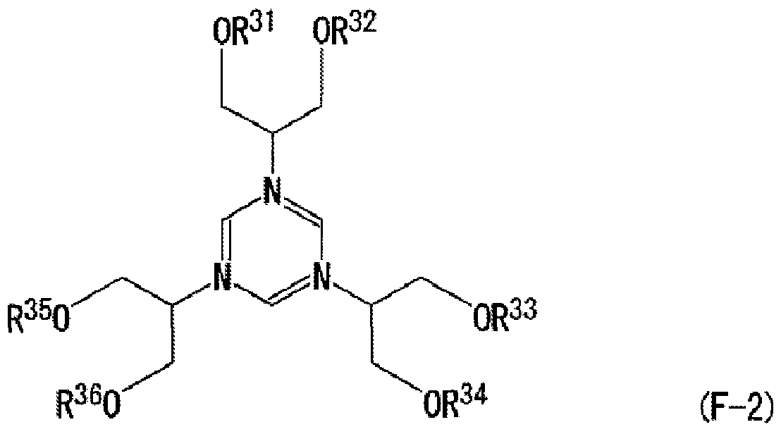
R410、 'OR42
R440 、0 3 (F-3)
(式中、 xは 0〜2の整数; R31〜R36はそれぞれ独立して炭素数 5以下のアルキル基を 示し; R41〜R44はそれぞれ独立して炭素数 5以下のアルキル基を示す。)
[7] 請求項 1に記載のレジストパターン形成方法において、前記超臨界流体は、大気 雰囲気では気体である物質を超臨界状態としたものであるレジストパターン形成方法
[8] 請求項 1に記載のレジストパターン形成方法にぉ 、て、
レジストパターンを、前記超臨界処理液に接触させた後、さらにこのレジストパター ンを(1)加熱、あるいは(2)光を照射し、かつ加熱するレジストパターン形成方法。
[9] 請求項 1に記載のレジストパターン形成方法にぉ 、て、
現像処理をしてレジストパターンを形成する工程と、
現像処理の後、前記レジストパターンを前記超臨界処理液に接触させる工程と、 前記超臨界処理液中の超臨界流体を気化させる工程と、
を有するレジストパターン形成方法。
[10] 請求項 1に記載のレジストパターン形成方法にぉ 、て、
現像処理をしてレジストパターンを形成する工程と、
現像処理の後、前記レジストパターンを、前記超臨界処理液の超臨界前駆体処理 液に接触させる工程と、
前記超臨界前駆体処理液を超臨界状態とし、超臨界処理液とする工程と、 前記超臨界処理液中の超臨界流体を気化させる工程と、
を有するレジストパターン形成方法。
Priority Applications (1)
| Application Number | Priority Date | Filing Date | Title |
|---|---|---|---|
| US11/795,988 US7977036B2 (en) | 2005-01-27 | 2006-01-27 | Resist pattern forming method |
Applications Claiming Priority (2)
| Application Number | Priority Date | Filing Date | Title |
|---|---|---|---|
| JP2005020375A JP4630077B2 (ja) | 2005-01-27 | 2005-01-27 | レジストパターン形成方法 |
| JP2005-020375 | 2005-01-27 |
Publications (1)
| Publication Number | Publication Date |
|---|---|
| WO2006080428A1 true WO2006080428A1 (ja) | 2006-08-03 |
Family
ID=36740452
Family Applications (1)
| Application Number | Title | Priority Date | Filing Date |
|---|---|---|---|
| PCT/JP2006/301297 WO2006080428A1 (ja) | 2005-01-27 | 2006-01-27 | レジストパターン形成方法 |
Country Status (4)
| Country | Link |
|---|---|
| US (1) | US7977036B2 (ja) |
| JP (1) | JP4630077B2 (ja) |
| TW (1) | TWI302642B (ja) |
| WO (1) | WO2006080428A1 (ja) |
Families Citing this family (2)
| Publication number | Priority date | Publication date | Assignee | Title |
|---|---|---|---|---|
| EP2159641A1 (en) * | 2007-06-15 | 2010-03-03 | Fujifilm Corporation | Surface treatment agent for forming pattern and pattern forming method using the treatment agent |
| JP5448536B2 (ja) | 2009-04-08 | 2014-03-19 | 東京エレクトロン株式会社 | レジスト塗布現像装置およびレジスト塗布現像方法、並びにレジスト膜処理装置およびレジスト膜処理方法 |
Citations (6)
| Publication number | Priority date | Publication date | Assignee | Title |
|---|---|---|---|---|
| JP2000089477A (ja) * | 1998-09-11 | 2000-03-31 | Nec Corp | レジストパターンの形成方法 |
| JP2000112150A (ja) * | 1998-10-06 | 2000-04-21 | Nec Corp | パターン形成されたレジスト膜の処理方法 |
| JP2003140359A (ja) * | 2001-10-31 | 2003-05-14 | Matsushita Electric Ind Co Ltd | パターン形成方法 |
| JP2004233953A (ja) * | 2002-12-02 | 2004-08-19 | Tokyo Ohka Kogyo Co Ltd | ポジ型レジスト組成物 |
| JP2004233954A (ja) * | 2002-12-02 | 2004-08-19 | Tokyo Ohka Kogyo Co Ltd | レジストパターン形成方法およびレジストパターン |
| JP2005223118A (ja) * | 2004-02-05 | 2005-08-18 | Nippon Telegr & Teleph Corp <Ntt> | 超臨界処理方法 |
Family Cites Families (14)
| Publication number | Priority date | Publication date | Assignee | Title |
|---|---|---|---|---|
| JP3206989B2 (ja) | 1992-11-13 | 2001-09-10 | 富士写真フイルム株式会社 | ポジ型感光性材料 |
| JPH06230574A (ja) | 1993-02-05 | 1994-08-19 | Fuji Photo Film Co Ltd | ポジ型感光性組成物 |
| KR100234143B1 (ko) | 1996-06-07 | 1999-12-15 | 미야즈 쥰이치로 | 레지스트 물질 및 그 제조 방법 |
| JP3515326B2 (ja) | 1996-06-07 | 2004-04-05 | 日本電信電話株式会社 | レジスト組成物 |
| JP2002341538A (ja) | 2001-05-11 | 2002-11-27 | Fuji Photo Film Co Ltd | 電子線またはx線用ポジ型レジスト組成物 |
| JP2003224050A (ja) | 2002-01-29 | 2003-08-08 | Matsushita Electric Ind Co Ltd | パターン形成方法 |
| US7169540B2 (en) | 2002-04-12 | 2007-01-30 | Tokyo Electron Limited | Method of treatment of porous dielectric films to reduce damage during cleaning |
| CN100335969C (zh) | 2002-04-12 | 2007-09-05 | 东京毅力科创株式会社 | 减少多孔介电薄膜清洗期间损伤的处理方法 |
| JP2003338452A (ja) | 2002-05-22 | 2003-11-28 | Matsushita Electric Ind Co Ltd | パターン形成方法 |
| US6989358B2 (en) | 2002-10-31 | 2006-01-24 | Advanced Technology Materials, Inc. | Supercritical carbon dioxide/chemical formulation for removal of photoresists |
| JP2005202176A (ja) | 2004-01-16 | 2005-07-28 | Hitachi Ltd | パタン形成方法 |
| US20050186515A1 (en) * | 2004-01-23 | 2005-08-25 | Watkins James J. | Structured materials and methods |
| US20060003271A1 (en) | 2004-06-30 | 2006-01-05 | Clark Shan C | Basic supercritical solutions for quenching and developing photoresists |
| KR100654802B1 (ko) | 2004-12-03 | 2006-12-08 | 삼성전자주식회사 | 잉크젯 프린트헤드 및 그 제조방법 |
-
2005
- 2005-01-27 JP JP2005020375A patent/JP4630077B2/ja not_active Expired - Fee Related
-
2006
- 2006-01-27 TW TW095103478A patent/TWI302642B/zh not_active IP Right Cessation
- 2006-01-27 WO PCT/JP2006/301297 patent/WO2006080428A1/ja not_active Application Discontinuation
- 2006-01-27 US US11/795,988 patent/US7977036B2/en not_active Expired - Fee Related
Patent Citations (6)
| Publication number | Priority date | Publication date | Assignee | Title |
|---|---|---|---|---|
| JP2000089477A (ja) * | 1998-09-11 | 2000-03-31 | Nec Corp | レジストパターンの形成方法 |
| JP2000112150A (ja) * | 1998-10-06 | 2000-04-21 | Nec Corp | パターン形成されたレジスト膜の処理方法 |
| JP2003140359A (ja) * | 2001-10-31 | 2003-05-14 | Matsushita Electric Ind Co Ltd | パターン形成方法 |
| JP2004233953A (ja) * | 2002-12-02 | 2004-08-19 | Tokyo Ohka Kogyo Co Ltd | ポジ型レジスト組成物 |
| JP2004233954A (ja) * | 2002-12-02 | 2004-08-19 | Tokyo Ohka Kogyo Co Ltd | レジストパターン形成方法およびレジストパターン |
| JP2005223118A (ja) * | 2004-02-05 | 2005-08-18 | Nippon Telegr & Teleph Corp <Ntt> | 超臨界処理方法 |
Also Published As
| Publication number | Publication date |
|---|---|
| TW200700906A (en) | 2007-01-01 |
| TWI302642B (en) | 2008-11-01 |
| JP2006208721A (ja) | 2006-08-10 |
| US7977036B2 (en) | 2011-07-12 |
| JP4630077B2 (ja) | 2011-02-09 |
| US20080118871A1 (en) | 2008-05-22 |
Similar Documents
| Publication | Publication Date | Title |
|---|---|---|
| TWI451198B (zh) | 正型光阻材料及圖案形成方法 | |
| TWI454847B (zh) | 正型光阻材料及圖案形成方法 | |
| TWI465850B (zh) | 正型阻劑材料及使用其之圖型形成方法 | |
| TWI373691B (en) | Resist pattern forming method | |
| JP2011517079A (ja) | 二重パターン化を用いたフォトレジスト像形成方法 | |
| JP5735458B2 (ja) | ポジ型レジスト材料及びパターン形成方法 | |
| JP4987411B2 (ja) | パターン形成方法 | |
| WO2006027997A1 (ja) | 電子線またはeuv(極端紫外光)用レジスト組成物及びレジストパターン形成方法 | |
| WO2006064626A1 (ja) | 高分子化合物、ポジ型レジスト組成物、およびレジストパターン形成方法 | |
| WO2006123496A1 (ja) | ポジ型レジスト組成物およびレジストパターン形成方法 | |
| WO2007055079A1 (ja) | 感光性樹脂組成物及びパターン形成方法 | |
| US20060166130A1 (en) | Photoresist composition and method for forming resist pattern using the same | |
| WO2005081061A1 (ja) | フォトレジスト組成物およびレジストパターン形成方法 | |
| TWI326014B (en) | A method for forming a resist pattern and a supercritical processing solvent for lithography process | |
| WO2006038477A1 (ja) | 高分子化合物、ポジ型レジスト組成物およびレジストパターン形成方法 | |
| WO2006080428A1 (ja) | レジストパターン形成方法 | |
| JP2004233953A (ja) | ポジ型レジスト組成物 | |
| WO2006112446A1 (ja) | 化合物、溶解抑制剤、ポジ型レジスト組成物、レジストパターン形成方法 | |
| WO2006061975A1 (ja) | レジストパターンの形成方法 | |
| WO2004051380A1 (ja) | レジストパターン形成方法およびレジストパターン | |
| JP4184212B2 (ja) | 低加速電子線用ポジ型レジスト組成物 | |
| JP4159963B2 (ja) | レジスト積層体およびパターン形成方法 | |
| WO2008001544A1 (fr) | Composition de résist positif et procédé de formation d'un motif de résist | |
| WO2006008934A1 (ja) | レジスト組成物およびレジストパターン形成方法 | |
| JP2004354954A (ja) | ホトレジスト組成物及びそれを用いたレジストパターン形成方法 |
Legal Events
| Date | Code | Title | Description |
|---|---|---|---|
| 121 | Ep: the epo has been informed by wipo that ep was designated in this application | ||
| WWE | Wipo information: entry into national phase |
Ref document number: 11795988 Country of ref document: US |
|
| 122 | Ep: pct application non-entry in european phase |
Ref document number: 06712463 Country of ref document: EP Kind code of ref document: A1 |
|
| WWW | Wipo information: withdrawn in national office |
Ref document number: 6712463 Country of ref document: EP |