WO2004103706A2 - Dornverriegelungseinheit für druckwalzendorne in einer rotationsdruckmaschine - Google Patents
Dornverriegelungseinheit für druckwalzendorne in einer rotationsdruckmaschine Download PDFInfo
- Publication number
- WO2004103706A2 WO2004103706A2 PCT/EP2004/005488 EP2004005488W WO2004103706A2 WO 2004103706 A2 WO2004103706 A2 WO 2004103706A2 EP 2004005488 W EP2004005488 W EP 2004005488W WO 2004103706 A2 WO2004103706 A2 WO 2004103706A2
- Authority
- WO
- WIPO (PCT)
- Prior art keywords
- mandrel
- locking unit
- piston
- receiving element
- pressure
- Prior art date
Links
Classifications
-
- B—PERFORMING OPERATIONS; TRANSPORTING
- B41—PRINTING; LINING MACHINES; TYPEWRITERS; STAMPS
- B41F—PRINTING MACHINES OR PRESSES
- B41F13/00—Common details of rotary presses or machines
- B41F13/08—Cylinders
- B41F13/24—Cylinder-tripping devices; Cylinder-impression adjustments
- B41F13/26—Arrangement of cylinder bearings
-
- B—PERFORMING OPERATIONS; TRANSPORTING
- B41—PRINTING; LINING MACHINES; TYPEWRITERS; STAMPS
- B41F—PRINTING MACHINES OR PRESSES
- B41F13/00—Common details of rotary presses or machines
- B41F13/08—Cylinders
- B41F13/20—Supports for bearings or supports for forme, offset, or impression cylinders
-
- B—PERFORMING OPERATIONS; TRANSPORTING
- B41—PRINTING; LINING MACHINES; TYPEWRITERS; STAMPS
- B41P—INDEXING SCHEME RELATING TO PRINTING, LINING MACHINES, TYPEWRITERS, AND TO STAMPS
- B41P2227/00—Mounting or handling printing plates; Forming printing surfaces in situ
- B41P2227/20—Means enabling or facilitating exchange of tubular printing or impression members, e.g. printing sleeves, blankets
- B41P2227/21—Means facilitating exchange of sleeves mounted on cylinders without removing the cylinder from the press
Definitions
- Mandrel locking unit for printing roller mandrels in a rotary printing machine
- the invention relates to a pin locking unit according to the preamble of claim 1.
- the prior art therefore includes pressure rollers, which comprise pressure roller mandrels, from which pressure roller sleeves - the so-called seals - can be pulled off and pushed back on.
- the printing roller mandrels are usually mounted on one end in a floating manner. The free end is enclosed in the printing operation by a bearing that can be removed for the purpose of changing sleeves.
- all the rollers involved in a printing process are to be understood as printing rollers.
- Patent specification DE 197 05 369 A1 shows such a printing press, for example.
- Each roller involved in the printing process is assigned a bearing block which, after the bearing connection has been released, can be moved relative to the roller.
- the actual warehouse is located in a bearing head. This can be moved in guides parallel to the axis of the roller.
- the process is carried out by a piston-cylinder unit.
- the unit, consisting of the bearing, the mandrel receiving element, the guides and the piston-cylinder unit, is often also referred to as a mandrel locking unit.
- a disadvantage of this construction is that the mandrel locking unit has a constructional depth which is composed at least of the depth of the bearing piston and the maximum stroke of the piston-cylinder unit. This overall depth causes space consumption on the operating side of the printing press, which has a restrictive effect on the ease of use of the printing press.
- US Pat. No. 3,147,702 has a similar mandrel locking unit, in which, however, it is not the bearing that is pulled off the roller, but the roller pin that is pulled off the roller.
- the shaft journal is therefore part of the mandrel locking unit.
- the shaft journal is surrounded by the piston designed as a cavity.
- the very large structural depth is also disadvantageous in this Dornver ⁇ egelungstechnik.
- the object of the invention is therefore to propose a mandrel locking unit which has a more compact design with a smaller overall depth.
- the interface - as stated in the preamble of the main claim - is the part of the surface of the piston which delimits the pressure space of the pressure medium cylinder.
- the mandrel receiving element is a component suitable for receiving the dome on the mandrel support surface. Since the mandrel is held on its bearing surface with the help of bearings, this component usually also encloses this or these bearings. As a rule, the dome receiving element is designed as a sleeve. In order to move the mandrel receiving element, it is connected to the piston at a connection point.
- the distance between the interface and the connection point is less than three quarters of the maximum stroke of the piston in the cylinder. In a particularly preferred embodiment, the distance between the interface and the connection point is less than half the maximum stroke of the piston in the cylinder.
- Such an embodiment offers a good compromise between a compact design and reliable guiding of the mandrel receiving element in the guide sleeve, for example in order to prevent tilting. Of course, the distance can be significantly smaller.
- the construction enables the travel range of the mandrel receiving element and the pressure space in which the piston can move to merge with one another in the axial direction.
- the piston rod which in known mandrel locking units is at least as long as the maximum stroke of the piston, can even be dispensed with entirely.
- the inner diameter of the pressure medium cylinder is larger than the outer diameter of the mandrel receiving element.
- the piston is a disc without a piston rod. Since the mandrel receiving element then takes over the guiding function of the piston rod, this must have a greater overall length than the maximum stroke of the piston.
- both the mandrel receiving element and the pressure medium cylinder are circular cylindrical designed.
- the axes of symmetry of these two circular-cylindrical components run parallel to one another, but are not in alignment. There is therefore a slight acentric connection between these two components, which offers the advantage that the mandrel receiving element can be arranged on one side of the guide bush. If two printing rollers with a small outside diameter work together in a printing press, the minimum outside diameter is given by the dimensions of the mandrel locking unit. If the mandrel receiving element is arranged offset, the minimum distance can be reduced again, so that it is possible to reduce the minimum printing length of the printing press.
- the present invention is advantageously used in flexographic or gravure printing presses, but can also be used in printing presses which operate according to other principles.
- FIG. 1 shows a mandrel locking unit according to the invention with an enclosed mandrel support surface
- Fig. 2 shows a mandrel locking unit according to the invention with released
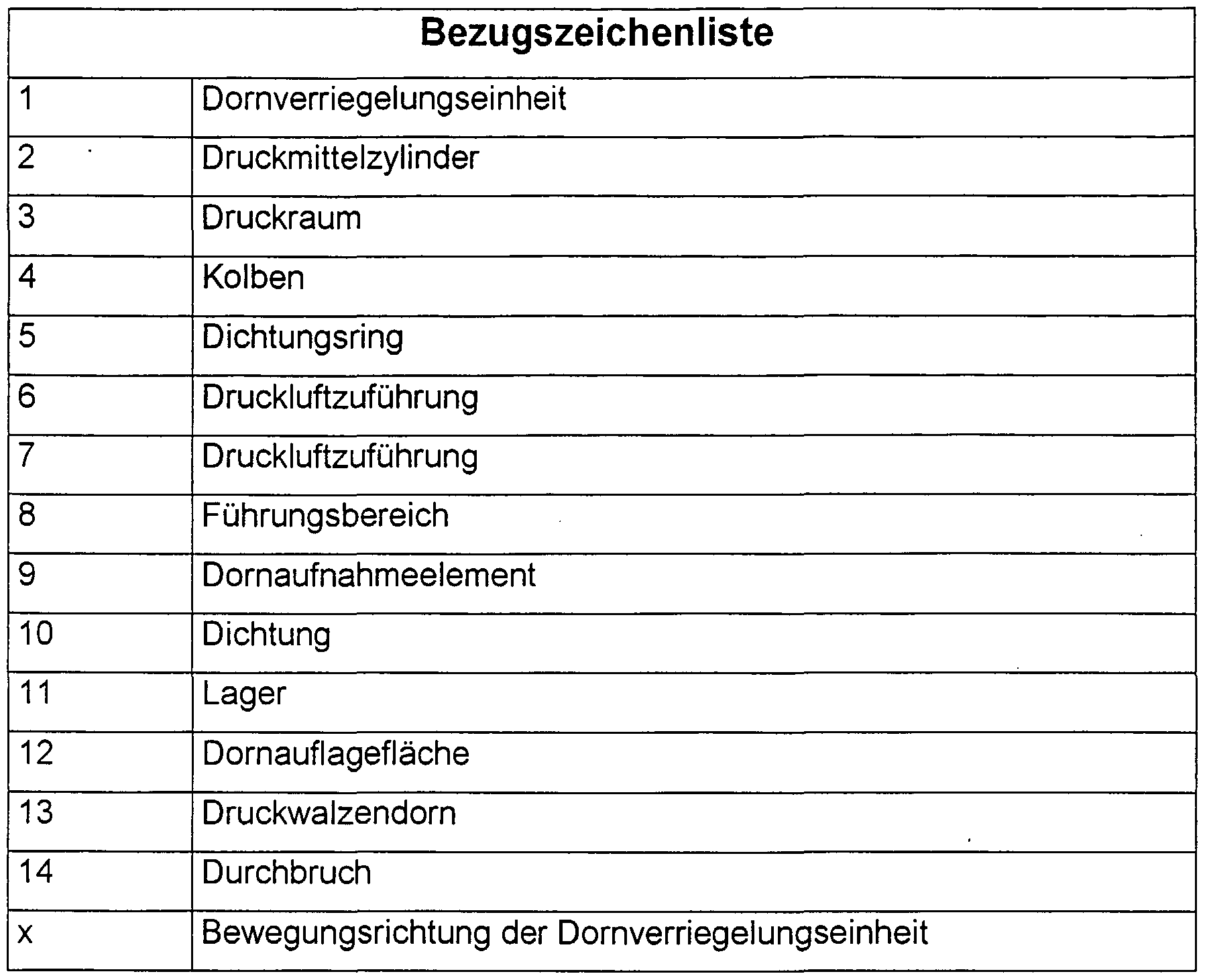
- Figures 1 and 2 show a mandrel locking unit 1, which consists essentially of a pressure medium cylinder 2.
- the pressure medium cylinder 2 has a pressure chamber 3, in which a piston 4 is displaceable.
- the piston 4 has a sealing ring 5 on its outer circumference, which is known to prevent compressed air from passing from one side to the other side of the piston 4.
- the compressed air is introduced into the pressure chamber 3 through the compressed air supply lines 6, 7.
- the pressure medium cylinder 2 has, apart from the pressure chamber 3, a guide area 8 in which the mandrel receiving element 9 is slidably mounted.
- the pressure chamber 3 and the guide area 8 are separated from one another by the mandrel receiving element 9 and the seal 10.
- the mandrel receiving element 9 carries a bearing 11, for example a roller bearing, which is able to enclose the mandrel support surface 12 of the pressure roller dome 13.
- a bearing 11 for example a roller bearing
- the two components are connected to one another in a manner not shown. This connection is advantageously made with a screw.
- the pressure chamber is pressurized with compressed air via the compressed air supply 6, so that the piston 4 moves in the axial direction towards the pressure roller dome 13. Axial guidance of the piston 4 is ensured by the guidance of the mandrel receiving element 9 in the pressure medium cylinder 2.
- the pressure chamber 3 remains pressurized with compressed air, so that no unwanted separation of the bearing 11 and the mandrel support surface 12 occurs.
- the pressure chamber is pressurized with compressed air via the compressed air supply 7, so that the piston 4 and with it the mandrel receiving element 9 move away from the pressure roller dome 13 into its end position shown in FIG. 2 emotional.
- the pressure roller dome 13 and the mandrel locking unit 1 can be moved relative to one another.
- the mandrel locking unit 1 is moved in the direction of the arrow x.
- the pressure medium cylinder 2 has an opening 14 at at least one point.
- FIG 3 shows the slightly offset arrangement of the piston 4 and the mandrel receiving element 9 in order to minimize the distance between the mandrel receiving element 9 and the outer edge of the pressure medium cylinder 2 on the opening 14 side.
Abstract
Description
Claims
Priority Applications (4)
| Application Number | Priority Date | Filing Date | Title |
|---|---|---|---|
| AT04733566T ATE464183T1 (de) | 2003-05-23 | 2004-05-18 | Dornverriegelungseinheit für druckwalzendorne in einer rotationsdruckmaschine |
| EP04733566A EP1628828B1 (de) | 2003-05-23 | 2004-05-18 | Dornverriegelungseinheit für druckwalzendorne in einer rotationsdruckmaschine |
| US10/557,826 US7900559B2 (en) | 2003-05-23 | 2004-05-18 | Mandrel locking unit for printing roller mandrels in a rotary printing machine |
| DE502004011043T DE502004011043D1 (de) | 2003-05-23 | 2004-05-18 | Dornverriegelungseinheit für druckwalzendorne in einer rotationsdruckmaschine |
Applications Claiming Priority (2)
| Application Number | Priority Date | Filing Date | Title |
|---|---|---|---|
| DE10323805.0 | 2003-05-23 | ||
| DE10323805A DE10323805B3 (de) | 2003-05-23 | 2003-05-23 | Dornverriegelungseinheit für Druckwalzendorne in einer Rotationsdruckmaschine |
Publications (2)
| Publication Number | Publication Date |
|---|---|
| WO2004103706A2 true WO2004103706A2 (de) | 2004-12-02 |
| WO2004103706A3 WO2004103706A3 (de) | 2005-05-26 |
Family
ID=33154510
Family Applications (1)
| Application Number | Title | Priority Date | Filing Date |
|---|---|---|---|
| PCT/EP2004/005488 WO2004103706A2 (de) | 2003-05-23 | 2004-05-18 | Dornverriegelungseinheit für druckwalzendorne in einer rotationsdruckmaschine |
Country Status (6)
| Country | Link |
|---|---|
| US (1) | US7900559B2 (de) |
| EP (1) | EP1628828B1 (de) |
| AT (1) | ATE464183T1 (de) |
| DE (2) | DE10323805B3 (de) |
| ES (1) | ES2343250T3 (de) |
| WO (1) | WO2004103706A2 (de) |
Cited By (2)
| Publication number | Priority date | Publication date | Assignee | Title |
|---|---|---|---|---|
| US7699001B2 (en) * | 2005-04-13 | 2010-04-20 | Man Roland Druckmaschinen Ag | Apparatus for pressing a covering onto a printing-unit cylinder for a rotary press |
| US7762185B2 (en) * | 2004-09-29 | 2010-07-27 | Goss International Corporation | Inboard cantilever cylinder support for printing presses |
Families Citing this family (3)
| Publication number | Priority date | Publication date | Assignee | Title |
|---|---|---|---|---|
| US9126395B2 (en) | 2012-04-30 | 2015-09-08 | Rossini S.P.A. | Bridge sleeves with diametrically expandable stabilizers |
| US9120302B2 (en) | 2012-04-30 | 2015-09-01 | Rossini S.P.A. | Bridge sleeves with diametrically expandable stabilizers |
| ES2941384T3 (es) * | 2020-05-26 | 2023-05-22 | Bobst Bielefeld Gmbh | Conjunto de cojinete para soportar un cilindro de impresión o un rodillo anilox en una máquina de impresión y máquina de impresión |
Citations (4)
| Publication number | Priority date | Publication date | Assignee | Title |
|---|---|---|---|---|
| DE543117C (de) * | 1930-03-02 | 1932-02-01 | Albert Schnellpressen | Lagerung fuer Zylinder an Druckmaschinen, insbesondere fuer die Formzylinder an Rotationstiefdruckmaschinen |
| US2460504A (en) * | 1944-10-24 | 1949-02-01 | William C Huebner | Printing apparatus |
| US3147702A (en) * | 1962-10-01 | 1964-09-08 | Clary Corp | Printing press roll supporting and adjusting means |
| DE19705369A1 (de) * | 1997-02-12 | 1998-09-17 | Windmoeller & Hoelscher | Druckmaschine |
Family Cites Families (5)
| Publication number | Priority date | Publication date | Assignee | Title |
|---|---|---|---|---|
| US4083205A (en) * | 1970-11-05 | 1978-04-11 | Imperial Chemical Industries Limited | Textile printing apparatus |
| JP2874128B2 (ja) * | 1993-12-27 | 1999-03-24 | 株式会社神戸製鋼所 | タイヤ試験機のリムクランプ装置 |
| IT1277167B1 (it) * | 1995-03-20 | 1997-11-05 | Rossini Erminio Spa | Perfezionamenti ai mandrini deformabili per cilindri da stampa rotativa |
| SE516997C2 (sv) * | 1999-11-16 | 2002-04-02 | Etp Transmission Ab | Monteringsverktyg för hydromekanisk chuck |
| US20030145472A1 (en) * | 2002-02-01 | 2003-08-07 | Swift Edgar Leon | Reciprocating saw with flush cutting capability |
-
2003
- 2003-05-23 DE DE10323805A patent/DE10323805B3/de not_active Expired - Fee Related
-
2004
- 2004-05-18 EP EP04733566A patent/EP1628828B1/de not_active Not-in-force
- 2004-05-18 DE DE502004011043T patent/DE502004011043D1/de active Active
- 2004-05-18 AT AT04733566T patent/ATE464183T1/de not_active IP Right Cessation
- 2004-05-18 ES ES04733566T patent/ES2343250T3/es active Active
- 2004-05-18 WO PCT/EP2004/005488 patent/WO2004103706A2/de active Application Filing
- 2004-05-18 US US10/557,826 patent/US7900559B2/en not_active Expired - Fee Related
Patent Citations (4)
| Publication number | Priority date | Publication date | Assignee | Title |
|---|---|---|---|---|
| DE543117C (de) * | 1930-03-02 | 1932-02-01 | Albert Schnellpressen | Lagerung fuer Zylinder an Druckmaschinen, insbesondere fuer die Formzylinder an Rotationstiefdruckmaschinen |
| US2460504A (en) * | 1944-10-24 | 1949-02-01 | William C Huebner | Printing apparatus |
| US3147702A (en) * | 1962-10-01 | 1964-09-08 | Clary Corp | Printing press roll supporting and adjusting means |
| DE19705369A1 (de) * | 1997-02-12 | 1998-09-17 | Windmoeller & Hoelscher | Druckmaschine |
Cited By (2)
| Publication number | Priority date | Publication date | Assignee | Title |
|---|---|---|---|---|
| US7762185B2 (en) * | 2004-09-29 | 2010-07-27 | Goss International Corporation | Inboard cantilever cylinder support for printing presses |
| US7699001B2 (en) * | 2005-04-13 | 2010-04-20 | Man Roland Druckmaschinen Ag | Apparatus for pressing a covering onto a printing-unit cylinder for a rotary press |
Also Published As
| Publication number | Publication date |
|---|---|
| US20060266236A1 (en) | 2006-11-30 |
| DE502004011043D1 (de) | 2010-05-27 |
| ES2343250T3 (es) | 2010-07-27 |
| US7900559B2 (en) | 2011-03-08 |
| EP1628828B1 (de) | 2010-04-14 |
| EP1628828A2 (de) | 2006-03-01 |
| ATE464183T1 (de) | 2010-04-15 |
| WO2004103706A3 (de) | 2005-05-26 |
| DE10323805B3 (de) | 2004-11-11 |
Similar Documents
| Publication | Publication Date | Title |
|---|---|---|
| DE2626954C2 (de) | Steuerschieberanordnung für eine durch Druckluft angetriebene Hydraulikpumpe | |
| EP1157855B1 (de) | Gummizylinderhülse, insbesondere für Offset-Rollenrotationsdruckmaschinen | |
| DE19846677C5 (de) | Druckwalze mit austauschbarem äußeren Mantel | |
| DE1505600A1 (de) | Bremsvorrichtung | |
| DE2331273B2 (de) | Hydrostatische Radialkolbenmaschine | |
| DE10118132B4 (de) | Farbwerk einer Rotationsdruckmaschine | |
| DE2137385A1 (de) | Gesteinsbohrer | |
| EP0683043B1 (de) | Druckwerkszylinder einer Rollenrotationsdruckmaschine | |
| DE10323805B3 (de) | Dornverriegelungseinheit für Druckwalzendorne in einer Rotationsdruckmaschine | |
| DE60200544T2 (de) | Rollenträger für Druckvorrichtung | |
| DE102004051041B3 (de) | Druckplattenzylinder | |
| DE2510384C3 (de) | Zahnärztliches Handstück | |
| DE202010012321U1 (de) | Vorrichtung, insbesondere Stangengreifer, zum Greifen, Halten und Freigeben von zu bearbeitendem Material | |
| DE3730214C2 (de) | ||
| DE453698C (de) | Walzenlager mit hydraulischer Anpressvorrichtung | |
| EP2323850B1 (de) | Farbwerk einer druckmaschine | |
| DE3900281A1 (de) | Tiefdruckzylinder, insbesondere fuer den illustrationsdruck | |
| DE2610831C3 (de) | Anordnung zum Weiterleiten von Schmiermittel Ober einen Bewegungsspalt hinweg | |
| EP1433598B1 (de) | Einrichtung zur Formatverstellung an bogenführenden Trommeln von Bogendruckmaschinen | |
| DE102008018590B4 (de) | Zylinder für eine lösbare Verbindung mit mindestens einem Arbeitsmittel | |
| DE2660470C2 (de) | Druckluftbetriebene Hydraulikpumpe | |
| DE10306196B3 (de) | Farbübertragungswalze | |
| DE1223257B (de) | Pneumatischer Dreistellungs-Arbeitszylinder | |
| DE102010001747A1 (de) | Schmitzring sowie ein Verfahren zum reversiblen Verändern eines Außenradius eines Schmitzrings | |
| DE2605648C2 (de) | Pneumatisch-hydraulische Blindnieteinrichtung |
Legal Events
| Date | Code | Title | Description |
|---|---|---|---|
| AK | Designated states |
Kind code of ref document: A2 Designated state(s): AE AG AL AM AT AU AZ BA BB BG BR BW BY BZ CA CH CN CO CR CU CZ DE DK DM DZ EC EE EG ES FI GB GD GE GH GM HR HU ID IL IN IS JP KE KG KP KR KZ LC LK LR LS LT LU LV MA MD MG MK MN MW MX MZ NA NI NO NZ OM PG PH PL PT RO RU SC SD SE SG SK SL SY TJ TM TN TR TT TZ UA UG US UZ VC VN YU ZA ZM ZW |
|
| AL | Designated countries for regional patents |
Kind code of ref document: A2 Designated state(s): BW GH GM KE LS MW MZ NA SD SL SZ TZ UG ZM ZW AM AZ BY KG KZ MD RU TJ TM AT BE BG CH CY CZ DE DK EE ES FI FR GB GR HU IE IT LU MC NL PL PT RO SE SI SK TR BF BJ CF CG CI CM GA GN GQ GW ML MR NE SN TD TG |
|
| DPEN | Request for preliminary examination filed prior to expiration of 19th month from priority date (pct application filed from 20040101) | ||
| 121 | Ep: the epo has been informed by wipo that ep was designated in this application | ||
| WWE | Wipo information: entry into national phase |
Ref document number: 2004733566 Country of ref document: EP |
|
| WWE | Wipo information: entry into national phase |
Ref document number: 2006266236 Country of ref document: US Ref document number: 10557826 Country of ref document: US |
|
| WWP | Wipo information: published in national office |
Ref document number: 2004733566 Country of ref document: EP |
|
| WWP | Wipo information: published in national office |
Ref document number: 10557826 Country of ref document: US |