US9811187B2 - Information processing apparatus, information processing method, and program - Google Patents
Information processing apparatus, information processing method, and program Download PDFInfo
- Publication number
- US9811187B2 US9811187B2 US12/719,617 US71961710A US9811187B2 US 9811187 B2 US9811187 B2 US 9811187B2 US 71961710 A US71961710 A US 71961710A US 9811187 B2 US9811187 B2 US 9811187B2
- Authority
- US
- United States
- Prior art keywords
- detection area
- state
- operating tool
- display panel
- detected
- Prior art date
- Legal status (The legal status is an assumption and is not a legal conclusion. Google has not performed a legal analysis and makes no representation as to the accuracy of the status listed.)
- Expired - Fee Related, expires
Links
Images


Classifications
-
- G—PHYSICS
- G06—COMPUTING OR CALCULATING; COUNTING
- G06F—ELECTRIC DIGITAL DATA PROCESSING
- G06F3/00—Input arrangements for transferring data to be processed into a form capable of being handled by the computer; Output arrangements for transferring data from processing unit to output unit, e.g. interface arrangements
- G06F3/01—Input arrangements or combined input and output arrangements for interaction between user and computer
- G06F3/03—Arrangements for converting the position or the displacement of a member into a coded form
- G06F3/041—Digitisers, e.g. for touch screens or touch pads, characterised by the transducing means
- G06F3/0412—Digitisers structurally integrated in a display
-
- G—PHYSICS
- G06—COMPUTING OR CALCULATING; COUNTING
- G06F—ELECTRIC DIGITAL DATA PROCESSING
- G06F3/00—Input arrangements for transferring data to be processed into a form capable of being handled by the computer; Output arrangements for transferring data from processing unit to output unit, e.g. interface arrangements
- G06F3/01—Input arrangements or combined input and output arrangements for interaction between user and computer
- G06F3/048—Interaction techniques based on graphical user interfaces [GUI]
- G06F3/0487—Interaction techniques based on graphical user interfaces [GUI] using specific features provided by the input device, e.g. functions controlled by the rotation of a mouse with dual sensing arrangements, or of the nature of the input device, e.g. tap gestures based on pressure sensed by a digitiser
- G06F3/0488—Interaction techniques based on graphical user interfaces [GUI] using specific features provided by the input device, e.g. functions controlled by the rotation of a mouse with dual sensing arrangements, or of the nature of the input device, e.g. tap gestures based on pressure sensed by a digitiser using a touch-screen or digitiser, e.g. input of commands through traced gestures
Definitions
- the present invention relates to an information processing apparatus, an information processing method, and a program.
- a touch panel display panel
- interaction between a user and a device is performed by detecting a contact state of an operating tool such as a finger or a stylus with the touch panel.
- an operating tool such as a finger or a stylus
- a touch panel which enables interaction between a user and a device by detecting proximity by the operating tool.
- the accuracy of detecting the positional information of the operating tool is lower than that for detection of the contact state. Therefore, even though the operating tool is detected inside a detection area set for each object, it is sometimes detected also outside by its slight movement or even though the operating tool is detected outside of the detection area, it is sometimes detected also inside the detection area by its slight movement, which may cause wrong operation. Particularly, when the operating tool detected inside the detection area of an object to be selected is also detected inside the detection area of an object not to be selected, the object not to be selected is changed into a selected state instead of the object to be selected and there may occur wrong operation.
- an information processing apparatus including a display panel for displaying at least one object in a selected state or in unselected state, a detection area setting unit for setting, per object on the display panel, a first detection area covering a display area of the object and a second detection area covering the first detection area and being larger than the first detection area, an operating tool detecting unit for detecting an operating tool being in proximity to the display panel and a state managing unit for changing the object into the selected state when the operating tool is detected within the first detection area of the object in the unselected state, and for changing the object into the unselected state when the operating tool is not detected within the second detection area of the object in the selected state.
- the information processing apparatus does not recognize an object in the unselected state as that in the selected state until the operating tool is detected inside the first detection area nor an object in the selected state as that in the unselected state while the operating tool is detected inside the second detection area even though the operating tool is not detected inside the first detection area.
- This prevents an object not to be selected from being changed into the selected state by mistake and an object to be selected from being changed into the unselected state by mistake.
- the operability of the touch panel can be enhanced.
- the detection area setting unit may set, per object on the display panel, the first detection area covering the display area of the object in a horizontal direction relative to the display panel and the second detection area covering the first detection area and extending to outside the first detection area in the horizontal direction relative to the display panel.
- the state managing unit may change the object into the selected state when the operating tool is detected within the first detection area of the object in the unselected state and in proximity to the display panel within a predetermined vertical distance, and may change the object into the unselected state when the operating tool is not detected within the second detection area of the object in the selected state and in proximity to the display panel within a predetermined vertical distance.
- the detection area setting unit may set, per object on the display panel, the first detection area covering the display area of the object in a horizontal direction and in a vertical direction relative to the display panel and the second detection area covering the first detection area, extending to outside the first detection area in the horizontal direction relative to the display panel and extending more away from the display panel than the first detection area in the vertical direction relative to the display panel.
- the state managing unit may change the object into the selected state when the operating tool is detected within the first detection area of the object in the unselected state, and may change the object into the unselected state when the operating tool is not detected within the second detection area of the object in the selected state.
- the operating tool detecting unit may detect a movement history of the operating tool moving in proximity to the display panel.
- the detection area setting unit may set, per object on the display panel, the first detection area and/or the second detection area in accordance with the movement history of the operating tool.
- the detection area setting unit may extend the second detection area of the object to an outside of the second detection area in a first direction when the operating tool, moving from an outside of the first detection area of the object to an inside thereof, from the first direction to a second direction, is detected inside of the first detection area.
- the detection area setting unit may reduce the first detection area of the object to an inside of the first detection area in the first direction when the operating tool, moving from the inside of the first detection area of the object to the outside thereof, from the first direction to the second direction, is detected outside the first detection area.
- the state managing unit may maintain a selected state of a first object, when the operating tool is detected within an area where the second detection area of the first object in the selected state overlaps the first detection area of second object in an unselected state.
- an information processing method including the steps of displaying at least one object in a selected state or in unselected state on a display panel, setting, per object on the display panel, a first detection area covering a display area of the object and a second detection area covering the first detection area and being larger than the first detection area, detecting an operating tool being in proximity to the display panel and changing the object into the selected state when the operating tool is detected within the first detection area of the object in the unselected state, and changing the object into the unselected state when the operating tool is not detected within the second detection area of the object in the selected state.
- the object in the unselected state is prevented from being changed into the selected state before the operating tool is detected inside the first detection area and the object in the selected state is prevented from being changed into the unselected state as long as the operating tool is detected in the second detection area even if the operating tool is not selected in the first detection area.
- This prevents the object not to be selected from being changed into the selected state by mistake and the object to be selected from being changed into the unselected state by mistake.
- the operability of the touch panel can be enhanced.
- a program for causing a computer to execute the information processing method according to the second embodiment of the present invention is provided.
- the information processing apparatus the information processing method and the program which are capable of enhancing the operability of a touch panel for detecting the proximity of an operating tool.
- FIG. 1 illustrates an overview of an information processing apparatus according to an embodiment of the invention
- FIG. 2 is a block diagram illustrating an example of functional configuration of the information processing apparatus according to the embodiment of the invention
- FIG. 3 illustrates an example of an object displayed on a touch panel
- FIG. 4 illustrates a method for detecting the position of an operating tool
- FIG. 5 is a schematic view illustrating a first detection area and a second detection area set for each object
- FIG. 6 is a schematic view illustrating transition of the object state in accordance with the position of the operating tool in the X-Y direction with respect to the touch panel;
- FIG. 7 is a schematic view illustrating transition of the object state in accordance with the position of the operating tool moving in the X-Y direction with respect to the touch panel;
- FIG. 8 is a schematic view illustrating transition of the states of adjacent objects in accordance with the position of the operating tool moving in the X-Y direction with respect to the touch panel;
- FIG. 9 is a schematic view illustrating a method for changing settings of the detection areas in accordance with a movement history of the operating tool moving in the X-Y direction with respect to the touch panel;
- FIG. 10 is a schematic view illustrating transition of the object state in accordance with the position of the operating tool moving in the Z direction with respect to the touch panel;
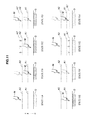
- FIG. 11 is a schematic view illustrating a method for changing settings of the detection area in accordance with the movement history of the operating tool moving in the Z direction with respect to the touch panel;
- FIG. 12A illustrates transition of the object state in accordance with the position of the operating tool moving in the X-Y, Z directions with respect to the touch panel;
- FIG. 12B illustrates transition of the object state in accordance with the position of the operating tool moving in the X-Y, Z directions with respect to the touch panel
- FIG. 13 is a block diagram illustrating an example of hardware configuration of the information processing apparatus.
- FIG. 1 illustrates an overview of an information processing apparatus 100 according to an embodiment of the present invention.
- the information processing apparatus 100 according to an embodiment of the present invention has a touch panel (display panel) 110 capable of detecting proximity of an operating tool M such as a finger, a stylus or the like.
- a touch panel display panel
- an operating tool M such as a finger, a stylus or the like.
- the information processing apparatus 100 is equipped with a built-in touch panel 110 .
- the information processing apparatus 100 may be provided with a touch panel 110 which is attached externally thereto via communication means.
- the information processing apparatus 100 displays one or more objects O such as icons or the like on the touch panel 110 and sets a detection area A including a display area of the object O on the touch panel 110 for each of the objects O.
- the information processing apparatus 100 detects the operating tool M in proximity to the touch panel 110 and brings the object O into the selected state or the unselected state in accordance with detection of the operating tool M inside the detection area A of the object O (In the following, the dark and light hatching indicates the object in the selected and unselected state respectively).
- the objects O include, for example, any objects that constitute graphical user interface such as icons, buttons, thumbnails and the like.
- the information processing apparatus 100 sets, together with a detection area A 1 covering the display area of the object O, a detection area A 2 that covers the detection area A 1 and is larger than the detection area A 1 on the touch panel 110 for each of the objects O. Then, the information processing apparatus 100 , as illustrated in left side view of FIG. 1 , brings the object O into the selected state when the operating tool M is detected inside the detection area A 1 of the object O in the unselected state (light hatching). Besides, as illustrated in the right side view of FIG. 1 , the information processing apparatus 100 brings the object O into the unselected state when the operating tool M is not detected inside the detection area A 2 of the object O in the selected state (dark hatching).
- the object O in the unselected state is prevented from being changed into the selected state before the operating tool M is detected inside the detection area A 1 of the object O, and the object O in the selected state is prevented from being changed into the unselected state as long as the operating tool M is detected inside the detection area A 2 even when the operating tool M is not detected inside the detection area A 1 of the object O.
- it can prevent the object O not to be selected from being changed into the selected state by mistake and the object O to be selected from being changed into the unselected state by mistake.
- the operability of the touch panel 110 can be enhanced.
- FIG. 2 is a view illustrating an example of functional configuration of the information processing apparatus 100 according to the embodiment of the present invention.
- the information processing apparatus 100 has a touch panel (display panel) 110 , a detection area setting unit 120 , an operating tool detecting unit 130 , a state managing unit 140 , a display control unit 150 , a storage unit 160 and an execution processing unit 170 .
- the touch panel 110 displays an information processing result by the information processing apparatus 100 based on display data supplied from the display control unit 150 and particularly, displays objects O such as icons based on object data and position data.
- the touch panel 110 detects the operating tool M which is in proximity to or in contact with the touch panel 110 .
- the touch panel 110 includes an optical sensor 112 and a read circuit 114 .
- the optical sensor 112 detects the intensity of external light incoming to the touch panel 110
- the read circuit 114 reads the intensity of the external light detected by the optical sensor 112 and detects the shadow of the operating tool M.
- the shadow of the operating tool M is shadow data expressing the position on the touch panel 110 and the shape of the operating tool M.
- the shadow of the operating tool M is projected on the touch panel 110 , the projected shadow is read by the read circuit 114 and supplied to the operating tool detecting unit 130 as shadow data.
- the detection area setting unit 120 sets a detection area A 1 and a detection area A 2 on the touch panel 110 for each object O.
- the detection area A 1 is an area covering a display area of the object O
- the detection area A 2 is an area which covers the detection area A 1 and is larger than the detection area A 1 .
- the detection area setting unit 120 uses the position data of the object O stored in the storage unit 160 and a predetermined setting value as a basis to set the detection areas A 1 and A 2 covering the display area of the object O on the touch panel 110 .
- the setting value is used for setting coverage of the detection areas A 1 and A 2 in accordance with the display area of the object O.
- the detection area A 1 is an area extending in the horizontal direction (X-Y direction) relative to the touch panel 110 so as to cover the display area of the object O, which area is set as an area (space) extended in the vertically upward direction (Z direction) relative to the touch panel 110 (which will be described in detail later).
- the detection area A 2 is set as an area (space) covering the detection area A 1 (space) and further extended in the X-Y and/or Z direction.
- the operating tool detecting unit 130 detects the operating tool M based on the shadow data supplied from the read circuit 114 and detects the position of the operating tool M in proximity to the touch panel 110 .
- the shadow of the operating tool M is detected by the read circuit 114 in accordance with the proximity of the operating tool M, and supplied to the operating tool detecting unit 130 as shadow data expressing the position on the touch panel 110 and the shape of the operating tool M.
- the operating tool detecting unit 130 for example, analyzes the shadow data and detects the specific position of the operating tool M including the tip end of the stylus, finger or the like.
- the specific position of the operating tool M is supplied to the state managing unit 140 as operating tool position data.
- setting of the detection area A 1 and/or the detection area A 2 can be changed in accordance with the movement history of the operating tool M moving over the touch panel 110 in proximity thereto.
- the operating tool detecting unit 130 stores the movement history of the operating tool M moving over the touch panel 110
- the detection area setting unit 120 changes the setting of the detection area A 1 and/or the detection area A 2 based on the movement history of the operating tool M.
- the state managing unit 140 changes state data expressing the selected state or unselected state of the object O in accordance with the detection status of the operating tool M in proximity to the touch panel 110 .
- the state managing unit 140 reads area setting data of the detection areas A 1 and A 2 of each object O from the detection area setting unit 120 and receives the operating tool position data from the operating tool detecting unit 130 .
- the state managing unit 140 uses the state data of the object O stored in advance, the operating tool position data and the area setting data as a basis to specify the object O of which the state data is to be changed, changes the state data of the object O and supplies it to the execution processing unit 170 with an object ID.
- the state managing unit 140 When the operating tool M is detected within the detection area A 1 of the object O in the unselected state, the state managing unit 140 changes the state data of the object O to the selected state. Besides, when the operating tool M is not detected within the detection area A 2 of the object O in the selected state, the state managing unit 140 changes the state data of the object O to the unselected state.
- the display control unit 150 controls display of the information processing result by the touch panel 110 and particularly the display of the object O.
- the display control unit 150 supplies the display data and the like to the touch panel 110 based on the processing result supplied from the execution processing unit 170 .
- the display control unit 150 supplies the touch panel 110 with the position data and the object data stored in the storage unit 160 .
- the storage unit 160 stores object data, position data, entity data for the object O and an execution application for the entity data, in association with the object ID of the object O.
- the object data is, for example, image data of the object O.
- the position data is data designating the display position and display area on the touch panel 110 and is updated in accordance with the movement operation when the object O is moved.
- the entity data is data for predetermined processing executed when the object O displayed on the touch panel 110 is selected, including image data of the object O and the like.
- the execution application is a program for executing the predetermined processing of the entity data, including a display program of the image data and the like.
- the execution processing unit 170 executes the predetermined processing of the object O based on the object ID and the state data supplied from the state managing unit 140 . For example, when the state data of the object O is changed from the unselected state to the selected state, the execution processing unit 170 uses the object ID as a basis to read the entity data and the execution application of the object O from the storage unit 160 and executes the predetermined processing.
- the execution processing unit 170 for example, processes the image data as entity data with use of the image display application and supplies the processing result to the display control unit 150 .
- each of the structural components of the information processing apparatus 100 may be configured of a general-purpose member or circuit or hardware for special function of the structural component. Besides, at least a part of the functions of each structural component may be implemented by a program executed on the CPU.
- FIG. 3 is a view illustrating an example of objects O displayed on the touch panel 110 .
- displayed on the touch panel 110 are various objects O including a browser starting icon O 1 , a camera mode staring icon O 2 and the like.
- the user moves the operating tool M on the touch panel 110 thereby to operate selection or non-selection of the object O.
- the information processing apparatus 100 starts or ends execution of processing of the object O, such as execution of camera program, browser program or the like.
- FIG. 4 illustrates the method for detecting the operating tool position.
- the information processing apparatus 100 detects the shadow of the operating tool M projected on the touch panel 110 and detects the contact position or proximity position of the operating tool M.
- the pixel coordinate pair of the touch panel 110 is indicated in the horizontal axis and the shadow of the operating tool M detected per pixel is indicated in the vertical axes.
- the shadow of the operating tool M such as finger or stylus is dark at the center part Mm of the operating tool M and is light at the contour part Me.
- the center part Mm of the operating tool M in proximity to the touch panel 110 is detected by detecting the shadow (solid line) exceeding a predetermined threshold Tha. Further, when the operating tool M is in contact with the touch panel 110 , the center part Mm of the operating tool M in contact with the touch panel 110 and the contour part Me of the operating tool M in proximity to the touch panel 110 are detected by detecting the shadow (dotted line) exceeding a threshold Thb which is greater than the threshold Tha.
- the position of the operating tool M in the X-Y direction is detected from the position of the center part Mm of the operating tool M in the X-Y direction relative to the touch panel 110 and the like, and the position of the operating tool M in the Z direction is detected by darkness or lightness of the shadow so that the position data of the operating tool can be obtained.
- FIG. 5 is a schematic diagram illustrating the detection areas A 1 and A 2 set for each object O on the touch panel 110 .
- the detection area A 1 is an area covering the display area of the object O
- the detection area A 2 is an area covering the detection area A 1 and being larger than the detection area A 1 .
- the detection area A 1 is an area (space) set by preparing an area Axy 1 set in the horizontal direction (X-Y direction) relative to the touch panel 110 so as to cover the display area of the object O and extending the area Axy 1 from the touch panel 110 in the vertical direction (Z direction) relative to the touch panel 110 .
- the detection area A 2 is an area (space) set by preparing an area Axy 2 covering the detection area A 1 and extending to the outside of the detection area A 1 in the X-Y direction and extending the area Axy 2 more in the Z direction than the detection area A 1 .
- the detection areas A 1 and A 2 may be set only in the horizontal direction.
- the operating tool M positioned within a predetermined vertical distance relative to the touch panel 110 is detected inside or outside of the detection area A 1 or inside or outside of the detection area A 2 .
- the detection areas A 1 and A 2 set for each object O are specified by the area setting data.
- the area setting data is data for specifying each apex of the square pole shaped area.
- the detection area A 1 is specified with data for designating the position on the touch panel 110 P 11 to P 18 and the detection area A 2 is specified with data for designating the position on the touch panel 110 P 21 to P 28 .
- FIG. 6 is a schematic diagram illustrating transition of the state of the object O in accordance with the position of the operating tool M in the X-Y direction relative to the touch panel 110 .
- the operating tool M moves in the Z direction relative to the touch panel 110 , in proximity to the touch panel 110 (for example, within a distance where the shadow of the operating tool M exceeding the threshold Tha illustrated in FIG. 4 is detected), unless otherwise noted.
- the detection area setting unit 120 sets area setting data of the detection areas A 1 and A 2 for the object O.
- the state managing unit 140 sets the state data of the object O as the unselected state.
- the operating tool detecting unit 130 detects the operating tool M outside the detection area A 1 and supplies the operating tool position data to the state managing unit 140 .
- the state managing unit 140 reads the area setting data from the detection area setting unit 120 and maintains the state data of the object O as the unselected state based on the operating tool position data and the area setting data.
- the state managing unit 140 changes the state data of the object O from the unselected state to the selected state.
- the state managing unit 140 maintains the state data of the object as the selected state.
- the state managing unit 140 changes the state data of the object O from the selected state to the unselected state.
- the state managing unit 140 maintains the state data of the object O as the unselected state or changes the state data from the selected state to the unselected state.
- the state managing unit 140 changes the state data of the object O, it notifies the execution processing unit 170 of change of the state data and the object ID.
- the execution processing unit 170 starts or ends execution of the predetermined processing for the object O in accordance with the state data.
- FIG. 7 is a schematic diagram illustrating transition for the state of the object O in accordance with the position of the operating tool M moving in the X-Y direction relative to the touch panel 110 .
- the processing in the state 7 A is the same as that in the state 6 A illustrated in FIG. 6 .
- the state managing unit 140 changes the state data of the object O from the unselected state to the selected state.
- the state managing unit 140 maintains the state data of the object O as the selected state.
- the state managing unit 140 changes the state data of the object O from the selected state to the unselected state.
- the processing in the state 7 E is the same as that in the state 6 E illustrated in FIG. 6 .
- FIG. 8 is a schematic diagram illustrating transition of the state of the objects Oa and Ob adjacent to each other in accordance with the position of the operating tool M moving in the X-Y direction relative to the touch panel 110 .
- the detection area setting unit 120 sets area setting data of detection areas A 1 a , A 2 a , A 1 b and A 2 b for the objects Oa and Ob.
- the state managing unit 140 has the state data of the objects Oa and Ob set as the unselected state.
- the detection area A 2 a of the object Oa covers an overlapping area Ao that overlaps the detection area A 1 b of the object Ob.
- the operating tool detecting unit 130 detects the operating tool M outsides the detection areas Ala and A 1 b of the objects Oa and Ob and supplies the operating tool position data to the state managing unit 140 .
- the state managing unit 140 reads the area setting data from the detection area setting unit 120 and maintains the state data of the objects Oa and Ob as the unselected state based on the area setting data and the operating tool position data.
- the state managing unit 140 changes the state data of the object Oa from the unselected state to the selected state.
- the state managing unit 140 maintains the state data of the object Oa as the selected state.
- the state managing unit 140 changes the state data of the object Oa from the selected state to the unselected state and the state data of the object Ob from the unselected state to the selected state.
- the state managing unit 140 maintains the state data of the object Ob as the selected state.
- the state managing unit 140 changes the state data of the object Ob from the selected state to the unselected state.
- FIG. 9 is a schematic diagram illustrating a method for changing setting of the detection areas A 1 and A 2 in accordance with the movement history of the operating tool M moving in the X-Y direction relative to the touch panel 110 .
- the processing in the state 9 A is the same as that in the state 6 A illustrated in FIG. 6 except that the operating tool M is detected outside the detection area A 2 .
- the operating tool detecting unit 130 holds the movement history of the operating tool M.
- the state managing unit 140 changes the state data of the object O from the unselected state to the selected state and notifies the detection area setting unit 120 of change in state data.
- the detection area setting unit 120 reads the movement history from the operating tool detecting unit 130 and confirms that the state data of the object O is changed from the unselected state to the selected state by the operating tool M moving in the right direction relative to the object O.
- the detection area setting unit 120 extends the detection area A 2 to the left side of the object O that is a direction where the operating tool M gets close to the object O. Then, as illustrated, in the state 9 D, even when the operating tool M is slightly moved in the left direction, the object O can be prevented from being changed to the unselected state as long as the operating tool M is detected within the extended detection area A 2 ′.
- the processing in the state 9 E is the same as that in the state 6 A illustrated in FIG. 6 except that the state data of the object O is set to be the selected state and the operating tool M is detection within the detection area A 1 .
- the operating tool detecting unit 130 holds the movement history of the operating tool M.
- the state managing unit 140 changes the state data of the object O from the selected state to the unselected state.
- the detection area setting unit 120 confirms, based on the movement history of the operating tool M, that the state data of the object O is changed from the selected state to the unselected state by the operating tool M that has moved in the right direction relative to the object O.
- the detection area setting unit 120 reduces the detection area A 1 to the left side of the object O. Then, as illustrated in the state 9 H, even when the operating tool M is slightly moved in the left direction, the object O is prevented from being changed to the selected state as long as the operating tool M is detected outside the reduced detection area A 1 ′.
- FIG. 10 is a schematic diagram illustrating transition of the state of the object O in accordance with the position of the operating tool M moving in the Z direction relative to the touch panel 110 .
- the operating tool M is moved within the detection areas A 1 and A 2 of the object O in the X-Y direction relative to the touch panel 110 , unless otherwise noted.
- the detection area setting unit 120 sets the area setting data of the detection areas A 1 and A 2 of the object O.
- the state managing unit 140 sets the state data of the object O to the unselected state.
- the operating tool detecting unit 130 detects the operating tool M outside the detection area A 1 of the object O and supplies the operating tool position data to the state managing unit 140 .
- the state managing unit 140 reads the area setting data from the detection area setting unit 120 and maintains the state data of the object O as the unselected state based on the operating tool position data and the area setting data.
- the state managing unit 140 changes the state data of the object O from the unselected state to the selected state.
- the state managing unit 140 maintains the state data of the object O as the selected state.
- the state managing unit 140 changes the state data of the object O from the selected state to the unselected state.
- the state managing unit 140 maintains the state data of the object O as the unselected state or changes the state data from the selected state to the unselected state.
- FIG. 11 is a schematic diagram illustrating a method for changing setting of the detection areas A 1 and A 2 in accordance with the movement history of the operating tool M moving in the Z direction relative to the touch panel 110 .
- the processing in the state 11 A is the same as that in the state 10 A illustrated in FIG. 10 except that the operating tool M is detected outside the detection area A 2 .
- the operating tool detecting unit 130 holds the movement history of the operating tool M.
- the state managing unit 140 changes the state data of the object O from the unselected state to the selected state and notifies the detection area setting unit 120 of change in state data.
- the detection area setting unit 120 reads the movement history from the operating tool detecting unit 130 and confirms that the state data of the object O is changed from the unselected state to the selected state by the operating tool M that has moved in the direction where the operating tool M gets close to the touch panel 110 .
- the detection area setting unit 120 extends the detection area A 2 to the upper side of the touch panel 110 . Then, as illustrated in the state 11 D, even when the operating tool M is slightly moved upward, the object O can be prevented from being changed into the unselected state as long as the operating tool M is detected within the extended detection area A 2 ′.
- the processing in the state 11 E is the same as that in the state 10 A illustrated in FIG. 10 except that the state data of the object O is set to the selected state and operating tool M is detected within the detection area A 1 .
- the operating tool M is moved in the Z direction relative to the touch panel 110 and in the direction where the operating tool M gets away from the touch panel 110 , the operating tool detecting unit 130 holds the movement history of the operating tool M.
- the state managing unit 140 changes the state data of the object O from the selected state to the unselected state.
- the detection area setting unit 120 uses the movement history of the operating tool M as a basis to confirm that the state data of the object O is changed from the selected state to the unselected state by the operating tool M moving in the direction where the operating tool M gets away from the touch panel 110 .
- the detection area setting unit 120 reduces the detection area A 1 to the lower side of the touch panel 110 . Then, as illustrated in the state 11 H, even when the operating tool M is moved slightly in the lower direction, the object can be prevented from being changed into the selected state unless the operating tool M is detected within the reduced detection area A 1 ′.
- FIGS. 12A and 12B illustrate transition of the state of the object O in accordance with the position of the operating tool M moving in the X-Y and Z directions relative to the touch panel 110 .
- the processing in the state 12 A is the same as that in the state 10 A illustrated in FIG. 10 .
- the operating tool detecting unit 130 detects the operating tool M outside the detection area A 1 in the X-Y and Z directions.
- the state managing unit 140 maintains the state data of the object O as the unselected state.
- the same goes for the case where the operating tool M is detected outside the detection area A 1 in the X-Y direction and within the detection area A 1 in the Z direction.
- the state managing unit 140 changes the state data of the object O from the unselected state to the selected state.
- the state managing unit 140 maintains the state data of the object O as the selected sate.
- the same goes for the case where the operating tool M is detected within the detection area A 1 in the X-Y direction and outside the detection area A 1 and within the detection area A 2 in the Z direction.
- the state managing unit 140 maintains the state data of the object O as the selected state.
- the state managing unit 140 changes the state data of the object O from the selected state to the unselected state.
- the same goes for the case where the operating tool M is detected outside the detection area A 1 and within the detection area A 2 in the X-Y direction and outside the detection area A 2 in the Z direction.
- the state managing unit 140 maintains the state data of the object O as the unselected state.
- FIG. 13 is a block diagram illustrating an example of hardware configuration of the information processing apparatus 100 .
- the information processing apparatus 100 includes, mainly, a CPU 901 , a ROM 903 , a RAM 905 , a host bus 907 , a bridge 909 , an external bus 911 , an interface 913 , an input device 915 , an output device 917 , a storage device 919 , a drive 921 , a connection port 923 and a communication device 925 .
- the CPU 901 functions as an arithmetic processing device and a controlling device and is configured to control the operation of the information processing apparatus 100 at least partially, in accordance with various programs stored in a removable recording medium 927 , the storage device 919 , the RAM 905 or the ROM 903 .
- the ROM 903 stores parameters, programs used in the CPU 901 and the like.
- the RAM 905 temporarily stores parameters for execution of the programs and the like by the CPU 901 .
- the CPU 901 , the ROM 903 and the RAM 905 are connected to each other via the host bus 907 .
- the host bus 907 is connected to the external bus 911 via the bridge 909 .
- the input device 915 is an operating means operable by a user, including a mouse, a keyboard, a touch panel 110 , a button, a switch and the like.
- the input device 915 may be, for example, a remote operating means using electric wave such as infrared ray or an external device 929 such as a portable phone, a PDA or the like for operating the information processing apparatus 100 .
- the input device 915 includes, for example, an input control circuit for generating an input signal based on operation information input by a user using the operating means as mentioned above and outputting the signal to the CPU 901 .
- the user of the information processing apparatus 100 operates the input device 915 to input various data for the information processing apparatus 100 and gives instructions of processing operations.
- the output device 917 includes a display device such as a CRT display, a liquid crystal display, a lamp or the like, a sound output device such as a speaker, a headphone or the like and a device that can send obtained information to users visually or acoustically such as a printer, a portable phone, a facsimile or the like.
- the output device 917 outputs processing results of the information processing apparatus 100 .
- the display device displays the processing results of the information processing apparatus 100 as text information or image information
- the sound output device converts audio signals such as played acoustic data, sound data and the like into analogue signals to output them.
- the storage device 919 is a device for storing data and includes a magnetic storage device such as a HDD, a semiconductor storage device, an optical storage device, a magneto-optical storage device and the like.
- the storage device 919 stores programs executed by the CPU 901 , various data, data obtained from the outside and the like.
- the drive 921 is a reader/writer for recording medium and is mounted on the information processing apparatus 100 integrally or externally.
- the driver 921 is configured to read recorded data from the inserted removable recording medium 927 such as magnetic disk, an optical disk, a magneto-optical disk, a semiconductor memory or the like, output the recorded data to the RAM 905 and write the data to read.
- the connection port 923 is a port for connecting the external device 929 directly to the information processing apparatus 100 , such as a USB port, a SCSI port, an RS232C port or the like.
- the information processing device 100 obtains data via the connection port 923 from the external device 929 connected to the connection port 923 and provides data to the external device 929 .
- the communication device 925 is a communication interface 913 having a communication device or the like for connecting to the communication network N.
- the communication device 925 is, for example, a wire or wireless LAN, a WUSB communication card, an ADSL router, a communication modem or the like.
- the communication device 925 is configured to perform transmission and reception of signals or the like in accordance with a predetermined protocol, for example, with Internet or other communication equipment.
- the communication network N connected to the communication apparatus 925 is network connected with a cable or wirelessly or the like and includes Internet, home LAN, infrared data communication, radio wave communication, satellite communication and the like.
- Each structural component of the hardware may be configured of a general-purpose device or device tailored to specific functions of the structural component.
- the object O in the unselected state is prevented from being changed to the selected state before the operating tool M is detected within the detection area A 1 , and the object O in the selected state O is prevented from being changed to the unselected state as long as the operating tool M is detected within the detection area A 2 even if the operating tool M is not detected within the detection area A 1 .
- This prevents the object O not to be selected from being into the selected state by mistake, and the object O to select from being changed into the unselected state by mistake. Therefore, as the wrong operation is prevented due to slight movement of the operating tool M, the operability of the touch panel 110 can be enhanced.
Landscapes
- Engineering & Computer Science (AREA)
- General Engineering & Computer Science (AREA)
- Theoretical Computer Science (AREA)
- Human Computer Interaction (AREA)
- Physics & Mathematics (AREA)
- General Physics & Mathematics (AREA)
- User Interface Of Digital Computer (AREA)
- Position Input By Displaying (AREA)
- Control Of El Displays (AREA)
Applications Claiming Priority (2)
| Application Number | Priority Date | Filing Date | Title |
|---|---|---|---|
| JP2009068620A JP5287403B2 (ja) | 2009-03-19 | 2009-03-19 | 情報処理装置、情報処理方法、およびプログラム |
| JPP2009-068620 | 2009-03-19 |
Publications (2)
| Publication Number | Publication Date |
|---|---|
| US20100238107A1 US20100238107A1 (en) | 2010-09-23 |
| US9811187B2 true US9811187B2 (en) | 2017-11-07 |
Family
ID=42105862
Family Applications (1)
| Application Number | Title | Priority Date | Filing Date |
|---|---|---|---|
| US12/719,617 Expired - Fee Related US9811187B2 (en) | 2009-03-19 | 2010-03-08 | Information processing apparatus, information processing method, and program |
Country Status (4)
| Country | Link |
|---|---|
| US (1) | US9811187B2 (enExample) |
| EP (1) | EP2230586A3 (enExample) |
| JP (1) | JP5287403B2 (enExample) |
| CN (1) | CN101840284B (enExample) |
Cited By (1)
| Publication number | Priority date | Publication date | Assignee | Title |
|---|---|---|---|---|
| US20210096239A1 (en) * | 2018-04-02 | 2021-04-01 | Panasonic Corporation | Intrusion detection system and intrusion detection method |
Families Citing this family (17)
| Publication number | Priority date | Publication date | Assignee | Title |
|---|---|---|---|---|
| US8730309B2 (en) | 2010-02-23 | 2014-05-20 | Microsoft Corporation | Projectors and depth cameras for deviceless augmented reality and interaction |
| JP5561089B2 (ja) * | 2010-10-15 | 2014-07-30 | ソニー株式会社 | 情報処理装置、情報処理方法およびコンピュータプログラム |
| JP2012133729A (ja) * | 2010-12-24 | 2012-07-12 | Sony Corp | 情報処理装置、情報処理方法、およびプログラム |
| EP2523129B1 (en) * | 2011-05-11 | 2020-07-01 | Dassault Systèmes | Selection of a manipulator of an object among a plurality of manipulators |
| US20130057515A1 (en) * | 2011-09-07 | 2013-03-07 | Microsoft Corporation | Depth camera as a touch sensor |
| KR101354234B1 (ko) * | 2011-12-05 | 2014-01-22 | (주)이스트소프트 | 터치 입력 장치에서의 애플리케이션 제공 방법 |
| JP2015084124A (ja) * | 2012-02-06 | 2015-04-30 | パナソニック株式会社 | 情報処理装置 |
| JP5620947B2 (ja) * | 2012-06-27 | 2014-11-05 | キヤノン株式会社 | 電子機器およびその制御方法、プログラム並びに記憶媒体 |
| US10261612B2 (en) * | 2013-02-22 | 2019-04-16 | Samsung Electronics Co., Ltd. | Apparatus and method for recognizing proximity motion using sensors |
| JP5820414B2 (ja) | 2013-03-19 | 2015-11-24 | 株式会社Nttドコモ | 情報処理装置及び情報処理方法 |
| JP2015022496A (ja) * | 2013-07-18 | 2015-02-02 | 富士通株式会社 | 制御プログラム、制御方法及び制御装置 |
| JP6181192B2 (ja) * | 2013-09-26 | 2017-08-16 | テルモ株式会社 | 情報処理装置及びプログラム |
| KR20160063812A (ko) | 2014-11-27 | 2016-06-07 | 삼성전자주식회사 | 화면 구성 방법, 전자 장치 및 저장 매체 |
| JP6943562B2 (ja) * | 2016-11-25 | 2021-10-06 | トヨタ自動車株式会社 | 表示制御装置 |
| JP7412090B2 (ja) * | 2019-05-08 | 2024-01-12 | 株式会社ディーアンドエムホールディングス | オーディオシステム |
| JP7412091B2 (ja) | 2019-05-08 | 2024-01-12 | 株式会社ディーアンドエムホールディングス | オーディオ装置およびオーディオシステム |
| JP2024027263A (ja) * | 2022-08-17 | 2024-03-01 | セイコーエプソン株式会社 | 制御方法、制御装置、及びプログラム |
Citations (6)
| Publication number | Priority date | Publication date | Assignee | Title |
|---|---|---|---|---|
| JPH04333912A (ja) | 1991-05-09 | 1992-11-20 | Sony Corp | 情報入力処理装置および方法 |
| JP2005031799A (ja) | 2003-07-08 | 2005-02-03 | Sony Computer Entertainment Inc | 制御システムおよび制御方法 |
| US20050166162A1 (en) * | 2004-01-27 | 2005-07-28 | Nec Corporation | Information apparatus and method of selecting operation selecting element |
| JP2005346507A (ja) | 2004-06-03 | 2005-12-15 | Sony Corp | 携帯型電子機器、入力操作制御方法及びそのプログラム |
| JP2006236143A (ja) | 2005-02-25 | 2006-09-07 | Sony Ericsson Mobilecommunications Japan Inc | 入力処理プログラム、携帯端末装置、及び入力処理方法 |
| US20070075985A1 (en) * | 2005-10-04 | 2007-04-05 | Nintendo Co., Ltd. | Storage medium storing object movement control program and information processing apparatus |
Family Cites Families (5)
| Publication number | Priority date | Publication date | Assignee | Title |
|---|---|---|---|---|
| JPH073651B2 (ja) * | 1987-03-16 | 1995-01-18 | 富士通株式会社 | タツチ入力検出方式 |
| JP3029905B2 (ja) * | 1991-12-17 | 2000-04-10 | シャープ株式会社 | データ入力装置 |
| FI112119B (fi) * | 2002-06-25 | 2003-10-31 | Nokia Corp | Menetelmä ohjauskomennon tulkitsemiseksi ja kannettava elektroninen laite |
| US8284165B2 (en) * | 2006-10-13 | 2012-10-09 | Sony Corporation | Information display apparatus with proximity detection performance and information display method using the same |
| JP4794004B2 (ja) | 2007-09-14 | 2011-10-12 | 東洋ゴム工業株式会社 | 防振ブッシュ |
-
2009
- 2009-03-19 JP JP2009068620A patent/JP5287403B2/ja not_active Expired - Fee Related
-
2010
- 2010-01-21 EP EP10250093.1A patent/EP2230586A3/en not_active Withdrawn
- 2010-03-08 US US12/719,617 patent/US9811187B2/en not_active Expired - Fee Related
- 2010-03-12 CN CN2010101341132A patent/CN101840284B/zh not_active Expired - Fee Related
Patent Citations (6)
| Publication number | Priority date | Publication date | Assignee | Title |
|---|---|---|---|---|
| JPH04333912A (ja) | 1991-05-09 | 1992-11-20 | Sony Corp | 情報入力処理装置および方法 |
| JP2005031799A (ja) | 2003-07-08 | 2005-02-03 | Sony Computer Entertainment Inc | 制御システムおよび制御方法 |
| US20050166162A1 (en) * | 2004-01-27 | 2005-07-28 | Nec Corporation | Information apparatus and method of selecting operation selecting element |
| JP2005346507A (ja) | 2004-06-03 | 2005-12-15 | Sony Corp | 携帯型電子機器、入力操作制御方法及びそのプログラム |
| JP2006236143A (ja) | 2005-02-25 | 2006-09-07 | Sony Ericsson Mobilecommunications Japan Inc | 入力処理プログラム、携帯端末装置、及び入力処理方法 |
| US20070075985A1 (en) * | 2005-10-04 | 2007-04-05 | Nintendo Co., Ltd. | Storage medium storing object movement control program and information processing apparatus |
Non-Patent Citations (1)
| Title |
|---|
| Dec. 18, 2012, Japanese Office Action for JP 2009-068620. |
Cited By (1)
| Publication number | Priority date | Publication date | Assignee | Title |
|---|---|---|---|---|
| US20210096239A1 (en) * | 2018-04-02 | 2021-04-01 | Panasonic Corporation | Intrusion detection system and intrusion detection method |
Also Published As
| Publication number | Publication date |
|---|---|
| JP5287403B2 (ja) | 2013-09-11 |
| CN101840284A (zh) | 2010-09-22 |
| JP2010224663A (ja) | 2010-10-07 |
| EP2230586A2 (en) | 2010-09-22 |
| EP2230586A3 (en) | 2014-09-10 |
| CN101840284B (zh) | 2012-10-10 |
| US20100238107A1 (en) | 2010-09-23 |
Similar Documents
| Publication | Publication Date | Title |
|---|---|---|
| US9811187B2 (en) | Information processing apparatus, information processing method, and program | |
| US10346027B2 (en) | Information processing apparatus, information processing method, and program | |
| US10976921B2 (en) | Method of inputting user command and electronic apparatus using the same | |
| US9690475B2 (en) | Information processing apparatus, information processing method, and program | |
| JP5259772B2 (ja) | 電子機器、操作支援方法及びプログラム | |
| US8610678B2 (en) | Information processing apparatus and method for moving a displayed object between multiple displays | |
| JP2010224663A5 (enExample) | ||
| US20130145308A1 (en) | Information Processing Apparatus and Screen Selection Method | |
| EP3133484A1 (en) | Mobile terminal and control method thereof | |
| KR20180134668A (ko) | 이동 단말기 및 그 제어방법 | |
| KR20150009254A (ko) | 입력 처리 방법 및 그 전자 장치 | |
| US20110043372A1 (en) | Remote controller, remote control system and program | |
| JP5865615B2 (ja) | 電子機器および制御方法 | |
| JP2013242821A (ja) | 映像表示装置、およびその映像操作方法 | |
| KR20150026403A (ko) | 듀얼 모니터링 시스템 및 방법 | |
| JP2005301668A (ja) | 情報処理装置および情報処理プログラム | |
| JP6034281B2 (ja) | オブジェクト選択方法、装置及びコンピュータ・プログラム | |
| JP6149684B2 (ja) | 携帯端末、画像処理装置、及びプログラム | |
| JP5221694B2 (ja) | 電子機器、オブジェクトの表示方法及びオブジェクトの表示プログラム。 | |
| JP2014010780A (ja) | 表示装置、表示装置の制御方法、制御プログラム、該制御プログラムを記録したコンピュータ読み取り可能な記録媒体 | |
| US9077883B2 (en) | Information processing apparatus with vibration detection, control method therefor, and recording medium | |
| US9529498B2 (en) | Input processing apparatus and method using a user interface | |
| JP5801282B2 (ja) | 電子機器、操作支援方法及びプログラム | |
| JP5514922B1 (ja) | ユーザ操作制御プログラム、携帯装置及びユーザ操作制御方法 | |
| JP7419051B2 (ja) | 電子機器、その制御方法、プログラム及び記憶媒体 |
Legal Events
| Date | Code | Title | Description |
|---|---|---|---|
| AS | Assignment |
Owner name: SONY CORPORATION, JAPAN Free format text: ASSIGNMENT OF ASSIGNORS INTEREST;ASSIGNORS:OHKI, YOSHIHITO;NARITA, TOMOYA;REEL/FRAME:024047/0395 Effective date: 20100105 |
|
| STCF | Information on status: patent grant |
Free format text: PATENTED CASE |
|
| MAFP | Maintenance fee payment |
Free format text: PAYMENT OF MAINTENANCE FEE, 4TH YEAR, LARGE ENTITY (ORIGINAL EVENT CODE: M1551); ENTITY STATUS OF PATENT OWNER: LARGE ENTITY Year of fee payment: 4 |
|
| FEPP | Fee payment procedure |
Free format text: MAINTENANCE FEE REMINDER MAILED (ORIGINAL EVENT CODE: REM.); ENTITY STATUS OF PATENT OWNER: LARGE ENTITY |
|
| LAPS | Lapse for failure to pay maintenance fees |
Free format text: PATENT EXPIRED FOR FAILURE TO PAY MAINTENANCE FEES (ORIGINAL EVENT CODE: EXP.); ENTITY STATUS OF PATENT OWNER: LARGE ENTITY |
|
| STCH | Information on status: patent discontinuation |
Free format text: PATENT EXPIRED DUE TO NONPAYMENT OF MAINTENANCE FEES UNDER 37 CFR 1.362 |