US9777375B2 - Converging mirror furnace - Google Patents
Converging mirror furnace Download PDFInfo
- Publication number
- US9777375B2 US9777375B2 US14/362,348 US201214362348A US9777375B2 US 9777375 B2 US9777375 B2 US 9777375B2 US 201214362348 A US201214362348 A US 201214362348A US 9777375 B2 US9777375 B2 US 9777375B2
- Authority
- US
- United States
- Prior art keywords
- reflecting mirror
- mirror
- target
- converging
- primary
- Prior art date
- Legal status (The legal status is an assumption and is not a legal conclusion. Google has not performed a legal analysis and makes no representation as to the accuracy of the status listed.)
- Active, expires
Links
Images


Classifications
-
- F—MECHANICAL ENGINEERING; LIGHTING; HEATING; WEAPONS; BLASTING
- F27—FURNACES; KILNS; OVENS; RETORTS
- F27D—DETAILS OR ACCESSORIES OF FURNACES, KILNS, OVENS, OR RETORTS, IN SO FAR AS THEY ARE OF KINDS OCCURRING IN MORE THAN ONE KIND OF FURNACE
- F27D11/00—Arrangement of elements for electric heating in or on furnaces
- F27D11/02—Ohmic resistance heating
-
- C—CHEMISTRY; METALLURGY
- C23—COATING METALLIC MATERIAL; COATING MATERIAL WITH METALLIC MATERIAL; CHEMICAL SURFACE TREATMENT; DIFFUSION TREATMENT OF METALLIC MATERIAL; COATING BY VACUUM EVAPORATION, BY SPUTTERING, BY ION IMPLANTATION OR BY CHEMICAL VAPOUR DEPOSITION, IN GENERAL; INHIBITING CORROSION OF METALLIC MATERIAL OR INCRUSTATION IN GENERAL
- C23C—COATING METALLIC MATERIAL; COATING MATERIAL WITH METALLIC MATERIAL; SURFACE TREATMENT OF METALLIC MATERIAL BY DIFFUSION INTO THE SURFACE, BY CHEMICAL CONVERSION OR SUBSTITUTION; COATING BY VACUUM EVAPORATION, BY SPUTTERING, BY ION IMPLANTATION OR BY CHEMICAL VAPOUR DEPOSITION, IN GENERAL
- C23C16/00—Chemical coating by decomposition of gaseous compounds, without leaving reaction products of surface material in the coating, i.e. chemical vapour deposition [CVD] processes
- C23C16/44—Chemical coating by decomposition of gaseous compounds, without leaving reaction products of surface material in the coating, i.e. chemical vapour deposition [CVD] processes characterised by the method of coating
- C23C16/48—Chemical coating by decomposition of gaseous compounds, without leaving reaction products of surface material in the coating, i.e. chemical vapour deposition [CVD] processes characterised by the method of coating by irradiation, e.g. photolysis, radiolysis, particle radiation
- C23C16/482—Chemical coating by decomposition of gaseous compounds, without leaving reaction products of surface material in the coating, i.e. chemical vapour deposition [CVD] processes characterised by the method of coating by irradiation, e.g. photolysis, radiolysis, particle radiation using incoherent light, UV to IR, e.g. lamps
-
- C—CHEMISTRY; METALLURGY
- C30—CRYSTAL GROWTH
- C30B—SINGLE-CRYSTAL GROWTH; UNIDIRECTIONAL SOLIDIFICATION OF EUTECTIC MATERIAL OR UNIDIRECTIONAL DEMIXING OF EUTECTOID MATERIAL; REFINING BY ZONE-MELTING OF MATERIAL; PRODUCTION OF A HOMOGENEOUS POLYCRYSTALLINE MATERIAL WITH DEFINED STRUCTURE; SINGLE CRYSTALS OR HOMOGENEOUS POLYCRYSTALLINE MATERIAL WITH DEFINED STRUCTURE; AFTER-TREATMENT OF SINGLE CRYSTALS OR A HOMOGENEOUS POLYCRYSTALLINE MATERIAL WITH DEFINED STRUCTURE; APPARATUS THEREFOR
- C30B13/00—Single-crystal growth by zone-melting; Refining by zone-melting
- C30B13/16—Heating of the molten zone
- C30B13/22—Heating of the molten zone by irradiation or electric discharge
- C30B13/24—Heating of the molten zone by irradiation or electric discharge using electromagnetic waves
-
- F—MECHANICAL ENGINEERING; LIGHTING; HEATING; WEAPONS; BLASTING
- F27—FURNACES; KILNS; OVENS; RETORTS
- F27B—FURNACES, KILNS, OVENS, OR RETORTS IN GENERAL; OPEN SINTERING OR LIKE APPARATUS
- F27B17/00—Furnaces of a kind not covered by any preceding group
- F27B17/0016—Chamber type furnaces
- F27B17/0025—Especially adapted for treating semiconductor wafers
-
- H—ELECTRICITY
- H01—ELECTRIC ELEMENTS
- H01L—SEMICONDUCTOR DEVICES NOT COVERED BY CLASS H10
- H01L21/00—Processes or apparatus adapted for the manufacture or treatment of semiconductor or solid state devices or of parts thereof
- H01L21/67—Apparatus specially adapted for handling semiconductor or electric solid state devices during manufacture or treatment thereof; Apparatus specially adapted for handling wafers during manufacture or treatment of semiconductor or electric solid state devices or components ; Apparatus not specifically provided for elsewhere
- H01L21/67005—Apparatus not specifically provided for elsewhere
- H01L21/67011—Apparatus for manufacture or treatment
- H01L21/67098—Apparatus for thermal treatment
- H01L21/67115—Apparatus for thermal treatment mainly by radiation
-
- F—MECHANICAL ENGINEERING; LIGHTING; HEATING; WEAPONS; BLASTING
- F27—FURNACES; KILNS; OVENS; RETORTS
- F27D—DETAILS OR ACCESSORIES OF FURNACES, KILNS, OVENS, OR RETORTS, IN SO FAR AS THEY ARE OF KINDS OCCURRING IN MORE THAN ONE KIND OF FURNACE
- F27D99/00—Subject matter not provided for in other groups of this subclass
- F27D99/0001—Heating elements or systems
- F27D99/0006—Electric heating elements or system
- F27D2099/0026—Electric heating elements or system with a generator of electromagnetic radiations
-
- Y—GENERAL TAGGING OF NEW TECHNOLOGICAL DEVELOPMENTS; GENERAL TAGGING OF CROSS-SECTIONAL TECHNOLOGIES SPANNING OVER SEVERAL SECTIONS OF THE IPC; TECHNICAL SUBJECTS COVERED BY FORMER USPC CROSS-REFERENCE ART COLLECTIONS [XRACs] AND DIGESTS
- Y10—TECHNICAL SUBJECTS COVERED BY FORMER USPC
- Y10T—TECHNICAL SUBJECTS COVERED BY FORMER US CLASSIFICATION
- Y10T117/00—Single-crystal, oriented-crystal, and epitaxy growth processes; non-coating apparatus therefor
- Y10T117/10—Apparatus
- Y10T117/1024—Apparatus for crystallization from liquid or supercritical state
- Y10T117/1076—Apparatus for crystallization from liquid or supercritical state having means for producing a moving solid-liquid-solid zone
- Y10T117/108—Including a solid member other than seed or product contacting the liquid [e.g., crucible, immersed heating element]
Definitions
- the present invention relates to a converging mirror furnace, which is a furnace used for processing or otherwise treating materials by means of heating them with infrared light.
- converging mirror furnaces are known as systems used for manufacturing single crystal that converge infrared light onto, and thereby heat, the target aluminum oxide or other sintered compact body and seed crystal.
- These converging mirror furnaces each comprise: a vertically moving stage on which aluminum oxide or other sintered body and seed crystal are set; a reflecting mirror constituted by a revolving ellipsoid and positioned in a manner surrounding the seed crystal in the horizontal direction; and a halogen lamp or other light source installed at one focal point of the revolving ellipsoid, with the sintered body and seed crystal positioned at the other focal point of the revolving ellipsoid.
- infrared light emitted from the light source is converged directly or via the reflecting surface of the reflecting mirror in such a way that it focuses onto, and thereby heats, the sintered body and seed crystal, and when this furnace is heating, the stage is lowered to grow single crystal.
- Patent Literature 4 an art is known whereby a target base is placed at one focal point of a reflecting surface whose interior surface constitutes a revolving ellipsoid, and then infrared light is emitted from a surface light source being a heater installed in the reflecting surface, in order to heat the target on the target base with the infrared light directly or by causing it to reflect upon the ellipsoid.
- a surface light source being a heater installed in the reflecting surface
- a resistance furnace is known, which is a furnace used for semiconductor manufacturing in order to heat through the quartz board a silicon wafer placed on a quartz board.
- infrared light is used as the heat source, however, the interior size of the furnace must be large enough to be able to heat the wafer or other object of a larger size by taking into account the quartz board inserted into the furnace and therefore it takes a long time for the temperature to rise enough to accomplish resistance heating, which makes it impracticable to achieve a single heating process that can be operated over a short period of time.
- a heat treatment system which comprises a surface constituted by multiple infrared lamps installed in a manner facing the surface of the placed wafer and positioned vertically above the wafer, and this surface is provided in parallel with the wafer surface, so that when this system is used to heat the wafer surface, infrared light is irradiated over an area large enough to cover the diameter of the wafer.
- Patent Literature 1 Japanese Patent Laid-open No. 2007-145611
- Patent Literature 2 Japanese Patent No. 3668738
- Patent Literature 3 WO2005/075713
- Patent Literature 4 Japanese Patent Laid-open No. 2008-107050
- Patent Literature 5 Japanese Patent Laid-open No. 2000-223488
- Conventional Converging Mirror-based Furnaces are such that an infrared light source is provided at one focal point of a concave surface constituted by an ellipsoidal mirror, and infrared light from the light source is reflected by the concave surface or irradiated directly to heat the target set at the other focal point from above or side.
- Patent Literatures 1 to 3 a structure comprising a light source provided at one focal point of a cut revolving ellipsoid with a target set at the other focal point would result in a circle formed from one focal point drawn around the target used as a common focal point.
- a target of flat shape is heated primarily from 360° horizontal directions, which means that, if such target is set horizontally, infrared light is irradiated primarily onto the peripheral surfaces of the target, but less calorific heat is absorbed by its flat surfaces. Additionally, even if the target is set vertically or at an angle, both sides of the target are heated primarily and it is not possible to heat a specific side at high efficiency.
- the placed wafer, etc. can be heated relatively uniformly using a heating system comprising multiple infrared lamps installed in a manner facing the surface of the wafer and positioned vertically above the wafer; however, a gas supply means that should be provided above the wafer to treat it by supplying gas onto the wafer surface during heating cannot be provided in a manner facing the wafer surface without inhibiting the irradiation of infrared light. Additionally, the installation surface of infrared lamps must be larger than the target in order to heat the target uniformly. This means that the majority of energy emitted from certain infrared lamps, especially those installed at the peripheral edges of the heating system, irradiates not only the target, but also heats other members around the target.
- the target is heated not only by means of emission from the infrared lamps, but also to a non-negligible degree by means of conduction from the heated surrounding members, which consequently makes it difficult to control the heating temperature of the target.
- the interior space of the furnace must be increased to control the heating temperature of the target more accurately, which makes the whole furnace larger than it is wanted as a result.
- infrared lamps or other heating systems above the target in a manner facing the target makes it difficult to install anything else to monitor the heating condition, to supply gas, or to manipulate the operation.
- a converging mirror-based furnace for heating a target by causing light emitted from a light source to be reflected by a reflecting mirror unit to irradiate the target, wherein the light irradiated onto the target surface is not perpendicular to the target surface. 2.
- a converging mirror-based furnace for heating a target by causing light emitted from a light source to be reflected by a reflecting mirror unit to irradiate the target,
- the reflecting mirror unit comprises a primary reflecting mirror and secondary reflecting mirror and the light emitted from the light source is reflected sequentially by the primary reflecting mirror and secondary reflecting mirror to irradiate the target, where the light reflected by the secondary reflecting mirror irradiated onto the target surface is not perpendicular to the target surface.
- a converging mirror-based furnace for heating a target by causing light emitted from a light source to be reflected by a reflecting mirror unit to irradiate the target
- At least one reflecting mirror unit with a light source installed inside is provided;
- the reflecting mirror unit is formed by combining two spheroid mirrors each having a reflecting surface constituted by the interior surface of a spheroid, where one of the spheroid mirrors is referred to as a primary reflecting mirror and the other, a secondary reflecting mirror;
- the light source is installed in the primary reflecting mirror wherein the light source is positioned at one focal point of the primary reflecting mirror, while an opening provided in the primary reflecting mirror is inter-connected with an opening provided in the secondary reflecting mirror in such a way that another focal point of the primary reflecting mirror is positioned at one focal point of the secondary reflecting mirror, and the reflecting mirror unit is provided in such a way that another focal point of the secondary reflecting mirror is positioned at a center point of the surface-to-be-heated of the target placed in the furnace, with the opening provided at a side of the other focal point in the secondary reflecting mirror so that the light passes through the opening toward the surface-to-be-heated to irradiate the surface-to-be-heated; and
- the long axis of an ellipse configuring the secondary reflecting mirror is not perpendicular to the surface-to-be-heated.
- a converging mirror-based furnace for heating a target by causing light emitted from a light source to be reflected by a reflecting mirror unit to irradiate the target
- At least one reflecting mirror unit with a light source installed inside is provided;
- the reflecting mirror unit is formed by combining two spheroid mirrors each having a reflecting surface constituted by the interior surface of a spheroid, where one of the spheroid mirrors is referred to as a primary reflecting mirror and the other, a secondary reflecting mirror;
- a light source is installed in the primary reflecting mirror in such a way that the light source is positioned at one focal point of the primary reflecting mirror, while an opening provided in the primary reflecting mirror is inter-connected with an opening provided in the secondary reflecting mirror in such a way that another focal point of the primary reflecting mirror is positioned at one focal point of the secondary reflecting mirror, and the reflecting mirror unit is provided in such a way that another focal point of the secondary reflecting mirror is positioned at a place different from a center point of the surface-to-be-heated of the target placed in the furnace, with the opening provided at a side of another focal point in the secondary reflecting mirror so that the light passes through the opening toward the surface-to-be-heated to irradiate the surface-to-be-heated; and
- the long axis of an ellipse configuring the secondary reflecting mirror is not perpendicular to the surface-to-be-heated.
- a converging mirror-based furnace for heating a target by causing light emitted from a light source to be reflected by a reflecting mirror unit to irradiate the target
- the reflecting mirror unit has a primary reflecting mirror whose reflecting surface is a part of the interior surface of a ring drawn by rotating around the normal line a closed curved line which is present on the same plane as the normal line passing through the center of the surface-to-be-heated and not intersecting with the normal line;
- a light source is installed in the ring that forms the primary reflecting mirror having a ring-shaped, in a manner being arranged over the ring either partially or entirely along the circumferential direction;
- the target is set on a plane perpendicular to the normal line but not intersecting with the ring, with a slit provided in the reflecting surface near the point of intersection between the shortest straight line connecting the center of the surface-to-be-heated and light source on one hand and the reflecting surface on the other, in order to irradiate the light onto the target;
- the end of the primary reflecting surface where the slit is formed is connected to the reflecting surface that forms the secondary reflecting surface.
- a converging mirror-based furnace according to 15 or 16, wherein a ring-shaped light source is installed in a circular pattern in the ring that forms the ring-shaped primary reflecting mirror, and a reflecting surface of the reflecting plate that converges the light from the ring-shaped light source onto the surface-to-be-heated is installed perpendicularly to the circle formed by the ring-shaped light source. 18.
- a converging mirror-based furnace according to any one of 1 through 17, wherein, during heating, the relative position of the reflecting mirror and the target is made variable. 19.
- a converging mirror-based furnace according to any one of 1 through 18, wherein, during heating, the condition of the target in terms of the temperature of the target, thickness of the formed film, etc., can be monitored at least from one direction such as directly above, diagonally above, or a side of the target. 20.
- a converging mirror-based furnace according to any one of 1 through 19, wherein, during heating, the target is made rotatable.
- the first converging mirror-based furnace proposed by the present invention is a converging mirror-based furnace that adopts a reflecting mirror unit comprising a primary reflecting mirror and secondary reflecting mirror and heats a target by causing the light emitted from a light source to be reflected sequentially by the primary reflecting mirror and secondary reflecting mirror to finally irradiate the target surface from a direction other than perpendicular thereto.
- this irradiating direction other than perpendicular thereto is not a direction parallel with the target surface.
- the condition of the target can be monitored from the side so that the operating status of the CVD furnace or single crystal growth system, whichever the case may be, can be known during heating.
- heating a target with the infrared light irradiated from directions not perpendicular to the target surface allows placing the infrared lamps and the ring-shaped reflecting surface at positions not directly in front of the target surface, and the size of the reflecting mirror unit is reduced compared to when a conventional revolving ellipsoid is adopted, and consequently the clearance between the infrared lamps and ring-shaped reflecting surface and the target surface can be smaller.
- the output of the infrared lamps is decreased, and accordingly, the size of the reflecting mirrors also becomes smaller.
- the energy originally required to heat the target itself does not change; consequently, the density of energy received by the target does not decrease, and may even increase.
- gas can be introduced from the front of the CVD-treated target surface to allow quality thin film to be formed on the heated target by means of CVD.
- the second converging mirror-based furnace has a reflecting mirror unit comprising two reflecting mirrors including a primary reflecting mirror and secondary reflecting mirror whose reflecting surfaces are the interior surfaces of a spheroid.
- the ratio of the major axis to the minor axis of the ellipse constituting the revolving ellipsoidal mirror of the primary reflecting mirror is equal to or less than the ratio of the major axis to the minor axis of the ellipse constituting the secondary reflecting mirror.
- the other focal point of the secondary reflecting mirror may be positioned at the center point of the surface-to-be-heated of the target placed in the furnace, or at a location other than the center point of the surface-to-be-heated of the target placed in the furnace, such as along a normal line passing through the center point of the target surface.
- the second converging mirror-based furnace it is possible to heat uniformly an area of the target surface that specifically requires heating and the light can be irradiated without focusing on the target surface, in which case it is possible to heat the target surface even more uniformly.
- the infrared lamp which is the light source can be placed at one focal point of the spheroid closer to a sphere, which in turn allows more of the light reflecting by the primary reflecting mirror to travel to the reflecting surface of the secondary reflecting mirror.
- the ellipsoid of the primary reflecting mirror near its focal point is closer to a sphere of a longer radius than that of the secondary reflecting mirror, installing the light source lamp in the primary reflecting mirror allows more of the light emitted from the lamp to be reflected by the reflecting surface, compared to when the light source is installed directly at the focal point of the secondary reflecting mirror, and consequently the target can be irradiated with stronger light and heated efficiently.
- the light source is positioned on a straight line connecting the two focal points of the ellipse of the secondary reflecting mirror, more of the light components from the light source are irradiated directly onto the target without reflecting by either reflecting mirror, thus allowing the target surface to be heated more efficiently.
- the orientation of the primary reflecting mirror relative to the secondary reflecting mirror can be changed in a desired manner, which in turn allows the size of the reflecting mirror unit to be reduced, and the shape of the reflecting mirror unit to be changed in a desired manner according to the overall shape of the converging mirror-based furnace.
- each type of converging mirror-based furnace may be structured and installed in such a way that the surface-to-be-heated of the target is horizontally set, but the surface-to-be-heated of the target surface may also be placed in a non-horizontal manner.
- the size of the opening at the joint between the primary reflecting mirror and secondary reflecting mirror may be large. The larger the opening, the greater the components of light that are not reflected on the primary reflecting mirror.
- the smaller the opening the greater the components of light emitted from the infrared lamp or other light source and then reflected sequentially by the primary reflecting mirror and secondary reflecting mirror to heat the target surface.
- the third condensing mirror-based furnace is the same as the second condensing mirror-based furnace except that its secondary reflecting mirror is constituted by a revolving paraboloidal mirror, which is different from the second converging mirror-based furnace.
- the third converging mirror-based furnace is characteristic in that the components of light reflected by the secondary reflecting mirror are parallel with one another and thus are not focused on the surface-to-be-heated of the target, and also because the light irradiated onto the target surface includes parallel light components, the surface of the target can be heated more uniformly.
- the fact that the shortest distance between a focal point of the primary reflecting mirror and the ellipsoid thereof is greater than the shortest distance between the focal point of the secondary reflecting mirror and the parabolic surface thereof allows the infrared lamp which is the light source to be placed at one focal point of the spheroid closer to a sphere, which in turn allows more of the components of light reflected by the primary reflecting mirror to travel to the reflecting surface of the secondary reflecting mirror.
- the primary reflecting mirror and secondary reflecting mirror can be connected in such a way that the light source is positioned along a line extended from the rotational axis of the revolving paraboloidal surface of the secondary reflecting mirror, so that more of components of light from the light source are irradiated directly onto the target without reflecting by either reflecting mirror, thus allowing the target surface to be heated more efficiently.
- the orientation of the primary reflecting mirror relative to the secondary reflecting mirror can be changed in a desired manner, which in turn allows the size of the reflecting mirror unit to be reduced, or the shape of the reflecting mirror unit to be changed according to the overall shape of the converging mirror-based furnace.
- the fourth converging mirror-based furnace has characteristics in terms of the structure of its reflecting mirror unit comprising a ring-shaped primary reflecting mirror and secondary reflecting mirror whose interior surface provides a reflecting surface, and the position relationship of the unit relative to the surface-to-be-heated of the target.
- said condensing mirror-based furnace is characterized in that:
- the reflecting mirror unit has a primary reflecting mirror whose reflecting surface is a part of the interior surface of a ring drawn by rotating around the normal line a closed curved line which is present on the same plane as the normal line passing through the center of the surface-to-be-heated and not intersecting with the normal line;
- a light source is installed in the ring that forms the ring-shaped primary reflecting mirror, in a manner covering the ring either partially or entirely in the circumferential direction;
- the target can be set at a position outside the reflecting mirror and not on the plane that includes the ring, with a slit provided in the reflecting surface near the point of intersection between the shortest straight line connecting the center of the heated surface and light source on one hand and the reflecting surface on the other, in order to irradiate the light onto the target;
- the end of the primary reflecting surface where the slit is formed is connected to the reflecting surface that forms the secondary reflecting surface.
- the fourth converging mirror-based furnace In the fourth converging mirror-based furnace, light reflected by the ring-shaped primary reflecting mirror passes through the slit and is reflected by the secondary reflecting mirror, and then irradiated onto the target surface, consequently the light is irradiated from multiple directions onto the surface-to-be-heated of the target.
- the target surface can be heated uniformly, especially in cases where the surface-to-be-heated of the target is difficult to be heated uniformly with the light from a certain direction only.
- the reflecting surface of the secondary reflecting mirror can be a part of a surface formed by rotating an ellipse or parabola around the rotational axis and, in this case, the focal point of the ellipse or parabola can be positioned at the location of the light source.
- the closed curved line is an ellipse
- the ellipse is tilted so that when the line connecting the two focal points of the ellipse is extended toward the target, it contacts the center of the target surface, and an opening is also provided in the ellipse around the point of intersection between the extended line and the ellipse.
- a slit that opens a part of parabola from the opening toward the target is provided by compositing parts of the parabola having, as the confocal point, one of the two focal points of the ellipse farther away from the target.
- the light source is provided at the focal point of the ellipse farther away from the target, and the other focal point is common with the focal point of the ellipse or parabola constituting the secondary reflecting mirror, so that the light emitted from the light source can be more efficiently reflected by the secondary reflecting mirror and also irradiated onto the target surface.
- the confocal point may be the focal point of the ellipse closer to the target.
- the resulting reflecting mirror when the closed plane is an ellipse the resulting reflecting mirror may be one perpendicular to the normal line passing through the center of the target and formed by compositing an ellipsoidal body mirror and paraboloidal mirror whose reflecting surfaces are their interior surfaces rotating around a vertical axis outside the ellipse and parabola, respectively, and there may also be a condensing mirror that indicates the confocal point and is formed by installing a light source along the circle around the vertical axis.
- point light sources arranged in a circle may be used.
- two semicircular light sources, or a circular light source may be used.
- the fourth converging mirror-based furnace proposed by the present invention and constituted as above is a converging mirror-based furnace whose interior surface is formed by compositing a ring-shaped body that constitutes the primary reflecting surface and has a section shape of an ellipse, etc., with a reflecting surface that constitutes the secondary reflecting surface, where the light emitted from the light source installed in this ring-shaped body is irradiated directly toward the target on the target base or reflected by the primary reflecting mirror and/or secondary reflecting mirror first.
- the target surface can be heated from multiple directions, and it is thus possible to heat the target surface more uniformly.
- furnaces from the first through fourth all have a heating light source diagonally above the target and the target surface is heated from diagonally above, so that space can be formed directly above or below, or beside, the target.
- a quartz pipe may be provided to supply treatment gas or temperature or other measurement means, or control means may be provided above the target. It is also possible to install a means for transporting the target in a space provided beside the target, for example, to allow for effective utilization of space around the target, which in turn allows for more efficient implementation of a series of operations from introducing the target into the system to removing it from the system.
- multiple light sources can be provided diagonally above the target so that the majority of energy emitted from the light sources is irradiated onto the target surface and that light can be emitted toward the target from all directions diagonally above it.
- the distance from one location on the target surface to the light source in a given direction is relatively long, but the distance to the light source in the opposite direction is relatively short, and the same trend applies to any location on the target surface. This means that, after all, the total energy of light irradiated from multiple directions is uniform at any location on the target surface and that any location on the target surface is heated uniformly.
- converging mirror-based furnaces where the light source used is not ring-shaped, use of, for example, three sets of converging mirror units means that each set is installed at a 120° interval and consequently light is irradiated onto the target surface from three directions diagonally above it, and in the view point that virtually uniform heating is possible, it is not different from actually irradiating light from 360° all directions.
- the target surface can be virtually heated from 360° directions diagonally above it, more uniform heating is possible.
- the fourth converging mirror-based furnace heating from closer to 360° directions allows for heating from more directions than is possible with the first through third converging mirror-based furnaces.
- the fourth converging mirror-based furnace is better in that, even when the total calorific value received by the reflecting mirror as a whole is the same, the volume of the reflecting mirror itself is larger and therefore the heating temperature becomes lower and the cooling unit can be made simpler.
- the secondary reflecting mirror may or may not be focused on the target in the present invention.
- the image of the filament may be focused on the target if the revolving ellipsoid is focused on the target, but when light is irradiated onto the target from multiple directions, including in a defocused state, the images formed by the focused lights from different directions are overlapped and consequently light can be irradiated uniformly onto the target.
- the target is irradiated with light in a defocused state and thus heated uniformly in the second and third converging mirror-based furnaces, as with the second converging mirror-based furnace in a defocused state as mentioned above.
- the target is heated uniformly and the light source is present diagonally above the target, and therefore space can be provided directly above, beside, and below the target, as well as diagonally to the target other than in the directions of the light source and reflecting mirror, and this space can be utilized to install a quartz pipe, introduce gas, place and operate processing/moving jigs, move the target, and detect, control, and otherwise manipulate the temperature, supply an amount of gas, and the like. It is also possible to heat the top surface of the target placed horizontally in the case of CVD, etc.
- a conventional heating system using a revolving ellipsoid only heats the target from the side or completely from the perpendicular direction and thus its application is limited to a single crystal growth system, etc., but heating the target from diagonally above, as achieved by the present invention, makes it possible to heat the top surface of the target placed horizontally in the case of CVD, etc., in addition to supporting the aforementioned application.
- the diameter of the reflecting surface as a whole can be reduced compared to when a spheroid is installed not above the target, but horizontally in a manner surrounding the target 360° and used as the reflecting surface, as has been the case traditionally, and consequently the size of the system as a whole can be reduced.
- the target such as a wafer may or may not be rotated. Also, deposits on the interior wall of the quartz pipe due to decomposition of gas can be reduced because even when gas (main gas or support gas) blows through the quartz pipe against the wafer, etc., nothing but the target is heated.
- the light source can be cooled efficiently by introducing air into the ring-shaped reflecting surface to contact the light source.
- Infrared lamps can be used as light sources and infrared light can be used as light; however, the light is not limited to infrared light. It can be any form of light capable of heating the target by irradiation. In addition, such light sources that emit the light are also not limited to infrared lamps.
- FIG. 1 ( a ) First and second converging mirror-based furnaces of the present invention
- FIG. 1 ( b ) Conceptual drawing of the first and second converging mirror-based furnaces of the present invention
- FIG. 2 Top view of the first or second converging mirror-based furnace using three reflecting mirror units
- FIG. 3 Drawing illustrating the relationship of the primary reflecting mirror and light source used for a converging mirror-based furnace conforming to the present invention
- FIG. 4 Drawing illustrating the relationship of the primary reflecting mirror and light source used for a converging mirror-based furnace of the present invention
- FIG. 5 First and second converging mirror-based furnaces of the present invention
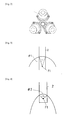
- FIG. 6 ( a ) First and third converging mirror-based furnaces of the present invention
- FIG. 6 ( b ) Conceptual drawing of the first and third converging mirror-based furnaces of the present invention
- FIG. 7 First and third converging mirror-based furnaces of the present invention
- FIG. 8 First and fourth converging mirror-based furnaces of the present invention
- FIG. 9 Drawing of optical path in the fourth converging mirror-based furnace of the present invention
- FIG. 10 Top view of the fourth converging mirror-based furnace of the present invention
- FIG. 11 Top view of the fourth converging mirror-based furnace of the present invention
- FIG. 12 Schematic illustration of crystal growth system using the system of the present invention
- the present invention in the case where an infrared lamp is used as a light source and infrared light is used as light is explained below by referring to the drawings.
- the structure of the present invention can also be adopted when other types of light source and light are adopted.
- the light used in the present invention in this case may include light other than infrared light.
- the first converging mirror-based furnace is a converging mirror-based furnace equipped with a structure that encompasses the second through fourth converging mirror-based furnaces explained below.
- the first converging mirror-based furnace is explained based on FIG. 1 ( a ).
- a first converging mirror-based furnace proposed by the present invention is a furnace that heats the surface of a target 3 by irradiating it with the light emitted from a light source that has been reflected using a reflecting mirror unit.
- the reflecting mirror unit is a unit comprising a primary reflecting mirror M 1 and secondary reflecting mirror M 2 , where an infrared lamp 2 or other light source is provided in the primary reflecting mirror M 1 and the light emitted from the light source is reflected by the interior surface of the primary reflecting mirror M 1 , after which the reflected light is guided into the secondary reflecting mirror M 2 and reflected by the reflecting surface on the interior surface of the secondary reflecting mirror M 2 to be released through an opening 5 and irradiated onto the surface of the target 3 .
- the converging mirror-based furnaces of the present invention can be used generally for systems for treatment involving heating, such as CVD systems and crystal growth systems. In particular, they can be used for applications where heating is achieved by light.
- the target is also a furnace that heats the target 3 by irradiating the target 3 with the light reflected by the reflecting surface of the secondary reflecting mirror.
- the target may be supplied with gas 104 from above or processed using a jig (not illustrated), or a window may be provided on its side so that the condition of the target 3 can be monitored while the target 3 is heated under desired conditions.
- a quartz pipe 207 is inserted between the converging mirror units and a polycrystal material bar 209 and seed crystal bar 210 are fixed to top and bottom fixing means 208 , respectively, and driven inside the pipe, as shown in Schematic Drawing 12 . Then, in the same manner as with the system shown in FIG. 1 ( a ) , infrared light irradiated from the infrared lamp 203 reflects on the primary reflecting mirror and secondary reflecting mirror and the polycrystal material bar 209 and seed crystal bar 210 move downward while being heated, to produce single crystal.
- the converging mirror-based furnace used in the present invention is a system that uses a light source that emits light and heats a target by the irradiated light.
- an infrared lamp generally is used for the light source, but it is not limited to the foregoing. Any light source that can be used for a furnace which uses light for heating can be used.
- the reflecting mirror unit of the present invention is comprised by the primary reflecting mirror and secondary reflecting mirror and the light source is installed in such a way that filaments, etc. are positioned inside the primary reflecting mirror.
- the primary reflecting mirror and secondary reflecting mirror are connected via openings provided in each reflecting mirror allowing light to pass through it. For this reason, the majority of the components of light emitted from the light source is reflected, first by the primary reflecting mirror and then by the secondary reflecting mirror, to be emitted outside the reflecting mirror unit and irradiated onto the target surface.
- the primary reflecting mirror is the primary reflecting mirror that reflects the light emitted from the light source and the secondary reflecting mirror is the secondary reflecting mirror that reflects the light reflected by the primary reflecting mirror.
- some of the light emitted from the light source may not be reflected by the primary reflecting mirror but is reflected by the secondary reflecting mirror directly, and then irradiated onto the target surface.
- some of the light emitted from the light source may be reflected neither by the primary reflecting mirror nor by the secondary reflecting mirror, but instead irradiated onto the target surface directly.
- the reflecting mirrors can be composed of publicly known materials and it is allowed to adopt any structures having publicly known reflectivity, including pure metallic base materials or metallic-base materials with another metal layer acting as a reflecting surface on the internal surface.
- the primary and secondary reflecting mirrors, and the reflecting mirror unit constituted by them may be manufactured by any relevant manufacturing method such as machining from blocks made of metal, etc., but they may also be manufactured by dividing each component into multiple blocks and manufacturing each block individually, and then assembling these blocks.
- light not irradiated onto the target surface from the perpendicular direction to the target surface means that light is irradiated onto the target surface from an oblique direction, in other words, at a finite angle.
- the secondary reflecting mirror If light is irradiated onto the target surface from the perpendicular direction to the target surface, the secondary reflecting mirror, or at least some part of it, has to be positioned at a location directly in front of the target surface in a manner facing it.
- the gas cannot be supplied smoothly if a part of the secondary reflecting mirror is located directly in front of the target surface.
- the present invention allows performing CVD, etc. smoothly.
- the target surface is not normally irradiated with the primary component of light from directly beside, or specifically from the direction of the plane that includes the target surface, because the target surface is not heated efficiently this way.
- FIGS. 1 ( a ) and 2 are drawings relating to a second converging mirror-based furnace proposed by the present invention, where FIG. 1 ( a ) is a section view showing an example of a converging mirror-based furnace using two sets or four sets of converging mirror units 7 .
- Spheroids whose interior surfaces provide reflecting surfaces to reflect the infrared light emitted from an infrared lamp 2 are used as a primary reflecting mirror M 1 and secondary reflecting mirror M 2 .
- FIG. 1 ( b ) The concept of the reflecting mirror unit used for this second converging mirror-based furnace is shown in FIG. 1 ( b ) .
- a light source is positioned at one focal point F 1 on the primary reflecting mirror M 1 whose reflecting surface is a spheroid.
- the light emitted from this light source is reflected by the primary reflecting mirror M 1 and forms an image at the other focal point F 2 .
- This focal point F 2 is the same as one focal point F 3 on the secondary reflecting mirror M 2 whose reflecting surface is a spheroid, and the light coupled at this focal point F 2 /F 3 diffuses again.
- the light forms an image at the other focal point F 4 on the secondary reflecting mirror, but this focal point F 4 can be adjusted to be positioned on the surface of the target 3 .
- these first and secondary reflecting mirrors are both a reflecting mirror whose reflecting surface is constituted by the interior surface of a spheroid formed around the long axis of a ellipsoidal body as its rotational axis, and the infrared light irradiated toward the target from the infrared lamp 2 provided at the focal point F 1 of the primary reflecting mirror is irradiated onto the target both directly and after being reflected by the reflecting surface.
- Converging mirror type furnace 1 of the present invention shown in FIG. 1 ( a ) is a system where the two focal points of the primary reflecting mirror M 1 and the two focal points of the secondary reflecting mirror M 2 are placed on a single straight line and the figure shows the primary reflecting mirror and secondary reflecting mirror are connected in a linear fashion.
- infrared light emitted from the infrared lamp 2 is first primarily reflected by the internal surface of the primary reflecting mirror M 1 .
- Infrared lamp 2 is installed inside the primary reflecting mirror M 1 such that the filament of the infrared lamp 2 is positioned at one focal point F 1 of the primary reflecting mirror M 1 .
- the infrared light reflected by the internal surface of the primary reflecting mirror M 1 converges at the other focal point F 2 of the spheroid.
- This other focal point F 2 where the infrared light converges represents the same position as one focal point F 3 of the secondary reflecting mirror M 2 , and therefore, considering the secondary reflecting mirror M 2 alone, it looks as if the filament of the infrared lamp were provided at one focal point F 3 . After converging at the one focal point F 3 , the infrared light diverges again and is reflected by the interior surface of the secondary reflecting mirror M 2 .
- the infrared light that has been reflected by the interior surface of the secondary reflecting mirror M 2 which is a spheroid, converges again at the other focal point F 4 of the secondary reflecting mirror M 2 .
- the target 3 is positioned at the other focal point F 4 of the secondary reflecting mirror M 2 , said target is rapidly heated to high temperatures by the converged infrared light.
- the secondary reflecting mirror M 2 must be provided with a connection part 4 for connecting to the primary reflecting mirror M 1 to provide an optical path needed to introduce infrared light from the primary reflecting mirror M 1 , and the secondary reflecting mirror M 2 must also be provided with an opening 5 through which to irradiate infrared light toward the target 3 in such a way that the other focal point F 4 of the secondary reflecting mirror M 2 is positioned on the surface of the target 3 or along a straight line connecting the center of the target surface and one focal point F 3 of the secondary reflecting mirror.
- the area of the interior surface of the primary reflecting mirror M 1 and the secondary reflecting mirror M 2 must be made as large as possible in order to use the infrared light emitted from the infrared lamps 2 as the energy to heat the target 3 as effectively as possible.
- the target material to be irradiated is small, the smaller the aperture of the opening 5 in the secondary reflecting mirror is, the better. For this reason, it is desired to make the shape of the secondary reflecting mirror M 2 as elongated as possible.
- the infrared lamp 2 when the infrared lamp 2 is installed on one focal point F 1 of the primary reflecting mirror M 1 , as much as possible, the closer to 1 the ratio of the long axis to the short axis of the ellipse of the primary reflecting mirror M 1 is, the more the infrared light emitted from the focal point is partially absorbed by the infrared lamp itself as the infrared lamp 2 itself acts as an obstruction as shown in FIG. 3 , or the smaller the amount of main light beam which is not reflecting becomes. Consequently, more infrared light hits the interior surface of the primary reflecting mirror M 1 and is reflected thereby, and it becomes possible to be guided toward the secondary reflecting mirror M 2 .
- the primary reflecting mirror M 1 becomes closer to a sphere when the aforementioned ratio gets too close to 1, in which case an ellipse shape capable of supplying a sufficient amount of infrared light toward the secondary reflecting mirror M 2 may not be retained.
- FIG. 3 provides a schematic illustration of an example where the ratio of the major axis to the minor axis of the ellipse of the primary reflecting mirror M 1 is small and closer to 1, and as for the infrared light emitted from the filament of the infrared lamp provided at one focal point F 1 , only those components of infrared light having a heading angle ⁇ 1 clearly smaller than 60° are emitted toward the infrared lamp 2 itself, and the remaining components of infrared light over a wide range exceeding 300° can be reflected by the interior surface of the primary reflecting mirror M 1 .
- FIG. 4 that also provides a schematic illustration, the shape of the primary reflecting mirror M 1 becomes long and thin with the focal point positioned close to the interior surface, when the ratio of the major axis to the minor axis of the ellipse of the primary reflecting mirror M 1 is large.
- installing the infrared lamp 2 at one focal point F 1 results in noticeably more of the emitted infrared light than in the example shown in FIG. 3 , or specially those components emitted over a wider angle ⁇ 2 fail to reach the reflecting surface, and in FIG. 4 , only the infrared light in a range of approx. 250° reaches the reflecting surface.
- This ratio of the major axis to the minor axis of the primary reflecting mirror M 1 is preferably 1.1 to 2.0, or more preferably 1.1 to 1.5.
- the secondary reflecting mirror M 2 is provided with an opening 5 through which to emit infrared light toward the target 3 as mentioned above.
- the opening 5 is not provided in the secondary reflecting mirror M 2 simply to emit infrared light, but it must be provided by considering the size, position, moving range, and other specifics of the quartz pipe 6 , etc.
- the opening 5 provided in consideration of these items is made as small as possible. This way, components of infrared light that come out of the reflecting mirror M 2 and diverge without irradiating the target 3 can be reduced, and consequently more infrared light can be irradiated onto the target 3 to contribute to the raising of its temperature. In addition, components of infrared light that do not irradiate the target 3 but heat the surroundings can also be reduced.
- an opening 5 can be provided to the extent that the applicable treatment means does not interfere with the secondary reflecting mirror M 2 .
- the secondary reflecting mirror M 2 can be installed in such a way that the other focal point F 4 of the secondary reflecting mirror M 2 is positioned on the target or in such a way that F 4 is not positioned on the target 3 , as long as the center of the surface of the target 3 is positioned on the straight line connecting the two focal points of the secondary reflecting mirror M 2 .
- the filament of the infrared lamp 2 forms an image on the surface of the target 3 to make uniform heating difficult, it is possible to not position the other focal point F 4 on the target 3 , but to position the center of the target 3 on a straight line connecting the center of the target 3 and two focal points F 3 and F 4 of the secondary reflecting mirror M 2 to purposely achieve a defocusing effect, while positioning the other focal point of the secondary reflecting mirror M 2 not on the target 3 , so as to achieve more uniform heating in the range where an image of the filament does not form.
- FIG. 2 is a top view outlining another example of a converging mirror-based furnace conforming to the present invention, where three converging mirror units 7 are provided and certain means (not illustrated) are used to make these converging mirror units 7 and/or the target movable in vertical and horizontal directions as desired, which makes it possible to adjust the position relationship of the center of the target surface and the other focal point of the secondary reflecting mirror. Also in FIG. 2 , space is made among the three converging mirror units 7 and, if necessary, a unit for cooling the converging mirror units 7 or unit for transporting, treating, or otherwise manipulating the target can be installed in this space.
- FIG. 5 shows another embodiment of a converging mirror-based furnace conforming to the present invention.
- This converging mirror-based furnace shown in FIG. 5 has the same basic structure as that of the converging mirror-based furnace shown in FIGS. 1 ( a ) and 2 , but it is different in terms of the type of connection between the primary reflecting mirror M 3 and secondary reflecting mirror M 4 .
- the focal points of the spheroids constituting the primary reflecting mirror M 3 and secondary reflecting mirror M 4 are not positioned along one straight line, but the primary reflecting mirror M 3 is bent upward and connected to the secondary reflecting mirror M 4 , and consequently in this example, the two straight lines including the straight line connecting the focal points of the ellipse of the primary reflecting mirror M 3 and the straight line connecting the focal points of the ellipse of the secondary reflecting mirror M 4 are not on the same straight line.
- This example is different from the system illustrated in FIGS. 1 ( a ) and 2 where the two straight lines are on the same straight line.
- This type of arrangement makes it possible to reduce the size of the converging mirror-based furnace 1 in the width direction, and when the primary reflecting mirror M 3 and the infrared lamp 2 to be used are installed vertically, replacement of the infrared lamp 2 and other maintenance tasks required by the system can be performed from above, which makes these tasks easier to perform and/or improves the ease of installing a cooling unit.
- the height of the reflecting mirror unit as a whole can be lowered when the primary reflecting mirror M 3 is not erected, but laid flat laterally, as shown in FIG. 5 , and because installing the infrared lamp directly beside the primary reflecting mirror M 3 also becomes possible, maintenance tasks can be performed more easily from the side, and the ease of installing a cooling unit also improves.
- FIGS. 6 ( a ) and 7 As can be seen in the illustrations, it basically adopts the same configuration as that of the second converging mirror-based furnace shown in FIGS. 1 ( a ) and 5 ; with the third converging mirror-based furnace 1 , however, the secondary reflecting mirrors M 2 and M 4 used by the second converging mirror-based furnace 1 are replaced with revolving paraboloidal mirror M 5 or M 6 instead of the revolving ellipsoidal mirrors.
- FIG. 6 ( b ) The concept of the reflecting mirror unit used for this third converging mirror-based furnace is shown in FIG. 6 ( b ) .
- the light source is positioned at one focal point F 1 of the primary reflecting mirror M 1 whose reflecting surface is a spheroid.
- the light emitted from this light source is reflected by the primary reflecting mirror M 1 and forms an image at the other focal point F 2 .
- This focal point F 2 is the same as the focal point F 3 of the secondary reflecting mirror M 2 whose reflecting surface is a revolving paraboloidal body, and the light coupled at this focal point F 2 or F 3 diffuses again.
- the diffused light is then reflected by the secondary reflecting mirror and becomes parallel light, and this parallel light is irradiated onto the surface of the target 3 .
- the focal point F 3 of the revolving paraboloidal mirrors M 5 and M 6 is the same as the other focal point of the primary reflecting mirrors M 1 and M 3 , the infrared light emitted by the infrared lamp is introduced to the secondary reflecting mirror M 5 or M 6 which is a revolving paraboloidal mirror, as is the case with the second converging mirror-based furnace.
- This infrared light that has been introduced to the focal point of the revolving paraboloidal mirrors constituting the secondary reflecting mirrors M 5 and M 6 is emitted directly from the target-side opening 5 in the secondary reflecting mirror M 5 or M 6 , or is reflected by the interior surface of the secondary reflecting mirror M 5 or M 6 and then emitted from the target-side opening 5 .
- this third converging mirror-based furnace 1 also requires that the target-side opening 5 in the secondary reflecting mirrors M 5 and M 6 be provided not just to emit infrared light, but also by considering the quartz pipe and other members supplied with the system as well as the size, position or movement of the equipment, among other considerations.
- the target-side opening 5 provided in consideration of the aforementioned items, is positioned as far away as possible from the focal point from the viewpoint of reducing the quantity of diverging infrared light output from the secondary reflecting mirrors M 5 and M 6 so as to irradiate more infrared light onto the target to help raise its temperature.
- the third converging mirror-based furnace 1 proposed by the present invention is also such that space is made between the converging mirror units 7 and therefore, if necessary, a unit for cooling the converging mirror units 7 or unit for transporting, treating, or otherwise manipulating the target can be installed in this space.
- a fourth converging mirror-based furnace is explained using FIG. 8 .
- the fourth converging mirror-based furnace proposed by the present invention is a converging mirror-based furnace where a ring-shaped reflecting surface is formed which in turn forms a primary reflecting mirror constituted by a closed space such as an ellipsoid, etc., and an infrared lamp is installed in the closed space.
- a slit that forms a secondary reflecting surface of a shape constituting a paraboloidal surface, etc.
- the infrared light emitted from the infrared lamp 103 is directly irradiated onto the target or reflected by a mirror constituted by a ring-shaped reflecting surface or paraboloidal surface and then irradiated onto the target.
- the system basically designed as mentioned above, may also be structured in such a way that the reflecting surface is formed as a ring surrounding the gas flow channel or quartz pipe or other pipe 107 .
- FIG. 8 is a concept section view of an example of the fourth converging mirror-based furnace whose reflecting surface is the interior surface provided to reflect the infrared light emitted from the infrared lamp 103 .
- the ring shape constituted by a combination of a reflecting surface 106 whose section is an ellipsoid or other closed reflecting surface 106 with a paraboloidal surface 111 whose section is a parabola (hereinafter referred to as “ring-shaped reflecting surface”) is such that the reflecting surface 106 shown is a part of the ring-shaped reflecting surface and the infrared light emitted from the infrared lamp 103 toward the target is irradiated directly, or reflected by the ring-shaped reflecting surface and then irradiated, onto the target 102 .
- This slit 111 constituted by the ellipsoid or other reflecting surface 106 or paraboloidal surface, etc., is different from the aforementioned second or third converging mirror-based furnace in that it is not a revolving ellipsoid or revolving paraboloidal surface obtained by rotating around the line connecting the two focal points of the ellipse or symmetrical axis of the parabola, but it is an ellipsoid or other donut-shaped space or paraboloidal surface obtained by rotating around a rotational axis not intersecting with the ellipse or axis intersecting at an angle with the symmetrical axis of the parabola.
- the entire surface of the target 102 must be heated uniformly and therefore the infrared light reflected by the ellipsoid or other reflecting surface 106 can be caused to diffuse to a certain extent, instead of simply forming a focus on the surface of the target 102 .
- the light can also be caused to form a focus on the target so long as it can uniformly heat the entire surface of the target 102 .
- the infrared light emitted toward the other focal point closer to the target forms a focus when the infrared lamp 103 is positioned at, of the focal points of the ellipse, the focal point farther away from the target.
- the heating temperature would vary on the surface of the target 102 should a focus be formed on the target by assuming that the surface of the target 102 provides the other focal point, and consequently proper treatment cannot be performed.
- a ring-shaped reflecting surface can be constituted basically with a revolving ellipsoid obtained by rotating an ellipse around a rotational axis provided outside the ellipse, in order to irradiate infrared light without causing it to form a focus on the target surface, because there is no need for the light to form a focus on the surface of the target 102 .
- the ellipse is not the only option and any closed curved line or other closed line can be used.
- the reflecting surface 106 of the converging mirror-based furnace 101 proposed by the present invention is a ring-shaped reflecting surface constituted by a combination of a revolving ellipsoidal mirror with a revolving paraboloidal mirror, and it draws a closed curved line surrounding the infrared lamp 103 in a section sliced by a plane that passes through the center of the two mirrors and lies perpendicular to the ring.
- this infrared lamp 103 is caused to emit infrared light from a filament in the lamp, where the filament is not a point light source, but a surface light source or line light source to some extent.
- the ring-shaped reflecting surface constituted by a combination of a revolving ellipsoidal mirror with a revolving paraboloidal mirror is such that, as the ellipse is inclined toward the target, the parabola is also inclined to create an opening facing the target.
- a slit 111 constituted by a revolving paraboloidal surface is provided to let the infrared light pass through, at a location near the point of intersection between the line connecting one focal point and the other focal point of the ellipse on which the infrared lamp 103 as well as the center of the target 102 on one hand, and the line that draws the ellipse on the other, and the ellipse is cut at the location of this slit 111 and the target is installed along a line extended from the slit 111 as viewed from the infrared lamp 103 .
- the light emitted in each direction from the infrared lamp 103 is irradiated onto the target 102 with a small number of reflections on the ring-shaped reflecting surface 106 .
- the cross section of the ring-shaped reflecting surface 106 preferably has an ellipse shape as mentioned above, but it can also have any other similar shape.
- some infrared light may follow an optical path that is reflected by the wall of the slit 111 constituting the paraboloidal surface shown in FIG. 8 and then is irradiated onto the target 102 .
- a quartz pipe or other pipe 107 can be installed in such a way that it passes through the center of the ring of the ring-shaped reflecting surface at the center of the converging mirror-based furnace 101 , as is the case with the second or third converging mirror-based furnace.
- gas 104 can be supplied toward the target through the pipe 107 from above or below during, before, or after heating.
- the target can be positioned inside this pipe 107 or the end of the pipe 107 can be positioned above or below the target.
- the target can be processed using a jig (not illustrated) or a window can be provided on the side so that the condition of the target 102 can be monitored while the target 102 is being heated under any desired condition.
- FIG. 9 An example of a specific reflecting surface used by the converging mirror-based furnace 101 shown in FIG. 8 is illustrated in the schematic drawing of FIG. 9 .
- the reflecting surface shown in FIG. 9 has a shape constituted by combining the ring-shaped reflecting surface 106 or another ellipsoidal mirror whose focal points are F 5 and F 6 and whose cross section is an ellipse, and a slit 111 of paraboloidal mirror, etc. which is a secondary reflecting mirror M 8 whose cross section is the parabola in FIG. 8 and shares one focal point F 6 of the ellipse.
- the ring-shaped reflecting surface M 7 is an ellipse
- the part of the ring-shaped reflecting surface M 7 indicated by the solid line is where a mirror is constituted to reflect infrared light
- the part indicated by the broken line is not actually a mirror, but it forms an opening instead, representing a part of the ellipse drawn to indicate that this reflecting surface is an ellipsoidal mirror in FIG. 9 .
- the part indicated by the solid line is where a mirror is constituted to reflect infrared light
- the part indicated by the broken line is not actually a mirror, but it constitutes a parabola instead, representing a part of the parabola drawn to indicate that the slit 111 is a paraboloidal mirror in FIG. 9 .
- FIG. 9 different paths are shown through which the infrared light emitted from the infrared lamp installed at F 5 is emitted toward the target from the reflecting mirror.
- the infrared light emitted from the infrared lamp is partially irradiated directly onto the target without being reflected by the interior surface of the slit 111 or after reflecting and then passing through the slit 111 as parallel light.
- the majority of the infrared light emitted from the infrared lamp hits the ring-shaped reflecting surface M 7 and reflects at least once by the rotating paraboloidal surface of M 8 being the secondary reflecting mirror, and then passes through the slit 111 and is irradiated onto the target 102 .
- (b) shows an optical path where the infrared light emitted toward the opposite side of the slit 111 from the infrared lamp installed at F 5 is reflected by the ring-shaped reflecting surface M 7 being an ellipsoidal mirror, etc., and then directly travels or is reflected by the slit 111 and travels toward the target.
- (c) shows an optical path where infrared light is emitted from the infrared lamp installed at F 5 toward a direction lateral to the infrared lamp other than the direction in (a) or (b), wherein the infrared light is not reflected by the ring-shaped reflecting surface M 7 being an ellipsoidal mirror, etc, and then directly irradiated onto the target, but it reflects at least once on the slit 111 and then is irradiated onto the target.
- the cross section of the ring-shaped reflecting surface M 7 is a combination of the ring-shaped reflecting surface and the slit, and the infrared lamp 103 is installed at the focal point of this ring-shaped reflecting surface being an ellipsoidal, etc., or other position not exactly on the focal point but close to the focal point. Because the target is not positioned at the other focal point of the ellipse, etc., however, the light reflected by the ring-shaped reflecting surface M 7 does not form a focus on the surface-to-be-heated of the target 102 , but it hits the surface of the target 102 uniformly, and consequently the shape of the coil of the infrared lamp is not casted on the target 102 .
- the ring-shaped reflecting surface shown in FIGS. 8 and 9 is an ellipse, it can also have a non-ellipse shape which is based on this ellipse shape but whose surface is partially constituted by a straight line, etc.
- the subject shown in FIG. 9 also applies correspondingly to the optical paths of light with the first through third converging mirror-based furnaces.
- FIG. 10 is a drawing illustrating a combination of members that constitute a ring-shaped reflecting surface, as viewed from the bottom, where the right side specifically provides a section view cut at the infrared lamp 103 .
- the ring-shaped reflecting surface may not be a completely closed ring, but two ring-shaped reflecting surfaces 106 may be provided that each are of roughly one half the size and capable of accommodating one of the two infrared lamps 103 each connected to a power cable, and the infrared lamps 103 are respectively fixed by members (not illustrated).
- the ring shape does not necessarily mean a complete ring of 360°, but the ring may be cut near the bent part of the infrared lamp in some cases to allow for assembly of or to accommodate the infrared lamp structure of the system, but it is necessary to not cut the ring at too many locations around its 360° perimeter to prevent uneven heating of the surface-to-be-heated.
- the area constituted by the ring-shaped reflecting surface 106 can also be provided with an inlet and outlet to supply and discharge cooling air to prevent overheating of the high-temperature heating path itself during heating.
- a slit that extends along the circumferential direction of the ring-shaped reflecting surface is formed on the bottom surface.
- the ring-shaped reflecting surface 106 under the present invention is such that the diameter of the ring constituted by the reflecting surface is 120 to 160 mm, while the section of the ring-shaped reflecting surface cut by a plane passing through the center of the ring and perpendicular to the ring is 45 to 55 mm in the long-axis direction and 35 mm to 45 mm in the short-axis direction. If both dimensions are too small, the infrared lamp cannot be inserted with a sufficient distance kept from the reflecting surface, but if these dimensions are too large, reducing the size of the converging mirror-based furnace itself may become difficult. Basically, a reflecting surface of the aforementioned size is sufficient, even when heating to 2000° C. or above is required within several seconds, although the specific size varies depending on the output of the infrared lamp.
- the member constituting the ring-shaped reflecting surface 106 may be made of aluminum alloy, etc., where the constituent metal member is stable, does not expand much under heat, and has excellent heat resistance. Accordingly, preferably the member constituting the ring-shaped reflecting surface 106 is also a ring-shaped metal member and plated with gold offering high reflecting efficiency with respect to infrared light. For this reason, a quartz pipe, etc., may be inserted at the center of the ring to generate single crystal inside the quartz pipe, for example. It is also possible to apply CVD or other treatment.
- the ring-shaped metal member itself has an outer diameter of 190 to 230 mm or preferably 200 to 220 mm and a thickness of 60 to 80 mm or preferably 65 to 75 mm, and the hole at its center has a diameter of 30 to 40 mm.
- the range of outer diameters reflects the size of the ring-shaped reflecting surface 106 to be formed inside, plus the thickness of the metal member, etc., while the range of thicknesses also represents the thickness of the ring-shaped reflecting surface 106 plus the thickness of the metal member, etc.
- the outer diameter of the hole at the center of the ring-shaped metal member must be large enough for a quartz pipe or other member to run through it.
- the aforementioned slit provided in the ring-shaped reflecting surface 106 is formed by a parabola line in such a way that the target can be heated uniformly, or specifically to allow the line connecting the infrared lamp 103 and target to pass through it. And, as with the surface of the ring-shaped reflecting surface 106 , the interior surface of the slit is also plated or otherwise coated with gold or other material offering high reflectance with respect to infrared light so as to reflect infrared light.
- this slit must be extended as close as possible to the target in order to irradiate more infrared light onto the target. For this reason, the bottom part of the ring-shaped metal member where the slit is made is formed to be extendable.
- the shortest straight distance between the infrared lamp 103 and the center of the target is 70 to 95 mm, or preferably 75 to 90 mm, while the shortest straight distance from the top of the slit is 30 mm to 40 mm.
- the converging mirror-based furnace proposed by the present invention is constituted in such a way that the surface of the horizontally set target is heated by the infrared light irradiated at an angle of 20 to 70°. If this angle is less than 20°, the infrared light emitted from the ring-shaped reflecting surface cannot be irradiated onto the target efficiently and there is a possibility that the infrared light may miss the target and irradiate other members. If the angle is 70° or greater, on the other hand, it becomes difficult to secure space in which to install a jig or gas supply device vertically above the target.
- one infrared lamp 103 with a power cable 112 is installed on each half of the ring-shaped reflecting surface, and both ends of the infrared lamp 103 are fixed to the furnace.
- the target can be irradiated with infrared light virtually from all directions when two infrared lamps 103 are installed.
- the number of infrared lamps 103 need not be two, but one, three or more infrared lamps 103 may be installed to the extent possible to cover as much circumference as possible.
- the ring-shaped reflecting surface 106 and ring-shaped metal member are heated by absorbing the infrared light from the infrared lamp during operation, so it is essential that a cooling unit be installed in the converging mirror-based furnace.
- the ring-shaped reflecting surface 106 and other units are explained by referring to FIG. 8 again.
- a groove is provided beforehand for a cooling jacket 113 to pass cooling water on the exterior surface of the ring-shaped metal member to cool the ring-shaped metal member constituting the ring-shaped reflecting surface 106 , and subsequently a cooling jacket 113 is formed between the groove and a lid member 114 to be installed, and a cooling-water supply pipe 115 is connected to the jacket via a cooling-water supply port 116 .
- cooling water is passed only on the top surface of the ring-shaped metal member here, a structure may be provided to pass cooing water in other areas such as along the circumference of the ring-shaped metal member.
- FIG. 11 shows a top view of the converging mirror-based furnace 101 conforming to the present invention.
- the cooling-water supply pipe 115 and cooling-water drain pipe 117 are connected to the circular top face of the converging mirror-based furnace 101 via the cooling-water supply port 116 and cooling-water drain port 118 , respectively.
- the line enclosing the largest area indicates the position of the ring-shaped reflecting surface 106 , although it is not visible from the top face, while the area enclosed by the inner broken line indicates the cooling jacket 113 .
- Drained water is supplied to the radiator (not illustrated) and air-cooled there by air for cooling. Following the circulation path, this cooled water is again supplied to the cooling jacket via the cooling-water supply pipe connected to the furnace.
- fresh cooling water may be supplied from the outside instead of supplying recirculated water to the radiator, but this requires connecting a pipe to supply cooling water from outside of the system and this may limit the installation location of the furnace; accordingly, it is preferable to circulate cooling water with a pump via a radiator or other cooling unit.
- the infrared lamp 103 is preferably a halogen lamp, although any known infrared lamp can be used, and the infrared lamp 103 may be of the type that emits infrared light using filaments.
- an opening may be provided, on the member securing the infrared lamp 103 onto the ring-shaped reflecting surface 106 , for example, in order to introduce or discharge air for cooling the interior of the ring-shaped reflecting surface 106 .
- cooling air passes through the space between the infrared lamp 103 and ring-shaped reflecting surface and cools both, which means that the supplied cooling air is used for cooling in an efficient manner.
- the second and third converging mirror-based furnaces proposed by the present invention have a structure where the furnace is supported by supporting members inside a frame cover, as is the case with known furnaces, and the frame cover that accommodates the converging mirror-based furnace comprises a top panel, front door, side panels, rear panel, and bottom panel, and the front door is opened and closed to insert and remove a target, etc.
- the top panel can have an opening through which to insert a quartz pipe or other long member to be used to generate single crystal, while the top panel, side panels, rear panel, and bottom panel can have an opening through which to pass the power cable for the infrared lamp, pipe for supplying and discharging cooling water, pipe for supplying and discharging the processing gas to be circulated inside the converging mirror-based furnace, and, if both the infrared lamp and reflecting surface are to be cooled with cooling air, pipe for supplying and discharging this cooling air.
- the frame cover can also be provided with a sight glass so that the target can be observed from outside the system.
- the frame cover accommodating the converging mirror-based furnace proposed by the present invention may be installed on a base.
- the base can have various units for operating the furnace installed in it, such as a power supply, controller, and radiator for the furnace, unit for circulating cooling water, unit for supplying cooling air, and unit for moving the target.
- a quartz pipe 207 is inserted into the ring-shaped reflecting surface 206 in a manner penetrating through the center of the ring, and a polycrystal material bar 209 and seed crystal bar 210 are fixed to top and bottom fixing means 208 which is driven inside the pipe, as shown in the schematic drawing of FIG. 12 .
- the infrared light emitted from the infrared lamp 203 reflects on the ring-shaped reflecting surface 206 and heats the polycrystal material bar 209 and seed crystal bar 210 , and while being heated this way, these material bar 209 and seed crystal bar 210 move downward to generate single crystal.
- the present invention is structurally different from a conventional system that heats the target from the side by reflecting infrared light on a revolving ellipsoid, and accordingly the target being heated can be monitored from its side and the operating status of the CVD furnace or single crystal growth system, whichever the case may be, can be monitored during heating.
- the infrared lamp 203 and ring-shaped reflecting surface 206 can be positioned above the target, which in turn allows for using a ring-shaped reflecting surface 206 smaller than what is required when the conventional revolving ellipsoid is used, thereby reducing the space between the infrared lamp 203 and ring-shaped reflecting surface 206 on one hand and the target on the other.
- a quartz pipe 207 is inserted into the hole at the center of the ring-shaped metal member on which the ring-shaped reflecting surface 206 is provided, and, for example, the target is securely inserted into the bottom end of the opening of the quartz pipe 207 and fixed at a position to which the infrared light from the infrared lamp 203 is emitted.
- the space inside the quartz pipe 207 is replaced with treatment gas or treatment gas is supplied through the pipe, or cooling water is supplied and circulated through a cooling jacket, and air to cool the infrared lamp 203 is introduced and circulated from the part where the infrared lamp 203 is fixed.
- the power to the infrared lamp 203 is turned on to start heating and the temperature is controlled, and the moment the specified treatment is given, the heating temperature is lowered. After the treatment, the target is removed from the bottom end of the quartz pipe 207 and transferred to the next treatment process.
- the next target is inserted from the bottom end of the quartz pipe 207 , fixed, and then heated, instead of stopping the supply of cooling water or air.
- use of the quartz pipe 207 is not a requirement and whether or not to use the pipe can be determined as desired according to the necessity.
- the target to be heated by the converging mirror-based furnace proposed by the present invention may be glass, semiconductor material, metal, ceramic, resin, or any other object normally processed by means of heating.
- the furnace can also be used for some manufacturing processes for LSIs, MEMS, etc.
- it can be used as a deposition system, CVD furnace, single-crystal manufacturing system, or other system that involves heating.
- the size of the target is determined by the specific application to some extent; on the other hand, the present invention allows for treatment of targets of any size, but preferably those of 50 mm or less in diameter, or more preferably those of 30 mm or less in diameter, or most preferably those of 15 mm or less in diameter, as these dimensions make suitable targets.
- the target can have any shape so long as the surface irradiated by light is flat, and a non-flat surface is also acceptable to the extent that the object of the present invention is met.
- the target surface can be heated to 2000° C. or above in several seconds after the start of heating, meaning that the speed of heat-treating the target can be improved.
Landscapes
- Engineering & Computer Science (AREA)
- Chemical & Material Sciences (AREA)
- Mechanical Engineering (AREA)
- Physics & Mathematics (AREA)
- Toxicology (AREA)
- Health & Medical Sciences (AREA)
- General Engineering & Computer Science (AREA)
- Materials Engineering (AREA)
- Metallurgy (AREA)
- Organic Chemistry (AREA)
- General Physics & Mathematics (AREA)
- Power Engineering (AREA)
- Condensed Matter Physics & Semiconductors (AREA)
- Manufacturing & Machinery (AREA)
- Computer Hardware Design (AREA)
- Microelectronics & Electronic Packaging (AREA)
- General Chemical & Material Sciences (AREA)
- Chemical Kinetics & Catalysis (AREA)
- Electromagnetism (AREA)
- Crystallography & Structural Chemistry (AREA)
- Control Of Resistance Heating (AREA)
- Furnace Details (AREA)
- Muffle Furnaces And Rotary Kilns (AREA)
- Optical Elements Other Than Lenses (AREA)
Applications Claiming Priority (4)
| Application Number | Priority Date | Filing Date | Title |
|---|---|---|---|
| JP2011264939 | 2011-12-02 | ||
| JP2011264939 | 2011-12-02 | ||
| JP2011-264939 | 2011-12-02 | ||
| PCT/JP2012/081093 WO2013081107A1 (ja) | 2011-12-02 | 2012-11-30 | 集光鏡加熱炉 |
Publications (2)
| Publication Number | Publication Date |
|---|---|
| US20140338591A1 US20140338591A1 (en) | 2014-11-20 |
| US9777375B2 true US9777375B2 (en) | 2017-10-03 |
Family
ID=48535555
Family Applications (1)
| Application Number | Title | Priority Date | Filing Date |
|---|---|---|---|
| US14/362,348 Active 2033-12-03 US9777375B2 (en) | 2011-12-02 | 2012-11-30 | Converging mirror furnace |
Country Status (5)
| Country | Link |
|---|---|
| US (1) | US9777375B2 (zh) |
| JP (1) | JP5765750B2 (zh) |
| KR (1) | KR101677819B1 (zh) |
| CN (1) | CN104011491B (zh) |
| WO (1) | WO2013081107A1 (zh) |
Cited By (1)
| Publication number | Priority date | Publication date | Assignee | Title |
|---|---|---|---|---|
| US20170082488A1 (en) * | 2014-02-03 | 2017-03-23 | Korea National University Of Transportation Industry-Academic Cooperation Foundation | Optical wave guide having multiple independent optical path and optical gas sensor using that |
Families Citing this family (6)
| Publication number | Priority date | Publication date | Assignee | Title |
|---|---|---|---|---|
| DE102013113600B4 (de) | 2013-12-06 | 2021-09-23 | Technische Universität Dresden | Prüfvorrichtung und hochfokussierende Heizvorrichtung zur Erzeugung hoher Wärmestromdichten |
| UA119264C2 (uk) * | 2014-08-03 | 2019-05-27 | Прадіп Металс Лімітед | Мікрохвильова піч комбінованого нагрівання |
| JP6732235B2 (ja) * | 2014-12-02 | 2020-07-29 | 国立研究開発法人産業技術総合研究所 | 集光鏡方式加熱炉 |
| CN108028214B (zh) * | 2015-12-30 | 2022-04-08 | 玛特森技术公司 | 用于毫秒退火系统的气体流动控制 |
| US11654629B2 (en) * | 2018-10-26 | 2023-05-23 | Hewlett-Packard Development Company, L.P. | Mirror assemblies for three dimensional printers |
| CN109548222B (zh) * | 2019-01-17 | 2024-04-12 | 西南石油大学 | 一种加热装置及用于制备长线材超导体的综合热处理系统 |
Citations (14)
| Publication number | Priority date | Publication date | Assignee | Title |
|---|---|---|---|---|
| JPS62292265A (ja) | 1986-06-11 | 1987-12-18 | Hitachi Ltd | 光ビ−ム式加熱装置 |
| JPS63986A (ja) | 1986-06-18 | 1988-01-05 | 株式会社日立製作所 | 加熱装置 |
| JPH05205852A (ja) | 1992-01-23 | 1993-08-13 | Seiko Instr Inc | 赤外線加熱装置 |
| JPH11255593A (ja) | 1998-03-12 | 1999-09-21 | Super Silicon Kenkyusho:Kk | 原料溶解補助装置 |
| US6033470A (en) * | 1996-03-22 | 2000-03-07 | Murata Manufacturing Co., Ltd. | Method of producing a cerium-containing magnetic garnet single crystal |
| JP2000223488A (ja) | 1999-01-28 | 2000-08-11 | Nec Corp | 半導体装置の製造方法 |
| JP2001165878A (ja) | 1999-12-14 | 2001-06-22 | Tostech:Kk | 赤外線高温加熱炉 |
| US20020112659A1 (en) * | 2001-02-21 | 2002-08-22 | Murata Manufacturing Co., Ltd. | Single crystal and method of manufacturing same |
| JP3668738B1 (ja) | 2004-02-09 | 2005-07-06 | Necマシナリー株式会社 | 単結晶育成装置 |
| JP2005195685A (ja) | 2003-12-26 | 2005-07-21 | Unitec:Kk | 反射光学系、拡散光源測定装置の反射光学系および拡散光源測定装置ならびにその測定方法 |
| WO2005075713A1 (ja) | 2004-02-05 | 2005-08-18 | Nec Machinery Corporation | 単結晶育成装置 |
| JP2007145611A (ja) | 2005-11-24 | 2007-06-14 | National Institute Of Advanced Industrial & Technology | サファイア単結晶製造方法及びその製造装置 |
| JP2008107050A (ja) | 2006-10-27 | 2008-05-08 | Iwasaki Electric Co Ltd | 高温加熱炉 |
| CN101611177A (zh) | 2007-01-10 | 2009-12-23 | 株式会社水晶系统 | 浮区熔化装置 |
Family Cites Families (2)
| Publication number | Priority date | Publication date | Assignee | Title |
|---|---|---|---|---|
| JP4405320B2 (ja) | 2003-06-12 | 2010-01-27 | 古河機械金属株式会社 | 赤外線加熱単結晶製造装置 |
| JP5481715B2 (ja) * | 2007-10-22 | 2014-04-23 | 株式会社ブイ・テクノロジー | レーザ加工装置及びレーザ加工方法 |
-
2012
- 2012-11-30 CN CN201280059406.6A patent/CN104011491B/zh active Active
- 2012-11-30 WO PCT/JP2012/081093 patent/WO2013081107A1/ja active Application Filing
- 2012-11-30 US US14/362,348 patent/US9777375B2/en active Active
- 2012-11-30 JP JP2013547235A patent/JP5765750B2/ja active Active
- 2012-11-30 KR KR1020147015047A patent/KR101677819B1/ko active IP Right Grant
Patent Citations (17)
| Publication number | Priority date | Publication date | Assignee | Title |
|---|---|---|---|---|
| JPS62292265A (ja) | 1986-06-11 | 1987-12-18 | Hitachi Ltd | 光ビ−ム式加熱装置 |
| JPS63986A (ja) | 1986-06-18 | 1988-01-05 | 株式会社日立製作所 | 加熱装置 |
| JPH05205852A (ja) | 1992-01-23 | 1993-08-13 | Seiko Instr Inc | 赤外線加熱装置 |
| US6033470A (en) * | 1996-03-22 | 2000-03-07 | Murata Manufacturing Co., Ltd. | Method of producing a cerium-containing magnetic garnet single crystal |
| JPH11255593A (ja) | 1998-03-12 | 1999-09-21 | Super Silicon Kenkyusho:Kk | 原料溶解補助装置 |
| JP2000223488A (ja) | 1999-01-28 | 2000-08-11 | Nec Corp | 半導体装置の製造方法 |
| JP2001165878A (ja) | 1999-12-14 | 2001-06-22 | Tostech:Kk | 赤外線高温加熱炉 |
| US20020112659A1 (en) * | 2001-02-21 | 2002-08-22 | Murata Manufacturing Co., Ltd. | Single crystal and method of manufacturing same |
| JP2005195685A (ja) | 2003-12-26 | 2005-07-21 | Unitec:Kk | 反射光学系、拡散光源測定装置の反射光学系および拡散光源測定装置ならびにその測定方法 |
| US20070131162A1 (en) | 2004-02-05 | 2007-06-14 | Nec Machinery Corporation | Single crystal growing apparatus |
| WO2005075713A1 (ja) | 2004-02-05 | 2005-08-18 | Nec Machinery Corporation | 単結晶育成装置 |
| JP3668738B1 (ja) | 2004-02-09 | 2005-07-06 | Necマシナリー株式会社 | 単結晶育成装置 |
| JP2007145611A (ja) | 2005-11-24 | 2007-06-14 | National Institute Of Advanced Industrial & Technology | サファイア単結晶製造方法及びその製造装置 |
| JP2008107050A (ja) | 2006-10-27 | 2008-05-08 | Iwasaki Electric Co Ltd | 高温加熱炉 |
| CN101611177A (zh) | 2007-01-10 | 2009-12-23 | 株式会社水晶系统 | 浮区熔化装置 |
| KR20100004937A (ko) | 2007-01-10 | 2010-01-13 | 크리스탈 시스템스 코포레이션 | 부유대역용융장치 |
| US20100037817A1 (en) | 2007-01-10 | 2010-02-18 | Isamu Shindo | Floating zone melting apparatus |
Non-Patent Citations (4)
| Title |
|---|
| An Office Action issued by Korean Intellectual Property Office, mailed Dec. 15, 2015, for Korean counterpart application No. 10-2014-7015047. |
| An Office Action issued by the State Intellectual Property Office of China, mailed Apr. 29, 2015, with a search report (Apr. 21, 2015) for Chinese counterpart application No. 201280059406.6. |
| International Search Report (ISR), mailed Jan. 8, 2013, issued for International Application No. PCT/JP2012/081093. |
| Notification of Transmittal of Translation of the International Preliminary Report on Patentability (PCT/IB/338) mailed Jun. 12, 2014, with International Preliminary Report on Patentability (PCT/IB/373) and Written Opinion of the International Searching Authority (PCT/ISA/237), for corresponding international application PCT/JP2012/081093. |
Cited By (2)
| Publication number | Priority date | Publication date | Assignee | Title |
|---|---|---|---|---|
| US20170082488A1 (en) * | 2014-02-03 | 2017-03-23 | Korea National University Of Transportation Industry-Academic Cooperation Foundation | Optical wave guide having multiple independent optical path and optical gas sensor using that |
| US10254161B2 (en) * | 2014-02-03 | 2019-04-09 | Korea National University Of Transportation Industry-Academic Cooperation Foundation | Optical wave guide having multiple independent optical path and optical gas sensor using that |
Also Published As
| Publication number | Publication date |
|---|---|
| CN104011491B (zh) | 2016-09-07 |
| WO2013081107A1 (ja) | 2013-06-06 |
| JPWO2013081107A1 (ja) | 2015-04-27 |
| KR20140088897A (ko) | 2014-07-11 |
| CN104011491A (zh) | 2014-08-27 |
| JP5765750B2 (ja) | 2015-08-19 |
| KR101677819B1 (ko) | 2016-11-18 |
| US20140338591A1 (en) | 2014-11-20 |
Similar Documents
| Publication | Publication Date | Title |
|---|---|---|
| US9777375B2 (en) | Converging mirror furnace | |
| JP6840138B2 (ja) | 処理のためのウエハ加熱用ダイオードレーザー | |
| US20120145697A1 (en) | Heat treatment apparatus | |
| JP3981284B2 (ja) | ランプアセンブリ | |
| JP4597149B2 (ja) | 薄膜形成装置及び薄膜形成方法 | |
| US6300601B1 (en) | Lamp unit and light radiating type heating device | |
| JP4911819B2 (ja) | 二表面反射体 | |
| KR19980041679A (ko) | 가열장치 및 열처리장치 | |
| JP2023517274A (ja) | 水平回転運動でのビーム移動によるスポット加熱 | |
| JP6578297B2 (ja) | 改良された熱処理チャンバ | |
| JPH1197446A (ja) | 縦型熱処理装置 | |
| US8005352B2 (en) | Heat treating device | |
| US8450652B2 (en) | Apparatus for thermally treating semiconductor substrates | |
| JP2009123807A (ja) | 熱処理装置 | |
| TW201909249A (zh) | 熱處理裝置 | |
| JP2021517362A (ja) | 熱処理システムにおける局所加熱のための支持板 | |
| JPS61129834A (ja) | 光照射型熱処理装置 | |
| JP3504436B2 (ja) | 基板の枚葉式熱処理装置 | |
| JP2015211122A (ja) | 基板処理装置 | |
| JP6732235B2 (ja) | 集光鏡方式加熱炉 | |
| CN220708009U (zh) | 激光加热装置 | |
| TW201535523A (zh) | 使用來自單一光源之次級發光能量的均勻照射用設備及方法 | |
| TWI826520B (zh) | 光衰減裝置及光衰減方法 | |
| JP2019212465A (ja) | 真空装置 | |
| CN115616726B (zh) | 一种适用于光学转台内流场的热效应调控装置及方法 |
Legal Events
| Date | Code | Title | Description |
|---|---|---|---|
| AS | Assignment |
Owner name: NATIONAL INSTITUTE OF ADVANCED INDUSTRIAL SCIENCE Free format text: ASSIGNMENT OF ASSIGNORS INTEREST;ASSIGNORS:IKEDA, SHINICHI;HARA, SHIRO;MIKAHARA, TAKANORI;AND OTHERS;SIGNING DATES FROM 20140520 TO 20140527;REEL/FRAME:033028/0035 |
|
| STCF | Information on status: patent grant |
Free format text: PATENTED CASE |
|
| MAFP | Maintenance fee payment |
Free format text: PAYMENT OF MAINTENANCE FEE, 4TH YEAR, LARGE ENTITY (ORIGINAL EVENT CODE: M1551); ENTITY STATUS OF PATENT OWNER: LARGE ENTITY Year of fee payment: 4 |