US9670002B2 - Conveyor device - Google Patents
Conveyor device Download PDFInfo
- Publication number
- US9670002B2 US9670002B2 US15/030,343 US201415030343A US9670002B2 US 9670002 B2 US9670002 B2 US 9670002B2 US 201415030343 A US201415030343 A US 201415030343A US 9670002 B2 US9670002 B2 US 9670002B2
- Authority
- US
- United States
- Prior art keywords
- conveyor
- unit
- conveying
- conveyor unit
- units
- Prior art date
- Legal status (The legal status is an assumption and is not a legal conclusion. Google has not performed a legal analysis and makes no representation as to the accuracy of the status listed.)
- Expired - Fee Related
Links
Images


Classifications
-
- B—PERFORMING OPERATIONS; TRANSPORTING
- B65—CONVEYING; PACKING; STORING; HANDLING THIN OR FILAMENTARY MATERIAL
- B65G—TRANSPORT OR STORAGE DEVICES, e.g. CONVEYORS FOR LOADING OR TIPPING, SHOP CONVEYOR SYSTEMS OR PNEUMATIC TUBE CONVEYORS
- B65G37/00—Combinations of mechanical conveyors of the same kind, or of different kinds, of interest apart from their application in particular machines or use in particular manufacturing processes
- B65G37/02—Flow-sheets for conveyor combinations in warehouses, magazines or workshops
-
- B—PERFORMING OPERATIONS; TRANSPORTING
- B65—CONVEYING; PACKING; STORING; HANDLING THIN OR FILAMENTARY MATERIAL
- B65G—TRANSPORT OR STORAGE DEVICES, e.g. CONVEYORS FOR LOADING OR TIPPING, SHOP CONVEYOR SYSTEMS OR PNEUMATIC TUBE CONVEYORS
- B65G35/00—Mechanical conveyors not otherwise provided for
- B65G35/06—Mechanical conveyors not otherwise provided for comprising a load-carrier moving along a path, e.g. a closed path, and adapted to be engaged by any one of a series of traction elements spaced along the path
-
- B—PERFORMING OPERATIONS; TRANSPORTING
- B65—CONVEYING; PACKING; STORING; HANDLING THIN OR FILAMENTARY MATERIAL
- B65G—TRANSPORT OR STORAGE DEVICES, e.g. CONVEYORS FOR LOADING OR TIPPING, SHOP CONVEYOR SYSTEMS OR PNEUMATIC TUBE CONVEYORS
- B65G37/00—Combinations of mechanical conveyors of the same kind, or of different kinds, of interest apart from their application in particular machines or use in particular manufacturing processes
- B65G37/005—Combinations of mechanical conveyors of the same kind, or of different kinds, of interest apart from their application in particular machines or use in particular manufacturing processes comprising two or more co-operating conveying elements with parallel longitudinal axes
-
- H—ELECTRICITY
- H01—ELECTRIC ELEMENTS
- H01L—SEMICONDUCTOR DEVICES NOT COVERED BY CLASS H10
- H01L21/00—Processes or apparatus adapted for the manufacture or treatment of semiconductor or solid state devices or of parts thereof
- H01L21/67—Apparatus specially adapted for handling semiconductor or electric solid state devices during manufacture or treatment thereof; Apparatus specially adapted for handling wafers during manufacture or treatment of semiconductor or electric solid state devices or components ; Apparatus not specifically provided for elsewhere
- H01L21/677—Apparatus specially adapted for handling semiconductor or electric solid state devices during manufacture or treatment thereof; Apparatus specially adapted for handling wafers during manufacture or treatment of semiconductor or electric solid state devices or components ; Apparatus not specifically provided for elsewhere for conveying, e.g. between different workstations
- H01L21/67703—Apparatus specially adapted for handling semiconductor or electric solid state devices during manufacture or treatment thereof; Apparatus specially adapted for handling wafers during manufacture or treatment of semiconductor or electric solid state devices or components ; Apparatus not specifically provided for elsewhere for conveying, e.g. between different workstations between different workstations
- H01L21/67715—Changing the direction of the conveying path
-
- H—ELECTRICITY
- H01—ELECTRIC ELEMENTS
- H01L—SEMICONDUCTOR DEVICES NOT COVERED BY CLASS H10
- H01L21/00—Processes or apparatus adapted for the manufacture or treatment of semiconductor or solid state devices or of parts thereof
- H01L21/67—Apparatus specially adapted for handling semiconductor or electric solid state devices during manufacture or treatment thereof; Apparatus specially adapted for handling wafers during manufacture or treatment of semiconductor or electric solid state devices or components ; Apparatus not specifically provided for elsewhere
- H01L21/677—Apparatus specially adapted for handling semiconductor or electric solid state devices during manufacture or treatment thereof; Apparatus specially adapted for handling wafers during manufacture or treatment of semiconductor or electric solid state devices or components ; Apparatus not specifically provided for elsewhere for conveying, e.g. between different workstations
- H01L21/67703—Apparatus specially adapted for handling semiconductor or electric solid state devices during manufacture or treatment thereof; Apparatus specially adapted for handling wafers during manufacture or treatment of semiconductor or electric solid state devices or components ; Apparatus not specifically provided for elsewhere for conveying, e.g. between different workstations between different workstations
- H01L21/6773—Conveying cassettes, containers or carriers
-
- B—PERFORMING OPERATIONS; TRANSPORTING
- B65—CONVEYING; PACKING; STORING; HANDLING THIN OR FILAMENTARY MATERIAL
- B65G—TRANSPORT OR STORAGE DEVICES, e.g. CONVEYORS FOR LOADING OR TIPPING, SHOP CONVEYOR SYSTEMS OR PNEUMATIC TUBE CONVEYORS
- B65G2201/00—Indexing codes relating to handling devices, e.g. conveyors, characterised by the type of product or load being conveyed or handled
- B65G2201/02—Articles
- B65G2201/0297—Wafer cassette
Definitions
- the present invention relates to a conveyor device.
- Conveyor devices are known as conveying devices configured to convey objects to be conveyed.
- Objects to be conveyed such as wafers and glass substrates used in semiconductor manufacturing devices or liquid crystal manufacturing devices may be conveyed in a manner accommodated in a front-opening unified pod (FOUP), for example, that is one of standardized containers.
- FOUP front-opening unified pod
- conveying devices configured to convey such objects to be conveyed in order to prevent damage, for example, of objects to be conveyed during conveyance, it is required to reduce vibration and wobble, for example, during conveyance to convey the objects in a stable state.
- Patent Literature 1 A conveyor device designed to convey objects to be conveyed in such a stable state is disclosed in Patent Literature 1, for example.
- Patent Literature 1 discloses a conveyor device in which a plurality of unit conveyors each having a belt driven in one direction by a drive pulley rotated by a drive device are arranged along a conveying direction.
- auxiliary conveyors each provided between the unit conveyors temporarily support objects to be conveyed to receive and deliver the objects to adjacent unit conveyors.
- Patent Literature 1 Japanese Examined Patent Application Publication No. 6-2527
- a conveyor device in which a turning conveyor having a conveyor unit configured to turn on a substantially rectangular main unit to change the traveling direction of an object to be conveyed is disposed on a conveyance path.
- a conveyor device it is required to stably receive and deliver the object to a section adjacent to the turning conveyor.
- a conventional auxiliary conveyor described above is simply disposed between the turning conveyor and the section adjacent to the turning conveyor, the auxiliary conveyor cannot be disposed closely to the turning conveyor because of the turning area of a turning portion in the turning conveyor. This makes it difficult to stably receive and deliver the object to the section adjacent to the turning conveyor.
- the present invention aims to provide a conveyor device that can stably receive and deliver an object to be conveyed to a section adjacent to a turning conveyor.
- a conveyor device includes: a first conveyor unit including a first supporting-and-conveying unit configured to support a bottom surface of an object to be conveyed to convey the object; a turning unit supporting the first conveyor unit and configured to turn the first conveyor unit to change a traveling direction of the object; and a second conveyor unit including a pair of second supporting-and-conveying units provided adjacently to the first conveyor unit and configured to support both ends of the bottom surface of the object in a width direction orthogonal to the conveying direction to convey the object.
- the pair of the second supporting-and-conveying units in the second conveyor unit and a driving-force transmitting unit configured to transmit driving force to the pair of the second supporting-and-conveying units in the second conveyor unit are provided outside a turning radius of the first conveyor unit in plan view.
- the first conveyor unit and the second conveyor unit are disposed so that a conveying area of the object in the second conveyor unit and a turning area of the first conveyor unit overlap each other in plan view.
- the second conveyor unit does not hinder the turning of the first conveyor unit.
- the second supporting-and-conveying units in the second conveyor unit are not provided in a manner capable of supporting the whole surface of the object in the conveying area, but are provided in a manner capable of supporting only both side portions of the conveying area in the width direction.
- the first conveyor unit may include the first supporting-and-conveying unit provided in a pair and configured to support both ends of the bottom surface of the object in the width direction orthogonal to the conveying direction to convey the object.
- the first conveyor unit may be configured to turn with respect to a main unit provided below the first conveyor unit, and the second conveyor unit may be provided upon a base portion provided adjacently to the main unit and may be disposed so as to overlap the main unit in plan view.
- the base portion and the second conveyor unit can be members that are separated from the conveyor device or the first conveyor unit, layout change and maintenance for the conveyor device can be easily performed.
- the second supporting-and-conveying units may each have an object-supporting surface that is substantially parallel to a conveying surface of the object.
- the object can be stably received and delivered to the section adjacent to the turning conveyor.
- FIG. 1 is a configuration diagram of a conveying system including a conveyor device according to one embodiment.
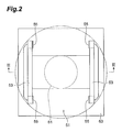
- FIG. 2 is a plan view illustrating a first conveyor unit contained in FIG. 1 .
- FIG. 3 is a sectional view of the first conveyor unit depicted in FIG. 2 along line III-III.
- FIG. 4 is a plan view illustrating a second conveyor unit contained in FIG. 1 .
- FIG. 5 is a sectional view of the second conveyor unit depicted in FIG. 4 along line V-V.
- FIG. 1 is a configuration diagram of conveying system 1 in which a conveyor device 50 according to one embodiment is used.
- the conveying system 1 is a system configured to convey a FOUP (object to be conveyed) 5 conveyed from an inter-level conveying device 10 to any one of transfer positions P 1 to P 4 that are positions for reception and delivery to an overhead traveling vehicle 91 .
- the conveying system 1 of the present embodiment is provided with the transfer positions P 1 to P 4 at four locations.
- the FOUP 5 is a container configured to accommodate wafers and glass substrates, for example, used in a semiconductor manufacturing device or a liquid crystal manufacturing device, for example, and the FOUP 5 is one of standardized containers.
- the inter-level conveying device 10 performs conveyance between different levels with a transfer device (not depicted).
- the overhead traveling vehicle 91 conveys a FOUP 5 between the transfer positions P 1 to P 4 and a load port (not depicted), for example.
- the overhead traveling vehicle 91 can be an overhead hoist transport (OHT) configured to hold and convey a FOUP 5 in a suspended state between the transfer positions P 1 to P 4 and the load port.
- the overhead traveling vehicle 91 travels along a traveling rail 93 provided at a position higher than a floor, e.g., at a ceiling of a clean room.
- the conveying system 1 includes the inter-level conveying device 10 , conveying conveyors 20 , a rotating conveyor 30 , and a conveyor device 50 .
- the conveying conveyors 20 each have a pair of conveyor units 21 configured to support both ends of the bottom of a FOUP 5 in the width direction to convey the FOUP 5 .
- the FOUP 5 is supported at the bottom surface and conveyed by the conveyor units 21 .
- individual conveyance controls are performed by a control device (not depicted), for example.
- the conveying conveyors 20 are disposed between the inter-level conveying device 10 and the rotating conveyor 30 , and also between the rotating conveyor 30 and the conveyor device 50 .
- the rotating conveyor 30 is a unit configured to change the conveying direction of the FOUP 5 and, as depicted in FIG. 1 , has a pair of conveyor units 39 configured to support both ends of the bottom of the FOUP 5 in the width direction to convey the FOUP 5 , a rotating mechanism 33 supporting the pair of conveyor units 39 and rotatably provided, and a main unit 31 supporting the rotating mechanism 33 .
- the rotating conveyor 30 sends out the FOUP 5 conveyed from the upper direction depicted in FIG. 1 toward the conveying conveyor 20 disposed in the right direction depicted in FIG. 1 .
- the conveyor device 50 is a device configured to convey a FOUP 5 between this conveying conveyor 20 and the transfer positions P 1 to P 4 .
- the conveyor device 50 mainly includes first conveyor units 51 , turning units 61 , and second conveyor units 71 . Referring to FIG. 2 to FIG. 4 , the conveyor device 50 will be described in detail below.
- FIG. 2 is a plan view illustrating one of the first conveyor units 51 .
- FIG. 3 is a sectional view of the first conveyor unit 51 depicted in FIG. 2 along line III-III.
- FIG. 4 is a plan view illustrating one of the second conveyor units 71 , which illustrates a state when a FOUP 5 is received and delivered between the first conveyor units 51 and the second conveyor unit 71 .
- FIG. 5 is a sectional view illustrating the second conveyor unit 71 depicted in FIG. 4 along line V-V, which illustrates a state when a FOUP 5 is received and delivered between the first conveyor units 51 and the second conveyor unit 71 .
- each first conveyor unit 51 has a pair of first belts (first supporting-and-conveying units) 53 configured to support both ends of the bottom of a FOUP 5 in the width direction to convey the FOUP 5 .
- the pair of first belts 53 each are a ring-shaped endless belt, and each of the first belts 53 is wound around two rollers 55 and 55 . At least one of the rollers 55 and 55 is driven by a drive unit (not depicted), whereby the respective first belts 53 are rotated in one direction to convey the FOUP 5 supported thereby.
- Each turning unit 61 supports the corresponding first conveyor unit 51 , and turns the first conveyor unit 51 to change the traveling direction of a FOUP 5 .
- the turning unit 61 is rotated by a drive unit (not depicted) to turn the first conveyor unit 51 supported thereby.
- Each turning unit 61 is supported by the upper surface of a main unit 63 .
- the first conveyor unit 51 supported by the turning unit 61 is provided in a manner capable of turning with respect to the main unit 63 .
- each second conveyor unit 71 is provided upon a base portion 85 provided adjacently to the main units 63 of the first conveyor units 51 .
- the second conveyor unit 71 is provided so as to overlap the main units 63 in plan view as depicted in FIG. 4 .
- each second conveyor unit 71 has a pair of second belts (second supporting-and-conveying units) 73 configured to support both ends of the bottom surface of a FOUP 5 in the width direction orthogonal to the conveying direction to convey the FOUP 5 , drive rollers 75 , driven rollers 77 , and conveying rollers (second supporting-and-conveying units) 79 .
- the pair of the second belts 73 each are a ring-shaped endless belt, and each of the second belts 73 is wound around two rollers (the drive roller 75 and the driven roller 77 corresponding thereto).
- the drive roller 75 is driven by a drive unit 81 via a drive shaft (driving-force transmitting unit) 83 .
- Each second belt 73 has a supporting surface (object-supporting surface) 73 A that is substantially parallel to the conveying surface of the FOUP 5 .
- the conveying rollers 79 each are a free roller to which driving force is not transmitted, and constitute part of the conveying surface of the FOUP 5 .
- the pair of the second belts 73 and the drive shaft 83 transmitting driving force to the second belts 73 in the second conveyor unit 71 are provided outside the turning areas A 1 (diagonally hatched portions depicted in FIG. 4 ) of the first conveyor units 51 in plan view, in other words, at positions that do not overlap the turning areas A 1 .
- the first conveyor units 51 and the second conveyor unit 71 are disposed so that the conveying area A 2 (shaded portion depicted in FIG. 4 ) of the FOUP 5 in the second conveyor unit 71 and the turning areas A 1 (diagonally hatched portions depicted in FIG. 4 ) of the first conveyor units 51 overlap each other in plan view as depicted in FIG. 4 .
- the following describes operation of the conveying system 1 when a FOUP 5 is conveyed from the inter-level conveying device 10 to the transfer position P 2 .
- the FOUP 5 in the conveyor device 50 travels along the following route. Specifically, as depicted in FIG. 1 , the FOUP 5 is conveyed via the first conveyor unit 51 A, the second conveyor unit 71 A, the first conveyor unit 51 B, the second conveyor unit 71 B, and the first conveyor unit 51 C in this order.
- the following description is made assuming that the inter-level conveying device 10 side is the upstream side and the transfer position P 2 side is the downstream side.
- the conveying conveyor 20 to which a FOUP 5 has been received and delivered from the inter-level conveying device 10 drives the conveyor units 21 to convey the FOUP 5 downstream.
- the conveying conveyor 20 on the downstream side drives the conveyor units 21 when the FOUP 5 has been conveyed to the conveying conveyor 20 adjacent to the upstream side.
- the rotating conveyor 30 on the downstream side waits for the FOUP 5 to be conveyed thereto with the conveyor units 39 being faced toward the side from which the FOUP 5 is conveyed.
- the rotating conveyor 30 drives the conveyor units 39 .
- the rotating conveyor 30 to which the FOUP 5 has been received and delivered from the conveying conveyor 20 conveys the FOUP 5 to central portions of the conveyor units 39 , and then temporarily stops driving the conveyor units 39 .
- the rotating conveyor 30 drives the rotating mechanism 33 to rotate the conveyor units 39 counterclockwise, so that the conveyor units 39 are faced toward the conveying conveyor 20 adjacent to the downstream side.
- the conveyor units 39 are driven again to send out the FOUP 5 toward the conveying conveyor 20 .
- the conveying conveyor 20 drives the conveyor unit 21 .
- the conveying conveyor 20 to which the FOUP 5 is received and delivered from the rotating conveyor 30 conveys the FOUP 5 toward the conveyor device 50 adjacent to the downstream side.
- the first conveyor unit 51 A of the conveyor device 50 drives the turning unit 61 A so that the first belts 53 are faced toward the side from which the FOUP 5 is conveyed, and waits for the FOUP 5 to be conveyed thereto.
- the first conveyor unit 51 A drives the first belts 53 .
- the first conveyor unit 51 A to which the FOUP 5 is received and delivered from the conveying conveyor 20 conveys the FOUP 5 to the second conveyor unit 71 A disposed adjacently to the downstream side.
- the second conveyor unit 71 A drives the second belts 73 when the FOUP 5 has been conveyed to the first conveyor unit 51 A adjacent to the upstream side.
- the second conveyor unit 71 to which the FOUP 5 has been received and delivered from the first conveyor unit 51 A conveys the FOUP 5 to the first conveyor unit 51 B disposed adjacently to the downstream side.
- the first conveyor unit 51 B on the downstream side drives the turning unit 61 B so that the first belts 53 are faced toward the side from which the FOUP 5 is conveyed, and waits for the FOUP 5 to be conveyed thereto.
- the first conveyor unit 51 B drives the first belts 53 when the FOUP 5 has been conveyed to the second conveyor unit 71 A adjacent to the upstream side.
- the first conveyor unit 51 B to which the FOUP 5 has been received and delivered from the second conveyor unit 71 A conveys the FOUP 5 to central portions of the first belts 53 , and then temporarily stops driving the first belts 53 .
- the first conveyor unit 51 B drives the turning unit 61 B to rotate the first belts 53 counterclockwise, so that the first belts 53 are faced toward the second conveyor unit 71 B adjacent to the downstream side.
- the first belts 53 are driven again to send out the FOUP 5 toward the second conveyor unit 71 B.
- the second belts 73 , the conveying rollers 79 , and the drive shaft 83 of the second conveyor unit 71 B adjacent to the downstream side are disposed outside the conveying area A 1 of the first conveyor units 51 as depicted in FIG. 4 , and thus do not hinder the rotation when the first belts 53 are rotated counterclockwise.
- the first belts 53 when the first belts 53 are faced toward the second conveyor unit 71 B adjacent to the downstream side, as depicted in FIG. 4 , the first belts 53 can be positioned closely to the second belts 73 and the conveying rollers 79 of the second conveyor unit 71 B.
- the FOUP 5 can be stably sent out toward the second conveyor unit 71 B.
- the second conveyor unit 71 B drives the second belts 73 when the FOUP 5 has been conveyed to the first conveyor unit 51 B adjacent to the upstream side.
- the second conveyor unit 71 B to which the FOUP 5 has been received and delivered from the first conveyor unit 51 B conveys the FOUP 5 to the first conveyor unit 51 C disposed adjacently to the downstream side.
- the first conveyor unit 51 C on the downstream side drives the turning unit 61 C so that the first belts 53 are faced toward the side from which the FOUP 5 is conveyed, and waits for the FOUP 5 to be conveyed thereto.
- the first conveyor unit 51 C drives the first belts 53 when the FOUP 5 has been conveyed to the second conveyor unit 71 B adjacent to the upstream side.
- the first conveyor unit 51 C to which the FOUP 5 has been received and delivered from the second conveyor unit 71 B conveys the FOUP 5 to central portions of the first belts 53 , i.e., to the transfer position P 2 , and then temporarily stops driving the first belts 53 .
- the FOUP 5 stopped at the transfer position P 2 is held by the overhead traveling vehicle 91 and is conveyed to a predetermined load port.
- the second conveyor unit 71 does not hinder the turning of the first conveyor unit 51 .
- the second belts 73 in the second conveyor unit 71 are not provided in a manner capable of supporting the whole surface of the FOUP 5 in the conveying area A 2 (shaded portion depicted in FIG.
- each first conveyor unit 51 of the above-described embodiment turns with respect to the main unit 63 provided below the first conveyor unit 51
- each second conveyor unit 71 is provided upon the base portion 85 provided adjacently to the main unit 63 and is disposed so as to overlap the main unit 63 in plan view. Accordingly, because the base portion and the second conveyor unit 71 can be members that are separated from the conveyor device 50 or the first conveyor unit 51 , layout change and maintenance for the conveyor device can be easily performed.
- Each second conveyor unit 71 of the above-described embodiment has the supporting surface 73 A that is substantially parallel to the conveying surface of the FOUP 5 , and thus contact area between the second conveyor unit 71 and the FOUP 5 can be secured, whereby the FOUP 5 can be stably conveyed.
- each second conveyor unit 71 includes the second belts 73 and the conveying rollers 79 , but the present invention is not limited to this.
- the second belts 73 may be configured to convey the FOUP 5 instead.
- the present invention is not limited to this.
- one belt capable of supporting the entire bottom surface of the FOUP (object to be conveyed) 5 may be provided instead.
- the conveyor device 50 of the above-described embodiment an example has been described in which three first conveyor units 51 with turning units 61 and two second conveyor units 71 are disposed in the upper-and-lower direction in FIG. 1 , and a combination of these units is disposed in two rows in the left-and-right direction, and also a second conveyor unit 71 is disposed between these combinations, but the present invention is not limited to this.
- the conveyor device 50 is only required to include at least one first conveyor unit 51 , a turning unit 61 configured to turn this first conveyor unit 51 , and at least one second conveyor unit 71 disposed adjacently to the first conveyor unit.
- 1 . . . conveying system 5 . . . FOUP (object to be conveyed), 10 . . . inter-level conveying device, 20 . . . conveying conveyor, 21 . . . conveyor unit, 30 . . . rotating conveyor, 31 . . . main unit, 33 . . . rotating mechanism, 39 . . . conveyor unit, 50 . . . conveyor device, 51 . . . first conveyor unit, 53 . . . first belt (first supporting-and-conveying unit), 55 . . . roller, 61 . . . turning unit, 63 . . . main unit, 71 . . . second conveyor unit, 73 .
- second belt (second supporting-and-conveying unit), 73 A . . . supporting surface (object-supporting surface), 75 . . . drive roller, 77 . . . driven roller, 79 . . . conveying roller (second supporting-and-conveying unit), 81 . . . drive unit, 83 . . . drive shaft (driving-force transmitting unit), 85 . . . base portion, 91 . . . overhead traveling vehicle, 93 . . . traveling rail, A 1 . . . turning area, A 2 . . . conveying area, P 1 to P 4 . . . transfer position
Landscapes
- Engineering & Computer Science (AREA)
- Physics & Mathematics (AREA)
- Mechanical Engineering (AREA)
- Manufacturing & Machinery (AREA)
- General Physics & Mathematics (AREA)
- Power Engineering (AREA)
- Computer Hardware Design (AREA)
- Microelectronics & Electronic Packaging (AREA)
- Condensed Matter Physics & Semiconductors (AREA)
- Nonlinear Science (AREA)
- Container, Conveyance, Adherence, Positioning, Of Wafer (AREA)
- Chemical & Material Sciences (AREA)
- Crystallography & Structural Chemistry (AREA)
- Optics & Photonics (AREA)
- Intermediate Stations On Conveyors (AREA)
- Rollers For Roller Conveyors For Transfer (AREA)
- Warehouses Or Storage Devices (AREA)
- Relays Between Conveyors (AREA)
Applications Claiming Priority (3)
| Application Number | Priority Date | Filing Date | Title |
|---|---|---|---|
| JP2013-223475 | 2013-10-28 | ||
| JP2013223475 | 2013-10-28 | ||
| PCT/JP2014/075930 WO2015064268A1 (ja) | 2013-10-28 | 2014-09-29 | コンベヤ装置 |
Publications (2)
| Publication Number | Publication Date |
|---|---|
| US20160236872A1 US20160236872A1 (en) | 2016-08-18 |
| US9670002B2 true US9670002B2 (en) | 2017-06-06 |
Family
ID=53003881
Family Applications (1)
| Application Number | Title | Priority Date | Filing Date |
|---|---|---|---|
| US15/030,343 Expired - Fee Related US9670002B2 (en) | 2013-10-28 | 2014-09-29 | Conveyor device |
Country Status (8)
| Country | Link |
|---|---|
| US (1) | US9670002B2 (de) |
| EP (1) | EP3064455A4 (de) |
| JP (1) | JP6288103B2 (de) |
| KR (1) | KR101869813B1 (de) |
| CN (1) | CN105658551B (de) |
| SG (1) | SG11201603110PA (de) |
| TW (1) | TWI567009B (de) |
| WO (1) | WO2015064268A1 (de) |
Cited By (2)
| Publication number | Priority date | Publication date | Assignee | Title |
|---|---|---|---|---|
| US20180229937A1 (en) * | 2017-02-10 | 2018-08-16 | Itoh Denki Co., Ltd. | Conveying device and conveyor unit |
| US10947053B2 (en) | 2016-12-19 | 2021-03-16 | Carl Zeiss Vision International Gmbh | Production system for spectacle lenses |
Families Citing this family (6)
| Publication number | Priority date | Publication date | Assignee | Title |
|---|---|---|---|---|
| HUE051238T2 (hu) * | 2016-12-19 | 2021-03-01 | Zeiss Carl Vision Int Gmbh | Továbbító berendezés egy szállítótartály számára |
| DE102016225485B4 (de) | 2016-12-19 | 2022-08-25 | Carl Zeiss Vision International Gmbh | Sicheres Fördersystem |
| CH715069A1 (de) | 2018-06-05 | 2019-12-13 | Ruggli Projects Ag | Fördereinrichtung und Verfahren zum Fördern von Tampon-Applikatoren. |
| EP3875405A4 (de) * | 2018-11-02 | 2022-08-10 | Murata Machinery, Ltd. | Fördersystem |
| JP7473201B2 (ja) | 2020-05-18 | 2024-04-23 | アイカム株式会社 | 飲食物の搬送システム |
| EP3922205A1 (de) * | 2020-06-12 | 2021-12-15 | Gibotech A/S | System zum anordnen von behältern und behälterdeckeln auf einem gestell in einer sterilen verarbeitungsabteiliung |
Citations (19)
| Publication number | Priority date | Publication date | Assignee | Title |
|---|---|---|---|---|
| JPS5841725A (ja) | 1981-08-26 | 1983-03-11 | シエル・インタ−ナシヨナル・リサ−チ・マ−トスハツペイ・ベ−・ヴエ− | 酸触媒抽出物からの五価バナジウム化合物の回収方法 |
| US4457419A (en) * | 1981-04-03 | 1984-07-03 | Dainippon Screen Mgf., Co., Ltd. | Conveying/positioning apparatus for sheet material |
| JPH03281186A (ja) | 1990-03-28 | 1991-12-11 | Tokyo Autom Mach Works Ltd | つなぎ込みロボット |
| US5141095A (en) * | 1990-04-28 | 1992-08-25 | Palitex Project Company Gmbh | Package transport device |
| JPH062527B2 (ja) | 1984-04-27 | 1994-01-12 | 株式会社東芝 | クリーンルーム用搬送システム |
| US5341911A (en) * | 1992-06-23 | 1994-08-30 | G. D. Societa' Per Azioni | Method and device for feeding a succession of reels to a pickup station |
| US6223886B1 (en) * | 1998-06-24 | 2001-05-01 | Asyst Technologies, Inc. | Integrated roller transport pod and asynchronous conveyor |
| US6308818B1 (en) * | 1999-08-02 | 2001-10-30 | Asyst Technologies, Inc. | Transport system with integrated transport carrier and directors |
| US6907983B2 (en) * | 2001-11-22 | 2005-06-21 | Knapp Logistic Automation Gmbh | Conveying device for conveying stock on pallets or the like with change of direction |
| US20070186799A1 (en) | 2006-02-14 | 2007-08-16 | Asyst Shinko, Inc. | Direction change device |
| TWM324648U (en) | 2007-06-08 | 2008-01-01 | Contrel Technology Co Ltd | Air-levitation conveyor capable of changing feeding direction of board |
| JP4178835B2 (ja) | 2002-05-28 | 2008-11-12 | 株式会社ダイフク | 分岐設備 |
| US7600629B2 (en) * | 2005-07-20 | 2009-10-13 | Bosch Rexroth Ag | Conveyor system |
| US8061500B2 (en) * | 2007-10-24 | 2011-11-22 | Applied Materials Italia S.R.L. | Alignment device and method to align plates for electronic circuits |
| US8312981B2 (en) * | 2008-02-21 | 2012-11-20 | Grenzebach Maschinenbau Gmbh | Method and device for conveying and rotating impact-sensitive panels in ultra clean rooms |
| US8327997B2 (en) * | 2010-07-21 | 2012-12-11 | Otsuka Electronics Co., Ltd. | Transferred object rotating device |
| US8550228B1 (en) * | 2013-03-01 | 2013-10-08 | Anko Food Machine Co., Ltd. | Direction change device for conveyance of dough |
| US8776983B2 (en) * | 2012-06-26 | 2014-07-15 | Shenzhen China Star Optoelectronics Technology Co., Ltd | Turntable device for substrate and substrate transporting system |
| US9221622B2 (en) * | 2014-01-24 | 2015-12-29 | Axium Inc. | Product orientor |
Family Cites Families (9)
| Publication number | Priority date | Publication date | Assignee | Title |
|---|---|---|---|---|
| BE793146A (fr) * | 1972-02-03 | 1973-04-16 | Windmoeller & Hoelscher | Section de transport destinee a transporter des paquets de pieces pour la fabrication de sacs |
| JPS5841725U (ja) * | 1981-09-14 | 1983-03-19 | 松下電工株式会社 | 搬送装置 |
| JPH062527A (ja) | 1992-06-16 | 1994-01-11 | Toyota Motor Corp | 内燃機関の排気浄化装置 |
| JPH09255144A (ja) * | 1996-03-21 | 1997-09-30 | Komatsu Giken Kk | 基板旋回装置 |
| US6572321B1 (en) * | 2000-10-05 | 2003-06-03 | Applied Materials, Inc. | Loader conveyor for substrate processing system |
| JP2003285924A (ja) * | 2002-03-28 | 2003-10-07 | Nec Machinery Corp | ワーク切断分配システム |
| JP2005212948A (ja) * | 2004-01-28 | 2005-08-11 | Shinmei Ind Co Ltd | コンベヤ装置 |
| JP2009280333A (ja) * | 2008-05-21 | 2009-12-03 | Fdk Engineering:Kk | ローラコンベア装置 |
| JP5513137B2 (ja) * | 2010-01-05 | 2014-06-04 | トーヨーカネツソリューションズ株式会社 | アキュムレーションコンベヤ |
-
2014
- 2014-09-29 JP JP2015544879A patent/JP6288103B2/ja not_active Expired - Fee Related
- 2014-09-29 KR KR1020167011313A patent/KR101869813B1/ko active IP Right Grant
- 2014-09-29 US US15/030,343 patent/US9670002B2/en not_active Expired - Fee Related
- 2014-09-29 CN CN201480057228.2A patent/CN105658551B/zh not_active Expired - Fee Related
- 2014-09-29 EP EP14857155.7A patent/EP3064455A4/de not_active Withdrawn
- 2014-09-29 SG SG11201603110PA patent/SG11201603110PA/en unknown
- 2014-09-29 WO PCT/JP2014/075930 patent/WO2015064268A1/ja active Application Filing
- 2014-10-24 TW TW103136772A patent/TWI567009B/zh not_active IP Right Cessation
Patent Citations (19)
| Publication number | Priority date | Publication date | Assignee | Title |
|---|---|---|---|---|
| US4457419A (en) * | 1981-04-03 | 1984-07-03 | Dainippon Screen Mgf., Co., Ltd. | Conveying/positioning apparatus for sheet material |
| JPS5841725A (ja) | 1981-08-26 | 1983-03-11 | シエル・インタ−ナシヨナル・リサ−チ・マ−トスハツペイ・ベ−・ヴエ− | 酸触媒抽出物からの五価バナジウム化合物の回収方法 |
| JPH062527B2 (ja) | 1984-04-27 | 1994-01-12 | 株式会社東芝 | クリーンルーム用搬送システム |
| JPH03281186A (ja) | 1990-03-28 | 1991-12-11 | Tokyo Autom Mach Works Ltd | つなぎ込みロボット |
| US5141095A (en) * | 1990-04-28 | 1992-08-25 | Palitex Project Company Gmbh | Package transport device |
| US5341911A (en) * | 1992-06-23 | 1994-08-30 | G. D. Societa' Per Azioni | Method and device for feeding a succession of reels to a pickup station |
| US6223886B1 (en) * | 1998-06-24 | 2001-05-01 | Asyst Technologies, Inc. | Integrated roller transport pod and asynchronous conveyor |
| US6308818B1 (en) * | 1999-08-02 | 2001-10-30 | Asyst Technologies, Inc. | Transport system with integrated transport carrier and directors |
| US6907983B2 (en) * | 2001-11-22 | 2005-06-21 | Knapp Logistic Automation Gmbh | Conveying device for conveying stock on pallets or the like with change of direction |
| JP4178835B2 (ja) | 2002-05-28 | 2008-11-12 | 株式会社ダイフク | 分岐設備 |
| US7600629B2 (en) * | 2005-07-20 | 2009-10-13 | Bosch Rexroth Ag | Conveyor system |
| US20070186799A1 (en) | 2006-02-14 | 2007-08-16 | Asyst Shinko, Inc. | Direction change device |
| TWM324648U (en) | 2007-06-08 | 2008-01-01 | Contrel Technology Co Ltd | Air-levitation conveyor capable of changing feeding direction of board |
| US8061500B2 (en) * | 2007-10-24 | 2011-11-22 | Applied Materials Italia S.R.L. | Alignment device and method to align plates for electronic circuits |
| US8312981B2 (en) * | 2008-02-21 | 2012-11-20 | Grenzebach Maschinenbau Gmbh | Method and device for conveying and rotating impact-sensitive panels in ultra clean rooms |
| US8327997B2 (en) * | 2010-07-21 | 2012-12-11 | Otsuka Electronics Co., Ltd. | Transferred object rotating device |
| US8776983B2 (en) * | 2012-06-26 | 2014-07-15 | Shenzhen China Star Optoelectronics Technology Co., Ltd | Turntable device for substrate and substrate transporting system |
| US8550228B1 (en) * | 2013-03-01 | 2013-10-08 | Anko Food Machine Co., Ltd. | Direction change device for conveyance of dough |
| US9221622B2 (en) * | 2014-01-24 | 2015-12-29 | Axium Inc. | Product orientor |
Non-Patent Citations (4)
| Title |
|---|
| English language translation of International Search Report dated Dec. 22, 2014 issued in corresponding PCT application PCT/JP2014/075930 cites the foreign patent documents listed above. |
| International Preliminary Report on Patentability dated May 12, 2016, issued in corresponding International Application No. PCT/JP2014/075930. |
| Office Action dated Nov. 30, 2016 issued in corresponding Chinese Patent Application No. 201480057228.2 cites the United States patent document above. |
| Written Opinion of the International Searching Authority dated Dec. 22, 2014, issued in corresponding International Application No. PCT/JP2014/075930. |
Cited By (3)
| Publication number | Priority date | Publication date | Assignee | Title |
|---|---|---|---|---|
| US10947053B2 (en) | 2016-12-19 | 2021-03-16 | Carl Zeiss Vision International Gmbh | Production system for spectacle lenses |
| US20180229937A1 (en) * | 2017-02-10 | 2018-08-16 | Itoh Denki Co., Ltd. | Conveying device and conveyor unit |
| US10464756B2 (en) * | 2017-02-10 | 2019-11-05 | Itoh Denki Co., Ltd. | Conveying device and conveyor unit |
Also Published As
| Publication number | Publication date |
|---|---|
| KR101869813B1 (ko) | 2018-06-21 |
| EP3064455A4 (de) | 2017-06-21 |
| TW201529451A (zh) | 2015-08-01 |
| CN105658551B (zh) | 2018-10-26 |
| SG11201603110PA (en) | 2016-05-30 |
| CN105658551A (zh) | 2016-06-08 |
| US20160236872A1 (en) | 2016-08-18 |
| WO2015064268A1 (ja) | 2015-05-07 |
| KR20160064199A (ko) | 2016-06-07 |
| JP6288103B2 (ja) | 2018-03-07 |
| EP3064455A1 (de) | 2016-09-07 |
| TWI567009B (zh) | 2017-01-21 |
| JPWO2015064268A1 (ja) | 2017-03-09 |
Similar Documents
| Publication | Publication Date | Title |
|---|---|---|
| US9670002B2 (en) | Conveyor device | |
| JP4615015B2 (ja) | コンテナ搬送システム | |
| US10196214B2 (en) | Conveyor car system | |
| CN112912321B (zh) | 顶棚悬吊搁板 | |
| JP4858673B2 (ja) | 懸垂式昇降搬送台車の搬送システム | |
| CN102673964A (zh) | 物品运送设备 | |
| WO2020090323A1 (ja) | コンベヤシステム | |
| TWI763871B (zh) | 搬運系統及搬運方法 | |
| TWI760422B (zh) | 物品搬送車 | |
| JP5401842B2 (ja) | 搬送システム | |
| JP4674344B2 (ja) | 搬送物昇降装置 | |
| WO2017043234A1 (ja) | 搬送システム及び搬送方法 | |
| JP5344366B2 (ja) | 搬送システム | |
| KR101561226B1 (ko) | 이송대차 시스템 | |
| JP6729466B2 (ja) | 物品搬送設備 | |
| KR101504145B1 (ko) | 반송시스템 및 그 대차장치 | |
| KR200259585Y1 (ko) | 디버터 | |
| TW202227345A (zh) | 搬運系統 | |
| JP2020066495A (ja) | コンベヤシステム | |
| TW202233497A (zh) | 搬運系統 | |
| JP2006135030A (ja) | 基板搬送設備及び天井搬送装置 | |
| JPH1059520A (ja) | 循環チェーンコンベア装置 | |
| JP2007005503A (ja) | 容器移載装置及び移載方法 |
Legal Events
| Date | Code | Title | Description |
|---|---|---|---|
| AS | Assignment |
Owner name: MURATA MACHINERY, LTD., JAPAN Free format text: ASSIGNMENT OF ASSIGNORS INTEREST;ASSIGNOR:KATO, SUSUMO;REEL/FRAME:038309/0462 Effective date: 20160411 |
|
| STCF | Information on status: patent grant |
Free format text: PATENTED CASE |
|
| LAPS | Lapse for failure to pay maintenance fees |
Free format text: PATENT EXPIRED FOR FAILURE TO PAY MAINTENANCE FEES (ORIGINAL EVENT CODE: EXP.); ENTITY STATUS OF PATENT OWNER: LARGE ENTITY |
|
| FEPP | Fee payment procedure |
Free format text: MAINTENANCE FEE REMINDER MAILED (ORIGINAL EVENT CODE: REM.); ENTITY STATUS OF PATENT OWNER: LARGE ENTITY |
|
| STCH | Information on status: patent discontinuation |
Free format text: PATENT EXPIRED DUE TO NONPAYMENT OF MAINTENANCE FEES UNDER 37 CFR 1.362 |
|
| FP | Lapsed due to failure to pay maintenance fee |
Effective date: 20210606 |