US9643796B2 - Device and method of arraying articles by using robot, and article transfer system - Google Patents
Device and method of arraying articles by using robot, and article transfer system Download PDFInfo
- Publication number
- US9643796B2 US9643796B2 US14/632,166 US201514632166A US9643796B2 US 9643796 B2 US9643796 B2 US 9643796B2 US 201514632166 A US201514632166 A US 201514632166A US 9643796 B2 US9643796 B2 US 9643796B2
- Authority
- US
- United States
- Prior art keywords
- article
- arrangement
- arraying
- articles
- robot
- Prior art date
- Legal status (The legal status is an assumption and is not a legal conclusion. Google has not performed a legal analysis and makes no representation as to the accuracy of the status listed.)
- Active, expires
Links
Images


Classifications
-
- B—PERFORMING OPERATIONS; TRANSPORTING
- B65—CONVEYING; PACKING; STORING; HANDLING THIN OR FILAMENTARY MATERIAL
- B65G—TRANSPORT OR STORAGE DEVICES, e.g. CONVEYORS FOR LOADING OR TIPPING, SHOP CONVEYOR SYSTEMS OR PNEUMATIC TUBE CONVEYORS
- B65G47/00—Article or material-handling devices associated with conveyors; Methods employing such devices
- B65G47/74—Feeding, transfer, or discharging devices of particular kinds or types
- B65G47/90—Devices for picking-up and depositing articles or materials
- B65G47/905—Control arrangements
-
- B—PERFORMING OPERATIONS; TRANSPORTING
- B25—HAND TOOLS; PORTABLE POWER-DRIVEN TOOLS; MANIPULATORS
- B25J—MANIPULATORS; CHAMBERS PROVIDED WITH MANIPULATION DEVICES
- B25J9/00—Programme-controlled manipulators
- B25J9/16—Programme controls
- B25J9/1694—Programme controls characterised by use of sensors other than normal servo-feedback from position, speed or acceleration sensors, perception control, multi-sensor controlled systems, sensor fusion
- B25J9/1697—Vision controlled systems
-
- G—PHYSICS
- G05—CONTROLLING; REGULATING
- G05B—CONTROL OR REGULATING SYSTEMS IN GENERAL; FUNCTIONAL ELEMENTS OF SUCH SYSTEMS; MONITORING OR TESTING ARRANGEMENTS FOR SUCH SYSTEMS OR ELEMENTS
- G05B19/00—Programme-control systems
- G05B19/02—Programme-control systems electric
- G05B19/418—Total factory control, i.e. centrally controlling a plurality of machines, e.g. direct or distributed numerical control [DNC], flexible manufacturing systems [FMS], integrated manufacturing systems [IMS], computer integrated manufacturing [CIM]
- G05B19/41815—Total factory control, i.e. centrally controlling a plurality of machines, e.g. direct or distributed numerical control [DNC], flexible manufacturing systems [FMS], integrated manufacturing systems [IMS], computer integrated manufacturing [CIM] characterised by the cooperation between machine tools, manipulators and conveyor or other workpiece supply system, workcell
- G05B19/4182—Total factory control, i.e. centrally controlling a plurality of machines, e.g. direct or distributed numerical control [DNC], flexible manufacturing systems [FMS], integrated manufacturing systems [IMS], computer integrated manufacturing [CIM] characterised by the cooperation between machine tools, manipulators and conveyor or other workpiece supply system, workcell manipulators and conveyor only
-
- Y—GENERAL TAGGING OF NEW TECHNOLOGICAL DEVELOPMENTS; GENERAL TAGGING OF CROSS-SECTIONAL TECHNOLOGIES SPANNING OVER SEVERAL SECTIONS OF THE IPC; TECHNICAL SUBJECTS COVERED BY FORMER USPC CROSS-REFERENCE ART COLLECTIONS [XRACs] AND DIGESTS
- Y02—TECHNOLOGIES OR APPLICATIONS FOR MITIGATION OR ADAPTATION AGAINST CLIMATE CHANGE
- Y02P—CLIMATE CHANGE MITIGATION TECHNOLOGIES IN THE PRODUCTION OR PROCESSING OF GOODS
- Y02P90/00—Enabling technologies with a potential contribution to greenhouse gas [GHG] emissions mitigation
- Y02P90/02—Total factory control, e.g. smart factories, flexible manufacturing systems [FMS] or integrated manufacturing systems [IMS]
-
- Y02P90/083—
Definitions
- the present invention relates to a device and a method of arraying articles by using a robot.
- the present invention also relates to an article transfer system that includes an article arraying device.
- JP2013-000860A discloses a picking system in which a plurality of robots pick up a plurality of respective workpieces conveyed by a conveyor in a random arrangement.
- this picking system an image area of a camera is divided into a plurality of areas and a transfer motion for a workpiece in each of the areas is executed by a robot associated in advance with the corresponding area.
- Japanese Unexamined Patent Publication No. 2013-000861 JP2013-000861A discloses another picking system in which a plurality of robots pick up a plurality of respective workpieces conveyed by a conveyor in a random arrangement.
- directions of individual workpieces in an image captured by a camera are determined to belong to which of a plurality of predetermined angle ranges and a transfer motion for each workpiece is executed by a robot associated in advance with the corresponding angle range.
- JP5288908B discloses an article arraying system for arraying a plurality of articles supplied in a random arrangement with a plurality of robots so as to rearrange the articles to a regular arrangement in which articles have the same orientation and mutually corresponding surfaces thereof face in the same direction.
- JP5288908B recites a robot gripper that has a characteristic configuration applicable to the article arraying system.
- a robot picks up a plurality of articles placed in a random arrangement and transfers the articles to another place, it is desired to improve working efficiency in transferring the articles to another place so as to maintain a regular arrangement in which the articles are juxtaposed to each other.
- a robot arrays a plurality of articles so as to rearrange the articles from a random arrangement to a regular arrangement, it is desired to improve working efficiency in arraying the articles and to allow a general-purpose robot to be used.
- One aspect of the present invention provides an article arraying device configured to array a plurality of articles so as to rearrange the articles from a random arrangement to a regular arrangement, comprising a robot configured to hold an article; a vision sensor configured to obtain position information of each of a plurality of articles placed in a random arrangement; an arrangement pattern generating section configured to generate an arrangement pattern with use of the position information, the arrangement pattern including a plurality of pattern elements in a predetermined regular arrangement, each pattern element representing a position of an article, in such a manner that a first pattern element that is any one of the plurality of pattern elements coincides with a position of a reference article that is any one of the plurality of articles placed in the random arrangement; a picking motion generating section configured to generate a picking motion of the robot with use of the position information, the robot being configured to pick up, by the picking motion, an article other than the reference article; an arraying motion generating section configured to generate an arraying motion of the robot, the robot being configured to place, by the arraying motion, the article picked up by
- the arrangement pattern is generated on site by considering any one of the articles placed in the random arrangement as the reference article, and the robot operates to place the other article in a position juxtaposed to the reference article in accordance with the arrangement pattern, without moving the reference article, and thereby it is possible to array the articles in the regular arrangement. Therefore, regarding an operation for rearranging a single article from the random arrangement to the regular arrangement as a unit operation, it is possible to array the articles, the number of which is one more than the number of unit operations, and thereby to improve the efficiency in the arraying operation as an assemblage of unit operations. Also, it is possible to use a general-purpose robot, as long as it can perform the picking motion and the arraying motion while holding the article. An article arraying method according to another aspect provides the same effect.
- the article arraying device may further comprise an interference judging section configured to predictively judge as to whether an interference is caused between an article capable of being placed on a second pattern element in the arrangement pattern, different from the first pattern element, and another article including the reference article, with use of shape information of each of the plurality of articles together with the position information.
- the picking motion generating section may be configured to generate the picking motion in consideration of a judgment of the interference judging section; and the arraying motion generating section may be configured to generate the arraying motion in consideration of a judgment of the interference judging section.
- the robot executes the picking motion and the arraying motion in the unit operation, in which the interference is efficiently avoidable through judging whether the interference is caused between the articles.
- the robot executes the picking motion and the arraying motion in the unit operation, in which the interference is efficiently avoidable through judging whether the interference is caused between the articles.
- Another aspect of the present invention provides an article transfer system, comprising the aforementioned article arraying device; a conveying device configured to convey a plurality of articles in a regular arrangement in which the articles are juxtaposed to each other; and a transfer robot configured to collectively hold a plurality of articles arrayed in the regular arrangement by the article arraying device and to transfer the articles to the conveying device.
- the transfer robot can collectively hold the predetermined number of articles arrayed in the regular arrangement by the article arraying device and transfer them to the conveying device, with the regular arrangement maintained.
- the transfer robot does not need to have a function of arraying the articles, and thereby it is possible to improve efficiency of the transferring operation.
- a further aspect of the present invention provides an article arraying method for making a robot array a plurality of articles so as to rearrange the articles from a random arrangement to a regular arrangement, comprising obtaining position information of each of a plurality of articles placed in a random arrangement; generating an arrangement pattern with use of the position information, the arrangement pattern including a plurality of pattern elements in a predetermined regular arrangement, each pattern element representing a position of an article, in such a manner that a first pattern element that is any one of the plurality of pattern elements coincides with a position of a reference article that is any one of the plurality of articles placed in the random arrangement; generating a picking motion of the robot with use of the position information, the robot being configured to pick up, by the picking motion, an article other than the reference article; generating an arraying motion of the robot, the robot being configured to place, by the arraying motion, the article picked up by the picking motion in a position juxtaposed to the reference article in accordance with the arrangement pattern; and controlling the picking motion and the arraying motion of
- FIG. 1 is a functional block diagram illustrating a configuration of an article arraying device according to one aspect
- FIG. 2 is a schematic illustration of one example of an arrangement pattern
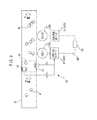
- FIG. 3 is an illustration of an example of articles arrayed in accordance with an arrangement pattern
- FIG. 4 is a table depicting an example of an arrangement form defining a pattern element
- FIG. 5A depicts another example of an arrangement form
- FIG. 5B depicts another example of an arrangement pattern
- FIG. 5C depicts articles arrayed in accordance with the other example of an arrangement pattern
- FIG. 6A depicts a further example of an arrangement form
- FIG. 6B depicts articles arrayed in accordance with a further example of an arrangement pattern
- FIG. 7 is an illustration of an example of an article
- FIGS. 8A and 8B are illustrations of other examples of articles arrayed in accordance with an arrangement pattern
- FIG. 9 is a schematic illustration of one embodiment of an article arraying device
- FIG. 10 is a block diagram illustrating an example of a hardware configuration of a control device
- FIG. 11 is a block diagram illustrating another example of a hardware configuration of a control device
- FIG. 12 is a functional block diagram of a control device in the embodiment of FIG. 9 ;
- FIG. 13 is a schematic illustration depicting a process for generating an arrangement pattern in the embodiment of FIG. 9 ;
- FIG. 14 is a schematic illustration depicting a process for generating an arrangement pattern in the embodiment of FIG. 9 ;
- FIG. 15 is a schematic illustration depicting a process for generating an arrangement pattern in the embodiment of FIG. 9 ;
- FIG. 16 is a schematic illustration depicting a process for generating an arrangement pattern in the embodiment of FIG. 9 ;
- FIG. 17 is a schematic illustration depicting a process for generating an arrangement pattern in the embodiment of FIG. 9 ;
- FIG. 18 is a schematic illustration depicting a process for generating an arrangement pattern in the embodiment of FIG. 9 ;
- FIG. 19 is a schematic illustration depicting a process for generating an arrangement pattern in the embodiment of FIG. 9 ;
- FIG. 20 is a schematic illustration depicting a process for generating an arrangement pattern in the embodiment of FIG. 9 ;
- FIG. 21 is a flowchart of an arrangement pattern generating process executed in a control device
- FIG. 22 is a flowchart of an arrangement pattern generating process executed in a control device
- FIG. 23 is a flowchart of an arrangement pattern generating process executed in a control device
- FIG. 24 is an illustration of an embodiment of an article transfer system according to another aspect
- FIG. 25 is a functional block diagram of a control device in the embodiment of FIG. 24 ;
- FIG. 26 is a flowchart of an article transfer process executed in a control device
- FIG. 27 is a functional block diagram illustrating a configuration of an article transfer system according to a further aspect
- FIG. 28 is a functional block diagram illustrating a configuration of an article arraying device according to yet another aspect
- FIG. 29A depicts a yet further example of an arrangement form
- FIG. 29B a top plan view of articles arrayed in accordance with a yet further example of an arrangement pattern.
- FIG. 29C a side view of the articles of FIG. 29B .
- FIG. 1 is a functional block diagram illustrating a configuration of an article arraying device 10 according to one embodiment of the present invention.
- the article arraying device 10 is configured to array a plurality of articles M by a robot 12 , so as to rearrange the articles from a random arrangement to a regular arrangement.
- the article arraying device 10 includes a robot 12 configured to hold an article M; a vision sensor 14 configured to obtain position information Dp of each of a plurality of articles M placed in a random arrangement; an arrangement pattern generating section 16 configured to generate, in a virtual manner, an arrangement pattern P with use of the position information Dp, the arrangement pattern P including a plurality of pattern elements in a predetermined regular arrangement, each pattern element representing a position of an article M, in such a manner that a first pattern element that is any one of the plurality of pattern elements coincides with a position of a reference article Ma that is any one of the plurality of articles M placed in the random arrangement; an interference judging section 18 configured to predictively judge as to whether an interference is caused between an article Mb capable of being placed on a second pattern element in the arrangement pattern, different from the first pattern element, and another article M including the reference article Ma, with use of shape information Ds of each of the plurality of articles together with the position information Dp; a picking motion generating section 20 configured to generate a picking motion of
- the article M may be variously shaped and dimensioned.
- the articles M having various shapes and sizes, or the articles M having the same shape and size, may be placed in the random arrangement.
- the “random arrangement” means an arrangement where the articles M are randomly arranged and not intended to be arranged in a certain form. More specifically, the random arrangement means that, in a two-dimensional extent (e.g., in an image obtained by the vision sensor 14 ) defined when viewing the plurality of articles M from directly above, the respective articles M take various positions and orientations.
- the “regular arrangement” achieved by the article arraying device 10 means an arrangement wherein the plurality of articles M are arranged under a predetermined rule, such as in a linear array, a curved array, a zigzag array, an annular array, etc., in the two-dimensional extent.
- the orientations (or the directions) of the respective articles M may be identical to or different from each other, and the distances between the adjacent pairs of articles M may be identical to or different from each other.
- the robot 12 may include a mechanical section appropriately selected from various known mechanical sections, such as an articulated type, a gantry type, a parallel link type, etc. As described later, the robot 12 may not have a configuration dedicated for an article arraying operation performed by the article arraying device 10 , but the robot 12 and an end effector, such as a gripper, may have a versatile configuration.
- the vision sensor 14 includes an image capturing section such as a CCD camera, and an image processing section such as a dedicated image processor or one function of a control device described later.
- the image capturing section captures an image of the plurality of articles M placed in the random arrangement in a viewing field of the image capturing section from directly above (i.e., in a plan view), and the image processing section performs appropriate image processing on the captured image data, so that the vision sensor 14 detects the existence of the article M and obtains information of position (coordinate value) and orientation (rotational angle) of each article M in a predetermined two-dimensional camera coordinate system.
- the position information Dp obtained by the vision sensor 14 includes the information of the position and the orientation of the article M.
- the position information Dp may not include the information of the orientation of the article M, in a configuration where, for example, a suction gripper that does not limit a holing position of the article M is attached to the robot 12 , and the plurality of articles M arrayed in the regular arrangement take various orientations.
- the vision sensor 14 may further obtain information of a two-dimensional outer shape of each article M (i.e., shape information Ds) from the image data.
- shape information Ds obtained by the vision sensor 14 , may be displayed as images on a monitor (not shown).
- the arrangement pattern generating section 16 , the interference judging section 18 , the picking motion generating section 20 , the arraying motion generating section 22 , and the robot controlling section 24 are configured respectively as functional components of a control device described later.
- the functions of the respective sections will be described in more detail in later-described embodiments.
- FIG. 2 schematically illustrates one example of the arrangement pattern P generated by the arrangement pattern generating section 16 .
- the arrangement pattern P of the illustrated example includes a plurality of (three) pattern elements P 1 , P 2 and P 3 , each representing a position of the article M, in a predetermined regular arrangement (in the drawing, linearly arrayed in a lateral direction).
- Each of the pattern elements P 1 , P 2 and P 3 is illustrated by a “+” mark for the sake of easier understanding, but does not need to have any shape.
- the arrangement pattern P may include two, four or more pattern elements, and may include pattern elements arrayed according to other rules, such as a curved array, a zigzag array, or an annular array.
- the arrangement pattern generating section 16 is able to generate the arrangement pattern P based on an arrangement form, the arrangement form being configured to define each of the plurality of pattern elements by a coordinate value in a predetermined pattern coordinate system.
- an arrangement form that defines the pattern elements P 1 , P 2 and P 3 by a coordinate values (X1, Y1), (X2, Y1) and (X3, Y1), respectively, is provided in a pattern coordinate system 26 set at a certain position in the camera coordinate system.
- the arrangement pattern generating section 16 virtually generates the arrangement pattern P, including the linearly-arrayed pattern elements P 1 , P 2 and P 3 , on the site where the plurality of articles M are to be arrayed in a regular arrangement.
- the robot 12 operates in accordance with the generated arrangement pattern P so as to rearrange the plurality of articles M from the random arrangement to the regular arrangement in which the articles are linearly arrayed.
- any one of the plurality of articles M placed in the random arrangement is set as the reference article Ma ( FIG. 1 ), and the robot 12 operates so as not to move the reference article Ma but to place the other article Mb ( FIG. 1 ) in a position juxtaposed to the reference article Ma.
- FIG. 3 illustrates an example of the articles M arrayed in the regular arrangement in accordance with the arrangement pattern P in FIG. 2 .
- three articles M having the same rectangular two-dimensional shape are arranged with the geometrical centers thereof being positioned at three pattern elements P 1 , P 2 and P 3 of the arrangement pattern P.
- the reference article Ma is first selected from the plurality of articles M placed in the random arrangement, and a first pattern element (the leftmost pattern element P 1 , in the drawing) that is one of the plurality of pattern elements defined by the arrangement form ( FIG.
- the robot 12 places the other articles Mb so as to coincide with the second pattern elements (P 2 and P 3 ), in accordance with the arrangement pattern P. In this manner, the three articles M are arrayed in the regular arrangement in accordance with the arrangement pattern P.
- the articles M are arrayed by positioning or aligning the geometrical center of the two-dimensional shape of each of the articles M (Ma, Mb) at each of the pattern elements P 1 , P 2 and P 3 .
- the articles M may be arrayed by positioning or aligning any other portion than the geometrical center (e.g., one apex of the rectangle) at the pattern element, provided that the portion of one article M corresponds to that of the other article M in view of the shape of the articles M.
- an operator may set a portion of the article M, which is to be positioned at a pattern element, and provide it to the arraying motion generating section 22 (i.e., input the set portion to the control device described later).
- each of the pattern elements P 1 , P 2 and P 3 of the arrangement pattern P represents only the positions of the articles M as described above.
- each of the pattern elements P 1 , P 2 and P 3 of the arrangement pattern P represents both the position and orientation of the article M.
- the arrangement form is provided to define each of the pattern elements P 1 , P 2 and P 3 by the coordinate value (X, Y) and a relative rotation angle R in the pattern coordinate system 26 .
- FIG. 4 shows a table depicting an example of the arrangement form defining the pattern elements P 1 , P 2 and P 3 in FIG. 2 .
- each of the pattern elements P 1 , P 2 and P 3 is defined by a coordinate value (X, Y) (i.e., (X1, Y1), (X2, Y1) and (X3, Y1)) and a relative rotation angle R (i.e., 0°, 0° and 0°).
- X, Y i.e., (X1, Y1), (X2, Y1) and (X3, Y1)
- R relative rotation angle
- the angles of the pattern elements P 2 and P 3 are defined relative to the reference angle (i.e., 0°) of the pattern element P 1 .
- the arrangement pattern P including the pattern elements P 1 , P 2 and P 3 defined by the above arrangement form is used to make the robot 12 operate to array the three articles M in a linear arrangement (in the X-axis direction of the pattern coordinate system 26 ) with a common orientation in which the articles face the direction of 0° (e.g., in a positive direction in the Y-axis of the pattern coordinate system 26 ) (see FIG. 3 ).
- an operator may provide the coordinate value (X, Y) and the relative rotation angle R, that define each pattern element P 1 , P 2 and P 3 , to the arrangement pattern generating section 16 (i.e., input them to the control device described later), in accordance with the array configuration of the articles M to be achieved.
- the arrangement pattern P illustrated in FIGS. 5A-5C has a configuration to make the robot 12 operate to array four articles M in a matrix form so as to take the orientations rotating 90° with respect to each other.
- the arrangement form used for generating the arrangement pattern P has a configuration wherein, in the pattern coordinate system 26 , pattern elements P 1 , P 2 , P 3 and P 4 are respectively defined by coordinate values (X1, Y1), (X2, Y1), (X2, Y2) and (X1, Y2), and the relative rotation angles R (°) in which the pattern elements P 2 , P 3 and P 4 are respectively defined by ⁇ 90°, 180° and 90° relative to the reference angle 0° of the pattern element P 1 .
- FIG. 5B illustrates the arrangement pattern P including the pattern elements P 1 , P 2 , P 3 and P 4 defined as described above, together with the coordinate axes of the pattern coordinate system 26 .
- the robot 12 operates to rearrange the four articles M placed in the random arrangement to the regular arrangement, in accordance with the arrangement pattern P of FIG. 5B , in which the articles M are arrayed in the matrix form with the orientations rotating 90° with respect to each other, as illustrated in FIG. 5C .
- the four articles M are placed in the regular arrangement by positioning or aligning the geometric centers in the two-dimensional outer shapes of the articles M at the pattern elements P 1 , P 2 , P 3 and P 4 .
- the arrangement pattern P illustrated in FIGS. 6A-6B has a configuration to make the robot 12 operate to array six articles M in an annular form so as to take the orientations rotating 60° with respect to each other.
- the arrangement form used for generating the arrangement pattern P has a configuration wherein, in the pattern coordinate system 26 , pattern elements P 1 , P 2 , P 3 , P 4 , P 5 and P 6 are respectively defined by coordinate values (0, 0), (0, 0), (0, 0), (0, 0), (0, 0), (0, 0) and (0, 0), and the relative rotation angles R (°) in which the pattern elements P 2 , P 3 , P 4 , P 5 and P 6 are respectively defined by ⁇ 60°, ⁇ 120°, 180°, 120° and 60° relative to the reference angle 0° of the pattern element P 1 .
- FIG. 6B illustrates the arrangement pattern P including the pattern elements P 1 , P 2 , P 3 , P 4 , P 5 and P 6 defined as described above, together with the coordinate axes of the pattern coordinate system 26 .
- all of the pattern elements P 1 , P 2 , P 3 , P 4 , P 5 and P 6 are depicted at the origin of the pattern coordinate system 26 .
- the robot 12 operates to rearrange the six articles M placed in the random arrangement to the regular arrangement, in accordance with the arrangement pattern P of FIG. 6B , in which the articles M are arrayed in the annular form with the orientations rotating 60° with respect to each other, as illustrated in FIG. 6B .
- the six articles M are placed in the regular arrangement by positioning or aligning the apexes of the two-dimensional outer shapes (or sectors) of the articles M at the pattern elements P 1 , P 2 , P 3 , P 4 , P 5 and P 6 .
- a first pattern element that is any one of the plurality of pattern elements defined by the arrangement form is set to coincide with the position (or the position and orientation, in a case where the relative rotation angle R of the pattern element is designated) of the reference article Ma that is any one of the plurality of articles M placed in the random arrangement, so that the other second pattern elements defined by the arrangement form are arrayed in the regular arrangement (i.e., the matrix or annular form) with respect to the first pattern element, and thereby the arrangement pattern P is generated.
- the robot 12 places the other articles Mb so as to coincide with the second pattern elements, in accordance with the arrangement pattern P. In this manner, the plurality of articles M are arrayed in the regular arrangement (i.e., the matrix or annular form) in accordance with the arrangement pattern P.
- the pattern coordinate system 26 used in the arrangement form may be set at any position and in any orientation.
- the coordinate value (X, Y) and the relative rotation angle R, defining each pattern element, are defined correspondingly to the position and orientation of the pattern coordinate system 26 .
- the arrangement pattern P is generated on the site where the plurality of articles M are to be arrayed in the regular arrangement as described above, on the basis of the reference article Ma that has already been placed, and thereby the position and orientation of the pattern coordinate system of the arrangement pattern P at the site are obtained.
- the pattern coordinate system 26 used in the arrangement form is converted into the pattern coordinate system of the generated arrangement pattern P, and thereby an actual position or a position in a robot coordinated system (or position and orientation, in a case where the relative rotation angle R is designated) of the pattern element on the site (i.e., the article M) is determined.
- the interference judging section 18 predictively judges as to whether an interference is caused between the article Mb capable of being placed on the above-described second pattern element in the arrangement pattern P and the other articles M including the reference article Ma, with use of the shape information Ds of the article M and the position information Dp of the article M obtained by the vision sensor 14 .
- the shape information Ds may be information previously provided to the vision sensor 14 for the detection of the article M, or information obtained by the vision sensor 14 from actual imaging data. It may be defined that the “interference” means a situation where two articles M placed on the site overlap with each other, but does not mean a situation where, e.g., the two articles M come into static contact with each other on the lateral surfaces thereof.
- the “interference” may include such a statically contacting situation.
- shape information Ds information of an actual shape may be used if the article M has a simple two-dimensional shape, such as a circle or a rectangle. If the two-dimensional outer shape of the article M is not simple, an actual shape may be converted into a simple shape so as to obtain the shape information Ds.
- FIG. 7 illustrates an example of the two-dimensional outer shape of the article M.
- the article M has an arrowhead shape.
- the shape information Ds used by the interference judging section 18 may be information of the actual arrowhead shape, or alternatively, may be information of, e.g., a circumscribed rectangle M′ (illustrated by a dotted line) that circumscribes the actual arrowhead shape.
- the interference judging section 18 may judge as to whether the interference is caused between the articles M, by using the circumscribed rectangle M′ instead of the actual arrowhead shape.
- the circumscribed shape may be selected from any other various simple shapes, such as circle, triangle, etc., provided that it can facilitate the judgment of the interference.
- the size of the circumscribed shape M′ used for the shape information Ds may be set in advance.
- an operator may previously set the width w and height h of the circumscribed shape M′ and provide them to the interference judging section 18 (i.e., input them to the control device described later).
- the image processing section of the vision sensor 14 may obtain the circumscribed shape (or the shape information Ds), based on information of an actual outer shape of the article M captured by the vision sensor 14 .
- the vision sensor 14 obtains the circumscribed shapes based on the actual outer shapes of the articles M.
- the circumscribed shape is used for the shape information Ds, it is possible to relatively easily execute the judgment of interference of the articles M having complex shapes, e.g., as illustrated in FIGS. 8A-8B . Further to the judgment of interference, it is also possible to facilitate the motion of the robot 12 to array the articles M having complex shapes in accordance with the arrangement pattern P, by using the circumscribed shape.
- an optimum circumscribed shape may be obtained by, e.g., a known blob analysis performed for the actual outer shape of the article M by the image processing section of the vision sensor 14 . Higher reliability of the interference judgment and higher efficiency (or yield ratio) of the arraying operation are achieved by a smaller difference between the actual and circumscribed shapes of the article M.
- FIG. 8A illustrates a state where three articles M having mutually different, complex two-dimensional outer shapes are arrayed in the regular arrangement, with the orientations of the articles being considered, in accordance with the arrangement pattern P illustrated in FIG. 2 .
- the vision sensor 14 obtains the circumscribed rectangles M′ (depicted by dotted lines) respectively based on the actual shapes of the articles M, and the interference judging section 18 judges as to whether the interference is caused, by using the circumscribed rectangles M′ as the shape information Ds.
- the robot 12 operates to array and place the articles M, judged to cause no interference, in the regular arrangement in accordance with the arrangement pattern P generated on site, through the aforementioned procedure.
- FIG. 8A illustrates a state where three articles M having mutually different, complex two-dimensional outer shapes are arrayed in the regular arrangement, with the orientations of the articles being considered, in accordance with the arrangement pattern P illustrated in FIG. 2 .
- the vision sensor 14 obtains the circumscribed rectangles M′ (depicted by dotted lines)
- the geometrical centers of the circumscribed rectangles M′ of the articles M are respectively disposed to be positioned at three pattern elements P 1 , P 2 and P 3 in the arrangement pattern P, and the longitudinal axes of the circumscribed rectangles M′ of the articles M are respectively disposed to coincide with the relative rotation angles R (0°) designated in the corresponding pattern elements P 1 , P 2 and P 3 .
- FIG. 8B illustrates a state where three articles M having mutually different, elliptical two-dimensional shapes are arrayed in the regular arrangement, with the orientations of the articles being not considered, in accordance with the arrangement pattern P illustrated in FIG. 2 .
- the vision sensor 14 obtains circumscribed circles M′′ (depicted by dotted lines) respectively based on the actual outer shapes of the articles M, and the interference judging section 18 judges as to whether interference is caused, by using the circumscribed circles M′′ as the shape information Ds.
- the robot 12 operates to array and place the articles M, judged to cause no interference, in the regular arrangement in accordance with the arrangement pattern P generated on site, through the aforementioned procedure.
- FIG. 8B illustrates a state where three articles M having mutually different, elliptical two-dimensional shapes are arrayed in the regular arrangement, with the orientations of the articles being not considered, in accordance with the arrangement pattern P illustrated in FIG. 2 .
- the vision sensor 14 obtains circumscribed circles M′′ (depicted by
- the geometrical centers of the circumscribed circles M′′ of the articles M are disposed to be positioned at three pattern elements P 1 , P 2 and P 3 in the arrangement pattern P. Since the illustrated regular arrangement does not consider the orientations of the articles, the relative rotation angle R is not designated in the pattern elements P 1 , P 2 and P 3 .
- using a circle as the circumscribed shape does not make it possible to recreate the orientation (i.e., the relative rotation angle R) represented by the pattern element, and therefore a simple shape other than the circle, such as a rectangle, is used as the circumscribed shape.
- using a circle as the circumscribed shape makes it possible to execute the interference judgment regardless of the orientation of the article M.
- the arrangement pattern generating section 16 may select any one of the plurality of articles M placed in the random arrangement as the reference article Ma in consideration of the judgment performed by the interference judging section 18 , when generating the arrangement pattern P on site. For example, when selecting the reference article Ma, some of the plurality of articles M placed in the random arrangement are first selected as reference candidates, and the aforementioned interference judgment is performed by sequentially using the reference candidates one by one as a provisional reference article Ma. At a time when one reference candidate, permitting the arrangement pattern P to be generated with no interference caused between the articles M, is found, it is possible to generate the arrangement pattern P with use of the reference candidate as a proper reference article Ma.
- the picking motion generating section 20 generates the picking motion with use of the position information Dp of the article M obtained by the vision sensor 14 , so as to make the robot 12 pick up, by the picking motion, an article Mb other than the reference article Ma among the plurality of articles M placed in the random arrangement.
- the picking motion generating section 20 considers the judgment result of the interference judging section 18 , it is possible to generate the picking motion achieving an efficient arraying operation.
- the arraying motion generating section 22 generates the arraying motion, so as to make the robot 12 place, by the arraying motion, the picked up article Mb in a position juxtaposed to the reference article Ma in accordance with the arrangement pattern P.
- the arraying motion generating section 22 considers the judgment result of the interference judging section 18 , it is possible to generate the arraying motion achieving an efficient arraying operation.
- the arrangement pattern P illustrated in FIG, 2 is generated on site and the articles M are arrayed in the form illustrated in FIG. 3 , the arrangement pattern P is generated, relative to the article Ma (coinciding with the pattern element P 1 ), under the condition that the other pattern elements P 2 and P 3 are disposed at positions causing no interference between articles.
- the robot 12 In a state where the articles M are randomly arranged, if an article Mb exists at a position where an interference may be caused when another article is placed on the pattern element P 2 , the robot 12 first picks up the article Mb, so as to avoid the predicted interference, and thereafter places the picked-up article Mb to coincide with the pattern element P 2 or P 3 causing no interference between the articles, so that it is possible to efficiently perform the arraying operation.
- the picking motion generating section 20 may generate the picking motion so as to make the robot 12 pick up an article M causing the interference, from among the plurality of articles placed in the random arrangement, prior to picking up an article M causing no interference, from among the plurality of articles placed in the random arrangement.
- the robot controlling section 24 controls the picking motion generated by the picking motion generating section 20 and the arraying motion generated by the arraying motion generating section 22 , and thereby makes the robot 12 appropriately operate as described above, so that it is possible to efficiently array the plurality of articles M, including the reference article Ma, in the regular arrangement.
- the arrangement pattern P is generated on site by considering any one of the plurality of articles M placed in the random arrangement as the reference article Ma, and the robot 12 operates to place the other article Mb in a position juxtaposed to the reference article Ma in accordance with the arrangement pattern P, without moving the reference article Ma, and thereby it is possible to array the articles M in the regular arrangement. Therefore, regarding an operation for rearranging a single article M from the random arrangement to the regular arrangement as a unit operation, it is possible to array the articles M, the number of which is one more than the number of unit operations.
- the judgment as to whether the interference is caused between the articles is executed, so as to make the robot 12 perform the picking motion and the arraying motion capable of efficiently avoiding the interference, so that it is possible to improve the efficiency in the arraying operation as an assemblage of unit operations. Also, it is possible to use a general-purpose mechanism as the robot 12 and an end effector such as a gripper, as long as it can perform the picking motion and the arraying motion while holding the article M.
- the configuration of the above article arraying device 10 may be described as an article arraying method according to another aspect of the present invention.
- the article arraying method has a configuration for making a robot 12 array a plurality of articles M so as to rearrange the articles M from a random arrangement to a regular arrangement, and includes the steps of: obtaining position information Dp of each of a plurality of articles M placed in a random arrangement; generating virtually an arrangement pattern P with use of the position information Dp, the arrangement pattern P including a plurality of pattern elements in a predetermined regular arrangement, each pattern element representing a position of an article M, in such a manner that a first pattern element that is any one of the plurality of pattern elements coincides with a position of a reference article Ma that is any one of the plurality of articles M placed in the random arrangement; predictively judging as to whether an interference is caused between an article Mb capable of being placed on a second pattern element in the arrangement pattern P, different from the first pattern element, and another article M including the reference article Ma, with use of shape information
- FIG. 9 illustrates an article arraying device 30 according to one embodiment, which has the basic configuration of the article arraying device 10 described above.
- FIG. 10 and FIG. 11 illustrate examples of a hardware configuration of a control device included in the article arraying device 30 .
- FIG. 12 is a functional block diagram of the control device of the article arraying device 30 .
- Components corresponding to the components of the article arraying device 10 are denoted by common reference numerals, and the detailed descriptions thereof are not repeated.
- the above-described effects obtained by the article arraying device 10 will be more clearly understood by the following description of the article arraying device 30 .
- the article arraying device 30 includes, in addition to the components of the article arraying device 10 , a conveyer 32 configured to convey the article M; and a conveyor sensor 34 configured to obtain conveying information Dm of the conveyer 32 .
- the conveyor 32 includes a known convey member capable of supporting and conveying a plurality of articles M in one direction (a direction of an arrow ⁇ , in the drawing) and a known drive mechanism that continuously or intermittently drives the convey member.
- the conveyor sensor 34 may include an encoder capable of detecting a position or a speed of the convey member or the drive mechanism of the conveyor 32 .
- the robot 12 is disposed at a predetermined position in a lateral side of the conveyer 32 , and the articulated or other mechanical section of the robot performs, in a predetermined working space, the picking motion and the arraying motion with respect to the article M conveyed from upstream in a conveyance direction of the conveyer 32 .
- An image capturing section 36 (hereinafter referred to as a camera 36 ) of the vision sensor 14 is disposed at a predetermined position upstream of the robot 12 , and captures an image of the article M and the conveyor 32 , existing in a predetermined viewing field 38 , from directly above the conveyor 32 .
- the article arraying device 30 includes a control device 40 configured to control the robot 12 .
- the control device 40 includes a robot controller 42 and an image processing section 44 of the vision sensor 14 .
- the robot controller 42 includes a CPU 46 including a microprocessor that executes the functions of the arrangement pattern generating section 16 , the interference judging section 18 , the picking motion generating section 20 and the arraying motion generating section 22 ( FIG. 1 ).
- a ROM 48 , a RAM 50 , a SRAM 52 , a digital signal processor (DSP) data memory 54 and a digital signal processor (DSP) 56 are connected to the CPU 46 through a bus 58 .
- the ROM 48 stores a program for controlling an entire system including the functions of the arrangement pattern generating section 16 , the interference judging section 18 , the picking motion generating section 20 and the arraying motion generating section 22 ( FIG. 1 ).
- the RAM 50 temporarily stores data to be processed by the CPU 46 .
- the SRAM 52 stores an operation program or setting data for the robot 12 .
- the DSP 56 is a processor for processing an output signal from the conveyor sensor 34 .
- the DSP data memory 54 stores setting parameters or processed data obtained by the DSP 56 .
- the DSP 56 has functions of detecting an output from the conveyor sensor 34 at any timing under an instruction from the CPU 46 , and writing them in a predetermined area of the DSP data memory 54 .
- the robot controller 42 includes an axis controlling section 60 for controlling the robot 12 .
- the axis controlling section 60 has the function of the robot controlling section 24 ( FIG. 1 ), and is connected to the robot 12 through a servo circuit 62 .
- the control device 40 may control the picking motion and the arraying motion of the robot 12 .
- the robot controller 42 further includes a communication interface 64 and an I/O interface 66 , and may communicate with another control device or a peripheral device through the interfaces.
- the image processing section 44 includes a CPU 68 configured from a microprocessor.
- the CPU 68 is connected through a bus 80 to a ROM 70 , a RAM 72 , a monitor interface to which a monitor 74 provided outside the control device 40 is connected, and a camera interface 78 to which the camera 36 is connected.
- An image captured by the camera 36 is stored in the RAM 72 through the camera interface 78 .
- Data stored in the RAM 72 is analyzed by the CPU 68 , and is obtained by the image processing section 44 as information of the position or orientation of the article M (i.e., position information Dp).
- the image processing section 44 may also obtain the shape information Ds of the article M from the image data stored in the RAM 72 .
- the ROM 70 stores an analysis program for the image processing section 44 .
- the CPU 68 of the image processing section 44 is connected to the CPU 46 of the robot controller 42 through the bus 82 of the control device 40 .
- the CPU 68 of the image processing section 44 may access the SRAM 52 to store various setting information, or access the DSP data memory 54 to read the information of the conveyor sensor 34 , through the CPU 46 of the robot controller 42 .
- FIG. 11 exemplarily illustrates the control device 40 having such a simplified hardware configuration.
- the vision sensor 14 obtains the position information Dp of the plurality of articles M placed on the conveyor 32 in a random arrangement.
- the arrangement pattern generating section 16 ( FIG. 1 ) generates, in a virtual manner, the arrangement pattern P ( FIG. 1 ) on the conveyor 32 by using the reference article Ma ( FIG. 1 ) as one of the articles M, placed on the conveyor 32 in the random arrangement.
- the interference judging section 18 ( FIG. 1 ) executes the aforementioned interference judgment with respect to the articles M placed on the conveyor 32 .
- the picking motion generating section 20 ( FIG.
- the arraying motion generating section 22 ( FIG. 1 ) generates the arraying motion of the robot 12 with use of the conveying information Dm, in consideration of the judgment of the interference judging section 18 , the robot 12 being configured to place, on the conveyor 32 by the arraying motion, the article Mb picked up from the conveyer 32 , in accordance with the arrangement pattern P.
- the picking motion generating section 20 and the arraying motion generating section 22 may respectively generate the picking motion and the arraying motion of the robot 12 , in a state where the conveyor 32 conveys the article M to a certain location and stops at the location.
- the robot controlling section 24 FIG. 1 ) controls the picking motion and the arraying motion of the robot 12 with respect to the conveyor 32 that has stopped, so as to make the robot 12 array the plurality of articles M including the reference article Ma in the regular arrangement.
- the picking motion generating section 20 and the arraying motion generating section 22 may respectively generate the picking motion and the arraying motion of the robot 12 as motions following the conveyer 32 , during the time when the conveyer 32 conveys the articles M at a predetermined speed.
- the robot controlling section 24 FIG. 1 ) controls the picking motion and the arraying motion of the robot 12 to follow the conveying motion of the conveyer 32 , so as to make the robot 12 array the plurality of articles M including the reference article Ma in the regular arrangement on the conveyer 32 during the conveying operation.
- the interference judging section 18 may predictively judge as to whether the article Mb capable of being placed on the second pattern element protrudes from a predetermined working space.
- the arraying motion generating section 22 may generate the arraying motion of the robot 12 in consideration not only of the judgment as to whether the interference is caused, but also of the judgment as to whether the article Mb protrudes from the predetermined working space.
- the judgment as to whether the article Mb protrudes from the predetermined working space may be performed by, e.g., setting the working space to be conformed to the conveyor 32 , previously providing the image processing section 44 of the vision sensor 14 with information of a position of the conveyer 32 (e.g., positions of upper and lower edges, in FIG. 9 ) that has been held by the image processing section 44 , and checking the position information of the conveyor against the position information Dp and the shape information Ds of the article M.
- the robot 12 is configured by a first mechanical section 12 A (hereinafter referred to as a first robot 12 A) and a second mechanical section 12 B (hereinafter referred to as a second robot 12 B), which operate independently from each other.
- the second robot 12 B is disposed downstream of the first robot 12 A.
- the control device 40 including the robot controlling section 24 (or the axis controlling section 60 ) is configured by a first control device 40 A for controlling the first robot 12 A and a second control device 40 B for controlling the second robot 12 B.
- the first and second control devices 40 A and 40 B may communicate data with each other through a network hub 84 and a wired line or communication cable 86 .
- Hardware configurations of the first and second control devices 40 A and 40 B substantially correspond to the hardware configuration of the control device 40 illustrated in FIGS. 10 and 11 .
- the second control device 40 B is not connected to the camera 36 , and thus does not include the image processing section 44 .
- the conveying information Dm obtained by the conveyor sensor 34 is input to the first control device 40 A.
- the first control device 40 A may transmit, via communication, the conveying information Dm thus input, the position information Dp obtained by the image processing section 44 , and the shape information Ds (known or obtained information) held by the image processing section 44 , to the second control device 40 B.
- the first robot 12 A connected to the first control device 40 A and the second robot 12 B connected to the second control device 40 B respectively operate to pick up the article M conveyed from the upstream by the conveyor 32 and to place the article M in the regular arrangement on the conveyer 32 , in accordance with the respective motion generation and the result of the respective interference judgment, performed by using the conveying information Dm, the position information Dp and the shape information Ds.
- the first and second control devices 40 A and 40 B may control, through data communication, the first robot 12 A to execute the aforementioned picking motion and arraying motion and also control the second robot 12 B to execute the aforementioned picking motion and arraying motion, in accordance with a predetermined ratio of operation.
- the aforementioned arrangement form defining the number, the positions and the orientations of the articles M placed in the regular arrangement may be set by any one of the control devices 40 A and 40 B in advance.
- the arrangement form set by one of the control devices 40 A, 40 B may be referred to by the other of the control devices 40 A, 40 B through communication.
- FIG. 12 is a functional block diagram illustrating processing units in the control device 40 (the first and second control devices 40 A, 40 B), which manage information relating to the article M and the arrangement pattern P. Arrows in FIG. 12 depict flows of the information relating to the article M and the arrangement pattern P.
- the first and second control devices 40 A and 40 B respectively include arrangement form setting sections 88 A and 88 B.
- the aforementioned arrangement form may be set by any one of the arrangement form setting sections 88 A and 88 B.
- An operator may input coordinate values (X, Y) and/or relative rotation angles R of the pattern elements defined by the arrangement form, while referring to a monitor 74 ( FIG. 10 ).
- Data of the pattern elements of the arrangement form may be transmitted through communication to the arrangement form setting section 88 A, 88 B of other of the control devices 40 A and 40 B, and thereby the other arrangement form setting section 88 A, 88 B may also define the pattern elements of the arrangement form.
- An article detecting section 90 of the first control device 40 A initiates a detection process for the article M performed by the vision sensor 14 ( FIG. 1 ), upon receiving the conveying information Dm from the conveyor sensor 34 ( FIG. 9 ), the conveying information Dm representing that the conveyor 32 ( FIG. 9 ) has moved by a predetermined distance.
- the article detecting section 90 may initiate the detection process for the article M upon receiving a certain trigger signal from an external sensor (not illustrated) such as a phototube sensor.
- Known methods may be adopted for the detection process for the article M, such as a normalized correlation method, in which an image that matches a previously registered model image, is detected in an image captured by the camera ( FIG. 9 ); a generalized Hough transform method, in which a profile of an object is extracted from the previously registered model image and the position, or the position and orientation, of the object in the image captured by the camera 36 is obtained based on the information of the profile; etc.
- the article detecting section 90 When the article detecting section 90 successfully detects the article M, the article detecting section 90 transmits, to an information managing section 92 A of the first control device 40 A, information such as the position information Dp and the shape information Ds of the article M, as well as the conveying information Dm obtained by the conveyor sensor 34 at the instant when the camera 36 captures the image of the article M.
- the information managing section 92 A receives the information from the article detecting section 90 , and if no arrangement pattern P is presently used for rearrangement, thereafter requests an arrangement pattern determining section 94 (having the functions of the arrangement pattern generating section 16 and the interference judging section 18 in FIG. 1 ) of the first control device 40 to generate the arrangement pattern P.
- the arrangement pattern determining section 94 may refer to the information transmitted from the article detecting section 90 to the information managing section 92 A.
- the first control device 40 A further includes an operation content setting section 96 A and an operation executing section 98 A (having the functions of the picking motion generating section 20 and the arraying motion generating section 22 in FIG. 1 ).
- the second control device 40 B includes an information managing section 92 B, an operation content setting section 96 B, and an operation executing section 98 B (having the functions of the picking motion generating section 20 and the arraying motion generating section 22 in FIG. 1 ).
- FIG. 12 An example of a process for generating an arrangement pattern for the articles M, executed by the arrangement pattern determining section 94 of the first control device 40 A, is described below with reference to FIG. 12 as well as FIGS. 13 to 20 .
- the arrangement pattern P illustrated in FIG. 2 is generated on the conveyer 32 , and the articles M are arrayed on the conveyer 32 in the form illustrated in FIG. 3 .
- the article M has the two-dimensional arrowhead shape illustrated in FIG. 7 and the circumscribed rectangle M′ (illustrated by a solid line) of the article M is used for the interference judgment and for the arraying motion generation.
- the marks “+” represent the pattern elements P 1 , P 2 and P 3 in the arrangement pattern P
- the mark “ ⁇ ” represents the geometrical center of the circumscribed rectangle M′ of each article M.
- the geometrical center of the circumscribed rectangle M′ of each article M is positioned or aligned at each of the pattern elements P 1 , P 2 and P 3 , and thereby the arraying operation of the articles M is completed.
- a reference candidate as a candidate for the reference article Ma described above, is selected from the plurality of articles M conveyed in the random arrangement by the conveyor 32 .
- the number of the reference candidate may be at least 1 (one).
- the arraying operation is not started unless the set numbers of reference candidates are provided in the working space of the robot, even in a situation where the arrangement pattern P can be generated.
- the number of the reference candidates is preferably not larger than the number of articles M to be arrayed. In the example illustrated in FIGS.
- reference candidates M 1 , M 2 and M 3 are selected, the total number of which is the same as the number of (i.e., three) articles M to be arrayed, specified by the arrangement form in FIG. 4 .
- the other configuration may be employed, wherein the number of reference candidates is set to be larger than the number of articles M to be arrayed, and if a state where the set numbers of reference candidates are not provided in the robot working space continues over a predetermined period of time, the article M existing upstream of the robot 12 at that moment may be selected as the reference candidate.
- the reference candidates M 1 , M 2 and M 3 are selected in this order from downstream on the conveyer 32 .
- the reference candidates may be selected in any order. However, when the reference candidates are selected in order from downstream, the number of articles M that cannot be arrayed and thus conveyed toward downstream may be reduced. Also, assuming that, e.g., the articles M, the number of which is the same as the number of articles to be arrayed, are conveyed from upstream, the widest free space is likely to be provided on the conveyer 32 at downstream of the most downstream article M. Thus, in the example illustrated in FIGS. 13 to 20 , it is verified whether each of the reference candidates M 1 , M 2 and M 3 can be used as the reference article Ma in order, starting from the most-downstream reference candidate M 1 .
- FIG. 13 illustrates a state where the most-downstream reference candidate M 1 is supposed as the reference article Ma.
- the reference article Ma is an article that is not moved during the arraying operation, and therefore it is first verified whether the other article Mb ( FIG. 3 ) is able to be placed in a position juxtaposed to the most-downstream reference candidate M 1 without moving the reference candidate M 1 .
- three ways for placing the other articles Mb may be assumed in accordance with the selection of the placement of the reference candidate M 1 , i.e., at the center, or one end, or another end of the arrangement pattern P.
- each of the regions G 1 and G 2 is a region on which the article Mb cannot be placed in a physical sense since the article M protrudes from the conveyer 32 . Therefore, it is verified whether the article M can be placed on the region G 3 or G 4 .
- the regions G 3 and G 4 are completely free regions. If the other article Mb at least partially overlaps with the region G 3 or G 4 , it is necessary to previously move the article Mb so as to ensure the completely free region. In the example illustrated in FIG. 13 , a part of the reference candidate M 2 overlaps with both of the regions G 3 and G 4 on which the article may be placed, and a part of the subsequent article M 4 , that is not a reference candidate, overlaps with the region G 4 .
- the reference candidate M 2 is first picked up and is placed on the region G 3 and thereafter the article M 4 is picked up and placed on the region G 4 , whereby it is possible to complete the arraying operation of the articles M. If the article M 4 is moved to the region G 4 without picking up the reference candidate M 2 , the interference is caused between the article M 4 and the reference candidate M 2 . Although the other reference candidate M 3 is positioned downstream of the article M 4 , the interference is caused between the article M 4 and the reference candidate M 3 if the reference candidate M 3 is moved to the region G 4 without picking up the article M 4 . In order to avoid the interference and complete the arraying operation of the articles M, it is necessary to pick up the article M 4 that may cause the interference, prior to picking up the reference candidate M 3 .
- FIG. 14 illustrates a state where the arrangement pattern P is generated by using the reference candidate M 1 as the reference article Ma, based on a result of verification performed by the arrangement pattern determining section 94 (or the interference judging section 18 ), and the robot 12 has placed the other articles Mb in positions juxtaposed to the reference article Ma in accordance with the arrangement pattern P.
- FIG. 15 illustrates an article set MS including three articles M that has been completed in the arraying operation, as well as a plurality of subsequent articles M placed in a random arrangement on the conveyer 32 .
- the subsequent generation of the arrangement pattern P may be started at the time when, for example, the previous arraying operation for the article set MS is completed.
- three reference candidates M 1 , M 2 and M 3 (the present M 1 corresponds to the reference candidate M 3 in the previous arraying operation) are selected in this order from downstream except for the article set MS, and it is verified whether any one of the reference candidates can be used as the reference article Ma.
- FIG. 16 illustrates a state where the most-downstream reference candidate M 1 is supposed as the reference article Ma.
- the reference candidate M 1 is used as the reference article Ma
- each of two regions G 1 and G 2 at which the other article Mb may be placed to achieve the arrangement pattern P, partially overlaps with the article M of the article set MS that has been completed in the arraying operation (i.e., which is no longer moved). Therefore, it is understood that no other article Mb is able to be placed on the regions G 1 and G 2 and thus the arrangement pattern P is not able to be generated. Accordingly, the reference candidate M 1 cannot be used as the reference article Ma.
- FIG. 17 illustrates a state where the reference candidate M 2 is supposed as the reference article Ma.
- the reference candidate M 2 is used as the reference article Ma
- each of four regions G 1 , G 2 , G 3 and G 4 , on which the other article Mb may be placed to achieve the arrangement pattern P partially overlaps with at least two other articles M. Therefore, it is understood that no other article Mb is able to be placed on the regions G 1 , G 2 , G 3 and G 4 and thus the arrangement pattern P is not able to be generated. Accordingly, the reference candidate M 2 cannot be used as the reference article Ma.
- FIG. 18 illustrates a state where the reference candidate M 3 is supposed as the reference article Ma.
- the reference candidate M 3 is used as the reference article Ma
- each of four regions G 1 , G 2 , G 3 and G 4 , on which the other article Mb may be placed to achieve the arrangement pattern P partially overlaps with two or more other articles M or protrudes from the conveyer 32 , except for the region G 3 . Therefore, it is understood that the arrangement pattern P is not able to be generated with the use of the regions G 1 , G 2 , G 3 and G 4 . Accordingly, the reference candidate M 3 cannot be used as the reference article Ma.
- the reference candidates M 1 to M 3 can be used as the reference article Ma in the state illustrated in FIG. 15 , and therefore the similar verification is performed with respect to the other reference candidate selected from articles M placed further upstream.
- the reference candidates M 1 to M 3 are difficult to be placed in the regular arrangement in accordance with the arrangement pattern P, so that the efficiency (or yield ratio) of the arraying operation may be degraded.
- the article arraying device 30 may have a following configuration.
- the article arraying device 30 has a configuration wherein, when it is predicted, as a result of considering the judgment of the arrangement pattern determining section 94 (or interference judging section 18 ), that the robot 12 is not able to place the other article M in a position juxtaposed to the reference article Ma (more specifically, any one of the reference candidates M 1 to M 3 that cannot be used as the reference article Ma, in the above illustrated example) in accordance with the arrangement pattern P, the picking motion generating section 20 ( FIG.
- the arrangement pattern generating section 16 ( FIG. 1 ) generates, in a virtual manner, an alternative arrangement pattern PA ( FIG. 19 ) including a plurality of alternative pattern elements respectively corresponding to the plurality of pattern elements, in a free space S ( FIG.
- the vision sensor 14 may obtain the position information and shape information of the free space S, and the arrangement pattern generating section 16 may generate the alternative arrangement pattern PA with use of the position information and shape information of the free space S obtained by the vision sensor 14 .
- the free space S may be previously determined as a space where articles M in the random arrangement are not placed, and the arrangement pattern generating section 16 may generate the alternative arrangement pattern PA with use of the previously provided position information and shape information of the free space S.
- FIG. 19 An example of the exceptional motion of the robot 12 is described below with reference to FIG. 19 and FIG. 20 .
- the free space S in which no article M exists, is defined in, e.g., an upside, in the drawing, of the conveyer 32 .
- the free space S can be easily recognized based on the position information Dp and the shape information Ds of the article M, held by the vision sensor 14 (or article detecting section 90 ), and/or an arraying operation history of the robot 12 held by the information managing section 92 A.
- the working space of the robot 12 on the conveyor 32 is divided in a lattice pattern, and a binary map is provided by coding respective grids in such a manner that “0” represents a grid overlapping a location in which the article M exists, and “1” represents a grid overlapping a location in which no article M exists.
- a portion capable of encompassing a shape corresponding to an integrated outer shape of the articles M arrayed in the arrangement pattern P is searched, and if such a portion is found, the found portion may be recognized as the free space S.
- FIG. 19 illustrates the alternative arrangement pattern PA generated in the free space S.
- FIG. 20 illustrates a state where three articles M (more specifically, the reference candidates M 1 to M 3 ) including the reference article Ma (more specifically, any one of the reference candidates M 1 to M 3 unusable as the reference article Ma) are placed in the regular arrangement in the free space S, in accordance with the alternative arrangement pattern PA.
- the normal arraying operation other than the exceptional operation may be performed in such a manner that no article M is arrayed in the free space S, so that it is possible to ensure the free space S for the possible exceptional operation. According thereto, it is possible to readily generate the alternative arrangement pattern PA in the free space S at a time when the state illustrated in FIG. 15 occurs.
- the arrangement pattern determining section 94 transmits to the information managing section 92 A, information of the position and orientation of the pattern coordinate system of the arrangement pattern P generated on the conveyer 32 through the above-described procedure, and information of a plurality of articles M rearranged from the random arrangement to the regular arrangement in accordance with the arrangement pattern P and of a moving order of the articles M.
- the arrangement pattern determining section 94 transmits to the information managing section 92 A, information of the position and orientation of the pattern coordinate system of the alternative arrangement pattern PA generated on the conveyer 32 through the above-described procedure, information of a plurality of articles M rearranged from the random arrangement to the regular arrangement in accordance with the alternative arrangement pattern PA and of a moving order of the articles M, and the position information of the alternative arrangement pattern PA as well as the conveying information obtained by the conveyor sensor 34 at an instant when the alternative arrangement pattern PA is generated.
- the information managing section 92 A determines the position, or the position and orientation, of each pattern element in the arrangement pattern P, based on the information of the position and orientation of the pattern coordinate system received from the arrangement pattern determining section 94 and the information of the position, or the position and orientation, of each pattern element in the arrangement form previously set by the arrangement form setting section 88 A.
- the position or the position and orientation of each pattern element in the arrangement pattern P, and the position or the position and orientation of the article to be rearranged from the random arrangement to the regular arrangement in accordance with the arrangement pattern P are obtained as values in the camera coordinate system defined in the camera 36 .
- the relative positional relationship between the camera coordinate system and the robot coordinate system as the basis of the motions of the robot 12 is obtained in advance, so that a value in the camera coordinate system is able to be converted into a value in the robot coordinate system with a known coordinate transformation calculation.
- the information of the position or the position and orientation of the pattern element in the arrangement pattern P and of the position or the position and orientation of the article M to be rearranged in accordance with the arrangement pattern P may be used in common by the first and second robots 12 A and 12 B.
- the first and second control devices 40 A and 40 B may control the corresponding first and second robots 12 A and 12 B and make them execute the picking motion and the arraying motion for the article M.
- the information managing section 92 A may transmit to the information managing section 92 B of the second control device 40 B, the information of the position or the position and orientation of the pattern element in the arrangement pattern P and of the position or the position and orientation of the article to be rearranged in accordance with the arrangement pattern P.
- the operation contents, such as a ratio of operation, etc., of the first and second robots 12 A and 12 B may be set in advance by the operation content setting section 96 A, 96 B of either one of the first and second control device 40 A and 40 B, and may be shared by the operation content setting sections 96 A and 96 B.
- the ratio of operation between the first and second robots 12 A and 12 B is set to 1:1
- the first and second robots 12 A and 12 B alternately perform the arraying operation in such a manner that, in the example illustrated in FIGS.
- the first robot 12 A picks up the reference candidate M 2 and places it on the region G 3 and picks up the article M 4 , that is not a candidate, and places it on the region G 4 , so as to complete an article arraying in accordance with an arrangement pattern P, and thereafter the second robot 12 B operates to complete an article arraying in accordance with the next arrangement pattern P.
- a single robot 12 solely assumes the completion of an article arraying in accordance with an arrangement pattern P.
- FIG. 21 illustrates a flow of processing, in which the arrangement pattern determining section 94 of the first control device 40 A sequentially determines arrangement patterns P and outputs the determined arrangement patterns P to the information managing section 92 A.
- the arrangement pattern determining section 94 selects “N” reference candidates from a plurality of articles M placed in a random arrangement. As already described, “N” may be any number not smaller than 1. Then, the reference candidates are numbered by “1”, “2”, . . . and “N”, sequentially from the most downstream side for example, and it is verified whether each of the reference candidates can be used as the reference article Ma sequentially from the reference candidate of number “1”, as follows.
- step S 201 a variable “k” representing the number provided to the reference candidate is set to “1”.
- the reference candidate When “k” does not exceed “N”, the reference candidate, the number of which corresponds to the value of “k”, is selected (step S 203 ), and several arrangement patterns P capable of being generated when the selected reference candidate is used as the reference article Ma are temporarily generated, and simultaneously, it is judged whether an article arraying in accordance with the temporarily generated arrangement patterns P can be successfully completed while avoiding interference between the articles (step S 204 ).
- the arrangement pattern P enabling such an article arraying operation is found, the found arrangement pattern P is output and the processing is terminated (step S 205 ).
- FIG. 22 illustrates a flow of processing, in which the information managing section 92 A of the first control device 40 A selects information of the article M to be subsequently processed, and outputs the information of the article M to the operation executing section 98 A.
- the information managing section 92 A receives from the arrangement pattern determining section 94 , information of the arrangement pattern P for the next arraying operation, and information of the articles M moved in accordance with the arrangement pattern P and of the moving order of the articles M.
- the information managing section 92 A has recorded the number of articles M that have passed through the working space of the first robot 12 A (i.e., passed article number), the number of articles subjected to the arraying operation performed by the first robot 12 A among the passed articles (i.e., arrayed article number), and the number of articles selected as the reference article Ma and thus not moved among the passed articles (i.e., unmoved article number).
- the ratio of operation between the first robot 12 A and the second robot 12 B are set in advance.
- the information managing section 92 A focuses the article M to be first moved in accordance with the next arrangement pattern P, and compares a predetermined ratio of operation with a ratio of the arrayed article number to a difference between the passed article number and the unmoved article number (i.e., passed article number ⁇ (minus) unmoved article number).
- a single robot 12 completes an article arraying operation in accordance with a single arrangement pattern P
- the article M to be moved after the focused article M in the article moving order determined by the arrangement pattern determining section 94 is also not moved by the first robot 12 A.
- the passed article number is prepared by adding the number of articles Mb to be moved in accordance with the next arrangement pattern P to the number of articles M actually passed through the working space of the first robot 12 A.
- the focused article M is selected as an article to be moved by the first robot 12 A, and the first robot 12 A performs the arraying operation until the article arraying in accordance with the arrangement pattern P is completed.
- the ratio of the arrayed article number exceeds the ratio of operation even if the first robot 12 A does not move the focused article M, the focused article M is not selected as an article to be moved by the first robot 12 A.
- the ratio of the arrayed article number to the difference between the passed article number and the unmoved article number is set to 1:1 as an internal operation (i.e., as a processing executed by the information managing section 92 A), and consequently the first robot 12 A performs the arraying operation to an operational efficiency limit thereof.
- the second robot 12 B performs the arraying operation with respect to an article M exceeding the operational efficiency limit of the first robot 12 A and an article M belonging the same arrangement pattern P as that for the exceeding article M and subsequent to the exceeding article M in the moving order.
- the ratio of operation between the first and second robots 12 A and 12 B is set to 1:1
- the ratio of the arrayed article number to the difference between the passed article number and the unmoved article number is set to 2:1 as the internal operation, and consequently the first and second robots 12 A and 12 B perform the arraying operation at equal ratio.
- step S 301 the information managing section 92 A outputs to the operation executing section 98 A, information of the selected article M together with information of the corresponding pattern element.
- the operation executing section 98 A controls the first robot 12 A to move the selected article M to the position of the corresponding pattern element.
- an operation completion flag is set as one of the information of the pattern element of the arrangement pattern P.
- FIG. 23 illustrates a flow of processing periodically executed by the information managing section 92 A, separately from the processing illustrated in FIG. 22 .
- the information managing section 92 A updates the current position of the article M, based on the difference between a detection value (or conveying information Dm) of the conveyer sensor 34 at an instant when the vision sensor 14 captures an image of the article M and a current detection value (or conveying information Dm) of the conveyer sensor 34 .
- step S 403 the information of the position or the position and orientation of the article M and the value of the conveyer sensor 34 at the instant of capturing are transferred, in step S 404 , from the information managing section 92 A to the information managing section 92 B of the second control device 40 B.
- the above processes are sequentially executed for all of the articles M (the number thereof is “m”) (steps S 400 , S 401 and S 405 ).
- the information managing section 92 A updates, in a similar way, the current position of each pattern element in the generated arrangement pattern P (step S 408 ).
- the following information are transferred, in step S 410 , from the information managing section 92 A to the information managing section 92 B of the second control device 40 B; i.e., the information of the positions or the positions and orientations of all of the pattern elements in the arrangement pattern P, the value of the conveyer sensor 34 at the instant of capturing the image of the reference article Ma in the arrangement pattern P, the article moving order determined for the pattern elements in the arrangement pattern P, information for associating each pattern element with an article M, and the operation completion flag.
- the above processes are sequentially executed for all of the arrangement patterns P (the number thereof is “p”) (steps S 406 , S 407 and S 411 ).
- the information managing section 92 B of the second control device 40 B receives the above information from the information managing section 92 A of the first control device 40 A, and thereafter performs a processing corresponding to the processing performed by the information managing section 92 A.
- the article arraying device 30 having the above-described configuration provides an effect analogous to the aforementioned effect of the article arraying device 10 , in a technical field wherein the robot 12 (or the first robot 12 A and the second robot 12 B) rearranges a plurality of articles M placed in a random arrangement on the conveyer 32 to a regular arrangement on the conveyor 32 .
- the article arraying device 30 may have a configuration wherein the robot 12 (or the first robot 12 A and the second robot 12 B) operates while following the conveyance motion of the conveyor 32 , and thereby it is possible to improve the efficiency of the arraying operation for the articles M without enlarging the working space of the robot 12 (or the first robot 12 A and the second robot 12 B).
- the present invention is not limited to this configuration, and the robot 12 (or the first robot 12 A and the second robot 12 B) may execute at least one of the picking motion and the arraying motion for the article M in the state where the conveyor 32 is stopped. It should be noted that each of the number of the robot 12 and the number of the corresponding control device 40 is not limited to two, but may be one or at least three.
- FIG. 24 illustrates an embodiment of an article transfer system 100 according to another aspect of the present invention.
- the article transfer system 100 includes the article arraying device 30 described above. Components corresponding to the components of the article arraying device 30 are denoted by common reference numerals, and the detailed descriptions thereof are not repeated.
- the article transfer system 100 includes the article arraying device 30 ; a conveying device 102 configured to convey a plurality of articles M in a regular arrangement in which the articles are juxtaposed to each other; and a transfer robot 104 configured to collectively hold a plurality of articles M arrayed in the regular arrangement by the article arraying device 30 and to transfer the articles M to the conveying device 102 .
- the article transfer system 100 further includes a control device 106 configured to control the transfer robot 104 .
- the control device 106 and the first and second control devices 40 A and 40 B are able to perform data communication with each other through the network hub 84 and the wired communication cable 86 .
- the conveying device 102 may be configured as a conveyor that includes a known convey member capable of supporting a tray 108 , on which a plurality of article M arrayed in a regular arrangement are placed, and conveying the tray in one direction (a direction of an arrow ⁇ , in the drawing) and a known drive mechanism continuously or intermittently driving the convey member.
- the article conveying direction ⁇ of the conveying device 102 is perpendicular to the article conveying direction ⁇ of the conveyer 32 of the article arraying device 30 .
- the conveying device 102 is provided with a conveyer sensor (e.g., an encoder) 110 capable of detecting a position or a speed of the convey member or the drive mechanism.
- Conveying information of the conveying device 102 is input to the control device 106 .
- the control device 106 is able to communicate with the first and second control devices 40 A and 40 B and recognize a location on the conveyer 32 at which the articles M are arrayed by the first and second robot 12 A and 12 B.
- the control device 106 is also able to communicate with the first control device 40 A and recognize the value of the conveyor sensor 34 .
- the transfer robot 104 connected to the control device 106 operates based on the above information to collectively hold the article M arrayed on the conveyor 32 while following the conveyor 32 .
- the transfer robot 104 After holding the arrayed articles, the transfer robot 104 places the collectively held articles M on the tray 108 detected by, for example, a phototube sensor 112 provided for the conveying device 102 with use of the conveying information obtained by the conveyor sensor 110 , while following the conveying device 102 .
- the transfer robot 104 has a gripper (not illustrated) capable of holding six articles M.
- the gripper has a configuration capable of simultaneously and collectively holding three articles M.
- the transfer robot 104 holds two sets of three articles M (i.e., article sets MS) arrayed on the conveyer 32 , and then places the article sets MS on the tray 108 .
- the transfer robot 104 When the total number of articles M capable of being held by the transfer robot 104 is set to be equal to the positive integral multiple of the number of articles M arrayed in the regular arrangement, the transfer robot 104 is able to transfer at least one article set MS to the conveying device 102 by a single transfer motion, by performing holding motions repeated several times, the number of which is the same as the multiple number.
- the transfer robot 104 is not limited to the above configuration, but may be configured to be able to hold the articles M, the number of which is at least the number of articles M arrayed in the regular arrangement.
- the transfer robot 104 may perform a holding motion for collectively holding a single article set MS arrayed on the conveyer 32 and a holding motion for holding a single article M in another article set MS arrayed on the conveyer 32 , and thereafter transfer the held articles M, the number of which corresponds to the arrayed number of articles M plus 1(one).
- the control device 106 has a hardware configuration corresponding to the aforementioned hardware configuration ( FIG. 10 or 11 ) of the control device 12 . However, the control device 106 is not connected to the camera 36 and thus does not include the image processing section 44 . The control device 106 is further connected to the phototube sensor 112 via an I/O interface 66 , and thus is able to receive information from the phototube sensor 112 .
- FIG. 25 is a functional block diagram illustrating processing units that address information related to the article M and the arrangement pattern P, in the first and second control devices 40 A and 40 B as well as the control device 106 . Arrows in the drawing depict flows of the information relating to the article M, a tray on which the article M is placed, and the arrangement pattern P.
- the control device 106 includes an arrangement form setting section 88 C, an information managing section 92 C, an operation content setting section 96 C and an operation executing section 98 C, respectively corresponding to the arrangement form setting sections 88 A and 88 B, the information managing sections 92 A and 92 B, the operation content setting sections 96 A and 96 B and the operation executing sections 98 A and 98 B, of the first and second control devices 40 A and 40 B.
- the aforementioned arrangement form may be set in any one of the arrangement form setting sections 88 A, 88 B and 88 C.
- the data of the pattern elements in the arrangement form defined in any of the arrangement form setting sections 88 A, 88 B and 88 C may be transmitted to the other one(s) of the arrangement form setting sections 88 A, 88 B and 88 C by communication, and thereby the pattern elements in the arrangement form is also defined in the other arrangement form setting section(s) 88 A, 88 B and 88 C.
- the control device 106 further includes a tray detecting section 114 configured to execute a detecting operation for the tray 108 on the conveying device 102 .
- the transfer robot 104 performs a holding motion for sequentially holding two sets of arrayed articles M, and thereafter collectively places the held articles M on the tray 108 detected by the tray detecting section 114 .
- the tray detecting section 114 is triggered by an input from the phototube sensor 112 , so as to detect the tray 108 . Once the tray 108 is detected, the tray detecting section 114 transfers to the information managing section 92 C, information of a detected value of the conveyor sensor 110 of the conveying device 102 at the instant of detecting the tray 108 .
- the information managing section 92 C is configured to previously associate the position of the phototube sensor 112 or the moving direction of the conveying device 102 with the robot coordinate system of the transfer robot 104 , and thereby is able to recognize the position of the tray 108 in the robot coordinate system with use of the value of the conveyor sensor 110 at the instant of the tray detection, received from the tray detecting section 114 .
- the information managing section 92 C is also able to obtain the value of the position or the position and orientation of the pattern element in the arrangement pattern P, from the information managing section 92 B of the second control device 40 B.
- the transfer robot 104 is able to execute the above-described collectively holding and transferring motions for the articles M with use of the aforementioned information.
- the operation content such as the number of sets of arrayed articles M, picked up from the conveyer 32 and placed on the tray 108 on the conveying device 102 by the transfer robot 104 , may be previously set by the operation content setting section 96 C.
- the operation content of the transfer robot 104 may be set by any one of the operation content setting sections 96 A and 96 B of the first and second control devices 40 A and 40 B and shared by the operation content setting sections 96 A, 96 B and 96 C.
- FIG. 26 illustrates a flow of processing performed at a time when the information managing section 92 C of the control device 106 receives information from the information managing section 92 B of the second control device 40 B.
- the information managing section 92 C receives the following information from the information managing section 92 B of the second control device 40 B; i.e., the information of the position or the position and orientation of the article M, the value of the conveyor sensor 34 at the instant of capturing the image of the article, the information of the position or the position and orientation of each pattern element in the arrangement pattern P, the article moving order determined for the pattern elements in the arrangement pattern P, information for associating each pattern element with an article M, the value of the conveyor sensor 34 at the instant of capturing the image of the reference article Ma in the arrangement pattern P, and the operation completion flag.
- step S 501 the information managing section 92 C transfers to the operation executing section 98 C, information of the representative position or the representative position and orientation (of, e.g., the pattern element P 1 in FIG. 3 ) of the completed arrangement pattern P, all of the pattern elements of which are provided with the operation completion flags.
- the operation executing section 98 C executes the collective holding of the articles M arrayed in accordance with the completed arrangement pattern P, based on the information received from the information managing section 92 C.
- the number of article sets MS to be sequentially and collectively held is designated in advance.
- the operation executing section 98 C repeats the collective holding for the designated number of times.
- the transfer robot 104 collectively places the collectively held articles M on the tray 108 detected by the tray detecting section 114 .
- the transfer robot 104 In the article transfer system 100 having the above-described configuration, it is possible for the transfer robot 104 to collectively hold the predetermined number (defined by the arrangement form) of articles M arrayed in the regular arrangement on the conveyor 32 by the article arraying device 30 , and transfer them to the conveying device 102 in the form of the arrayed article set MS.
- the transfer robot 104 In a system configuration where the conveying device 102 is required to convey a plurality of articles M juxtaposed to each other in the regular arrangement, the transfer robot 104 does not need to have a function for arraying the articles M, and therefore it is possible to improve efficiency in the transferring operation.
- the transfer robot 104 may have a general-purpose configuration, as long as a gripper capable of collectively holding a predetermined number of arrayed articles M is attachable to the transfer robot 104 .
- the first and second robots 12 A and 12 B provided in the article transfer system 100 have a configuration for exclusively performing the aforementioned article arraying operation, and do not need to have a function for transferring the articles M arrayed in the regular arrangement to the conveying device 102 . Accordingly, it is possible to restrict the working spaces of the first and second robots 12 A and 12 B to working spaces solely for the article arraying operation, and thus to use a downsized robot for each of the first and second robots 12 A and 12 B, compared to the transfer robot 104 .
- the article transfer system 100 includes the robot 12 (the first and second robots 12 A and 12 B) provided exclusively for the article arraying and the transfer robot 104 provided exclusively for the article transferring, so that it is possible to freely design the relative disposition of the conveyor 32 and the conveying device 102 .
- the robot 12 the first and second robots 12 A and 12 B
- the transfer robot 104 provided exclusively for the article transferring, so that it is possible to freely design the relative disposition of the conveyor 32 and the conveying device 102 .
- the transfer robot 104 it is possible for the transfer robot 104 to smoothly perform the article transferring operation despite the fact that the conveyor 32 and the conveying device 102 have a relative disposition for conveying the articles in the directions perpendicular to each other as illustrated.
- the transfer robot 104 is configured to operate to follow the conveying motion of each of the conveyor 32 and the conveying device 102 , so that it is possible to improve the efficiency in the transferring operation for articles M without enlarging the working space of the transfer robot 104 .
- the transfer robot 104 is not limited to the above configuration, but may be configured to execute the transferring operation for the articles M in a state where the conveyor 32 or the conveying device 102 is stopped.
- the article transfer system 100 may include an article arraying device including no conveyer, instead of the article arraying device 30 including the conveyer 32 . It should be noted that each of the number of the transfer robot 104 and the number of the corresponding control device 106 is not limited to one, but may be at least two.
- the article transfer system 100 it is possible to reduce a cost for establishing the system, due to the generalization of the transfer robot 104 and the downsizing of the article arraying robot 12 , and to increase the degree of freedom in designing the relative disposition of system components such as a conveyor or a robot.
- the above characteristic effects provided by the article transfer system 100 are also provided in a system configuration that includes an article arraying device performing a general article arraying operation, in place of the article arraying device 30 .
- the article arraying device performing the general article arraying operation may have a configuration wherein, for example, the article arraying operation is performed with respect to a regular arrangement pattern P that corresponds to the alternative arrangement pattern PA in the free space S as shown in FIGS. 19 and 20 .
- this article arraying operation it is not necessary to selectively determine the reference article Ma, and all of the plurality of articles M placed on the conveyor 32 in the random arrangement are sequentially moved to the free space S, and are rearranged to the regular arrangement in accordance with the regular arrangement pattern P.
- One embodiment of the generalized article arraying device may have a following configuration as shown in FIG. 27 .
- an article transfer system 200 configured to array a plurality of articles M so as to rearrange the articles from a random arrangement to a regular arrangement and thereafter transfer the arrayed articles, comprising:
- a conveyor 202 configured to convey an article M
- a conveyor sensor 204 configured to obtain conveying information Dm of the conveyor 202 ;
- an arraying robot 206 configured to rearrange a plurality of articles M placed on the conveyor 202 in a random arrangement so as to array the articles on the conveyor 202 ;
- a vision sensor 208 configured to obtain position information Dp of each of the plurality of articles M placed on the conveyor 202 in the random arrangement
- an arrangement pattern generating section 210 configured to generate an arrangement pattern P on the conveyor 202 with use of the position information Dp and the conveying information Dm, the arrangement pattern P including a plurality of pattern elements in a predetermined regular arrangement, each pattern element representing a position of an article;
- a picking motion generating section 212 configured to generate a picking motion of the arraying robot 206 with use of the position information Dp and the conveying information Dm, the arraying robot 206 being configured to pick up, by the picking motion, an article M from the conveyor 202 ;
- an arraying motion generating section 214 configured to generate an arraying motion of the arraying robot 206 with use of the conveying information Dm, the arraying robot 206 being configured to place, by the arraying motion, the article picked up from the conveyor 202 by the picking motion in a position on the conveyor 202 in accordance with the arrangement pattern P;
- an arraying robot controlling section 216 configured to control the picking motion and the arraying motion of the arraying robot 206 ;
- a conveying device 218 configured to convey a plurality of articles M in a regular arrangement in which the articles M are juxtaposed to each other;
- a transfer robot 220 configured to collectively hold a plurality of articles M arrayed on the conveyor 202 in the regular arrangement by the arraying robot 206 and to transfer the articles M to the conveying device 218 ;
- a collectively-holding motion generating section 222 (corresponding to the operation content setting section 96 C depicted in FIG. 25 ) configured to generate a collectively-holding motion of the transfer robot 220 with use of an arraying-motion control information Dc obtained from the arraying robot controlling section 216 , the transfer robot 220 being configured to collectively hold, by the collectively-holding motion, the articles M and pick up them from the conveyor 202 ; and
- a transfer robot controlling section 224 configured to control the collectively-holding motion of the transfer robot 206 .
- FIG. 28 is a functional block diagram illustrating a configuration of an article arraying device 120 according to another embodiment of the present invention.
- the article arraying device 120 is configured to array a plurality of articles M by a robot 12 , so as to rearrange the articles from a random arrangement to a regular arrangement.
- the article arraying device 120 is configured to be capable of arraying a plurality of articles M in a three-dimensional regular arrangement in which the articles M are placed one on top of the other, instead of the two dimensional regular arrangement achieved by the aforementioned article arraying device 10 .
- the article arraying device 120 does not include the interference judging section 18 .
- the article arraying device 120 has substantially the same configuration as the article arraying device 10 , except that the interference judging section 18 is not provided. Components corresponding to the components of the article arraying device 10 are denoted with the same reference numerals and the detailed descriptions thereof are not repeated below.
- the article arraying device 120 includes a robot 12 configured to hold an article M; a vision sensor 14 configured to obtain position information Dp of each of a plurality of articles M placed in a random arrangement; an arrangement pattern generating section 16 configured to generate, in a virtual manner, an arrangement pattern P with use of position information Dp, the arrangement pattern P including a plurality of pattern elements in a predetermined regular arrangement, each pattern element representing a position of an article M, in such a manner that a first pattern element that is any one of the plurality of pattern elements coincides with a position of a reference article Ma that is any one of the plurality of articles M placed in the random arrangement; a picking motion generating section 20 configured to generate a picking motion of the robot 12 with use of the position information Dp, the robot 12 being configured to pick up, by the picking motion, an article Mb other than the reference article Ma; an arraying motion generating section 22 configured to generate an arraying motion of the robot 12 , the robot 12 being configured to place, by the arraying motion, the article Mb picked up by
- the article M may be variously shaped and dimensioned.
- the articles M having various shapes and sizes, or the articles M having the same shape and size, may be placed in the random arrangement.
- the “random arrangement” means an arrangement where the articles M are randomly arranged and not intended to be arranged in a certain form. More specifically, the random arrangement means that, in a two-dimensional extent (e.g., in an image obtained by the vision sensor 14 ) defined when viewing the plurality of articles M from directly above, the respective articles M take various positions and orientations.
- the “regular arrangement” achieved by the article arraying device 120 means an arrangement wherein the plurality of articles M are disposed one on top of the other under a certain rule in the third dimension (i.e., in a height direction) relative to the aforementioned two dimensional extent.
- the orientations (or the directions) of the respective articles M may be identical to or different from each other.
- the arrangement pattern generating section 16 of the article arraying device 120 is able to generate the arrangement pattern P based on an arrangement form, the arrangement form being configured to define each of the plurality of pattern elements by a coordinate value in a predetermined pattern coordinate system, in the same manner as the arrangement pattern generating section 16 of the article arraying device 10 .
- the robot 12 operates in accordance with the generated arrangement pattern P so as to rearrange the plurality of articles M from the random arrangement to the regular arrangement in which the articles M are placed one on top of the other,.
- any one of the plurality of articles M placed in the random arrangement is set as the reference article Ma ( FIG. 28 ), and the robot 12 operates so as not to move the reference article Ma but to place the other article Mb ( FIG. 28 ) in a position juxtaposed to and on top of the reference article Ma.
- FIGS. 29A to 29C schematically illustrates an example of the arrangement pattern P generated by the arrangement pattern generating section 16 of the article arraying device 120 .
- the arrangement pattern P illustrated in FIGS. 29A-29C has a configuration to make the robot 12 operate to array three articles M in a three-tiered form to take the identical orientation.
- the arrangement form used for generating the arrangement pattern P has a configuration wherein, in a three dimensional pattern coordinate system 26 ′, pattern elements P 1 , P 2 and P 3 are respectively defined by coordinate values (0, 0, 0), (0, 0, Z1) and (0, 0, Z2), and a relative rotation angle R (0°, 0°, 0°).
- FIG. 29B illustrates the arrangement pattern P including the pattern elements P 1 , P 2 and P 3 thus defined, together with the coordinate axes X and Y of the pattern coordinate system 26 ′.
- FIG. 29C also illustrates the arrangement pattern P including the pattern elements P 1 , P 2 and P 3 thus defined, together with the coordinate axes X and Z of the pattern coordinate system 26 ′.
- the robot 12 operates to rearrange the three articles M placed in the random arrangement to a regular arrangement, in accordance with the arrangement pattern P of FIGS. 29B and 29C , in which the articles M are concentrically stacked one on top of the other in the identical orientation, as illustrated in FIGS. 29B and 29C .
- the three articles M are placed in the regular arrangement by positioning or aligning the geometrical centers of the two dimensional outer shapes (circles) of the articles M at the pattern elements P 1 , P 2 and P 3 .
- the article arraying device 120 may be configured not to consider the orientation of each article M when the articles M are arrayed in the regular arrangement.
- the arrangement pattern P generated by the arrangement pattern generating section 16 has no relative rotation angle R set for each pattern element in the arrangement form.
- a first pattern element that is any one of the plurality of pattern elements defined by the arrangement form is set to coincide with the position (or the position and orientation, in a case where the relative rotation angle R of the pattern element is designated) of the reference article Ma that is any one of the plurality of articles M placed in the random arrangement, so that the other second pattern elements defined by the arrangement form are arrayed in the regular arrangement (i.e., the stacked form) with respect to the first pattern element, and thereby the arrangement pattern P is generated.
- the robot 12 places the other articles Mb so as to coincide with the second pattern elements, in accordance with the arrangement pattern P. In this manner, the plurality of articles M are arrayed in the regular arrangement (i.e., the stacked form) in accordance with the arrangement pattern P.
- the pattern coordinate system 26 ′ used in the arrangement form may be set at any position and in any orientation.
- the coordinate value (X, Y, Z) and the relative rotation angle R, defining each pattern element, are defined correspondingly to the position and orientation of the pattern coordinate system 26 ′.
- the arrangement pattern P is generated on the site where the plurality of articles M are to be arrayed in the regular arrangement as described above, on the basis of the reference article Ma that has already been placed, and thereby the position and orientation of the pattern coordinate system of the arrangement pattern P at the site are obtained.
- the pattern coordinate system 26 ′ used in the arrangement form is converted into the pattern coordinate system of the generated arrangement pattern P, and thereby an actual position or a position in a robot coordinated system (or position and the orientation, in a case where the relative rotation angle R is designated) of the pattern element on the site (i.e., the article M) is determined.
- the arrangement pattern generating section 16 may suitably select any of the plurality of articles M placed in the random arrangement as the reference article Ma without considering the interference between the articles M, when generating the arrangement pattern P on site.
- the picking motion generating section 20 may generate the picking motion so as to make the robot 12 suitably select and pick up any article Mb other than the reference article M among the plurality of articles M placed in the random arrangement, without considering the interference between the articles M.
- the arraying motion generating section 22 may generate the arraying motion so as to make the robot 12 stack the picked up articles Mb on top of the reference article Ma in a suitable order, without considering the interference between the articles M.
- the robot controlling section 24 controls the picking motion generated by the picking motion generating section 20 and the arraying motion generated by the arraying motion generating section 22 , and thereby makes the robot 12 appropriately operate, so that it is possible to efficiently array the plurality of articles M, including the reference article Ma, in the regular arrangement.
- the arrangement pattern P is generated on site by considering any one of the plurality of articles M placed in the random arrangement, as the reference article Ma, and the robot 12 operates to place the other article Mb in a position juxtaposed to the reference article Ma in accordance with the arrangement pattern P, without moving the reference article Ma, and thereby it is possible to array the articles M in the regular arrangement. Therefore, regarding an operation for rearranging a single article M from the random arrangement to the regular arrangement as a unit operation, it is possible to array the articles M, the number of which is one more than the number of unit operations, so that it is possible to improve the efficiency in the arraying operation as an assemblage of the unit operations. Also, it is possible to use a general-purpose mechanism as the robot 12 and an end effector such as a gripper, as long as it can perform the picking motion and the arraying motion while holding the article M.
- the configuration of the above article arraying device 120 may be described as an article arraying method according to another aspect of the present invention.
- the article arraying method has a configuration for making a robot 12 array a plurality of articles M so as to rearrange the articles from a random arrangement to a regular arrangement, and includes the steps of: obtaining position information Dp of each of a plurality of articles M placed in a random arrangement; generating a virtual arrangement pattern P with use of the position information Dp, the arrangement pattern P including a plurality of pattern elements in a predetermined regular arrangement, each pattern element representing a position of an article M, in such a manner that a first pattern element that is any one of the plurality of pattern elements coincides with a position of a reference article Ma that is any one of the plurality of articles M placed in the random arrangement; generating a picking motion of the robot 12 with use of the position information Dp, the robot 12 being configured to pick up, by the picking motion, an article M other than the reference article Ma; generating an arraying motion of the robot 12
- the article arraying device 30 illustrated in FIG. 9 may include the basic configuration of the article arraying device 120 , instead of the basic configuration of the article arraying device 10 .
- the control device 40 (the first and second control devices 40 A and 40 B) may have a hardware configuration corresponding to the hardware configurations illustrated in FIGS. 10 and 11 , and have functions corresponding to those depicted in the functional block diagram of FIG. 12 except for the function of the interference judging section 18 .
- the first and second robots 12 A and 12 B operating independently from each other, rearranges a plurality of articles M placed in a random arrangement on the conveyer 32 to a regular arrangement in which the articles M are stacked on top of the other on the conveyer 32 .
- the article transfer system 100 illustrated in FIG. 24 may include the article arraying device 30 having the basic configuration of the article arraying device 120 .
- the transfer robot 104 collectively holds a predetermined number (defined in the arrangement form) of articles M arrayed in a regular arrangement by the article arraying device 30 so as to be stacked on top of the other on the conveyor 32 , and transfers them as the set of stacked articles to the conveying device 102 .
Landscapes
- Engineering & Computer Science (AREA)
- Mechanical Engineering (AREA)
- Robotics (AREA)
- General Engineering & Computer Science (AREA)
- Manufacturing & Machinery (AREA)
- Quality & Reliability (AREA)
- Physics & Mathematics (AREA)
- General Physics & Mathematics (AREA)
- Automation & Control Theory (AREA)
- Manipulator (AREA)
Applications Claiming Priority (4)
| Application Number | Priority Date | Filing Date | Title |
|---|---|---|---|
| JP2014-039910 | 2014-02-28 | ||
| JP2014039910 | 2014-02-28 | ||
| JP2014-091756 | 2014-04-25 | ||
| JP2014091756 | 2014-04-25 |
Publications (2)
| Publication Number | Publication Date |
|---|---|
| US20150246778A1 US20150246778A1 (en) | 2015-09-03 |
| US9643796B2 true US9643796B2 (en) | 2017-05-09 |
Family
ID=53801493
Family Applications (1)
| Application Number | Title | Priority Date | Filing Date |
|---|---|---|---|
| US14/632,166 Active 2035-07-12 US9643796B2 (en) | 2014-02-28 | 2015-02-26 | Device and method of arraying articles by using robot, and article transfer system |
Country Status (4)
| Country | Link |
|---|---|
| US (1) | US9643796B2 (ja) |
| JP (2) | JP5824173B1 (ja) |
| CN (1) | CN104876021B (ja) |
| DE (1) | DE102015102740B4 (ja) |
Cited By (5)
| Publication number | Priority date | Publication date | Assignee | Title |
|---|---|---|---|---|
| US20170249766A1 (en) * | 2016-02-25 | 2017-08-31 | Fanuc Corporation | Image processing device for displaying object detected from input picture image |
| US9776808B1 (en) * | 2016-05-19 | 2017-10-03 | Fanuc Corporation | Article transfer apparatus |
| US10604357B2 (en) * | 2018-01-25 | 2020-03-31 | Fanuc Corporation | Article transfer system and robot system |
| US10857673B2 (en) * | 2016-10-28 | 2020-12-08 | Fanuc Corporation | Device, method, program and recording medium, for simulation of article arraying operation performed by robot |
| US11548154B2 (en) | 2018-10-12 | 2023-01-10 | Toyota Research Institute, Inc. | Systems and methods for dimensionally-restricted robotic teleoperation |
Families Citing this family (19)
| Publication number | Priority date | Publication date | Assignee | Title |
|---|---|---|---|---|
| JP6677115B2 (ja) * | 2016-07-21 | 2020-04-08 | 株式会社ダイフク | 物品並べ替え装置及びそれを備えた物品保管設備 |
| DE102016213396A1 (de) | 2016-07-21 | 2018-01-25 | Krones Aktiengesellschaft | Verfahren und Vorrichtung zum Umgang mit in mindestens einer Reihe hintereinander bewegten Stückgütern |
| JP2018034242A (ja) * | 2016-08-31 | 2018-03-08 | セイコーエプソン株式会社 | ロボット制御装置、ロボット、及びロボットシステム |
| JP6589847B2 (ja) * | 2016-12-26 | 2019-10-16 | 株式会社ダイフク | 物品積載設備 |
| JP7075645B2 (ja) * | 2017-09-14 | 2022-05-26 | 株式会社ナベル | 移載装置 |
| CN108160530A (zh) * | 2017-12-29 | 2018-06-15 | 苏州德创测控科技有限公司 | 一种上料平台及工件上料方法 |
| JP2019147236A (ja) * | 2018-02-28 | 2019-09-05 | 株式会社アイエイアイ | ロボットシステム |
| JP6996441B2 (ja) * | 2018-07-13 | 2022-01-17 | オムロン株式会社 | マニピュレータ制御装置、マニピュレータ制御方法、及びマニピュレータ制御プログラム |
| JP6856583B2 (ja) | 2018-07-25 | 2021-04-07 | ファナック株式会社 | センシングシステム、作業システム、拡張現実画像の表示方法、拡張現実画像の記憶方法、およびプログラム |
| JP6856590B2 (ja) | 2018-08-31 | 2021-04-07 | ファナック株式会社 | センシングシステム、作業システム、拡張現実画像の表示方法、およびプログラム |
| JP6833777B2 (ja) | 2018-09-10 | 2021-02-24 | 株式会社東芝 | 物体ハンドリング装置及びプログラム |
| JP7204513B2 (ja) * | 2019-02-13 | 2023-01-16 | 株式会社東芝 | 制御装置及びプログラム |
| CN110085119A (zh) * | 2019-05-21 | 2019-08-02 | 李良杰 | 自投放式显示屏 |
| JP2020199625A (ja) * | 2019-06-13 | 2020-12-17 | ファナック株式会社 | シミュレーション装置 |
| JP7395937B2 (ja) * | 2019-10-08 | 2023-12-12 | Toppanホールディングス株式会社 | 品物の箱詰めシステム |
| JP7424825B2 (ja) | 2019-12-26 | 2024-01-30 | ファナック株式会社 | I/o信号情報表示システム |
| CN111974711B (zh) * | 2020-06-25 | 2023-10-27 | 安捷睿(厦门)机器人有限公司 | 一种工件尺寸检测系统及检测方法 |
| CN114035466B (zh) * | 2021-11-05 | 2022-05-31 | 肇庆高峰机械科技有限公司 | 一种双工位磁片排列机的控制系统 |
| CN116252306B (zh) * | 2023-05-10 | 2023-07-11 | 中国空气动力研究与发展中心设备设计与测试技术研究所 | 基于分层强化学习的物体排序方法、装置及存储介质 |
Citations (20)
| Publication number | Priority date | Publication date | Assignee | Title |
|---|---|---|---|---|
| US5040056A (en) * | 1990-01-29 | 1991-08-13 | Technistar Corporation | Automated system for locating and transferring objects on a conveyor belt |
| JPH08336783A (ja) | 1995-06-09 | 1996-12-24 | Shibuya Kogyo Co Ltd | 物品処理装置 |
| JPH09290392A (ja) | 1996-04-24 | 1997-11-11 | Kao Corp | 物品ハンドリング装置の衝突防止方法及び装置 |
| US6374984B1 (en) * | 1997-11-28 | 2002-04-23 | Imt Robot Ag | Method for the automated grouping of objects |
| JP2002316716A (ja) | 2001-04-24 | 2002-10-31 | Shibuya Kogyo Co Ltd | 物品処理装置 |
| US6779647B1 (en) | 2002-04-12 | 2004-08-24 | Imt Robot Ag | Method for automatically grouping articles |
| US20060149421A1 (en) * | 2004-12-21 | 2006-07-06 | Fanuc Ltd | Robot controller |
| DE102006003859B3 (de) | 2006-01-27 | 2007-03-01 | Robert Bosch Gmbh | Verfahren zum Ablegen von Stückgütern in Behälter |
| US20070282485A1 (en) * | 2006-06-06 | 2007-12-06 | Fanuc Ltd | Robot simulation apparatus |
| CN101314225A (zh) | 2007-05-31 | 2008-12-03 | 发那科株式会社 | 机器人模拟装置 |
| JP2010006590A (ja) | 2008-06-30 | 2010-01-14 | Fanuc Ltd | 物品整列システム及びロボットハンド |
| JP2010064202A (ja) | 2008-09-11 | 2010-03-25 | Ihi Corp | ピッキング装置と方法 |
| WO2010034044A2 (de) | 2008-09-26 | 2010-04-01 | Stiwa Holding Gmbh | Verfahren und anlage zum aufnehmen und/oder bearbeiten von objekten |
| WO2010041371A1 (ja) | 2008-10-10 | 2010-04-15 | 本田技研工業株式会社 | ワーク取り出し方法 |
| DE102010022357A1 (de) | 2009-06-02 | 2010-12-09 | Fanuc Ltd | Roboteranordnung zum Befördern von Gegenständen |
| JP2012230041A (ja) | 2011-04-27 | 2012-11-22 | Seiko Epson Corp | 位置検出方法、位置検出装置、ロボットシステム |
| CN102837318A (zh) | 2011-06-20 | 2012-12-26 | 株式会社安川电机 | 机器人系统 |
| JP2013000861A (ja) | 2011-06-20 | 2013-01-07 | Yaskawa Electric Corp | ピッキングシステム |
| JP2013000860A (ja) | 2011-06-20 | 2013-01-07 | Yaskawa Electric Corp | ピッキングシステム |
| JP2013158845A (ja) | 2012-02-01 | 2013-08-19 | Seiko Epson Corp | ロボット装置、画像生成装置、画像生成方法、および画像生成プログラム |
Family Cites Families (3)
| Publication number | Priority date | Publication date | Assignee | Title |
|---|---|---|---|---|
| JPH0213860A (ja) * | 1988-06-30 | 1990-01-18 | Nec Corp | 衛星搭載用マイクロ波放射計 |
| JPH0213861A (ja) * | 1988-06-30 | 1990-01-18 | Fujitsu Ltd | プリント基板布線試験機のフィクスチャー |
| JPH05288908A (ja) | 1992-04-09 | 1993-11-05 | Toshiba Corp | 光学系 |
-
2015
- 2015-02-23 JP JP2015033372A patent/JP5824173B1/ja active Active
- 2015-02-26 DE DE102015102740.2A patent/DE102015102740B4/de active Active
- 2015-02-26 US US14/632,166 patent/US9643796B2/en active Active
- 2015-02-28 CN CN201510092045.0A patent/CN104876021B/zh active Active
- 2015-10-07 JP JP2015199265A patent/JP2016026899A/ja active Pending
Patent Citations (21)
| Publication number | Priority date | Publication date | Assignee | Title |
|---|---|---|---|---|
| US5040056A (en) * | 1990-01-29 | 1991-08-13 | Technistar Corporation | Automated system for locating and transferring objects on a conveyor belt |
| JPH08336783A (ja) | 1995-06-09 | 1996-12-24 | Shibuya Kogyo Co Ltd | 物品処理装置 |
| JPH09290392A (ja) | 1996-04-24 | 1997-11-11 | Kao Corp | 物品ハンドリング装置の衝突防止方法及び装置 |
| US6374984B1 (en) * | 1997-11-28 | 2002-04-23 | Imt Robot Ag | Method for the automated grouping of objects |
| JP2002316716A (ja) | 2001-04-24 | 2002-10-31 | Shibuya Kogyo Co Ltd | 物品処理装置 |
| US6779647B1 (en) | 2002-04-12 | 2004-08-24 | Imt Robot Ag | Method for automatically grouping articles |
| US20060149421A1 (en) * | 2004-12-21 | 2006-07-06 | Fanuc Ltd | Robot controller |
| DE102006003859B3 (de) | 2006-01-27 | 2007-03-01 | Robert Bosch Gmbh | Verfahren zum Ablegen von Stückgütern in Behälter |
| US20070282485A1 (en) * | 2006-06-06 | 2007-12-06 | Fanuc Ltd | Robot simulation apparatus |
| CN101314225A (zh) | 2007-05-31 | 2008-12-03 | 发那科株式会社 | 机器人模拟装置 |
| JP2010006590A (ja) | 2008-06-30 | 2010-01-14 | Fanuc Ltd | 物品整列システム及びロボットハンド |
| JP5288908B2 (ja) | 2008-06-30 | 2013-09-11 | ファナック株式会社 | 物品整列システム及びロボットハンド |
| JP2010064202A (ja) | 2008-09-11 | 2010-03-25 | Ihi Corp | ピッキング装置と方法 |
| WO2010034044A2 (de) | 2008-09-26 | 2010-04-01 | Stiwa Holding Gmbh | Verfahren und anlage zum aufnehmen und/oder bearbeiten von objekten |
| WO2010041371A1 (ja) | 2008-10-10 | 2010-04-15 | 本田技研工業株式会社 | ワーク取り出し方法 |
| DE102010022357A1 (de) | 2009-06-02 | 2010-12-09 | Fanuc Ltd | Roboteranordnung zum Befördern von Gegenständen |
| JP2012230041A (ja) | 2011-04-27 | 2012-11-22 | Seiko Epson Corp | 位置検出方法、位置検出装置、ロボットシステム |
| CN102837318A (zh) | 2011-06-20 | 2012-12-26 | 株式会社安川电机 | 机器人系统 |
| JP2013000861A (ja) | 2011-06-20 | 2013-01-07 | Yaskawa Electric Corp | ピッキングシステム |
| JP2013000860A (ja) | 2011-06-20 | 2013-01-07 | Yaskawa Electric Corp | ピッキングシステム |
| JP2013158845A (ja) | 2012-02-01 | 2013-08-19 | Seiko Epson Corp | ロボット装置、画像生成装置、画像生成方法、および画像生成プログラム |
Non-Patent Citations (15)
| Title |
|---|
| English Abstract and Machine Translation for Japanese Publication No. 2010-006590 A, published Jan. 14, 2010, 20 pgs. |
| English Abstract for Chinese Publication No. 101314225 A, published Dec. 3, 2008, 1 pg. |
| English Abstract for Chinese Publication No. 102837318 A, published Dec. 26, 2012, 1 pg. |
| English abstract for Japanese Publication No. JP 2013-000860 A, published Jan. 7, 2013, 1 pg. |
| English abstract for Japanese Publication No. JP 2013-000861 A, published Jan. 7, 2013, 1 pg. |
| English abstract for Japanese Publication No. JP 5288908 B2, published Sep. 11, 2013, 2 pgs. |
| English Translation of Abstract for Japanese Publication No. 2010064202, published Mar. 25, 2010, 1 page. |
| English Translation of Abstract for Japanese Publication No. 2012230041, published Nov. 22, 2012, 1 page. |
| English Translation of Abstract for Japanese Publication No. 2013158845, published Aug. 19, 2013, 1 page. |
| English Translation of German Publication No. 102006003859, published Mar. 1, 2007, 6 pages. |
| English Translation of German Publication No. 102010022357, published Dec. 9, 2010, 16 pages. |
| English Translation of Japanese Publication No. 2002316716, published Oct. 31, 2002, 8 pages. |
| English Translation of Japanese Publication No. H08336783, published Dec. 24, 1996, 11 pages. |
| English Translation of Japanese Publication No. H09290392, published Nov. 11, 1997, 18 pages. |
| English Translation of WO Publication No. 2010034044, published Apr. 1, 2010, 18 pages. |
Cited By (6)
| Publication number | Priority date | Publication date | Assignee | Title |
|---|---|---|---|---|
| US20170249766A1 (en) * | 2016-02-25 | 2017-08-31 | Fanuc Corporation | Image processing device for displaying object detected from input picture image |
| US10930037B2 (en) * | 2016-02-25 | 2021-02-23 | Fanuc Corporation | Image processing device for displaying object detected from input picture image |
| US9776808B1 (en) * | 2016-05-19 | 2017-10-03 | Fanuc Corporation | Article transfer apparatus |
| US10857673B2 (en) * | 2016-10-28 | 2020-12-08 | Fanuc Corporation | Device, method, program and recording medium, for simulation of article arraying operation performed by robot |
| US10604357B2 (en) * | 2018-01-25 | 2020-03-31 | Fanuc Corporation | Article transfer system and robot system |
| US11548154B2 (en) | 2018-10-12 | 2023-01-10 | Toyota Research Institute, Inc. | Systems and methods for dimensionally-restricted robotic teleoperation |
Also Published As
| Publication number | Publication date |
|---|---|
| JP5824173B1 (ja) | 2015-11-25 |
| CN104876021A (zh) | 2015-09-02 |
| DE102015102740B4 (de) | 2016-10-27 |
| US20150246778A1 (en) | 2015-09-03 |
| CN104876021B (zh) | 2016-10-19 |
| JP2016026899A (ja) | 2016-02-18 |
| JP2015214012A (ja) | 2015-12-03 |
| DE102015102740A1 (de) | 2015-09-03 |
Similar Documents
| Publication | Publication Date | Title |
|---|---|---|
| US9643796B2 (en) | Device and method of arraying articles by using robot, and article transfer system | |
| US10857673B2 (en) | Device, method, program and recording medium, for simulation of article arraying operation performed by robot | |
| CN109955222B (zh) | 物品搬运装置、机器人系统和物品搬运方法 | |
| CN112091970B (zh) | 具有增强的扫描机制的机器人系统 | |
| CN111452040B (zh) | 在引导装配环境中将机器视觉坐标空间关联的系统和方法 | |
| EP2345515B1 (en) | Method for picking up work pieces | |
| JP5582126B2 (ja) | ワーク取出システム、ロボット装置および被加工物の製造方法 | |
| Nerakae et al. | Using machine vision for flexible automatic assembly system | |
| JP5288908B2 (ja) | 物品整列システム及びロボットハンド | |
| US20140277734A1 (en) | Robot system and a method for producing a to-be-processed material | |
| JP6487495B2 (ja) | ワーク取出しシステム | |
| JP4192384B2 (ja) | 物品処理システム | |
| JP2012030320A (ja) | 作業システム、作業ロボット制御装置および作業プログラム | |
| JP7163506B2 (ja) | 作業ロボットおよび作業システム | |
| CN111483750A (zh) | 机器人系统的控制方法以及控制装置 | |
| CN112509145B (zh) | 基于三维视觉的物料分拣方法和装置 | |
| CN113800270B (zh) | 一种用于物流拆垛的机器人控制方法及系统 | |
| TWI685407B (zh) | 物件辦識及取物方法、物件辦識及取物系統 | |
| CN116000942B (zh) | 一种基于多轴协作机器人的半导体制造系统 | |
| EP2711143A2 (en) | Robot system and article manufacturing method | |
| CN111470244B (zh) | 机器人系统的控制方法以及控制装置 | |
| JP2012006122A (ja) | 生産システム | |
| JP6708142B2 (ja) | ロボットの制御装置 | |
| CN114901441A (zh) | 机器人系统的控制装置、机器人系统的控制方法、计算机控制程序及机器人系统 | |
| JP7213010B2 (ja) | ロボットシステム及び搬送されているワークに対して作業を行う方法 |
Legal Events
| Date | Code | Title | Description |
|---|---|---|---|
| AS | Assignment |
Owner name: FANUC CORPORATION, JAPAN Free format text: ASSIGNMENT OF ASSIGNORS INTEREST;ASSIGNORS:KOGA, KENTAROU;OOBA, MASAFUMI;KANNO, ICHIRO;REEL/FRAME:035174/0100 Effective date: 20150218 |
|
| STCF | Information on status: patent grant |
Free format text: PATENTED CASE |
|
| MAFP | Maintenance fee payment |
Free format text: PAYMENT OF MAINTENANCE FEE, 4TH YEAR, LARGE ENTITY (ORIGINAL EVENT CODE: M1551); ENTITY STATUS OF PATENT OWNER: LARGE ENTITY Year of fee payment: 4 |