WO2010041371A1 - ワーク取り出し方法 - Google Patents
ワーク取り出し方法 Download PDFInfo
- Publication number
- WO2010041371A1 WO2010041371A1 PCT/JP2009/004352 JP2009004352W WO2010041371A1 WO 2010041371 A1 WO2010041371 A1 WO 2010041371A1 JP 2009004352 W JP2009004352 W JP 2009004352W WO 2010041371 A1 WO2010041371 A1 WO 2010041371A1
- Authority
- WO
- WIPO (PCT)
- Prior art keywords
- workpiece
- gripping
- priority
- partial shape
- work
- Prior art date
Links
Images


Classifications
-
- B—PERFORMING OPERATIONS; TRANSPORTING
- B25—HAND TOOLS; PORTABLE POWER-DRIVEN TOOLS; MANIPULATORS
- B25J—MANIPULATORS; CHAMBERS PROVIDED WITH MANIPULATION DEVICES
- B25J9/00—Programme-controlled manipulators
- B25J9/16—Programme controls
- B25J9/1694—Programme controls characterised by use of sensors other than normal servo-feedback from position, speed or acceleration sensors, perception control, multi-sensor controlled systems, sensor fusion
- B25J9/1697—Vision controlled systems
-
- B—PERFORMING OPERATIONS; TRANSPORTING
- B25—HAND TOOLS; PORTABLE POWER-DRIVEN TOOLS; MANIPULATORS
- B25J—MANIPULATORS; CHAMBERS PROVIDED WITH MANIPULATION DEVICES
- B25J9/00—Programme-controlled manipulators
- B25J9/16—Programme controls
- B25J9/1679—Programme controls characterised by the tasks executed
- B25J9/1687—Assembly, peg and hole, palletising, straight line, weaving pattern movement
-
- G—PHYSICS
- G06—COMPUTING; CALCULATING OR COUNTING
- G06T—IMAGE DATA PROCESSING OR GENERATION, IN GENERAL
- G06T7/00—Image analysis
- G06T7/70—Determining position or orientation of objects or cameras
- G06T7/73—Determining position or orientation of objects or cameras using feature-based methods
- G06T7/75—Determining position or orientation of objects or cameras using feature-based methods involving models
-
- G—PHYSICS
- G05—CONTROLLING; REGULATING
- G05B—CONTROL OR REGULATING SYSTEMS IN GENERAL; FUNCTIONAL ELEMENTS OF SUCH SYSTEMS; MONITORING OR TESTING ARRANGEMENTS FOR SUCH SYSTEMS OR ELEMENTS
- G05B2219/00—Program-control systems
- G05B2219/30—Nc systems
- G05B2219/40—Robotics, robotics mapping to robotics vision
- G05B2219/40053—Pick 3-D object from pile of objects
-
- G—PHYSICS
- G05—CONTROLLING; REGULATING
- G05B—CONTROL OR REGULATING SYSTEMS IN GENERAL; FUNCTIONAL ELEMENTS OF SUCH SYSTEMS; MONITORING OR TESTING ARRANGEMENTS FOR SUCH SYSTEMS OR ELEMENTS
- G05B2219/00—Program-control systems
- G05B2219/30—Nc systems
- G05B2219/45—Nc applications
- G05B2219/45063—Pick and place manipulator
-
- G—PHYSICS
- G06—COMPUTING; CALCULATING OR COUNTING
- G06T—IMAGE DATA PROCESSING OR GENERATION, IN GENERAL
- G06T2207/00—Indexing scheme for image analysis or image enhancement
- G06T2207/30—Subject of image; Context of image processing
- G06T2207/30108—Industrial image inspection
- G06T2207/30164—Workpiece; Machine component
Definitions
- the present invention relates to a workpiece picking method.
- the present invention relates to a work picking method used when picking up works one by one from a plurality of work pieces that are stacked and not aligned.
- the stored master models include a first master model that includes the entire workpiece and a second master model that corresponds to the gripping position.
- a workpiece that is a grippable candidate is extracted by collating the two-dimensional image with the first master model. After that, by comparing the extracted grippable workpiece with the second master model, it is determined whether or not the workpiece can be gripped.
- the workpiece can be gripped.
- there are many cases in which actual stacked workpieces are stacked and stacked and there is a problem that it is difficult to match an image of a workpiece in such a state with a gripping posture calculated in advance.
- it is highly likely that an elongated workpiece or a workpiece having a complicated shape is caught by another workpiece when taken out, and the other workpiece is taken out together. Therefore, it is necessary to select a suitable gripping position in consideration of the take-out direction.
- an object of the present invention is to provide a work picking method that can pick up a work in a short time and can prevent catching with another work when picking up the work.
- a method of taking out a workpiece according to the present invention includes a step of storing a representative partial shape, one or a plurality of gripping positions in the representative partial shape, and a priority order of each gripping position; Sensing a plurality of workpieces obtained to obtain image information; performing edge detection of the image information to recognize an exposed portion of each workpiece; and representative of the exposed portions Selecting an exposed portion having a partial shape as a selected portion; detecting one or more matching portions in the selected portion that match the representative partial shape; and included in the matching portion Determining a gripping position most suitable for gripping as a determined gripping position based on the priority order from one or a plurality of gripping positions; and outputting a gripping command for gripping the determined gripping position.
- the priority may be set according to the difficulty of being caught on another workpiece when the gripping position is gripped and the workpiece is picked up.
- the priority may be set according to the ease of gripping of the gripping position.
- the workpiece picking method according to (1) includes a step of obtaining clearance information around the gripping position; and, based on the clearance information, when the clearance is insufficient, the gripping with the next highest priority is performed. And a step of selecting a position.
- the gripping position of the stacked workpieces can be determined in a short time and the workpiece can be taken out quickly. Can do.
- the gripping position of the stacked workpieces can be determined in a short time and the workpiece can be taken out quickly. Can do.
- by selecting a part with a high priority of the gripping position suitable for taking out for each part shape there is an effect of reliably preventing the work being taken out from being caught by another work.
- the invention of (4) since a work gripping portion having a sufficient clearance can be selected, there is an effect that the work can be gripped smoothly.
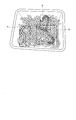
- FIG. 1 It is a perspective view of the state which grasped the arc-shaped part of the U-shaped work in the above-mentioned embodiment. It is a perspective view of the workpiece
- FIG. 1 shows a workpiece picking apparatus 1 according to an embodiment of the present invention.
- the workpiece take-out device 1 takes out the workpieces W stacked in the bucket 2 one by one by the robot arm 3A of the robot 3, and puts them in, for example, an automobile assembly line.
- Reference numeral 4 denotes a stereo camera.
- the stereo camera 4 is attached to the robot arm 3A of the robot 3.
- the stereo camera 4 acquires three-dimensional image information as viewed from the upper side of a large number of workpieces W having the same shape stacked on the bucket 2.
- Image information acquired by the stereo camera 4 is stored in the image information storage unit 5.
- the image information is an RGB value for each pixel, which is luminance information, and a distance (mm, cm) for each pixel, which is distance information.
- luminance information a distance (mm, cm) for each pixel, which is distance information.
- distance information in addition to luminance information may be obtained for each corresponding pixel by three-dimensional scanning with a laser or three-dimensional sensing with an image sensor capable of detecting distance.
- the image information storage unit 5 is connected to an edge detection unit 6 for performing edge detection in the image based on the stored image information.
- an image extraction unit 7 Connected to the edge detection unit 6 is an image extraction unit 7 that cuts out each partial image at the boundary part K (see FIG. 6) of the edge part obtained by edge detection, that is, the part of the workpiece W exposed to the outside Has been.
- the image extraction unit 7 selects several workpieces W that are relatively above the loosely stacked workpieces W and have a low degree of overlap. Here, the workpiece W on the top is selected from the images selected based on the distance information. This selection is selected at the time of detection by the edge detection unit 6.
- the cut out partial image is stored in the image information storage unit 5.
- Reference numeral 8 denotes a partial shape storage unit of the workpiece W.
- the partial shape storage unit 8 a partial shape existing in a part of the workpiece W to be handled and a gripping position of the partial shape are stored in advance. Priorities are assigned to the gripping positions of the partial shapes in order from the most appropriate part to grip. Although the priority order will be described later, the smaller the priority number is, the easier it is to grip without being caught by another workpiece W.
- the partial shape storage unit 8 stores in advance partial shape data of the workpiece W and priority order data for gripping.
- Reference numeral 9 denotes a matching determination unit.
- the matching determination unit 9 performs pattern matching between the image information of the part exposed to the outside of the workpiece W stored in the image information storage unit 5 and the partial shape stored in the partial shape storage unit 8 of the workpiece W by pattern matching. Judge whether to match.
- the gripping position setting unit 10 sets the partial shape of the workpiece W. The set part with the highest priority for gripping is set as the gripping position of the workpiece W.
- the grip position setting unit 10 is connected to a controller 11 that controls the operation of the robot arm 3A.
- clearance information around the gripping position included in the image information is also input to the gripping position setting unit 10 from the image information storage unit 5.
- a clearance is secured to allow the robot arm 3A to grasp the grasping position, that portion is grasped.
- viewing the clearance around the gripping position it can also be obtained from three-dimensional image information.
- 2A to 2D show typical partial shapes included in the workpiece W to be gripped and the priority order of gripping positions suitable for taking out. “Suitable for removal” means that it is difficult to be caught by another workpiece when it is taken out and is easy to be taken out, on the assumption that it is taken out in the direction where it is hardly caught.
- the priorities are ranked not only between the same partial shapes but also with different evaluations so that the ranks can be understood not only between the different partial shapes.
- FIG. 2A shows a U-shaped partial shape as one of the representative partial shapes included in the workpiece W.
- This U-shaped partial shape is easily caught with another workpiece W depending on the gripping position when the workpiece W is taken out from the bucket 2.
- This U-shaped shape is formed by an arc-shaped portion 20 and extending portions 21 and 21 extending from both ends of the arc-shaped portion 20 and parallel to each other.
- the arc-shaped portion 20 is the first priority.
- the second priority order is the straight portions 22, 22 connected to the arcuate portion 20.
- the third priority order is the straight line portions 23 and 23 including the end portions connected to the straight line portions 22 and 22. That is, as shown in FIG.
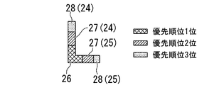
- FIG. 2B shows an L-shaped partial shape as one of the representative partial shapes included in the workpiece W.
- This partial shape is formed by connecting the long side portion 24 and the short piece portion 25 at a right angle.
- the first priority in the gripping position is the corner portion 26 of the long side portion 24 and the short piece portion 25.
- the second priority order is the straight portions 27 and 27 on the long side portion 24 side and the short piece portion 25 side adjacent to the corner portion 26.
- the third priority order is the straight line portions 28 and 28 including the end portions connected to the straight line portions 27 and 27.
- the partial shape is L-shaped such as a V-shape. It is not limited to shape workpieces.
- FIG. 2C shows an I-shaped partial shape as one of the representative partial shapes included in the workpiece W. Since this partial shape is a shape that is straight and difficult to catch, the priority of the gripping position starts from the second position, the second priority is the straight line portion 29 at both ends, and the third priority is the straight line portion 30 at the center. .
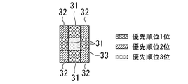
- FIG. 2D shows a plate-shaped square partial shape as one of the representative partial shapes included in the workpiece W.
- the first priority of the gripping position is the central portion 31 of each side excluding the central portion.
- Each corner portion 32 has the second highest priority.
- the central part 33 is the third priority.
- Such partial shapes of workpieces and priorities of gripping positions are stored in the partial shape storage unit 8 in advance.
- the first priority rank is indicated by cross hatching
- the second priority rank is indicated by hatching
- the third priority rank is indicated by point hatching.
- representative partial shape data included in the workpiece W to be grasped and priority order data of gripping positions corresponding to the representative partial shapes are stored in the partial shape storage unit. 8 is stored.
- the U-shaped data and the first priority ranking, second priority ranking, and third priority ranking of the gripping position are used.
- the data of each part is stored separately.
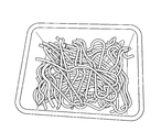
- the workpiece W stacked in the bucket 2 is photographed by the stereo camera 4 attached to the robot arm 3A of the robot 3 shown in FIG.
- the acquired image information of the part exposed to the outside is stored in the image information storage unit 5.
- the image information stored in the image information storage unit 5 is edge-detected by the edge detection unit 6, and the image area is also calculated.
- several workpieces W that are relatively high and have a relatively low degree of overlap, that is, workpieces W having a large area (here, three in order of increasing area) are selected. Therefore, the work W can be selected at high speed.
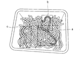
- the edge detection performed by the edge detection unit 6 can basically determine the portion having a large change rate of the luminance value as the boundary portion K in the image information.
- edge detection based only on luminance cannot be performed in this way, only images belonging to a predetermined distance range are extracted from image information having distance information. Then, edge detection can be performed using only the image information of the brightness corresponding to the extracted image.
- the boundary portion K is indicated by a bold line.
- the selected work W is extracted by the image extraction unit 7 and stored in the image information storage unit 5.
- the extracted image includes an area around the work W (indicated by three squares a, b, and c in FIG. 7). Therefore, the matching determination unit 9 determines whether or not the partial shape of the work W is narrowed down within this area and the representative partial shape stored in advance in the partial shape storage unit 8 is matched. Based on this result, a matching part is selected. In this way, since the area to be determined is narrowed down, the matching speed can be increased.
- the workpiece W having a matching portion is mapped with a portion having a high priority for gripping, as shown in FIG. 8.
- the gripping position can be quickly set.
- clearance information around the gripping position is input from the image information storage unit 5 to the gripping position setting unit 10. Only when there is a clearance for gripping the workpiece W as indicated by point hatching in the square a and square b regions in FIG.
- the clearance information Based on this, the gripping position is accurately calculated. Based on the calculation, a grip command is output to the controller 11. If the clearance is not sufficient, the grip position with the next highest priority is selected.
- the controller 11 that has received the command drives the robot 3 and uses the robot arm 3A to grip an optimum gripping position (a gripping position having a high priority) with a clearance of the workpiece W to be taken out. Thereby, the work W is taken out from the bucket 2.
- the embodiment it is not necessary to store the master model of the workpiece W. 1st priority showing the selected U-shaped, L-shaped, I-shaped, square-shaped and other representative partial shapes, and the degree of difficulty in catching each other shape with other workpieces W It is sufficient to store the third priority order in the partial shape storage unit 8. Therefore, the capacity of the database can be reduced, and there is an advantage that the configuration is simplified.
- the priorities indicating the pre-selected partial shapes such as U-shape, L-shape, I-shape, and square-shape and the degree of difficulty of being caught with other workpieces W when gripping each partial shape. It is set in stages from 1st to 3rd priority.
- the gripping position of the workpieces W stacked in bulk can be determined in a short time, and the workpieces W can be taken out quickly.
- the gripping position of the workpieces W stacked in bulk can be determined in a short time, and the workpieces W can be taken out quickly.
- the gripping position suitable for taking out for each part shape there is an effect of reliably preventing the work W being picked up from being caught by another work W.
- this invention is not restricted only to the said embodiment.
- the priority order of the gripping position it can be set in consideration of not only the shape but also the portion where the robot arm 3A of the robot 3 is easy to grip. Specifically, since a portion with less unevenness and a flat portion are easier to grip, it can be taken into account that there are less unevenness and flatness. Furthermore, since it is easy to hold as it is hard to slip, the difficulty of slipping and scratching can be taken into consideration in the priority order.
- four types are exemplified as typical partial shapes, the shape is not limited to four types.
- the priority is divided into three stages, the present invention is not limited to three stages.
- the workpiece removal method of the present invention it is possible to reliably remove the workpiece in a short time, and to prevent the workpiece from being caught by another workpiece, which contributes to speeding up the production line. Can do.
Landscapes
- Engineering & Computer Science (AREA)
- Robotics (AREA)
- Mechanical Engineering (AREA)
- Computer Vision & Pattern Recognition (AREA)
- Physics & Mathematics (AREA)
- General Physics & Mathematics (AREA)
- Theoretical Computer Science (AREA)
- Manipulator (AREA)
Abstract
ワーク取り出し方法は、代表的な部分形状と、前記代表的な部分形状中の一つまたは複数の把持位置と、各前記把持位置の優先順位とを記憶する工程と;積載された複数のワークをセンシングして画像情報を取得する工程と;前記画像情報のエッジ検出を行って、各ワークのうち、露出部分を認識する工程と;前記露出部分のうち、前記代表的な部分形状を備える露出部分を選択部分として選択する工程と;前記選択部分の中で、前記代表的な部分形状に一致する一つまたは複数の一致部分を検出する工程と;前記一致部分に含まれる一つまたは複数の前記把持位置から、最も把持に適する前記把持位置を、決定把持位置として、前記優先順位に基づいて決定する工程と;前記決定把持位置を把持するための把持指令を出力する工程と;を備える。
Description
この発明は、ワーク取り出し方法に関する。この発明は特に、バラ積みされて整列されていない状態の複数のワークの中から一つずつワークを取り出す場合に用いられるワーク取り出し方法に関する。
本願は、2008年10月10日に、日本に出願された特願2008-264030号に基づき優先権を主張し、その内容をここに援用する。
本願は、2008年10月10日に、日本に出願された特願2008-264030号に基づき優先権を主張し、その内容をここに援用する。
ロボットがワークを取り出す際、バラ積み状態とされたワークをカメラで撮影し、得られた2次元画像をマスタモデルと比較して、一致度が閾値以上である場合にそのワークを把持する技術が知られている(特許文献1参照)。記憶されているマスタモデルとしては、ワークの全体を含む第1のマスタモデルと把持位置に対応した第2のマスタモデルとがある。
上記関連技術においては、2次元画像を第1のマスタモデルに照合することにより把持可能候補となるワークを抽出する。そしてその後、抽出した把持可能ワークを第2マスタモデルに照合することにより、そのワークが把持可能かどうかを判断している。しかしながら、実際のバラ積みされたワークは重なり合って積載されている場合が多く、このような状態のワークの画像と、予め算出した把持姿勢とのマッチングは難しいという問題がある。また、細長い形状のワークや複雑な形状のワークは、取り出し時に他のワークに引っ掛かり、他のワークも一緒に取り出してしまう可能性が高い。従って、取り出し方向を考慮して好適な把持位置を選択する必要がある。
本発明は、上記課題に鑑み、短時間でワークの取り出しを行うことができ、かつワークを取り出す際に他のワークとの引っ掛かりを防止できるワーク取り出し方法を提供することを目的とする。
本発明は、上記課題を解決するために以下の手段を採用した。
(1)本発明のワーク取り出し方法は、代表的な部分形状と、前記代表的な部分形状中の一つまたは複数の把持位置と、各前記把持位置の優先順位とを記憶する工程と;積載された複数のワークをセンシングして画像情報を取得する工程と;前記画像情報のエッジ検出を行って、各ワークのうち、露出部分を認識する工程と;前記露出部分のうち、前記代表的な部分形状を備える露出部分を選択部分として選択する工程と;前記選択部分の中で、前記代表的な部分形状に一致する一つまたは複数の一致部分を検出する工程と;前記一致部分に含まれる一つまたは複数の前記把持位置から、最も把持に適する前記把持位置を、決定把持位置として、前記優先順位に基づいて決定する工程と;前記決定把持位置を把持するための把持指令を出力する工程と;を備える。
(2)上記(1)のワーク取り出し方法では、前記優先順位は、前記把持位置を把持して前記ワークを取り出す際の、他のワークへの引っ掛かり難さに従って設定しても良い。
(3)上記(1)のワーク取り出し方法では、前記優先順位は、前記把持位置の把持し易さに従って設定しても良い。
(4)上記(1)のワーク取り出し方法は、前記把持位置の周囲のクリアランス情報を取得する工程と:前記クリアランス情報に基づいて、クリアランスが不十分な場合には次に優先順位の高い前記把持位置を選択する工程と:を更に備えても良い。
上記(1)の発明によれば、予め選択された部分形状及び把持位置の優先順位を決めているため、バラ積みされたワークの把持位置を短時間で決定でき迅速にワークの取り出しを行うことができる。また、部分形状ごとで取り出しに適した把持位置の優先順位の高い部分を選択することにより、取り出しを行っているワークと他のワークとの引っ掛かりを確実に防止できる効果がある。
また、上記(2)~(3)の発明によれば、他のワークが引っ掛かり難い部分や、ロボットが把持し易い部分を把持位置として優先することで、スムーズにワークを把持できる効果がある。
また、上記(4)の発明によれば、クリアランスが十分なワーク把持箇所を選択できるため、スムーズにワークを把持できる効果がある。
また、上記(2)~(3)の発明によれば、他のワークが引っ掛かり難い部分や、ロボットが把持し易い部分を把持位置として優先することで、スムーズにワークを把持できる効果がある。
また、上記(4)の発明によれば、クリアランスが十分なワーク把持箇所を選択できるため、スムーズにワークを把持できる効果がある。
次に、この発明の実施形態を図面に基づいて説明する。図1はこの発明の実施形態のワーク取り出し装置1を示している。このワーク取り出し装置1はバケット2にバラ積みされたワークWをロボット3のロボットアーム3Aにより一個ずつ取り出して、例えば、自動車組立ラインに投入する。4はステレオカメラを示す。このステレオカメラ4はロボット3のロボットアーム3Aに取り付けられる。また、ステレオカメラ4は、バケット2に積載された多数の同一形状のワークWの上側から見て3次元の画像情報を取得する。
ステレオカメラ4により取得された画像情報は画像情報記憶部5に記憶される。ここで画像情報とは、輝度情報である各画素毎のRGB値と、距離情報である各画素毎の距離(mm,cm)である。尚、ステレオカメラ4に代えて、レーザによる3次元スキャンや、距離を検出できる画像センサによる3次元センシングにより、輝度情報に加えた距離情報を、対応する各画素毎に得るようにしてもよい。
ステレオカメラ4により取得された画像情報は画像情報記憶部5に記憶される。ここで画像情報とは、輝度情報である各画素毎のRGB値と、距離情報である各画素毎の距離(mm,cm)である。尚、ステレオカメラ4に代えて、レーザによる3次元スキャンや、距離を検出できる画像センサによる3次元センシングにより、輝度情報に加えた距離情報を、対応する各画素毎に得るようにしてもよい。
画像情報記憶部5には記憶された画像情報に基づいて画像におけるエッジ検出を行うためのエッジ検出部6が接続されている。エッジ検出部6にはエッジ検出により得られたエッジ部分、つまり外部に露出しているワークWの部分の境界部分K(図6参照)を境にして各部分画像を切り出す画像抽出部7が接続されている。この画像抽出部7により、バラ積みされたワークWのうち比較的上に存在し、重なり度合いが少ないワークWが数個選択される。ここで、上にあるワークWは、距離情報によって選別された画像の中から選択される。この選択はエッジ検出部6による検出時に選択される。切り出された部分画像は画像情報記憶部5に記憶される。
符号8はワークWの部分形状記憶部を示している。この部分形状記憶部8には、取り扱われるワークWの一部に存在する部分形状と、この部分形状の把持位置が、予め記憶されている。部分形状の各把持位置には把持することが最も適切な部位から順に優先順位が付けられている。優先順位については後述するが、優先順位の数字が小さい程他のワークWに引っ掛かること無く把持し易い部位となる。この部分形状記憶部8には予めワークWの部分形状データと把持のための優先順位データとが記憶される。
符号8はワークWの部分形状記憶部を示している。この部分形状記憶部8には、取り扱われるワークWの一部に存在する部分形状と、この部分形状の把持位置が、予め記憶されている。部分形状の各把持位置には把持することが最も適切な部位から順に優先順位が付けられている。優先順位については後述するが、優先順位の数字が小さい程他のワークWに引っ掛かること無く把持し易い部位となる。この部分形状記憶部8には予めワークWの部分形状データと把持のための優先順位データとが記憶される。
符号9はマッチング判定部を示している。このマッチング判定部9は、画像情報記憶部5に記憶されたワークWの外部に露出している部分の画像情報と、ワークWの部分形状記憶部8に記憶された部分形状とがパターンマッチングによりマッチングするか否かを判定する。マッチング判定部9によって、対象となるワークWに部分形状記憶部8に記憶された部分形状とマッチングする部位が存在すると判定された場合には、把持位置設定部10において、ワークWの部分形状に設定された把持のための優先順位の最も高い部分がそのワークWの把持位置として設定される。
把持位置設定部10はロボットアーム3Aの作動を制御するコントローラ11に接続されている。
ここで、把持位置設定部10には、画像情報記憶部5から画像情報に含まれる把持位置周辺のクリアランス情報も入力される。ロボットアーム3Aが把持位置を把持できるクリアランスが確保されていた場合に、その部分を把持する。ここで、把持位置周辺のクリアランスを見る場合には、3次元の画像情報から取得することもできる。しかし、ロボットアーム3Aを把持位置の近傍まで移動させて、角度を変えて画像情報を取得し、クリアランスの有無を確認することも可能である。
把持位置設定部10はロボットアーム3Aの作動を制御するコントローラ11に接続されている。
ここで、把持位置設定部10には、画像情報記憶部5から画像情報に含まれる把持位置周辺のクリアランス情報も入力される。ロボットアーム3Aが把持位置を把持できるクリアランスが確保されていた場合に、その部分を把持する。ここで、把持位置周辺のクリアランスを見る場合には、3次元の画像情報から取得することもできる。しかし、ロボットアーム3Aを把持位置の近傍まで移動させて、角度を変えて画像情報を取得し、クリアランスの有無を確認することも可能である。
図2A~図2Dは、把持対象となるワークWに含まれる代表的な部分形状と取り出しに適した把持位置の優先順位とを示している。取り出しに適したとは、最も引っ掛かり難い方向に取り出すことを前提に、取り出した際に他のワークに引っ掛かり難く、抜き出し易いことを意味する。また、優先順位は同一部分形状間だけではなく、異なる部分形状間においても序列がわかるように絶対評価で順位付けをしている。
図2Aは、ワークWに含まれる代表的な部分形状の一つとして、U字型の部分形状を示す。このU字型の部分形状はワークWをバケット2から取り出す場合に、把持位置の如何によっては他のワークWと引っ掛かり易い。このU字型形状は、弧状部20と、弧状部20の両端から伸び互いに平行な延出部21,21とで形成されている。このU字型の把持位置のうち、優先順位1位は弧状部20である。優先順位2位は弧状部20に連なる直線部22,22である。優先順位3位はこれら直線部22,22に連なる端部を含む直線部23,23である。
つまり、図3に示すように、端部を含む直線部23,23をロボットアーム3Aで把持すると、他のワークWの弧状部20が引っ掛かり易い。しかし、図4に示すように、弧状部20を把持すると引き抜き易く、他のワークWが引っ掛かる可能性が最も低い。尚、弧状部を有するワークであって、弧状部を把持することにより他のワークと引っ掛かり難く、引く抜き易くなる形状のワークであれば、J字型などのように部分形状がU字型の形状のワークに限られない。
つまり、図3に示すように、端部を含む直線部23,23をロボットアーム3Aで把持すると、他のワークWの弧状部20が引っ掛かり易い。しかし、図4に示すように、弧状部20を把持すると引き抜き易く、他のワークWが引っ掛かる可能性が最も低い。尚、弧状部を有するワークであって、弧状部を把持することにより他のワークと引っ掛かり難く、引く抜き易くなる形状のワークであれば、J字型などのように部分形状がU字型の形状のワークに限られない。
図2Bは、ワークWに含まれる代表的な部分形状の一つとして、L字型の部分形状を示す。この部分形状は、長辺部24と短片部25とが直角に接続されて形成されている。把持位置の優先順位1位は長辺部24と短片部25とのコーナー部分26である。優先順位2位はコーナー部分26に隣接する長辺部24側と短片部25側の直線部27,27である。優先順位3位はこれらの直線部27,27に連なる端部を含む直線部28,28である。尚、コーナー部分を有するワークであって、コーナー部分を把持することにより他のワークと引っ掛かり難く、引く抜き易くなる形状のワークであれば、V字型などのように部分形状がL字型の形状のワークに限られない。
図2Cは、ワークWに含まれる代表的な部分形状の一つとして、I字型の部分形状を示す。この部分形状は直線的であり引っ掛かり難い形状であるため、把持位置の優先順位は2位から始まり、優先順位2位は両端側の直線部29、優先順位3位は中央の直線部30である。
図2Dは、ワークWに含まれる代表的な部分形状の一つとして、板状の四角型の部分形状を示す。この部分形状では把持位置の優先順位1位は中央部を除く各辺の中央部分31である。優先順位2位は各コーナー部32である。優先順位3位は中央部33である。このようなワークの代表的な部分形状及び把持位置の優先順位は予め部分形状記憶部8に記憶されている。尚、図2A~図2Dにおいて優先順位1位はクロスハッチング、優先順位2位はハッチング、優先順位3位は点ハッチングで示す。
次に、バケット2にバラ積みされたワークWをロボット3のロボットアーム3Aで取り出す手順について説明する。
先ず、図2A~図2Dに示すように、把持対象となるワークWに含まれる代表的な部分形状データと、この代表的な部分形状に対応した把持位置の優先順位データとを部分形状記憶部8に記憶しておく。以下に示す例では、部分形状としてU字型の部分を備えたワークWを把持するため、このU字型のデータと、把持位置の優先順位1位、優先順位2位、優先順位3位の各部分のデータとをそれぞれ記憶しておく。
先ず、図2A~図2Dに示すように、把持対象となるワークWに含まれる代表的な部分形状データと、この代表的な部分形状に対応した把持位置の優先順位データとを部分形状記憶部8に記憶しておく。以下に示す例では、部分形状としてU字型の部分を備えたワークWを把持するため、このU字型のデータと、把持位置の優先順位1位、優先順位2位、優先順位3位の各部分のデータとをそれぞれ記憶しておく。
次に、図5に示すように、バケット2にバラ積みされたワークWを、図1に示すロボット3のロボットアーム3Aに取り付けられたステレオカメラ4で撮影する。取得された外部に露出している部分の画像情報は画像情報記憶部5に記憶される。
図6に示すように、画像情報記憶部5に記憶された画像情報はエッジ検出部6によってエッジ検出され、画像面積も算出される。そして、比較的上に位置するワークWで重なり度合いが比較的少ないワークW、つまり面積の大きいワークWが数個(ここでは面積の大きい順に3個)選択される。したがって、ワークWの選択を高速で行うことができる。
図6に示すように、画像情報記憶部5に記憶された画像情報はエッジ検出部6によってエッジ検出され、画像面積も算出される。そして、比較的上に位置するワークWで重なり度合いが比較的少ないワークW、つまり面積の大きいワークWが数個(ここでは面積の大きい順に3個)選択される。したがって、ワークWの選択を高速で行うことができる。
ここで、エッジ検出部6によって行われるエッジ検出は、画像情報において基本的に輝度の値の変化率が大きい部分を境界部分Kとして判定することができる。しかし、このように輝度のみによるエッジ検出ができない場合には、距離情報を有する画像情報において、所定の距離範囲内に属する画像だけを抽出する。そして、その抽出した画像に対応する輝度の画像情報のみを用いてエッジ検出することができる。尚、図6において、太線で示したのは境界部分Kである。
そして、選択されたワークWは画像抽出部7によって抽出されて画像情報記憶部5に記憶される。このとき、図7に示すように、抽出された画像にはワークWの周辺のエリア(図7に3つの四角a,b,cで示す)も含まれている。したがって、このエリア内に絞ってワークWの部分形状と、部分形状記憶部8に予め記憶されている代表的な部分形状とがマッチングしているか否かをマッチング判定部9によって判定する。この結果に基づいて、マッチングしている部分を選択する。このように、判定の対象となるエリアを絞っているためマッチング速度を速めることができる。
判定の結果、マッチングしている部分を備えたワークW(図7の点ハッチングの部分)について、図8に示すように、把持するための優先順位の高い部分をマッピングして把持位置設定部10により把持位置を優先順位に基づいて決定する(図8のクロスハッチング、ハッチング部分、点はハッチング部分)。したがって、形状によって優先順位が予め決定されているので、把持位置の設定を迅速に行うことができる。
ここで、把持位置設定部10には画像情報記憶部5から把持位置の周囲のクリアランス情報が入力される。図9の四角a、四角bの領域内に点ハッチングで示すように、ワークWを把持するクリアランスがある場合に限り(図8のクロスハッチング部分、ハッチング部分にのみクリアランスがある)、クリアランス情報に基づいて把持位置を正確に計算する。そしてその計算に基づいて、コントローラ11に把持指令を出力する。尚、クリアランスが十分でない場合には、次に優先順位の高い把持位置が選択される。
ここで、把持位置設定部10には画像情報記憶部5から把持位置の周囲のクリアランス情報が入力される。図9の四角a、四角bの領域内に点ハッチングで示すように、ワークWを把持するクリアランスがある場合に限り(図8のクロスハッチング部分、ハッチング部分にのみクリアランスがある)、クリアランス情報に基づいて把持位置を正確に計算する。そしてその計算に基づいて、コントローラ11に把持指令を出力する。尚、クリアランスが十分でない場合には、次に優先順位の高い把持位置が選択される。
そして、指令を受けたコントローラ11はロボット3を駆動し、ロボットアーム3Aによって、取り出すべきワークWのクリアランスのある最適な把持位置(優先順位の高い把持位置)を把持する。これにより、ワークWをバケット2から取り出す。
上記実施形態によれば、ワークWのマスタモデルを記憶しておく必要がない。選択されたU字型、L字型、I字型、四角型などの代表的な部分形状と、各部分形状について把持する際に他のワークWと引っ掛かり難い程度を示した優先順位1位~優先順位3位を、部分形状記憶部8に記憶しておけば十分である。従って、データベースの容量も少なくて済み、構成が簡素化するメリットがある。
また、予め選択されたU字型、L字型、I字型、四角型などの部分形状と、各部分形状について把持する際に他のワークWと引っ掛かり難い程度を示した優先順位を優先順位1位~優先順位3位と段階的に設定している。従って、バラ積みされたワークWの把持位置を短時間で決定でき、迅速にワークWの取り出しを行うことができる。また、部分形状毎で取り出しに適した把持位置の優先順位の高い部分を選択することにより、取り出しを行っているワークWと他のワークWとの引っ掛かりを確実に防止できる効果がある。
また、予め選択されたU字型、L字型、I字型、四角型などの部分形状と、各部分形状について把持する際に他のワークWと引っ掛かり難い程度を示した優先順位を優先順位1位~優先順位3位と段階的に設定している。従って、バラ積みされたワークWの把持位置を短時間で決定でき、迅速にワークWの取り出しを行うことができる。また、部分形状毎で取り出しに適した把持位置の優先順位の高い部分を選択することにより、取り出しを行っているワークWと他のワークWとの引っ掛かりを確実に防止できる効果がある。
また、ロボット3のロボットアーム3Aによりワークを把持するに先だって、ワークWの把持位置に把持するためのクリアランスが存在していることを条件にしている。このため、ワークWを確実に把持することができる。
また、把持位置に優先順位を付けているため、クリアランスが無くワークが把持できない場合には、順位を下げて把持位置を変更すれば良く、把持までの時間を短縮できる。
また、把持位置に優先順位を付けているため、クリアランスが無くワークが把持できない場合には、順位を下げて把持位置を変更すれば良く、把持までの時間を短縮できる。
尚、この発明は上記実施形態のみに限られるものではない。例えば、把持位置の優先順位を決定するにあたっては、形状のみならずロボット3のロボットアーム3Aが把持し易い部分であることを加味して設定することができる。具体的には凹凸が少ない部分、平坦な部分の方が把持し易いので、凹凸が少ないこと、平坦なことを条件に加味することができる。更に、滑り難い程把持し易いので、滑り難さや傷の付き難さを優先順位に加味することもできる。また、代表的な部分形状として4種類を例にしたが、4種類に限られるものではない。更に、優先順位を3段階に分けて説明したが、3段階に限られるものではない。
本発明のワーク取り出し方法によれば、短時間で確実にワークの取り出しを行うことができ、かつワークを取り出す際に他のワークとの引っ掛かりを防止できるため、製造ラインの高速化に寄与することができる。
1 ワーク取り出し装置
2 バケット
3 ロボット
3A ロボットアーム
4 ステレオカメラ
K 境界部分
W ワーク
2 バケット
3 ロボット
3A ロボットアーム
4 ステレオカメラ
K 境界部分
W ワーク
Claims (4)
- 代表的な部分形状と、前記代表的な部分形状中の一つまたは複数の把持位置と、各前記把持位置の優先順位とを記憶する工程と;
積載された複数のワークをセンシングして画像情報を取得する工程と;
前記画像情報のエッジ検出を行って、各ワークのうち、露出部分を認識する工程と;
前記露出部分のうち、前記代表的な部分形状を備える露出部分を選択部分として選択する工程と;
前記選択部分の中で、前記代表的な部分形状に一致する一つまたは複数の一致部分を検出する工程と;
前記一致部分に含まれる一つまたは複数の前記把持位置から、最も把持に適する前記把持位置を、決定把持位置として、前記優先順位に基づいて決定する工程と;
前記決定把持位置を把持するための把持指令を出力する工程と;
を備えたことを特徴とするワーク取り出し方法。 - 前記優先順位は、前記把持位置を把持して前記ワークを取り出す際の、他のワークへの引っ掛かり難さに従って設定することを特徴とする請求項1に記載のワーク取り出し方法。
- 前記優先順位は、前記把持位置の把持し易さに従って設定することを特徴とする請求項1に記載のワーク取り出し方法。
- 前記把持位置の周囲のクリアランス情報を取得する工程と;
前記クリアランス情報に基づいて、クリアランスが不十分な場合には次に優先順位の高い前記把持位置を選択する工程と;
を更に備えたことを特徴とする請求項1に記載のワーク取り出し方法。
Priority Applications (3)
| Application Number | Priority Date | Filing Date | Title |
|---|---|---|---|
| US13/122,761 US8504191B2 (en) | 2008-10-10 | 2009-09-03 | Method for picking up work pieces |
| CN200980137483.7A CN102164718B (zh) | 2008-10-10 | 2009-09-03 | 工件取出方法 |
| EP09818911.1A EP2345515B1 (en) | 2008-10-10 | 2009-09-03 | Method for picking up work pieces |
Applications Claiming Priority (2)
| Application Number | Priority Date | Filing Date | Title |
|---|---|---|---|
| JP2008264030A JP5265296B2 (ja) | 2008-10-10 | 2008-10-10 | ワーク取り出し方法 |
| JP2008-264030 | 2008-10-10 |
Publications (1)
| Publication Number | Publication Date |
|---|---|
| WO2010041371A1 true WO2010041371A1 (ja) | 2010-04-15 |
Family
ID=42100333
Family Applications (1)
| Application Number | Title | Priority Date | Filing Date |
|---|---|---|---|
| PCT/JP2009/004352 WO2010041371A1 (ja) | 2008-10-10 | 2009-09-03 | ワーク取り出し方法 |
Country Status (5)
| Country | Link |
|---|---|
| US (1) | US8504191B2 (ja) |
| EP (1) | EP2345515B1 (ja) |
| JP (1) | JP5265296B2 (ja) |
| CN (1) | CN102164718B (ja) |
| WO (1) | WO2010041371A1 (ja) |
Cited By (1)
| Publication number | Priority date | Publication date | Assignee | Title |
|---|---|---|---|---|
| CN104876021A (zh) * | 2014-02-28 | 2015-09-02 | 发那科株式会社 | 物品排列装置、物品排列方法以及物品转运系统 |
Families Citing this family (43)
| Publication number | Priority date | Publication date | Assignee | Title |
|---|---|---|---|---|
| JP5522532B2 (ja) * | 2010-05-25 | 2014-06-18 | 株式会社Ihi | 切削部を有するワークの把持装置及び把持方法 |
| KR101778030B1 (ko) * | 2010-09-27 | 2017-09-26 | 삼성전자주식회사 | 로봇 및 그 제어방법 |
| US9089966B2 (en) | 2010-11-17 | 2015-07-28 | Mitsubishi Electric Corporation | Workpiece pick-up apparatus |
| JP5767464B2 (ja) * | 2010-12-15 | 2015-08-19 | キヤノン株式会社 | 情報処理装置、情報処理装置の制御方法、およびプログラム |
| FI20106387A (fi) | 2010-12-30 | 2012-07-01 | Zenrobotics Oy | Menetelmä, tietokoneohjelma ja laite tartuntakohdan määrittämiseksi |
| JP5533727B2 (ja) * | 2011-02-18 | 2014-06-25 | 株式会社安川電機 | ワークピッキングシステム |
| JP5879704B2 (ja) * | 2011-03-10 | 2016-03-08 | 富士電機株式会社 | ロボット制御装置、物品取り出しシステム、プログラムおよびロボットの制御方法 |
| US9469035B2 (en) | 2011-06-29 | 2016-10-18 | Mitsubishi Electric Corporation | Component supply apparatus |
| JP5852364B2 (ja) | 2011-08-26 | 2016-02-03 | キヤノン株式会社 | 情報処理装置、情報処理装置の制御方法、およびプログラム |
| JP5936108B2 (ja) * | 2011-12-06 | 2016-06-15 | 株式会社Ihi | 対象物取り出し装置と方法 |
| DE102013013114A1 (de) * | 2012-08-17 | 2014-02-20 | Liebherr-Verzahntechnik Gmbh | Vorrichtung zum automatisierten Entnehmen von in einem Behälter angeordneten Werkstücken |
| JP5641084B2 (ja) * | 2013-03-18 | 2014-12-17 | 株式会社安川電機 | ロボットシステムおよび被加工物の製造方法 |
| JP5754454B2 (ja) * | 2013-03-18 | 2015-07-29 | 株式会社安川電機 | ロボットピッキングシステム及び被加工物の製造方法 |
| JP6170345B2 (ja) * | 2013-06-03 | 2017-07-26 | 株式会社アマダホールディングス | 自動補正システム及びその方法 |
| JP5786896B2 (ja) * | 2013-06-07 | 2015-09-30 | 株式会社安川電機 | ワーク検出装置、ロボットシステム、被加工物の製造方法及びワーク検出方法 |
| JP6016716B2 (ja) * | 2013-06-12 | 2016-10-26 | 三菱電機株式会社 | ビンピッキング性能評価装置及び方法 |
| JP6176091B2 (ja) * | 2013-12-02 | 2017-08-09 | トヨタ自動車株式会社 | 把持方法、運搬方法及びロボット |
| JP6357785B2 (ja) * | 2014-02-04 | 2018-07-18 | セイコーエプソン株式会社 | ロボット、ロボットシステム、制御装置および制御方法 |
| JP6541397B2 (ja) * | 2015-04-06 | 2019-07-10 | キヤノン株式会社 | 情報処理装置、情報処理方法、およびプログラム |
| JP6632224B2 (ja) * | 2015-06-02 | 2020-01-22 | キヤノン株式会社 | 把持制御装置、把持制御方法及びプログラム |
| US10850393B2 (en) | 2015-07-08 | 2020-12-01 | Universal Robots A/S | Method for extending end user programming of an industrial robot with third party contributions |
| CN106466848A (zh) * | 2015-08-21 | 2017-03-01 | 沈昌余 | 机械手末端机构及取卸料方案 |
| CN105014658B (zh) * | 2015-08-22 | 2017-06-09 | 衢州市立掏智能科技有限公司 | 自动取卸物件的方法 |
| CN105598966B (zh) * | 2016-01-12 | 2019-02-05 | 重庆世纪精信实业(集团)有限公司 | 基于可调节抱具的自动调节系统及其方法 |
| CN105598967B (zh) * | 2016-01-12 | 2019-01-01 | 重庆世纪精信实业(集团)有限公司 | 基于可调节抱具的智能提示系统及方法 |
| JP7047249B2 (ja) * | 2017-01-10 | 2022-04-05 | オムロン株式会社 | 画像処理システム、画像処理装置、ワークのピックアップ方法、および、ワークのピックアッププログラム |
| EP3569368A4 (en) * | 2017-01-12 | 2020-01-22 | Fuji Corporation | WORKING MACHINE AND RECORDING POSITION SELECTION PROCEDURE |
| WO2018185857A1 (ja) * | 2017-04-04 | 2018-10-11 | 株式会社Mujin | 情報処理装置、ピッキングシステム、物流システム、プログラム、及び、情報処理方法 |
| DE112017007398B4 (de) | 2017-04-04 | 2021-11-18 | Mujin, Inc. | Steuervorrichtung, Greifsystem, Verteilersystem, Programm und Steuerverfahren |
| CN115385039A (zh) | 2017-04-04 | 2022-11-25 | 牧今科技 | 控制装置、信息处理装置、控制方法以及信息处理方法 |
| JP6325174B1 (ja) | 2017-04-04 | 2018-05-16 | 株式会社Mujin | 制御装置、ピッキングシステム、物流システム、プログラム、制御方法、及び、生産方法 |
| DE112017007392B4 (de) | 2017-04-04 | 2021-11-04 | Mujin, Inc. | Steuervorrichtung, Greifsystem, Verteilersystem, Programm, Steuerverfahren und Herstellungsverfahren |
| JP6487495B2 (ja) | 2017-05-19 | 2019-03-20 | ファナック株式会社 | ワーク取出しシステム |
| JP6880457B2 (ja) | 2017-11-14 | 2021-06-02 | オムロン株式会社 | 把持方法、把持システム及びプログラム |
| JP7467041B2 (ja) * | 2018-09-27 | 2024-04-15 | キヤノン株式会社 | 情報処理装置、情報処理方法及びシステム |
| TWI677415B (zh) * | 2019-01-24 | 2019-11-21 | 上銀科技股份有限公司 | 排除隨機堆疊之複數個工件之干涉的系統 |
| US11485015B2 (en) | 2019-02-21 | 2022-11-01 | Hiwin Technologies Corp. | System for eliminating interference of randomly stacked workpieces |
| JP7113778B2 (ja) * | 2019-03-27 | 2022-08-05 | Ntn株式会社 | ワーク取り出し作業装置 |
| JP7376268B2 (ja) | 2019-07-22 | 2023-11-08 | ファナック株式会社 | 三次元データ生成装置及びロボット制御システム |
| JP7351667B2 (ja) | 2019-08-01 | 2023-09-27 | ファナック株式会社 | 複数点嵌合を行うロボット制御システム、制御方法、コンピュータのプログラム、および制御装置 |
| US20220241982A1 (en) * | 2019-09-18 | 2022-08-04 | Fuji Corporation | Work robot and work system |
| SE544103C2 (en) | 2020-10-28 | 2021-12-21 | Zenrobotics Oy | Waste Sorting Robot with gripper that releases waste object at a throw position |
| WO2024047711A1 (ja) * | 2022-08-29 | 2024-03-07 | ファナック株式会社 | 取り出し機械制御装置、取り出し機械制御プログラムおよび取り出し機械システム |
Citations (6)
| Publication number | Priority date | Publication date | Assignee | Title |
|---|---|---|---|---|
| JPH07319525A (ja) * | 1994-05-25 | 1995-12-08 | Nippondenso Co Ltd | 山積み部品の高速ピッキング装置 |
| JP2002200588A (ja) | 2000-12-28 | 2002-07-16 | Denso Corp | ロボットによる把持可能部品の把持位置検出方法及びその装置 |
| JP2004188562A (ja) * | 2002-12-13 | 2004-07-08 | Fanuc Ltd | ワーク取出し装置 |
| JP2004188533A (ja) * | 2002-12-10 | 2004-07-08 | Toyota Motor Corp | 対象物の取扱い推定方法および取扱い推定装置 |
| JP2004230513A (ja) * | 2003-01-30 | 2004-08-19 | Fanuc Ltd | ワーク取出し装置 |
| JP2005305613A (ja) * | 2004-04-23 | 2005-11-04 | Fanuc Ltd | 物品取出し装置 |
Family Cites Families (6)
| Publication number | Priority date | Publication date | Assignee | Title |
|---|---|---|---|---|
| GB2261069B (en) | 1991-10-30 | 1995-11-01 | Nippon Denso Co | High speed picking system for stacked parts |
| JP3768174B2 (ja) | 2002-07-24 | 2006-04-19 | ファナック株式会社 | ワーク取出し装置 |
| JP4087874B2 (ja) * | 2006-02-01 | 2008-05-21 | ファナック株式会社 | ワーク取り出し装置 |
| JP4226623B2 (ja) * | 2006-09-29 | 2009-02-18 | ファナック株式会社 | ワーク取り出し装置 |
| CN100519103C (zh) | 2008-05-12 | 2009-07-29 | 刘朝轩 | 一种方便抓取工件的单配重机械手 |
| US8165929B2 (en) * | 2008-08-04 | 2012-04-24 | Chudy Group, LLC | Adaptive pharmaceutical product management methods and system |
-
2008
- 2008-10-10 JP JP2008264030A patent/JP5265296B2/ja not_active Expired - Fee Related
-
2009
- 2009-09-03 CN CN200980137483.7A patent/CN102164718B/zh not_active Expired - Fee Related
- 2009-09-03 US US13/122,761 patent/US8504191B2/en active Active
- 2009-09-03 WO PCT/JP2009/004352 patent/WO2010041371A1/ja active Application Filing
- 2009-09-03 EP EP09818911.1A patent/EP2345515B1/en not_active Not-in-force
Patent Citations (6)
| Publication number | Priority date | Publication date | Assignee | Title |
|---|---|---|---|---|
| JPH07319525A (ja) * | 1994-05-25 | 1995-12-08 | Nippondenso Co Ltd | 山積み部品の高速ピッキング装置 |
| JP2002200588A (ja) | 2000-12-28 | 2002-07-16 | Denso Corp | ロボットによる把持可能部品の把持位置検出方法及びその装置 |
| JP2004188533A (ja) * | 2002-12-10 | 2004-07-08 | Toyota Motor Corp | 対象物の取扱い推定方法および取扱い推定装置 |
| JP2004188562A (ja) * | 2002-12-13 | 2004-07-08 | Fanuc Ltd | ワーク取出し装置 |
| JP2004230513A (ja) * | 2003-01-30 | 2004-08-19 | Fanuc Ltd | ワーク取出し装置 |
| JP2005305613A (ja) * | 2004-04-23 | 2005-11-04 | Fanuc Ltd | 物品取出し装置 |
Non-Patent Citations (1)
| Title |
|---|
| See also references of EP2345515A4 * |
Cited By (3)
| Publication number | Priority date | Publication date | Assignee | Title |
|---|---|---|---|---|
| CN104876021A (zh) * | 2014-02-28 | 2015-09-02 | 发那科株式会社 | 物品排列装置、物品排列方法以及物品转运系统 |
| JP2015214012A (ja) * | 2014-02-28 | 2015-12-03 | ファナック株式会社 | ロボットを用いて物品を整列させる物品整列装置及び物品整列方法、並びに物品整列装置を備えた物品移送システム |
| US9643796B2 (en) | 2014-02-28 | 2017-05-09 | Fanuc Corporation | Device and method of arraying articles by using robot, and article transfer system |
Also Published As
| Publication number | Publication date |
|---|---|
| US20110251717A1 (en) | 2011-10-13 |
| JP5265296B2 (ja) | 2013-08-14 |
| EP2345515A4 (en) | 2012-03-07 |
| US8504191B2 (en) | 2013-08-06 |
| JP2010089238A (ja) | 2010-04-22 |
| EP2345515B1 (en) | 2013-04-17 |
| CN102164718A (zh) | 2011-08-24 |
| CN102164718B (zh) | 2014-10-22 |
| EP2345515A1 (en) | 2011-07-20 |
Similar Documents
| Publication | Publication Date | Title |
|---|---|---|
| WO2010041371A1 (ja) | ワーク取り出し方法 | |
| US9957120B2 (en) | Stowage pattern calculation device and stowage device for stowing plurality types of objects | |
| EP1816604B1 (en) | Workpiece picking device | |
| US8380342B2 (en) | Workpiece removing device and method | |
| JP4199264B2 (ja) | ワーク取り出し装置及び方法 | |
| CN101152720B (zh) | 工件取出装置 | |
| WO2023035832A1 (zh) | 一种基于视觉识别的机器人分拣方法及存储介质 | |
| JP5088278B2 (ja) | 物体検出方法と物体検出装置およびロボットシステム | |
| JP2019136828A (ja) | 箱状物ピッキング装置及びその方法 | |
| JP4866890B2 (ja) | ワーク形状推定装置 | |
| WO2020158060A1 (ja) | 物体把持システム | |
| CN110167723A (zh) | 作业机及拾取位置选择方法 | |
| CN111687060B (zh) | 一种物流多级分拣系统及方法 | |
| CN113269112A (zh) | 一种抓取区域的识别方法、装置、电子设备及存储介质 | |
| JP6632224B2 (ja) | 把持制御装置、把持制御方法及びプログラム | |
| WO2020049774A1 (ja) | マニピュレータおよび移動ロボット | |
| CN111508014A (zh) | 排除随机堆叠的多个工件的干涉的系统 | |
| TWI677415B (zh) | 排除隨機堆疊之複數個工件之干涉的系統 | |
| US20240351196A1 (en) | Method for handling objects and handling system | |
| CN117383109A (zh) | 物体夹持顺序确定方法、装置、设备及存储介质 | |
| TW202432319A (zh) | 機器人控制裝置、機器人系統及機器人控制程式 |
Legal Events
| Date | Code | Title | Description |
|---|---|---|---|
| WWE | Wipo information: entry into national phase |
Ref document number: 200980137483.7 Country of ref document: CN |
|
| 121 | Ep: the epo has been informed by wipo that ep was designated in this application |
Ref document number: 09818911 Country of ref document: EP Kind code of ref document: A1 |
|
| NENP | Non-entry into the national phase |
Ref country code: DE |
|
| WWE | Wipo information: entry into national phase |
Ref document number: 2009818911 Country of ref document: EP |
|
| WWE | Wipo information: entry into national phase |
Ref document number: 13122761 Country of ref document: US |