WO2010041371A1 - Procédé d’extraction de pièce - Google Patents
Procédé d’extraction de pièce Download PDFInfo
- Publication number
- WO2010041371A1 WO2010041371A1 PCT/JP2009/004352 JP2009004352W WO2010041371A1 WO 2010041371 A1 WO2010041371 A1 WO 2010041371A1 JP 2009004352 W JP2009004352 W JP 2009004352W WO 2010041371 A1 WO2010041371 A1 WO 2010041371A1
- Authority
- WO
- WIPO (PCT)
- Prior art keywords
- workpiece
- gripping
- priority
- partial shape
- work
- Prior art date
Links
Images


Classifications
-
- B—PERFORMING OPERATIONS; TRANSPORTING
- B25—HAND TOOLS; PORTABLE POWER-DRIVEN TOOLS; MANIPULATORS
- B25J—MANIPULATORS; CHAMBERS PROVIDED WITH MANIPULATION DEVICES
- B25J9/00—Programme-controlled manipulators
- B25J9/16—Programme controls
- B25J9/1694—Programme controls characterised by use of sensors other than normal servo-feedback from position, speed or acceleration sensors, perception control, multi-sensor controlled systems, sensor fusion
- B25J9/1697—Vision controlled systems
-
- B—PERFORMING OPERATIONS; TRANSPORTING
- B25—HAND TOOLS; PORTABLE POWER-DRIVEN TOOLS; MANIPULATORS
- B25J—MANIPULATORS; CHAMBERS PROVIDED WITH MANIPULATION DEVICES
- B25J9/00—Programme-controlled manipulators
- B25J9/16—Programme controls
- B25J9/1679—Programme controls characterised by the tasks executed
- B25J9/1687—Assembly, peg and hole, palletising, straight line, weaving pattern movement
-
- G—PHYSICS
- G06—COMPUTING; CALCULATING OR COUNTING
- G06T—IMAGE DATA PROCESSING OR GENERATION, IN GENERAL
- G06T7/00—Image analysis
- G06T7/70—Determining position or orientation of objects or cameras
- G06T7/73—Determining position or orientation of objects or cameras using feature-based methods
- G06T7/75—Determining position or orientation of objects or cameras using feature-based methods involving models
-
- G—PHYSICS
- G05—CONTROLLING; REGULATING
- G05B—CONTROL OR REGULATING SYSTEMS IN GENERAL; FUNCTIONAL ELEMENTS OF SUCH SYSTEMS; MONITORING OR TESTING ARRANGEMENTS FOR SUCH SYSTEMS OR ELEMENTS
- G05B2219/00—Program-control systems
- G05B2219/30—Nc systems
- G05B2219/40—Robotics, robotics mapping to robotics vision
- G05B2219/40053—Pick 3-D object from pile of objects
-
- G—PHYSICS
- G05—CONTROLLING; REGULATING
- G05B—CONTROL OR REGULATING SYSTEMS IN GENERAL; FUNCTIONAL ELEMENTS OF SUCH SYSTEMS; MONITORING OR TESTING ARRANGEMENTS FOR SUCH SYSTEMS OR ELEMENTS
- G05B2219/00—Program-control systems
- G05B2219/30—Nc systems
- G05B2219/45—Nc applications
- G05B2219/45063—Pick and place manipulator
-
- G—PHYSICS
- G06—COMPUTING; CALCULATING OR COUNTING
- G06T—IMAGE DATA PROCESSING OR GENERATION, IN GENERAL
- G06T2207/00—Indexing scheme for image analysis or image enhancement
- G06T2207/30—Subject of image; Context of image processing
- G06T2207/30108—Industrial image inspection
- G06T2207/30164—Workpiece; Machine component
Definitions
- the present invention relates to a workpiece picking method.
- the present invention relates to a work picking method used when picking up works one by one from a plurality of work pieces that are stacked and not aligned.
- the stored master models include a first master model that includes the entire workpiece and a second master model that corresponds to the gripping position.
- a workpiece that is a grippable candidate is extracted by collating the two-dimensional image with the first master model. After that, by comparing the extracted grippable workpiece with the second master model, it is determined whether or not the workpiece can be gripped.
- the workpiece can be gripped.
- there are many cases in which actual stacked workpieces are stacked and stacked and there is a problem that it is difficult to match an image of a workpiece in such a state with a gripping posture calculated in advance.
- it is highly likely that an elongated workpiece or a workpiece having a complicated shape is caught by another workpiece when taken out, and the other workpiece is taken out together. Therefore, it is necessary to select a suitable gripping position in consideration of the take-out direction.
- an object of the present invention is to provide a work picking method that can pick up a work in a short time and can prevent catching with another work when picking up the work.
- a method of taking out a workpiece according to the present invention includes a step of storing a representative partial shape, one or a plurality of gripping positions in the representative partial shape, and a priority order of each gripping position; Sensing a plurality of workpieces obtained to obtain image information; performing edge detection of the image information to recognize an exposed portion of each workpiece; and representative of the exposed portions Selecting an exposed portion having a partial shape as a selected portion; detecting one or more matching portions in the selected portion that match the representative partial shape; and included in the matching portion Determining a gripping position most suitable for gripping as a determined gripping position based on the priority order from one or a plurality of gripping positions; and outputting a gripping command for gripping the determined gripping position.
- the priority may be set according to the difficulty of being caught on another workpiece when the gripping position is gripped and the workpiece is picked up.
- the priority may be set according to the ease of gripping of the gripping position.
- the workpiece picking method according to (1) includes a step of obtaining clearance information around the gripping position; and, based on the clearance information, when the clearance is insufficient, the gripping with the next highest priority is performed. And a step of selecting a position.
- the gripping position of the stacked workpieces can be determined in a short time and the workpiece can be taken out quickly. Can do.
- the gripping position of the stacked workpieces can be determined in a short time and the workpiece can be taken out quickly. Can do.
- by selecting a part with a high priority of the gripping position suitable for taking out for each part shape there is an effect of reliably preventing the work being taken out from being caught by another work.
- the invention of (4) since a work gripping portion having a sufficient clearance can be selected, there is an effect that the work can be gripped smoothly.
- FIG. 1 It is a perspective view of the state which grasped the arc-shaped part of the U-shaped work in the above-mentioned embodiment. It is a perspective view of the workpiece
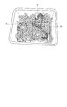
- FIG. 1 shows a workpiece picking apparatus 1 according to an embodiment of the present invention.
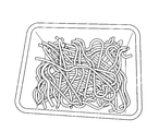
- the workpiece take-out device 1 takes out the workpieces W stacked in the bucket 2 one by one by the robot arm 3A of the robot 3, and puts them in, for example, an automobile assembly line.
- Reference numeral 4 denotes a stereo camera.
- the stereo camera 4 is attached to the robot arm 3A of the robot 3.
- the stereo camera 4 acquires three-dimensional image information as viewed from the upper side of a large number of workpieces W having the same shape stacked on the bucket 2.
- Image information acquired by the stereo camera 4 is stored in the image information storage unit 5.
- the image information is an RGB value for each pixel, which is luminance information, and a distance (mm, cm) for each pixel, which is distance information.
- luminance information a distance (mm, cm) for each pixel, which is distance information.
- distance information in addition to luminance information may be obtained for each corresponding pixel by three-dimensional scanning with a laser or three-dimensional sensing with an image sensor capable of detecting distance.
- the image information storage unit 5 is connected to an edge detection unit 6 for performing edge detection in the image based on the stored image information.
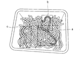
- an image extraction unit 7 Connected to the edge detection unit 6 is an image extraction unit 7 that cuts out each partial image at the boundary part K (see FIG. 6) of the edge part obtained by edge detection, that is, the part of the workpiece W exposed to the outside Has been.
- the image extraction unit 7 selects several workpieces W that are relatively above the loosely stacked workpieces W and have a low degree of overlap. Here, the workpiece W on the top is selected from the images selected based on the distance information. This selection is selected at the time of detection by the edge detection unit 6.
- the cut out partial image is stored in the image information storage unit 5.
- Reference numeral 8 denotes a partial shape storage unit of the workpiece W.
- the partial shape storage unit 8 a partial shape existing in a part of the workpiece W to be handled and a gripping position of the partial shape are stored in advance. Priorities are assigned to the gripping positions of the partial shapes in order from the most appropriate part to grip. Although the priority order will be described later, the smaller the priority number is, the easier it is to grip without being caught by another workpiece W.
- the partial shape storage unit 8 stores in advance partial shape data of the workpiece W and priority order data for gripping.
- Reference numeral 9 denotes a matching determination unit.
- the matching determination unit 9 performs pattern matching between the image information of the part exposed to the outside of the workpiece W stored in the image information storage unit 5 and the partial shape stored in the partial shape storage unit 8 of the workpiece W by pattern matching. Judge whether to match.
- the gripping position setting unit 10 sets the partial shape of the workpiece W. The set part with the highest priority for gripping is set as the gripping position of the workpiece W.
- the grip position setting unit 10 is connected to a controller 11 that controls the operation of the robot arm 3A.
- clearance information around the gripping position included in the image information is also input to the gripping position setting unit 10 from the image information storage unit 5.
- a clearance is secured to allow the robot arm 3A to grasp the grasping position, that portion is grasped.
- viewing the clearance around the gripping position it can also be obtained from three-dimensional image information.
- 2A to 2D show typical partial shapes included in the workpiece W to be gripped and the priority order of gripping positions suitable for taking out. “Suitable for removal” means that it is difficult to be caught by another workpiece when it is taken out and is easy to be taken out, on the assumption that it is taken out in the direction where it is hardly caught.
- the priorities are ranked not only between the same partial shapes but also with different evaluations so that the ranks can be understood not only between the different partial shapes.
- FIG. 2A shows a U-shaped partial shape as one of the representative partial shapes included in the workpiece W.
- This U-shaped partial shape is easily caught with another workpiece W depending on the gripping position when the workpiece W is taken out from the bucket 2.
- This U-shaped shape is formed by an arc-shaped portion 20 and extending portions 21 and 21 extending from both ends of the arc-shaped portion 20 and parallel to each other.
- the arc-shaped portion 20 is the first priority.
- the second priority order is the straight portions 22, 22 connected to the arcuate portion 20.
- the third priority order is the straight line portions 23 and 23 including the end portions connected to the straight line portions 22 and 22. That is, as shown in FIG.
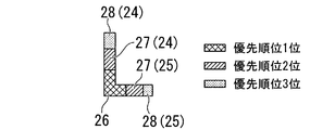
- FIG. 2B shows an L-shaped partial shape as one of the representative partial shapes included in the workpiece W.
- This partial shape is formed by connecting the long side portion 24 and the short piece portion 25 at a right angle.
- the first priority in the gripping position is the corner portion 26 of the long side portion 24 and the short piece portion 25.
- the second priority order is the straight portions 27 and 27 on the long side portion 24 side and the short piece portion 25 side adjacent to the corner portion 26.
- the third priority order is the straight line portions 28 and 28 including the end portions connected to the straight line portions 27 and 27.
- the partial shape is L-shaped such as a V-shape. It is not limited to shape workpieces.
- FIG. 2C shows an I-shaped partial shape as one of the representative partial shapes included in the workpiece W. Since this partial shape is a shape that is straight and difficult to catch, the priority of the gripping position starts from the second position, the second priority is the straight line portion 29 at both ends, and the third priority is the straight line portion 30 at the center. .
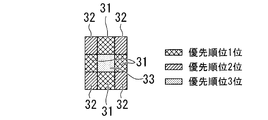
- FIG. 2D shows a plate-shaped square partial shape as one of the representative partial shapes included in the workpiece W.
- the first priority of the gripping position is the central portion 31 of each side excluding the central portion.
- Each corner portion 32 has the second highest priority.
- the central part 33 is the third priority.
- Such partial shapes of workpieces and priorities of gripping positions are stored in the partial shape storage unit 8 in advance.
- the first priority rank is indicated by cross hatching
- the second priority rank is indicated by hatching
- the third priority rank is indicated by point hatching.
- representative partial shape data included in the workpiece W to be grasped and priority order data of gripping positions corresponding to the representative partial shapes are stored in the partial shape storage unit. 8 is stored.
- the U-shaped data and the first priority ranking, second priority ranking, and third priority ranking of the gripping position are used.
- the data of each part is stored separately.
- the workpiece W stacked in the bucket 2 is photographed by the stereo camera 4 attached to the robot arm 3A of the robot 3 shown in FIG.
- the acquired image information of the part exposed to the outside is stored in the image information storage unit 5.
- the image information stored in the image information storage unit 5 is edge-detected by the edge detection unit 6, and the image area is also calculated.
- several workpieces W that are relatively high and have a relatively low degree of overlap, that is, workpieces W having a large area (here, three in order of increasing area) are selected. Therefore, the work W can be selected at high speed.
- the edge detection performed by the edge detection unit 6 can basically determine the portion having a large change rate of the luminance value as the boundary portion K in the image information.
- edge detection based only on luminance cannot be performed in this way, only images belonging to a predetermined distance range are extracted from image information having distance information. Then, edge detection can be performed using only the image information of the brightness corresponding to the extracted image.
- the boundary portion K is indicated by a bold line.
- the selected work W is extracted by the image extraction unit 7 and stored in the image information storage unit 5.
- the extracted image includes an area around the work W (indicated by three squares a, b, and c in FIG. 7). Therefore, the matching determination unit 9 determines whether or not the partial shape of the work W is narrowed down within this area and the representative partial shape stored in advance in the partial shape storage unit 8 is matched. Based on this result, a matching part is selected. In this way, since the area to be determined is narrowed down, the matching speed can be increased.
- the workpiece W having a matching portion is mapped with a portion having a high priority for gripping, as shown in FIG. 8.
- the gripping position can be quickly set.
- clearance information around the gripping position is input from the image information storage unit 5 to the gripping position setting unit 10. Only when there is a clearance for gripping the workpiece W as indicated by point hatching in the square a and square b regions in FIG.
- the clearance information Based on this, the gripping position is accurately calculated. Based on the calculation, a grip command is output to the controller 11. If the clearance is not sufficient, the grip position with the next highest priority is selected.
- the controller 11 that has received the command drives the robot 3 and uses the robot arm 3A to grip an optimum gripping position (a gripping position having a high priority) with a clearance of the workpiece W to be taken out. Thereby, the work W is taken out from the bucket 2.
- the embodiment it is not necessary to store the master model of the workpiece W. 1st priority showing the selected U-shaped, L-shaped, I-shaped, square-shaped and other representative partial shapes, and the degree of difficulty in catching each other shape with other workpieces W It is sufficient to store the third priority order in the partial shape storage unit 8. Therefore, the capacity of the database can be reduced, and there is an advantage that the configuration is simplified.
- the priorities indicating the pre-selected partial shapes such as U-shape, L-shape, I-shape, and square-shape and the degree of difficulty of being caught with other workpieces W when gripping each partial shape. It is set in stages from 1st to 3rd priority.
- the gripping position of the workpieces W stacked in bulk can be determined in a short time, and the workpieces W can be taken out quickly.
- the gripping position of the workpieces W stacked in bulk can be determined in a short time, and the workpieces W can be taken out quickly.
- the gripping position suitable for taking out for each part shape there is an effect of reliably preventing the work W being picked up from being caught by another work W.
- this invention is not restricted only to the said embodiment.
- the priority order of the gripping position it can be set in consideration of not only the shape but also the portion where the robot arm 3A of the robot 3 is easy to grip. Specifically, since a portion with less unevenness and a flat portion are easier to grip, it can be taken into account that there are less unevenness and flatness. Furthermore, since it is easy to hold as it is hard to slip, the difficulty of slipping and scratching can be taken into consideration in the priority order.
- four types are exemplified as typical partial shapes, the shape is not limited to four types.
- the priority is divided into three stages, the present invention is not limited to three stages.
- the workpiece removal method of the present invention it is possible to reliably remove the workpiece in a short time, and to prevent the workpiece from being caught by another workpiece, which contributes to speeding up the production line. Can do.
Landscapes
- Engineering & Computer Science (AREA)
- Robotics (AREA)
- Mechanical Engineering (AREA)
- Computer Vision & Pattern Recognition (AREA)
- Physics & Mathematics (AREA)
- General Physics & Mathematics (AREA)
- Theoretical Computer Science (AREA)
- Manipulator (AREA)
Abstract
L'invention concerne un procédé d’extraction d’une pièce, comportant : une étape consistant à mémoriser une forme partielle représentative, une ou plusieurs positions de maintien dans la forme partielle représentative et une priorité associée à chaque position de maintien ; une étape consistant à acquérir des informations d’image en détectant une pluralité de pièces superposées ; une étape consistant à détecter des bords à partir des informations d’image et à reconnaître des sections découvertes de chaque pièce ; une étape consistant à sélectionner, en tant que section sélectionnée, la section découverte possédant la forme partielle représentative parmi les sections découvertes ; une étape consistant à détecter une ou plusieurs sections correspondant à la forme partielle représentative dans la section sélectionnée ; une étape consistant à déterminer, en tant que position de maintien déterminée sur la base de la priorité, la position de maintien la plus appropriée pour le maintien parmi une ou plusieurs positions de maintien comprises dans les sections correspondantes ; et une étape consistant à émettre une instruction de maintien afin de maintenir la pièce dans les positions de maintien déterminées.
Priority Applications (3)
| Application Number | Priority Date | Filing Date | Title |
|---|---|---|---|
| US13/122,761 US8504191B2 (en) | 2008-10-10 | 2009-09-03 | Method for picking up work pieces |
| EP09818911.1A EP2345515B1 (fr) | 2008-10-10 | 2009-09-03 | Procédé de relever de pièces |
| CN200980137483.7A CN102164718B (zh) | 2008-10-10 | 2009-09-03 | 工件取出方法 |
Applications Claiming Priority (2)
| Application Number | Priority Date | Filing Date | Title |
|---|---|---|---|
| JP2008264030A JP5265296B2 (ja) | 2008-10-10 | 2008-10-10 | ワーク取り出し方法 |
| JP2008-264030 | 2008-10-10 |
Publications (1)
| Publication Number | Publication Date |
|---|---|
| WO2010041371A1 true WO2010041371A1 (fr) | 2010-04-15 |
Family
ID=42100333
Family Applications (1)
| Application Number | Title | Priority Date | Filing Date |
|---|---|---|---|
| PCT/JP2009/004352 WO2010041371A1 (fr) | 2008-10-10 | 2009-09-03 | Procédé d’extraction de pièce |
Country Status (5)
| Country | Link |
|---|---|
| US (1) | US8504191B2 (fr) |
| EP (1) | EP2345515B1 (fr) |
| JP (1) | JP5265296B2 (fr) |
| CN (1) | CN102164718B (fr) |
| WO (1) | WO2010041371A1 (fr) |
Cited By (1)
| Publication number | Priority date | Publication date | Assignee | Title |
|---|---|---|---|---|
| CN104876021A (zh) * | 2014-02-28 | 2015-09-02 | 发那科株式会社 | 物品排列装置、物品排列方法以及物品转运系统 |
Families Citing this family (42)
| Publication number | Priority date | Publication date | Assignee | Title |
|---|---|---|---|---|
| JP5522532B2 (ja) * | 2010-05-25 | 2014-06-18 | 株式会社Ihi | 切削部を有するワークの把持装置及び把持方法 |
| KR101778030B1 (ko) * | 2010-09-27 | 2017-09-26 | 삼성전자주식회사 | 로봇 및 그 제어방법 |
| CN103221188B (zh) | 2010-11-17 | 2016-08-03 | 三菱电机株式会社 | 工件取出装置 |
| JP5767464B2 (ja) * | 2010-12-15 | 2015-08-19 | キヤノン株式会社 | 情報処理装置、情報処理装置の制御方法、およびプログラム |
| FI20106387A (fi) | 2010-12-30 | 2012-07-01 | Zenrobotics Oy | Menetelmä, tietokoneohjelma ja laite tartuntakohdan määrittämiseksi |
| JP5533727B2 (ja) * | 2011-02-18 | 2014-06-25 | 株式会社安川電機 | ワークピッキングシステム |
| JP5879704B2 (ja) * | 2011-03-10 | 2016-03-08 | 富士電機株式会社 | ロボット制御装置、物品取り出しシステム、プログラムおよびロボットの制御方法 |
| DE112012002677B4 (de) | 2011-06-29 | 2018-12-06 | Mitsubishi Electric Corp. | Zuführvorrichtung für Bauelemente |
| JP5852364B2 (ja) | 2011-08-26 | 2016-02-03 | キヤノン株式会社 | 情報処理装置、情報処理装置の制御方法、およびプログラム |
| JP5936108B2 (ja) * | 2011-12-06 | 2016-06-15 | 株式会社Ihi | 対象物取り出し装置と方法 |
| DE102013013114A1 (de) * | 2012-08-17 | 2014-02-20 | Liebherr-Verzahntechnik Gmbh | Vorrichtung zum automatisierten Entnehmen von in einem Behälter angeordneten Werkstücken |
| JP5754454B2 (ja) * | 2013-03-18 | 2015-07-29 | 株式会社安川電機 | ロボットピッキングシステム及び被加工物の製造方法 |
| JP5641084B2 (ja) * | 2013-03-18 | 2014-12-17 | 株式会社安川電機 | ロボットシステムおよび被加工物の製造方法 |
| JP6170345B2 (ja) * | 2013-06-03 | 2017-07-26 | 株式会社アマダホールディングス | 自動補正システム及びその方法 |
| JP5786896B2 (ja) * | 2013-06-07 | 2015-09-30 | 株式会社安川電機 | ワーク検出装置、ロボットシステム、被加工物の製造方法及びワーク検出方法 |
| JP6016716B2 (ja) * | 2013-06-12 | 2016-10-26 | 三菱電機株式会社 | ビンピッキング性能評価装置及び方法 |
| JP6176091B2 (ja) * | 2013-12-02 | 2017-08-09 | トヨタ自動車株式会社 | 把持方法、運搬方法及びロボット |
| JP6357785B2 (ja) * | 2014-02-04 | 2018-07-18 | セイコーエプソン株式会社 | ロボット、ロボットシステム、制御装置および制御方法 |
| JP6541397B2 (ja) * | 2015-04-06 | 2019-07-10 | キヤノン株式会社 | 情報処理装置、情報処理方法、およびプログラム |
| JP6632224B2 (ja) * | 2015-06-02 | 2020-01-22 | キヤノン株式会社 | 把持制御装置、把持制御方法及びプログラム |
| KR102603939B1 (ko) * | 2015-07-08 | 2023-11-20 | 유니버셜 로보츠 에이/에스 | 제3자 기여를 가진 산업용 로봇의 최종 사용자 프로그래밍 확장 방법 |
| CN106466848A (zh) * | 2015-08-21 | 2017-03-01 | 沈昌余 | 机械手末端机构及取卸料方案 |
| CN105014658B (zh) * | 2015-08-22 | 2017-06-09 | 衢州市立掏智能科技有限公司 | 自动取卸物件的方法 |
| CN105598966B (zh) * | 2016-01-12 | 2019-02-05 | 重庆世纪精信实业(集团)有限公司 | 基于可调节抱具的自动调节系统及其方法 |
| CN105598967B (zh) * | 2016-01-12 | 2019-01-01 | 重庆世纪精信实业(集团)有限公司 | 基于可调节抱具的智能提示系统及方法 |
| JP7047249B2 (ja) * | 2017-01-10 | 2022-04-05 | オムロン株式会社 | 画像処理システム、画像処理装置、ワークのピックアップ方法、および、ワークのピックアッププログラム |
| CN110167723B (zh) * | 2017-01-12 | 2022-10-04 | 株式会社富士 | 作业机 |
| JP6363294B1 (ja) * | 2017-04-04 | 2018-07-25 | 株式会社Mujin | 情報処理装置、ピッキングシステム、物流システム、プログラム、及び、情報処理方法 |
| JP6258557B1 (ja) | 2017-04-04 | 2018-01-10 | 株式会社Mujin | 制御装置、ピッキングシステム、物流システム、プログラム、制御方法、及び、生産方法 |
| DE112017007397B4 (de) | 2017-04-04 | 2021-09-30 | Mujin, Inc. | Steuervorrichtung, Greifsystem, Verteilersystem, Programm, Steuerverfahren und Herstellungsverfahren |
| DE112017007398B4 (de) | 2017-04-04 | 2021-11-18 | Mujin, Inc. | Steuervorrichtung, Greifsystem, Verteilersystem, Programm und Steuerverfahren |
| CN115385039A (zh) | 2017-04-04 | 2022-11-25 | 牧今科技 | 控制装置、信息处理装置、控制方法以及信息处理方法 |
| JP6487495B2 (ja) | 2017-05-19 | 2019-03-20 | ファナック株式会社 | ワーク取出しシステム |
| JP6880457B2 (ja) | 2017-11-14 | 2021-06-02 | オムロン株式会社 | 把持方法、把持システム及びプログラム |
| JP7467041B2 (ja) * | 2018-09-27 | 2024-04-15 | キヤノン株式会社 | 情報処理装置、情報処理方法及びシステム |
| TWI677415B (zh) * | 2019-01-24 | 2019-11-21 | 上銀科技股份有限公司 | 排除隨機堆疊之複數個工件之干涉的系統 |
| US11485015B2 (en) | 2019-02-21 | 2022-11-01 | Hiwin Technologies Corp. | System for eliminating interference of randomly stacked workpieces |
| JP7113778B2 (ja) * | 2019-03-27 | 2022-08-05 | Ntn株式会社 | ワーク取り出し作業装置 |
| JP7376268B2 (ja) | 2019-07-22 | 2023-11-08 | ファナック株式会社 | 三次元データ生成装置及びロボット制御システム |
| JP7351667B2 (ja) | 2019-08-01 | 2023-09-27 | ファナック株式会社 | 複数点嵌合を行うロボット制御システム、制御方法、コンピュータのプログラム、および制御装置 |
| WO2021053750A1 (fr) * | 2019-09-18 | 2021-03-25 | 株式会社Fuji | Robot ouvrier et système de travail |
| WO2024047711A1 (fr) * | 2022-08-29 | 2024-03-07 | ファナック株式会社 | Dispositif de commande de machine d'extraction, programme de commande de machine d'extraction et système de machine d'extraction |
Citations (6)
| Publication number | Priority date | Publication date | Assignee | Title |
|---|---|---|---|---|
| JPH07319525A (ja) * | 1994-05-25 | 1995-12-08 | Nippondenso Co Ltd | 山積み部品の高速ピッキング装置 |
| JP2002200588A (ja) | 2000-12-28 | 2002-07-16 | Denso Corp | ロボットによる把持可能部品の把持位置検出方法及びその装置 |
| JP2004188562A (ja) * | 2002-12-13 | 2004-07-08 | Fanuc Ltd | ワーク取出し装置 |
| JP2004188533A (ja) * | 2002-12-10 | 2004-07-08 | Toyota Motor Corp | 対象物の取扱い推定方法および取扱い推定装置 |
| JP2004230513A (ja) * | 2003-01-30 | 2004-08-19 | Fanuc Ltd | ワーク取出し装置 |
| JP2005305613A (ja) * | 2004-04-23 | 2005-11-04 | Fanuc Ltd | 物品取出し装置 |
Family Cites Families (6)
| Publication number | Priority date | Publication date | Assignee | Title |
|---|---|---|---|---|
| GB2261069B (en) | 1991-10-30 | 1995-11-01 | Nippon Denso Co | High speed picking system for stacked parts |
| JP3768174B2 (ja) * | 2002-07-24 | 2006-04-19 | ファナック株式会社 | ワーク取出し装置 |
| JP4087874B2 (ja) * | 2006-02-01 | 2008-05-21 | ファナック株式会社 | ワーク取り出し装置 |
| JP4226623B2 (ja) * | 2006-09-29 | 2009-02-18 | ファナック株式会社 | ワーク取り出し装置 |
| CN100519103C (zh) | 2008-05-12 | 2009-07-29 | 刘朝轩 | 一种方便抓取工件的单配重机械手 |
| US8165929B2 (en) * | 2008-08-04 | 2012-04-24 | Chudy Group, LLC | Adaptive pharmaceutical product management methods and system |
-
2008
- 2008-10-10 JP JP2008264030A patent/JP5265296B2/ja not_active Expired - Fee Related
-
2009
- 2009-09-03 WO PCT/JP2009/004352 patent/WO2010041371A1/fr active Application Filing
- 2009-09-03 US US13/122,761 patent/US8504191B2/en active Active
- 2009-09-03 EP EP09818911.1A patent/EP2345515B1/fr not_active Not-in-force
- 2009-09-03 CN CN200980137483.7A patent/CN102164718B/zh not_active Expired - Fee Related
Patent Citations (6)
| Publication number | Priority date | Publication date | Assignee | Title |
|---|---|---|---|---|
| JPH07319525A (ja) * | 1994-05-25 | 1995-12-08 | Nippondenso Co Ltd | 山積み部品の高速ピッキング装置 |
| JP2002200588A (ja) | 2000-12-28 | 2002-07-16 | Denso Corp | ロボットによる把持可能部品の把持位置検出方法及びその装置 |
| JP2004188533A (ja) * | 2002-12-10 | 2004-07-08 | Toyota Motor Corp | 対象物の取扱い推定方法および取扱い推定装置 |
| JP2004188562A (ja) * | 2002-12-13 | 2004-07-08 | Fanuc Ltd | ワーク取出し装置 |
| JP2004230513A (ja) * | 2003-01-30 | 2004-08-19 | Fanuc Ltd | ワーク取出し装置 |
| JP2005305613A (ja) * | 2004-04-23 | 2005-11-04 | Fanuc Ltd | 物品取出し装置 |
Non-Patent Citations (1)
| Title |
|---|
| See also references of EP2345515A4 * |
Cited By (3)
| Publication number | Priority date | Publication date | Assignee | Title |
|---|---|---|---|---|
| CN104876021A (zh) * | 2014-02-28 | 2015-09-02 | 发那科株式会社 | 物品排列装置、物品排列方法以及物品转运系统 |
| JP2015214012A (ja) * | 2014-02-28 | 2015-12-03 | ファナック株式会社 | ロボットを用いて物品を整列させる物品整列装置及び物品整列方法、並びに物品整列装置を備えた物品移送システム |
| US9643796B2 (en) | 2014-02-28 | 2017-05-09 | Fanuc Corporation | Device and method of arraying articles by using robot, and article transfer system |
Also Published As
| Publication number | Publication date |
|---|---|
| US20110251717A1 (en) | 2011-10-13 |
| EP2345515B1 (fr) | 2013-04-17 |
| CN102164718B (zh) | 2014-10-22 |
| US8504191B2 (en) | 2013-08-06 |
| JP2010089238A (ja) | 2010-04-22 |
| EP2345515A4 (fr) | 2012-03-07 |
| EP2345515A1 (fr) | 2011-07-20 |
| JP5265296B2 (ja) | 2013-08-14 |
| CN102164718A (zh) | 2011-08-24 |
Similar Documents
| Publication | Publication Date | Title |
|---|---|---|
| WO2010041371A1 (fr) | Procédé d’extraction de pièce | |
| US9957120B2 (en) | Stowage pattern calculation device and stowage device for stowing plurality types of objects | |
| EP1816604B1 (fr) | Dispositif de préhension d'une pièce | |
| US8380342B2 (en) | Workpiece removing device and method | |
| JP4199264B2 (ja) | ワーク取り出し装置及び方法 | |
| CN101152720B (zh) | 工件取出装置 | |
| EP2540456A1 (fr) | Préhension robotisée de pièces dans un bac contenant de pièces | |
| JP5088278B2 (ja) | 物体検出方法と物体検出装置およびロボットシステム | |
| JP2019136828A (ja) | 箱状物ピッキング装置及びその方法 | |
| JP2013132742A (ja) | 物体把持装置、物体把持装置の制御方法、およびプログラム | |
| WO2023035832A1 (fr) | Procédé de tri de robot reposant sur une reconnaissance visuelle et support d'enregistrement | |
| JP2020121352A (ja) | 物体把持システム | |
| JP4866890B2 (ja) | ワーク形状推定装置 | |
| KR20220139254A (ko) | 워크 식별 방법 | |
| CN111687060B (zh) | 一种物流多级分拣系统及方法 | |
| CN113269112A (zh) | 一种抓取区域的识别方法、装置、电子设备及存储介质 | |
| JP6632224B2 (ja) | 把持制御装置、把持制御方法及びプログラム | |
| WO2020049774A1 (fr) | Manipulateur et robot mobile | |
| TWI677415B (zh) | 排除隨機堆疊之複數個工件之干涉的系統 | |
| JP5736978B2 (ja) | 物品認識装置、物品認識システム、プログラムおよび物品認識方法 | |
| CN117383109A (zh) | 物体夹持顺序确定方法、装置、设备及存储介质 | |
| CN111508014A (zh) | 排除随机堆叠的多个工件的干涉的系统 |
Legal Events
| Date | Code | Title | Description |
|---|---|---|---|
| WWE | Wipo information: entry into national phase |
Ref document number: 200980137483.7 Country of ref document: CN |
|
| 121 | Ep: the epo has been informed by wipo that ep was designated in this application |
Ref document number: 09818911 Country of ref document: EP Kind code of ref document: A1 |
|
| NENP | Non-entry into the national phase |
Ref country code: DE |
|
| WWE | Wipo information: entry into national phase |
Ref document number: 2009818911 Country of ref document: EP |
|
| WWE | Wipo information: entry into national phase |
Ref document number: 13122761 Country of ref document: US |