US9604365B2 - Device and method of transferring articles by using robot - Google Patents
Device and method of transferring articles by using robot Download PDFInfo
- Publication number
- US9604365B2 US9604365B2 US14/955,608 US201514955608A US9604365B2 US 9604365 B2 US9604365 B2 US 9604365B2 US 201514955608 A US201514955608 A US 201514955608A US 9604365 B2 US9604365 B2 US 9604365B2
- Authority
- US
- United States
- Prior art keywords
- article
- section
- articles
- robot
- position information
- Prior art date
- Legal status (The legal status is an assumption and is not a legal conclusion. Google has not performed a legal analysis and makes no representation as to the accuracy of the status listed.)
- Active, expires
Links
- 238000000034 method Methods 0.000 title claims description 100
- 238000001514 detection method Methods 0.000 claims abstract description 193
- 238000012545 processing Methods 0.000 claims abstract description 110
- 238000012546 transfer Methods 0.000 claims abstract description 60
- 230000033001 locomotion Effects 0.000 claims abstract description 47
- 238000003384 imaging method Methods 0.000 claims description 17
- 230000007246 mechanism Effects 0.000 claims description 6
- 230000008569 process Effects 0.000 description 48
- 230000000295 complement effect Effects 0.000 description 30
- 238000010586 diagram Methods 0.000 description 15
- 238000011144 upstream manufacturing Methods 0.000 description 13
- 230000005540 biological transmission Effects 0.000 description 11
- 238000004891 communication Methods 0.000 description 11
- 239000002245 particle Substances 0.000 description 11
- 238000006073 displacement reaction Methods 0.000 description 5
- 230000006870 function Effects 0.000 description 4
- 230000008859 change Effects 0.000 description 3
- 230000000007 visual effect Effects 0.000 description 3
- 238000001914 filtration Methods 0.000 description 2
- 230000002452 interceptive effect Effects 0.000 description 2
- 230000002093 peripheral effect Effects 0.000 description 2
- 238000000342 Monte Carlo simulation Methods 0.000 description 1
- 230000009471 action Effects 0.000 description 1
- 238000004458 analytical method Methods 0.000 description 1
- 239000003086 colorant Substances 0.000 description 1
- 238000012217 deletion Methods 0.000 description 1
- 230000037430 deletion Effects 0.000 description 1
- 235000013399 edible fruits Nutrition 0.000 description 1
- 230000000694 effects Effects 0.000 description 1
- 239000000284 extract Substances 0.000 description 1
- 238000012986 modification Methods 0.000 description 1
- 230000004048 modification Effects 0.000 description 1
- 238000003909 pattern recognition Methods 0.000 description 1
- 230000004044 response Effects 0.000 description 1
- 230000000717 retained effect Effects 0.000 description 1
- 235000013311 vegetables Nutrition 0.000 description 1
Images


Classifications
-
- B—PERFORMING OPERATIONS; TRANSPORTING
- B25—HAND TOOLS; PORTABLE POWER-DRIVEN TOOLS; MANIPULATORS
- B25J—MANIPULATORS; CHAMBERS PROVIDED WITH MANIPULATION DEVICES
- B25J9/00—Programme-controlled manipulators
- B25J9/16—Programme controls
- B25J9/1694—Programme controls characterised by use of sensors other than normal servo-feedback from position, speed or acceleration sensors, perception control, multi-sensor controlled systems, sensor fusion
- B25J9/1697—Vision controlled systems
-
- B—PERFORMING OPERATIONS; TRANSPORTING
- B25—HAND TOOLS; PORTABLE POWER-DRIVEN TOOLS; MANIPULATORS
- B25J—MANIPULATORS; CHAMBERS PROVIDED WITH MANIPULATION DEVICES
- B25J9/00—Programme-controlled manipulators
- B25J9/16—Programme controls
- B25J9/1656—Programme controls characterised by programming, planning systems for manipulators
- B25J9/1664—Programme controls characterised by programming, planning systems for manipulators characterised by motion, path, trajectory planning
-
- B—PERFORMING OPERATIONS; TRANSPORTING
- B65—CONVEYING; PACKING; STORING; HANDLING THIN OR FILAMENTARY MATERIAL
- B65G—TRANSPORT OR STORAGE DEVICES, e.g. CONVEYORS FOR LOADING OR TIPPING, SHOP CONVEYOR SYSTEMS OR PNEUMATIC TUBE CONVEYORS
- B65G47/00—Article or material-handling devices associated with conveyors; Methods employing such devices
- B65G47/74—Feeding, transfer, or discharging devices of particular kinds or types
- B65G47/90—Devices for picking-up and depositing articles or materials
-
- G—PHYSICS
- G05—CONTROLLING; REGULATING
- G05B—CONTROL OR REGULATING SYSTEMS IN GENERAL; FUNCTIONAL ELEMENTS OF SUCH SYSTEMS; MONITORING OR TESTING ARRANGEMENTS FOR SUCH SYSTEMS OR ELEMENTS
- G05B19/00—Programme-control systems
- G05B19/02—Programme-control systems electric
- G05B19/418—Total factory control, i.e. centrally controlling a plurality of machines, e.g. direct or distributed numerical control [DNC], flexible manufacturing systems [FMS], integrated manufacturing systems [IMS] or computer integrated manufacturing [CIM]
- G05B19/41815—Total factory control, i.e. centrally controlling a plurality of machines, e.g. direct or distributed numerical control [DNC], flexible manufacturing systems [FMS], integrated manufacturing systems [IMS] or computer integrated manufacturing [CIM] characterised by the cooperation between machine tools, manipulators and conveyor or other workpiece supply system, workcell
- G05B19/4182—Total factory control, i.e. centrally controlling a plurality of machines, e.g. direct or distributed numerical control [DNC], flexible manufacturing systems [FMS], integrated manufacturing systems [IMS] or computer integrated manufacturing [CIM] characterised by the cooperation between machine tools, manipulators and conveyor or other workpiece supply system, workcell manipulators and conveyor only
-
- B—PERFORMING OPERATIONS; TRANSPORTING
- B65—CONVEYING; PACKING; STORING; HANDLING THIN OR FILAMENTARY MATERIAL
- B65G—TRANSPORT OR STORAGE DEVICES, e.g. CONVEYORS FOR LOADING OR TIPPING, SHOP CONVEYOR SYSTEMS OR PNEUMATIC TUBE CONVEYORS
- B65G2203/00—Indexing code relating to control or detection of the articles or the load carriers during conveying
- B65G2203/02—Control or detection
- B65G2203/0208—Control or detection relating to the transported articles
- B65G2203/0225—Orientation of the article
-
- B—PERFORMING OPERATIONS; TRANSPORTING
- B65—CONVEYING; PACKING; STORING; HANDLING THIN OR FILAMENTARY MATERIAL
- B65G—TRANSPORT OR STORAGE DEVICES, e.g. CONVEYORS FOR LOADING OR TIPPING, SHOP CONVEYOR SYSTEMS OR PNEUMATIC TUBE CONVEYORS
- B65G2203/00—Indexing code relating to control or detection of the articles or the load carriers during conveying
- B65G2203/02—Control or detection
- B65G2203/0208—Control or detection relating to the transported articles
- B65G2203/0233—Position of the article
-
- B—PERFORMING OPERATIONS; TRANSPORTING
- B65—CONVEYING; PACKING; STORING; HANDLING THIN OR FILAMENTARY MATERIAL
- B65G—TRANSPORT OR STORAGE DEVICES, e.g. CONVEYORS FOR LOADING OR TIPPING, SHOP CONVEYOR SYSTEMS OR PNEUMATIC TUBE CONVEYORS
- B65G2203/00—Indexing code relating to control or detection of the articles or the load carriers during conveying
- B65G2203/04—Detection means
- B65G2203/041—Camera
-
- G—PHYSICS
- G05—CONTROLLING; REGULATING
- G05B—CONTROL OR REGULATING SYSTEMS IN GENERAL; FUNCTIONAL ELEMENTS OF SUCH SYSTEMS; MONITORING OR TESTING ARRANGEMENTS FOR SUCH SYSTEMS OR ELEMENTS
- G05B2219/00—Program-control systems
- G05B2219/30—Nc systems
- G05B2219/37—Measurements
- G05B2219/37555—Camera detects orientation, position workpiece, points of workpiece
-
- G—PHYSICS
- G05—CONTROLLING; REGULATING
- G05B—CONTROL OR REGULATING SYSTEMS IN GENERAL; FUNCTIONAL ELEMENTS OF SUCH SYSTEMS; MONITORING OR TESTING ARRANGEMENTS FOR SUCH SYSTEMS OR ELEMENTS
- G05B2219/00—Program-control systems
- G05B2219/30—Nc systems
- G05B2219/37—Measurements
- G05B2219/37563—Ccd, tv camera
-
- G—PHYSICS
- G05—CONTROLLING; REGULATING
- G05B—CONTROL OR REGULATING SYSTEMS IN GENERAL; FUNCTIONAL ELEMENTS OF SUCH SYSTEMS; MONITORING OR TESTING ARRANGEMENTS FOR SUCH SYSTEMS OR ELEMENTS
- G05B2219/00—Program-control systems
- G05B2219/30—Nc systems
- G05B2219/39—Robotics, robotics to robotics hand
- G05B2219/39102—Manipulator cooperating with conveyor
-
- G—PHYSICS
- G05—CONTROLLING; REGULATING
- G05B—CONTROL OR REGULATING SYSTEMS IN GENERAL; FUNCTIONAL ELEMENTS OF SUCH SYSTEMS; MONITORING OR TESTING ARRANGEMENTS FOR SUCH SYSTEMS OR ELEMENTS
- G05B2219/00—Program-control systems
- G05B2219/30—Nc systems
- G05B2219/40—Robotics, robotics mapping to robotics vision
- G05B2219/40554—Object recognition to track object on conveyor
-
- Y—GENERAL TAGGING OF NEW TECHNOLOGICAL DEVELOPMENTS; GENERAL TAGGING OF CROSS-SECTIONAL TECHNOLOGIES SPANNING OVER SEVERAL SECTIONS OF THE IPC; TECHNICAL SUBJECTS COVERED BY FORMER USPC CROSS-REFERENCE ART COLLECTIONS [XRACs] AND DIGESTS
- Y02—TECHNOLOGIES OR APPLICATIONS FOR MITIGATION OR ADAPTATION AGAINST CLIMATE CHANGE
- Y02P—CLIMATE CHANGE MITIGATION TECHNOLOGIES IN THE PRODUCTION OR PROCESSING OF GOODS
- Y02P90/00—Enabling technologies with a potential contribution to greenhouse gas [GHG] emissions mitigation
- Y02P90/02—Total factory control, e.g. smart factories, flexible manufacturing systems [FMS] or integrated manufacturing systems [IMS]
Definitions
- the present invention relates to an article transferring device and an article transferring method for transferring articles by using a robot.
- a vision sensor detects a plurality of articles being conveyed on a conveyor and, based on position information of each detected article, a robot holds the article while following the conveying motion of the conveyor and transfers the article to another place.
- JPH08-063214A discloses a visual tracking method in which a vision sensor detects workpiece being conveyed on a conveyor and, based on the position of the detected workpiece, a robot holds the workpiece while following the conveyor.
- the conveyor is equipped with a pulse coder in order to detect the amount by which the workpiece has been conveyed.
- the visual sensor Upon recognizing from the output signal of the pulse coder that the workpiece has been conveyed a predetermined distance, the visual sensor obtains an image of the workpiece being conveyed.
- the tracking motion of the robot is started under the control of a robot controller.
- the robot controller controls the robot in a tracking coordinate system moving with the workpiece and causes the robot to hold the workpiece being conveyed on the conveyor by considering the position of the workpiece obtained from the image obtained by the vision sensor.
- a robot transfers an article by holding the article while following the conveying motion of a conveyor based on the position information of the article detected by a vision sensor
- the robot be configured to be able to hold the article while following the conveyor by accurately identifying the current position of the article without having to equip the conveyor with a sensor such as an encoder for detecting the amount of movement.
- the robot be configured to be able to hold the article while tracking its position, even when the article is displaced in position on the conveyor after detection by the vision sensor, or even when the article has failed to be detected by the vision sensor because, for example, the article is hidden behind another article.
- One aspect of the present invention provides an article transferring device, comprising a conveyor configured to convey an article; a robot configured to hold and transfer the article; an image capturing section configured to capture an image of the article; an image processing section configured to control the image capturing section and detect the article based on image data captured by the image capturing section; and a robot controlling section configured to control the robot with use of information of the article detected by the image processing section; wherein the image processing section comprises: an article detecting section configured to execute image capturing and detection of a plurality of articles that move according to a conveying motion of the conveyor, with a first period allowing all of the plurality of articles to be captured and detected, and obtain initial position information of each of all of the articles; and an article tracking section configured to execute image capturing and detection of the plurality of articles that move according to the conveying motion of the conveyor, with a second period shorter than the first period, and obtain shifted position information of each of the plurality of articles iteratively with the second period, the shifted position information being based on the initial position
- Another aspect of the present invention provides an article transferring method, configured to make a robot hold and transfer a plurality of articles conveyed by a conveyor, the method comprising executing image capturing and detection of the plurality of articles that move according to a conveying motion of the conveyor, with a first period allowing all of the plurality of articles to be captured and detected, and obtaining initial position information of each of all of the articles; executing image capturing and detection of the plurality of articles that move according to the conveying motion of the conveyor, with a second period shorter than the first period, and obtaining shifted position information of each of the plurality of articles iteratively with the second period, the shifted position information being based on the initial position information; and controlling the robot with use of the shifted position information, so as to make the robot hold and transfer each of the plurality of articles while following the conveying motion of the conveyor.
- the article tracking section in the image processing section obtains the shifted position information of the article, and the robot controlling section controls the robot by using the shifted position information; this eliminates the need to equip the conveyor with a sensor such as an encoder for detecting the amount of movement, and the robot can comprehend the current position of the article conveyed by the conveyor and hold the article M while following the conveyor. Accordingly, the system in which the robot holds each article while following the conveying motion of the conveyor and transfers the article to another place can be constructed even in a situation where it is difficult to equip the conveyor with a sensor such as an encoder for detecting the amount of movement.
- the article tracking section is configured to obtain the shifted position information of each article iteratively with the second period, if the position of the article is displaced on the conveyor after the article detecting section has obtained the initial position information of the article, the article tracking section can update the shifted position information by tracking the position of the article and, using the updated shifted position information, the robot 14 can comprehend the current position of the article after the positional displacement and hold the article.
- FIG. 1 is a diagram schematically illustrating the configuration of an article transferring device according to one embodiment
- FIG. 2 is a diagram schematically illustrating a modified example of the article transferring device
- FIG. 3 is a diagram schematically illustrating another modified example of the article transferring device
- FIG. 4 is a diagram schematically illustrating still another modified example of the article transferring device
- FIG. 5 is a diagram schematically illustrating the configuration of an article transferring device according to another embodiment
- FIG. 6A is a diagram for explaining one example of an arrangement pattern, and shows articles arranged in accordance with the arrangement pattern
- FIG. 6B is a diagram showing an arrangement form that defines the arrangement pattern of FIG. 6A ;
- FIG. 7 is a block diagram showing one example of the hardware configuration of a robot controlling section
- FIG. 8 is a block diagram showing one example of the hardware configuration of an image processing section
- FIG. 9 is a block diagram showing another example of the hardware configuration of the robot controlling section and the image processing section.
- FIG. 10 is a block diagram showing still another example of the hardware configuration of the robot controlling section and the image processing section;
- FIG. 11 is a functional block diagram illustrating the robot controlling section and the image processing section in the embodiment of FIG. 5 ;
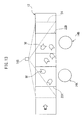
- FIG. 12 is a diagram schematically illustrating one example of article hold and transfer work
- FIG. 13 is a diagram for explaining one example of an article tracking process
- FIG. 14 is a diagram for explaining another example of an article tracking process
- FIG. 15 is a flowchart illustrating the processing performed by an article managing section in the image processing section
- FIG. 16 is a flowchart illustrating the processing performed by an article tracking section in the image processing section
- FIG. 17 is a flowchart illustrating the details of processing performed by the article tracking section
- FIG. 18 is a flowchart illustrating the details of processing performed by the article tracking section
- FIG. 19 is a flowchart illustrating the details of processing performed by the article tracking section
- FIG. 20 is a flowchart illustrating the processing performed by an information managing section in a first controlling section
- FIG. 21 is a flowchart illustrating the details of processing performed by the information managing section.
- FIG. 22 is a flowchart illustrating the details of processing performed by the information managing section.
- FIG. 1 shows an article transferring device 10 according to one embodiment.
- the article transferring device 10 includes a conveyor 12 configured to convey an article M, a robot 14 configured to hold and transfer the article M, an image capturing section 16 configured to capture an image of the article M, an image processing section 18 configured to control the image capturing section 16 and detect the article M based on the data of the image captured by the image capturing section 16 , and a robot controlling section 20 configured to control the robot 14 with use of information of the article M detected by the image processing section 18 .
- the conveyor 12 includes a known conveying member capable of supporting a plurality of articles M and conveying them in one direction (in the drawing, the direction indicated by arrow W), and a known driving mechanism for driving the conveying member in a continuous or intermissive manner.
- the plurality of articles M conveyed on the conveyor 12 may have various shapes, dimensions, appearances (colors), etc., or may have the same shape, dimension, appearance (color), etc.
- the articles M may be such articles as fruits or vegetables whose shapes tend to make the support of the articles M on the conveyor 12 unstable.
- the plurality of articles M are conveyed in a random arrangement on the conveyor 12 and enter a predetermined working space (the area where the articles M are held and picked up) 22 (indicated by semi-dashed lines) to be accessed by the robot 14 .
- the term “random arrangement” refers to an arrangement in which the articles M are not intended to be arranged in any orderly form but are arranged in a random manner such that the articles M take various positions and orientations in a two-dimensional space (e.g., in an image captured by the image capturing section 16 ) when the articles M are viewed from directly above.
- the conveyor 12 is not equipped with a sensor for detecting the amount of movement such as an encoder that can detect the position or speed of the conveying member or the driving mechanism.
- the robot 14 may include a mechanical section (not shown) suitably selected from among known mechanical sections (i.e., manipulators) of various types such as an articulated type, gantry type, and parallel link type, and a hand suitably selected from among known hands of various types such as a suction type and gripper type.
- the robot 14 is disposed in a predetermined position on one side of the conveyor 12 , and operates in such a manner that the mechanical section or hand holds and picks up the article M in the working space 22 of the robot 14 while tracking the article M being conveyed on the conveyor 12 , and transfers the article M to another place.
- the robot 14 is equipped with one mechanical section.
- the image capturing section 16 has a predetermined field of view 24 (indicated by dashed lines) which extends longitudinally in the conveying direction of the conveyor 12 to encompass a portion thereof and laterally across the entire width of the conveyor 12 .
- the working space 22 of the robot 14 is located within the field of view 24 .
- the image capturing section 16 obtains two-dimensional image data by imaging an image of the articles M and the conveyor 12 in the field of view 24 from directly above the conveyor 12 .
- the image capturing section 16 includes one camera (hereinafter, sometimes referred to as the camera 16 ).
- the camera 16 may be a digital camera, and the resolution and the image capturing range, for example, may be set as desired.
- the camera 16 may be switched between a mode that captures an image of a portion 24 a of the field of view 24 at the upstream end as viewed in the conveying direction of the conveyor and a mode that captures an image in the entire field of view 24 .
- the camera 16 is connected to the image processing section 18 via a camera cable 26 .
- the image processing section 18 applies appropriate image processing to the two-dimensional data that the image capturing section 16 obtained by imaging an image of the articles M and the conveyor 12 in the field of view 24 , and thereby detects the presence of each article M and obtains information representing the position (coordinate values) and orientation (rotation angle) of each article M in a predetermined two-dimensional coordinate system.
- the “position information” initial position information, shifted position information, etc.
- the “position information” usually includes information representing the position and orientation of the article M, but when the article M is circular in shape, for example, the “position information” may not include information representing the orientation of the article M.
- the image processing section 18 may also obtain information concerning the two-dimensional external shape, color, etc. of each article M (hereinafter referred to as the external appearance characteristic information).
- the position information of the article M obtained by the image processing section 18 may be displayed in the form of an image on a monitor not shown.
- the image processing section 18 is connected to the robot controlling section 20 via a communication cable 28 so that the position information of the article M detected from the two-dimensional data obtained by the image capturing section 16 may be transmitted as needed to the robot controlling section 20 .
- the image processing section 18 and the robot controlling section 20 may be incorporated into a single common control device, as will be described later.
- a two-dimensional conveyor coordinate system (stationary coordinate system) 30 may be defined for the conveyor 12 by taking its conveying direction as the X axis.
- the robot 14 may be operated in the conveyor coordinate system 30 in accordance with a command defined in the conveyor coordinate system 30 .
- the image processing section 18 may define the position information of the detected article M in the conveyor coordinate system 30 by performing the calibration of the image capturing section 16 in the conveyor coordinate system 30 .
- the robot controlling section 20 controls the robot 14 by using the position information of the article M detected by the image processing section 18 , and causes the robot 14 to perform a holding action that matches the type of the hand.
- the image processing section 18 includes an article detecting section 32 configured to execute image capturing and detection of a plurality of articles M that move according to a conveying motion of the conveyor 12 , with a first period T 1 allowing all of the plurality of articles M to be captured and detected, and obtain initial position information D 1 of each of all of the articles M, and an article tracking section 34 configured to execute image capturing and detection of the plurality of articles M that move according to the conveying motion of the conveyor 12 , with a second period T 2 shorter than the first period T 1 , and obtain shifted position information D 2 of each of the plurality of articles M iteratively with the second period T 2 , the shifted position information D 2 being based on the initial position information D 1 .
- the robot controlling section 20 is configured to control the robot 14 with use of the shifted position information D 2 , so as to make the robot 14 hold and transfer each of the plurality of articles M while following the conveying motion of the conveyor 12 .
- the initial position information D 1 and the shifted position information D 2 are each represented by the coordinate values and the rotation angle (or only by the coordinate values) in the conveyor coordinate system 30 .
- the article detecting section 32 has the function of initially recognizing and detecting (hereinafter sometimes described as “initially detecting”) each of the plurality of articles M in the field of view 24 of the image capturing section 16 as the articles M are conveyed on the conveyor 12 toward the working space 22 of the robot 14 .
- the article detecting section 32 is configured to initially detect each article M as the article M enters the upstream end portion 24 a of the field of view 24 of the image capturing section 16 .
- the first period T 1 is the period with which the image capturing section 16 can capture an entire image of each article M at least once in the upstream end portion 24 a of the field of view 24 .
- the first period T 1 required for the image of each particular article M being conveyed on the conveyor 12 to be captured once during the interval from the moment the entirety of the article M enters the upstream end portion 24 a to the moment a portion of the article M exits the upstream end portion 24 a is given as follows.
- the image of each article M can be captured and initially detected while the article M is located within the upstream end portion 24 a , and thus the initial position information D 1 of each of the articles M can be obtained.
- the article tracking section 34 has the function of subsequently recognizing and detecting (hereinafter sometimes described as “tracking”) each of the plurality of articles M in the field of view 24 of the image capturing section 16 after the articles M are initially detected by the article detecting section 32 .
- the article tracking section 34 is configured to track each article M in the entire field of view 24 of the image capturing section 16 .
- the second period T 2 is the period with which the image capturing section 16 can capture an entire image of each article M in the field of view 24 iteratively a number of times sufficient to track the article M without mistakenly detecting another article M.
- the image capturing of each article M by the image capturing section 16 and the detection by the article tracking section 34 should be completed within a period that the article M is conveyed on the conveyor 12 by a distance equal to one half of the minimum width of the article M.
- the image of each article M can be captured iteratively in the field of view 24 and tracked without mistaking it for another article M, and thus the shifted position information D 2 of each of the articles M can be obtained.
- the second period T 2 is set as short as the processing capability of the image processing section 18 can allow by disregarding the condition “one half of the minimum width of the article M”, the reliability of the shifted position information D 2 , and hence the accuracy with which the robot 14 operates to hold the article M while tracking its position, can be maximized.
- the image processing section 18 performs the image capturing and detection (i.e., tracking) with the second period T 2 by the article tracking section 34 concurrently with the image capturing and detection (i.e., initial detection) with the first period T 1 by the article detecting section 32 (i.e., it performs so-called multitasking).
- the article tracking section 34 continually and iteratively obtains the shifted position information D 2 representing the constantly changing position and orientation values (or only the position value) (i.e., the amount of change) of the article M by iteratively performing the image capturing and detection of the article M with the second period T 2 .
- the camera 16 constituting the image capturing section 16 performs the image capturing with the first period T 1 and the image capturing with the second period T 2 at appropriate timings and in appropriate order.
- the initial position information D 1 of each article M obtained by the article detecting section 32 is used for article tracking by the article tracking section 34 , and at the same time, the initial position information D 1 is assembled into a single packet (hereinafter referred to as a packet ⁇ ) and sent to the robot controlling section 20 together with other information necessary for causing the robot 14 to hold each article M.
- the information carried in the packet ⁇ includes a packet ID indicating that the information is the packet ⁇ , the initial position information D 1 obtained by the article detecting section 32 , the image capture time of the article corresponding to the initial position information D 1 , and an article ID as a sequence number indicating the article M.
- the packet ⁇ is created only once and sent to the robot controlling section 20 .
- the shifted position information D 2 of each article M iteratively obtained by the article tracking section 34 is also assembled into a single packet (hereinafter referred to as a packet ⁇ ) each time the information is obtained, and sent to the robot controlling section 20 together with other information necessary for causing the robot 14 to hold each article M.
- the information carried in the packet ⁇ includes a packet ID indicating that the information is the packet ⁇ , the shifted position information D 2 obtained by the article tracking section 34 , the image capture time of the article corresponding to the shifted position information D 2 , and an article ID as a sequence number indicating the article M.
- the packet ⁇ is created repeatedly and sent to the robot controlling section 20 .
- the robot controlling section 20 Based on the information of the packet ⁇ received from the image processing section 18 , the robot controlling section 20 creates article information for causing the robot 14 to hold each article M, and assembles the article information into a single packet (hereinafter referred to as a packet ⁇ ).
- the information carried in the packet ⁇ includes, in addition to the information of the packet ⁇ , the shifted position information D 2 and the article image capture time that are carried in the information of the packet ⁇ received from the image processing section 18 an arbitrary number of times up to that time, including the most recently received one.
- information concerning the moving speed of the article M (i.e., the conveying speed of the conveyor 12 ), which is obtained from the time interval over which the shifted position information D 2 and the article image capture time have been received the arbitrary number of times, may also be included in the packet ⁇ .
- the number of times that the packet ⁇ is to be received for the creation of the packet ⁇ may be set as desired by the user of the article transferring device 10 .
- the robot controlling section 20 deletes the information of the packet ⁇ concerning that article M.
- the robot controlling section 20 compares the information of the packet ⁇ constantly transmitted from the image processing section 18 with the currently held information of the packet ⁇ to recognize the presence of the article M going to enter the working space 22 of the robot 14 or currently traversing the working space 22 . Then, the robot controlling section 20 controls the robot 14 by using the shifted position information D 2 of the article M carried in the packet ⁇ corresponding to the article M whose presence has been recognized. Under the control of the robot controlling section 20 , the robot 14 holds and picks up the article M while following the conveying motion of the conveyor 12 , and transfers the article M from the conveyor 12 to a predetermined different place.
- the article tracking section 14 in the image processing section 18 obtains the shifted position information D 2 of the article M, and the robot controlling section 20 controls the robot 14 by using the shifted position information D 2 ; this eliminates the need to equip the conveyor 12 with a sensor such as an encoder for detecting the amount of movement, and the robot 14 can comprehend the current position of the article M conveyed by the conveyor 12 and hold the article while following the conveyor 12 .
- the system in which the robot holds each article while following the conveying motion of the conveyor and transfers the article to another place can be constructed even in a situation where it is difficult to equip the conveyor with a sensor such as an encoder for detecting the amount of movement.
- the article tracking section 34 is configured to obtain the shifted position information D 2 of each article M iteratively with the second period T 2 , if the position of the article M is displaced on the conveyor 12 after the article detecting section 32 has obtained the initial position information D 1 of the article M, the article tracking section 34 can update the shifted position information D 2 by tracking the position of the article M and, using the updated shifted position information D 2 , the robot 14 can comprehend the current position of the article M after the positional displacement and hold the article M.
- the above-described configuration of the article transferring device 10 may be described in the form of an article transferring method according to another aspect of the present invention.
- the article transferring method concerns a method for causing the robot 14 to hold each of a plurality of articles M conveyed on the conveyor 12 and to transfer the article M to another place, and includes the steps of: obtaining initial position information D 1 for each of the plurality of articles M being conveyed on the conveyor 12 by performing the image capturing and detection of the plurality of articles M with a first period T 1 allowing all of the plurality of articles M to be captured and detected; obtaining shifted position information D 2 relative to the initial position information D 1 for each of the plurality of articles M being conveyed on the conveyor 12 , iteratively with a second period T 2 shorter than the first period T 1 by performing the image capturing and detection of the plurality of articles M with the second period T 2 ; and based on the shifted position information D 2 , controlling the robot 14 so that the robot 14 transfers the articles M by holding each of the
- FIG. 2 shows a modified example of the article transferring device 10 .
- the image capturing section 16 includes a first camera 16 A and a second camera 16 B, configured to operate independently of each other.
- the field of view of the first camera 16 A encompasses the aforementioned upstream end portion 24 a of the field of view 24 as viewed in the conveying direction of the conveyor.
- the field of view of the second camera 16 B is the same as the field of view 24 .
- the article detecting section 32 is configured to make the first camera 16 A capture the image of the article M located within the field of view 24 a , and detect the article M based on the data of the image captured by the first camera 16 A.
- the article tracking section 34 is configured to make the second camera 16 B capture the image of the article M located within the field of view 24 , and detect the article M based on the data of the image captured by the second camera 16 B.
- Both the first camera 16 A and the second camera 16 B may be digital cameras, and the resolution and the image capturing range, for example, may be set as desired.
- the first and second cameras 16 A and 16 B are connected to the image processing section 18 via respective camera cables 26 . In this configuration, the image capturing performed by the first camera 16 A with the first period T 1 and the image capturing performed by the second camera 16 A with the second period T 2 may be executed concurrently.
- FIG. 3 shows another modified example of the article transferring device 10 .
- the robot 14 includes a first mechanical section 14 A and a second mechanical section 14 B, configured to operate independently of each other, and the robot controlling section 20 includes a first controlling section 20 A configured to control the first mechanical section 14 A and a second controlling section 20 B configured to control the second mechanical section 14 B.
- the first and second mechanical sections 14 A and 14 B each may have the configuration of any of various known mechanical sections (i.e., manipulators) and may be equipped with any of various known hands (not shown).
- the first mechanical section 14 A is disposed in a predetermined position on one side of the conveyor 12 , and operates in such a manner as to hold and pick up the article M in a working space 22 A while tracking the article M being conveyed on the conveyor 12 and to transfer the article M to another place.
- the second mechanical section 14 B is disposed in a predetermined position on one side of the conveyor 12 and on the downstream side of the first mechanical section 14 A as viewed in the conveying direction of the conveyor, and operates in such a manner as to hold and pick up the article M in a working space 22 B while tracking the article M being conveyed on the conveyor 12 and to transfer the article M to another place.
- the working spaces 22 A and 22 B are set so as not to overlap each other in order to prevent the first and second mechanical sections 14 A and 14 B from interfering with each other. Further, the working spaces 22 A and 22 B are both located within the field of view 24 of the image capturing section 16 .
- the first controlling section 20 A controls the first mechanical section 14 A based on the shifted position information D 2 so that the first mechanical section 14 A transfers the articles M by holding each of the plurality of articles M while following the conveying motion of the conveyor 12 .
- the second controlling section 20 B controls the second mechanical section 14 B based on the shifted position information D 2 so that the second mechanical section 14 B transfers the articles M by holding each of the plurality of articles M (other than the articles M picked up by the first mechanical section 14 A) while following the conveying motion of the conveyor 12 .
- the first and second controlling sections 20 A and 20 B are connected to each other via a communication cable 28 and are together connected to the image processing section 18 .
- the first and second controlling sections 20 A and 20 B may perform such control as to make the first and second mechanical sections 14 A and 14 B, respectively, hold predetermined numbers of articles M in accordance with a predetermined ratio of operation (i.e., work division ratio).
- a predetermined ratio of operation i.e., work division ratio
- FIG. 4 shows still another modified example of the article transferring device 10 .
- This modified example is a combination of the modified example of FIG. 2 and the modified example of FIG. 3 , and includes the first and second cameras 16 A and 16 B as the image capturing section 16 , the first and second mechanical sections 14 A and 14 B as the robot 14 , and the first and second controlling sections 20 A and 20 B as the robot controlling section 20 .
- the number of cameras constituting the image capturing section 16 and the number of mechanical sections constituting the robot 14 may be chosen suitably according to various factors such as the total number of articles M conveyed on the conveyor 12 , the conveying speed of the conveyor 12 , the time required for the robot 14 to transfer the articles M to another place, and the work accuracy required.
- three or more cameras, three or more robot mechanical sections, and three or more robot controlling sections may be provided.
- the cameras and robot mechanical sections disposed on the downstream side may be configured to do the work that the camera and robot mechanical section disposed on the upstream side did not do.
- FIG. 5 shows an article transferring device 40 according to another embodiment.
- the article transferring device 40 has substantially the same basic configuration as the above-described article transferring device 10 , except that the number of cameras constituting the image processing section 16 , the number of mechanical sections constituting the robot 14 , and the number of controlling sections constituting the robot controlling section 20 are different, and that a second conveyor is provided to which the robot 14 transfers the articles M.
- components corresponding to those in the article transferring device 10 are designated by like reference numerals, and further description of such component may be omitted.
- the configuration pertaining to the details of the article transferring device 10 and omitted from the earlier description may be described in detail below in connection with the configuration of the article transferring device 40 .
- the article transferring device 40 includes a conveyor 12 configured to convey an article M, a robot 14 configured to hold and transfer the article M, an image capturing section 16 configured to capture an image of the article M, an image processing section 18 configured to control the image capturing section 16 and detect the article M based on data of the image captured by the image capturing section 16 , and a robot controlling section 20 configured to control the robot 14 with use of information of the article M detected by the image processing section 18 .
- the article transferring device 40 further includes a second conveyor 42 (hereinafter referred to as a discharge conveyor) to which the robot 14 transfers the article M picked up from the conveyor 12 .
- the robot 14 includes a first mechanical section 14 A, a second mechanical section 14 B, and a third mechanical section 14 C, configured to operate independently of one another.
- the first mechanical section 14 A is disposed in a predetermined position on one side of the conveyor 12 , and operates in such a manner as to hold and pick up the article M in a working space 22 A while tracking the article M being conveyed on the conveyor 12 and to transfer the article M to the discharge conveyor 42 .
- the second mechanical section 14 B is disposed in a predetermined position on one side of the conveyor 12 and on the downstream side of the first mechanical section 14 A as viewed in the conveying direction of the conveyor, and operates in such a manner as to hold and pick up the article M in a working space 22 B while tracking the article M being conveyed on the conveyor 12 and to transfer the article M to the exit conveyor 42 .
- the third mechanical section 14 C is disposed in a predetermined position on one side of the conveyor 12 and on the downstream side of the second mechanical section 14 B as viewed in the conveying direction of the conveyor, and operates in such a manner as to hold and pick up the article M in a working space 22 C while tracking the article M being conveyed on the conveyor 12 and to transfer the article M to the discharge conveyor 42 .
- the working spaces 22 A, 22 B and 22 C are set so as not to overlap each other in order to prevent the adjacent mechanical sections 14 A, 14 B and 14 C from interfering with each other.
- the first to third mechanical sections 14 A, 14 B and 14 C may have substantially the same hardware configuration.
- the image capturing section 16 includes a first camera 16 A, a second camera 16 B and a third camera 16 C, configured to operate independently of one another.
- the first camera 16 A has a predetermined field of view 44 (indicated by dashed lines) which extends longitudinally in the conveying direction of the conveyor 12 to encompass a portion thereof and laterally across the entire width of the conveyor 12 .
- the field of view 44 is set in a position corresponding to the earlier described upstream end portion 24 a of the field of view 24 as viewed in the conveying direction of the conveyor (see FIG. 1 ) but shifted upstream by a prescribed distance as viewed in the conveying direction of the conveyor.
- the field of view of the second camera 16 B is the same as the field of view 24 .
- the field of view 44 of the first camera 16 A and the field of view 24 of the second camera 16 B partially overlap each other.
- the third camera 16 C has a predetermined field of view 46 (indicated by dashed lines) which extends longitudinally in the conveying direction of the conveyor 12 to encompass a portion thereof and laterally across the entire width of the conveyor 12 .
- the field of view 46 is set so as to extend further downstream from the downstream end of the field of view 24 as viewed in the conveying direction of the conveyor.
- the field of view 46 of the third camera 16 C and the field of view 24 of the second camera 16 B partially overlap each other.
- the working spaces 22 A and 22 B of the first and second mechanical sections 14 A and 14 B are located within the field of view 24 of the second camera 16 B.
- the working space 22 C of the third camera 14 C is located within the field of view 46 of the third camera 16 C.
- the first to third cameras 16 A, 16 B and 16 C are connected to the image processing section 18 via respective camera cables 26 .
- the first to third cameras 16 A, 16 B and 16 C may have substantially the same hardware configuration.
- the robot controlling section 20 includes a first controlling section 20 A configured to control the first mechanical section 14 A, a second controlling section 20 B configured to control the second mechanical section 14 B, and a third controlling section 20 C configured to control the third mechanical section 14 C.
- the first controlling section 20 A controls the first mechanical section 14 A based on the shifted position information D 2 so that the first mechanical section 14 A transfers the articles M by holding each of the plurality of articles M while following the conveying motion of the conveyor 12 .
- the second controlling section 20 B controls the second mechanical section 14 B based on the shifted position information D 2 so that the second mechanical section 14 B transfers the articles M by holding each of the plurality of articles M (other than the articles M picked up by the first mechanical section 14 A) while following the conveying motion of the conveyor 12 .
- the third controlling section 20 C controls the third mechanical section 14 C based on additional shifted position information D 3 (to be described later) so that the third mechanical section 14 C transfers the articles M by holding each of the plurality of articles M (other than the articles M picked up by the second mechanical section 14 B) while following the conveying motion of the conveyor 12 .
- the first to third controlling sections 20 A, 20 B and 20 C are connected to one another via a communication cable 28 and a network hub 48 and are together connected to the image processing section 18 .
- the first to third controlling sections 20 A, 20 B and 20 C may have substantially the same hardware configuration.
- the image processing section 18 includes an article detecting section 32 configured to make the first camera 16 A capture the image of the article M located within the field of view 44 and detect (or initially detect) the article M based on the data of the image captured by the first camera 16 A, an article tracking section 34 configured to make the second camera 16 B capture the image of the article M located within the field of view 24 and detect (or track) the article M based on the data of the image captured by the second camera 16 B, and an auxiliary tracking section 50 configured to make the third camera 16 C capture the image of the article M located within the field of view 46 and detect (or track) the article M based on the data of the image captured by the third camera 16 C.
- an article detecting section 32 configured to make the first camera 16 A capture the image of the article M located within the field of view 44 and detect (or initially detect) the article M based on the data of the image captured by the first camera 16 A
- an article tracking section 34 configured to make the second camera 16 B capture the image of the article M located within the field of view 24 and detect (or
- the auxiliary tracking section 50 is configured to execute image capturing and detection of a plurality of articles M that move according to the conveying motion of the conveyor 12 , with a third period T 3 shorter than the first period T 1 , and obtain additional shifted position information D 3 of each of the plurality of articles M iteratively with the third period T 3 , the additional shifted position information being based on the shifted position information D 2 .
- the auxiliary tracking section 50 has the function of continuing to track each of the plurality of articles M in the field of view 46 of the third camera 16 C after the articles M are tracked in the field of view 24 of the second camera 16 B by the article tracking section 34 .
- the third camera 16 C and the auxiliary tracking section 50 are provided in order to cause the third mechanical section 14 C to pick up those articles M that the first and second mechanical sections 14 A and 14 B did not pickup in their working spaces 22 A and 22 B among the articles M that the article tracking section 34 tracked in the field of view 24 .
- the third period T 3 may be set in accordance with the same condition as the second period T 2 , and may be set the same as the second period T 2 .
- the image processing section 18 performs the image capturing and detection (i.e., initial detection) with the first period T 1 by the article detecting section 32 , the image capturing and detection (i.e., tracking) with the second period T 2 by the article tracking section 34 , and the image capturing and detection (i.e., tracking) with the third period T 3 by the auxiliary tracking section 50 in concurrent fashion.
- the first to third cameras 16 A, 16 B and 16 C may perform the image capturing with the first to third periods T 1 , T 2 and T 3 , respectively, in concurrent fashion.
- the auxiliary tracking section 50 continually and iteratively obtains the additional shifted position information D 3 representing the constantly changing position and orientation values (or only the position value) (i.e., the amount of change) of the article M by iteratively performing the image capturing and detection of the article M with the third period T 3 .
- the initial position information D 1 of each article M obtained by the article detecting section 32 is used for article tracking by the article tracking section 34 , and at the same time, the initial position information D 1 assembled in the form of the earlier described packet ⁇ is sent only to the first controlling section 20 A.
- the packet ⁇ carries, in addition to the earlier described information, a camera ID indicating the first camera 16 A that obtained the image data based on which the initial position information D 1 was created.
- the shifted position information D 2 of each article M iteratively obtained by the article tracking section 34 and the additional shifted position information D 3 of each article M iteratively obtained by the auxiliary tracking section 50 are each assembled in the form of the earlier described packet ⁇ each time the information is obtained, and are sent to all of the first to third controlling sections 20 A, 20 B and 20 C.
- the packet ⁇ carries, in addition to the earlier described information, a camera ID indicating the second or third camera 16 B or 16 C that obtained the image data based on which the shifted position information D 2 or the additional shifted position information D 3 was created.
- the first controlling section 20 A Based on the information of the packet ⁇ received from the image processing section 18 , the first controlling section 20 A creates article information for causing the first to third mechanical sections 14 A, 14 B and 14 C to hold articles M, and assembles the article information in the form of the earlier described packet ⁇ .
- the information carried in the packet ⁇ includes, in addition to the information of the packet ⁇ , the shifted position information D 2 or additional shifted position information D 3 and the article image capture time that are carried in the information of the packet ⁇ received from the image processing section 18 an arbitrary number of times up to that time, including the most recently received one.
- the first controlling section 20 A deletes the information of the packet ⁇ concerning that article M; on the other hand, for any article M not removed from the conveyor 12 by the first mechanical section 14 A, the first controlling section 20 A transmits the information of the packet ⁇ to the second controlling section 20 B.
- the second controlling section 20 B that received the information of the packet ⁇ from the first controlling section 20 A deletes the information of the packet ⁇ when the article M is picked up by the second mechanical section 14 B and removed from the conveyor 12 ; on the other hand, for any article M not removed from the conveyor 12 by the second mechanical section 14 B, the second controlling section 20 B transmits the information of the packet ⁇ to the third controlling section 20 C.
- the first to third controlling sections 20 A, 20 B and 20 C each compare the information of the packet ⁇ constantly transmitted from the image processing section 18 with the currently held information of the packet ⁇ to recognize the presence of the article M going to enter the working space 22 A, 223 or 22 C of the corresponding one of the first to third mechanical sections 14 A, 143 and 14 C or currently traversing the working space 22 A, 223 or 22 C, respectively. Then, the first and second controlling sections 20 A and 203 each control the first or second mechanical section 14 A or 14 B, respectively, by using the shifted position information D 2 of the article M carried in the packet ⁇ corresponding to the article M whose presence has been recognized.
- the third controlling section 20 C controls the third mechanical section 14 C by using the additional shifted position information D 3 of the article M carried in the packet ⁇ corresponding to the article M whose presence has been recognized.
- the first to third mechanical sections 14 A, 14 B and 14 C each hold and pick up the article M while following the conveying motion of the conveyor 12 , and transfers the article M from the conveyor 12 to the discharge conveyor 42 .
- the discharge conveyor 42 is disposed side by side with the conveyor 12 in substantially parallel relationship with each other in a position where the first to third mechanical sections 14 A, 14 B and 14 C may perform the task of transferring the articles M.
- the discharge conveyor 42 includes a known conveying member capable of conveying a plurality of articles M in one direction (in the drawing, the direction indicated by arrow W) by holding the articles M thereon, and a known driving mechanism for driving the conveying member in a continuous or intermissive manner.
- the discharge conveyor 42 is equipped with an encoder 52 for detecting the amount of movement of the conveying member. The amount of movement detected by the encoder 52 is sent to the first controlling section 20 A, and is shared among the first to third controlling sections 20 A, 20 B and 20 C interconnected via a communication network.
- a plurality of trays 54 each capable of holding a predetermined number of articles M in a predetermined arrangement are conveyed on the discharge conveyor 42 .
- the discharge conveyor 42 is equipped with a phototube sensor 56 for detecting the arrival of each tray 54 at a prescribed position.
- the first controlling section 20 A Upon receiving a detection signal of one tray 54 from the phototube sensor 56 , the first controlling section 20 A reads the amount of movement of the discharge conveyor 42 from the encoder 52 and stores the readout value as the initial value; then, by comparing the constantly updated detection value of the encoder 52 with the stored initial value, the current position of the tray 54 can be determined.
- Each tray 54 is capable of holding a plurality of articles M in accordance with a predetermined arrangement pattern 58 .
- FIG. 6A shows one example of the arrangement pattern 58 of the articles M on the tray 54 .
- the arrangement pattern 58 includes four pattern elements P 1 , P 2 , P 3 and P 4 , each representing the position of one article M.
- an arrangement form 59 FIG. 6B ) is presented which defines the pattern elements P 1 , P 2 , P 3 and P 4 by their coordinate values (X, Y) and relative rotation angles ⁇ in a coordinate system 57 that has its origin at upper right corner of the tray 54 in a two-dimensional image.
- the coordinate values of P 1 , P 2 , P 3 and P 4 are (X1, Y1), (X1, Y2), (X2, Y1) and (X2, Y2), respectively, and the rotation angles of P 1 , P 2 , P 3 and P 4 are 0°, ⁇ 90°, 90° and 180°, respectively.
- the first to third controlling sections 20 A, 20 B and 20 C control the first to third mechanical sections 14 A, 14 B and 14 C, respectively, so that the articles M are placed one by one on the tray 54 in accordance with the arrangement pattern 58 having the above-described pattern elements P 1 , P 2 , P 3 and P 4 .
- FIG. 6A four arrowhead-shaped articles M are shown arranged on the tray in accordance with the arrangement pattern 58 .
- the pattern elements P 1 , P 2 , P 3 and P 4 are each indicated by a mark “+” to facilitate understanding, but the pattern elements P 1 , P 2 , P 3 and P 4 themselves need not have shapes.
- the four articles M are shown arranged in the arrangement pattern 58 by registering the geometrical center points of the two-dimensional outer shapes of the respective articles M with the pattern elements P 1 , P 2 , P 3 and P 4 , respectively, but alternatively, some other common points suitably defined on the respective articles M may be registered with the respective pattern elements P 1 , P 2 , P 3 and P 4 .
- FIG. 7 shows one example of the hardware configuration of each of the first to third controlling sections 20 A, 20 B and 20 C or the robot controlling section 20 ( FIG. 1 ).
- Each of the first to third controlling sections 20 A, 20 B and 20 C or the robot controlling section 20 is equipped with a CPU 60 including a microprocessor.
- a ROM 62 , a RAM 64 , an SRAM 66 , a digital signal processor (DSP) data memory 68 , and a digital signal processor (DSP) 70 are connected to the CPU 60 via a bus 71 .
- the ROM 62 A stores a program for controlling the entire system, and the RAM 64 temporarily stores data to be processed by the CPU 60 .
- the SRAM 66 stores an operating program and setup data for each of the first to third controlling sections 20 A, 20 B and 20 C or the robot 14 .
- the DSP 70 is a processor for processing signals output from the encoder 52 , and the DSP data memory 68 stores setup parameters as well as data processed by the DSP 70 .
- the DSP 70 has the function of detecting an output from the encoder 52 at a given point in time in accordance with an instruction from the CPU 60 and writing the result to a designated area in the DSP data memory 68 .
- Each of the first to third controlling sections 20 A, 20 B and 20 C or the robot controlling section 20 includes an axis controlling section 72 for controlling the corresponding one of the mechanical sections 14 A, 14 B and 14 C or the robot 14 .
- the axis controlling section 72 is connected to the corresponding one of the mechanical sections 14 A, 14 B and 14 C or the robot 14 via a servo circuit 74 .
- each of the first to third controlling sections 20 A, 20 B and 20 C or the robot controlling section 20 can control the corresponding one of the mechanical sections 14 A, 14 B and 14 C or the robot 14 .
- Each of the first to third controlling sections 20 A, 20 B and 20 C or the robot controlling section 20 further includes a communication interface 76 and an I/O interface 78 , and can communicate, via these interfaces, with the other two of the controlling sections 20 A, 20 B and 20 C and with the image processing section 18 and peripheral devices such as the phototube sensor 56 .
- FIG. 8 shows one example of the hardware configuration of the image processing section 18 .
- the image processing section 18 is equipped with a CPU 80 including a microprocessor.
- a ROM 82 a RAM 84 , a monitor interface 88 for connecting to an external monitor 86 , and a camera interface for connecting to each of the first to third cameras 16 A, 16 B and 16 C or the image capturing section 16 ( FIG. 1 ) are connected to the CPU 80 via a bus 92 .
- Images captured by each of the first to third cameras 16 A, 16 B and 16 C or the image capturing section 16 are stored into the RAM 84 via the camera interface 90 .
- the camera interface 90 can control each of the cameras 16 A, 16 B and 16 C independently of the others, so that an image capturing operation can always be performed with designated timing regardless of the image imaging conditions of the cameras 16 A, 16 B and 16 C.
- the data stored in the RAM 84 is analyzed by the CPU 80 and is obtained by the image processing section 18 as the information representing the position and orientation of each article M (initial position information D 1 , shifted position information D 2 , and additional shifted position information D 3 ).
- the image processing section 18 can also obtain external appearance characteristic information such as the shape and color of the article M from the image data stored in the RAM 84 .
- the ROM 82 stores an analysis program and various setup information for the image processing section 18 .
- the CPU 80 supports so-called multi-core, multi-threaded operations, and can concurrently execute the analyses of the image data captured by the first to third cameras 16 A, 16 B and 16 C.
- the image processing section 18 further includes a communication interface 94 and an I/O interface 96 , and can communicate, via these interfaces, with each of the controlling sections 20 A, 20 B and 20 C and peripheral devices.
- each of the controlling sections 20 A, 20 B and 20 C or the robot controlling section 20 and the image processing section 18 may be incorporated into a single common control device 98 .
- the CPU 80 in the image processing section 18 is connected to the CPU 60 in each of the controlling sections 20 A, 20 B and 20 C or the robot controlling section 20 via a bus 100 in the control device 98 .
- the CPU 80 in the image processing section 18 can access the SRAM 66 to store various setup information or access the DSP data memory 68 to read information of the encoder 52 via the CPU 60 in each of the controlling sections 20 A, 20 B and 20 C or the robot controlling section 20 .
- the CPU 80 in the image processing section 18 can be connected as needed to the communication interface 76 and the I/O interface 78 via the CPU 60 in each of the controlling sections 20 A, 20 B and 20 C or the robot controlling section 20 .
- the communication interface 94 and the I/O interface 96 may be omitted.
- the CPU 60 , ROM 62 and RAM 64 in each of the controlling sections 20 A, 20 B and 20 C or the robot controlling section 20 may be used to substitute for the CPU 80 , ROM 82 and RAM 84 in the image processing section 18 .
- FIG. 10 illustrates the control device 98 having such a simplified hardware configuration.
- FIG. 11 shows in functional block form the various sections that are incorporated in the image processing section 18 and the first to third controlling sections 20 A, 20 B and 20 C of the article transferring device 40 to handle information relating to the articles M and information relating to the pickup and transfer work for the articles M.
- arrows indicate the flow of the information relating to the articles M and the flow of the information relating to the pickup and transfer work for the articles M.
- the first to third controlling sections 20 A, 20 B and 20 C include work content setting sections 102 A, 102 B and 102 C, respectively.
- the work content setting sections 102 A, 102 B and 102 C set the work content relating to the article pickup and transfer work, such as the work division ratio among the first to third mechanical sections 14 A, 14 B and 14 C ( FIG. 5 ), the arrangement pattern 58 of the articles M on the tray 54 , and the working spaces 22 A, 22 B and 22 C ( FIG. 5 ) on the conveyor 12 .
- the work content set by any one of the work content setting sections 102 A, 102 B and 102 C can be transmitted to any other one of the work content setting sections 102 A, 102 B and 102 C in the controlling sections 20 A, 20 B and 200 via a communication network so that the work content can be shared among the work content setting sections 102 A, 102 B and 102 C in the controlling sections 20 A, 20 B and 20 C.
- the work division ratio among the first to third mechanical sections 14 A, 14 B and 14 C will be described below.
- the articles M 1 , M 2 , M 3 and M 4 arranged in this order from the top as shown in FIG. 12 are conveyed on the conveyor 12 and supplied to the working spaces 22 A, 22 B and 22 C ( FIG. 5 ) and are picked up by the first to third mechanical sections 14 A, 14 B and 14 C ( FIG. 5 ) and transferred onto the tray 54 on the discharge conveyor 42 so that the articles M 1 , M 2 , M 3 and M 4 will be arranged in the previously described arrangement pattern 58 .
- One example of the article pickup and transfer work performed by the respective mechanical sections 14 A, 14 B and 14 C will be described below for the case where the work division ratio among the first to third mechanical sections 14 A, 14 B and 14 C is set to 1:1:1 in the above situation.
- the first mechanical section 14 A disposed in the most upstream position picks up the first supplied article M 1 from the conveyor 12 and places it onto the pattern element P 1 on the tray 54 in accordance with the arrangement pattern 58 .
- the second mechanical section 14 B picks up the article M 2 , the first of the two articles that the first mechanical section 14 A let pass by, from the conveyor 12 and places it onto the pattern element P 3 on the tray 54 in accordance with the arrangement pattern 58 .
- the third mechanical section 14 C picks up the remaining article M 3 from the conveyor 12 and places it onto the pattern element P 4 on the tray 54 in accordance with the arrangement pattern 58 .
- the article pickup and transfer work division ratio among the first to third mechanical sections 14 A, 14 B and 14 C is 2:1:1.
- the second and third mechanical sections 14 B and 14 C each pick up one of the articles that the first mechanical section 14 A let pass by, and transfer it onto that next tray 54 .
- the article pickup and transfer work division ratio among the first to third mechanical sections 14 A, 14 B and 14 C is 3:2:2.
- the first to third mechanical sections 14 A, 14 B and 14 C pick up the plurality of articles M from the conveyor 12 in the order in which the articles M are supplied, and transfer them onto the tray 54 in the order of the pattern elements P 1 to P 4 in the arrangement pattern 58 . Further, in order to achieve the division ratio closest to the work division ratio R, the first to third mechanical sections 14 A, 14 B and 14 C in this order determine whether the respective articles M are to be picked up or not.
- a desired work rule may be determined in advance by the user of the article transferring device 40 and may be stored in advance in the SRAMs 66 in the first to third controlling sections 20 A, 20 B and 20 C.
- the first controlling section 20 A includes a tray detecting section 104 , an information managing section 106 A, and a work executing section 108 A.
- the second controlling section 20 B includes an information managing section 106 E and a work executing section 108 B.
- the third controlling section 20 C includes an information managing section 106 C and a work executing section 108 C.
- the tray detecting section 104 detects the tray 54 ( FIG. 5 ) based on an input of a tray detection signal from the phototube sensor 56 ( FIG. 5 ), reads the detection value from the encoder 52 ( FIG. 5 ) of the discharge conveyor 42 ( FIG. 5 ) at the instant of detection, and transfers the detection value to the information managing section 106 A. If the position of the phototube sensor 56 and the traveling direction of the discharge conveyor 42 are associated in advance by the work content setting section 102 A with a robot coordinate system of the first mechanical section 14 A ( FIG. 5 ) (in the embodiment of FIG.
- the information managing section 106 A can obtain the position of the detected tray 54 and the coordinate values and relative rotation angles of the pattern elements P 1 to P 4 of the arrangement pattern 58 ( FIG. 12 ) in the robot coordinate system by using the detection value of the encoder 52 transferred upon detection of the tray from the tray detecting section 104 .
- Information concerning the coordinate values and relative rotation angles of the pattern elements P 1 to P 4 is temporarily held in the information managing section 106 A, but information relating to any one of the pattern elements P 1 to P 4 on which the first mechanical section 14 A did not place the article M is transferred as the information of the packet ⁇ to the information managing section 106 B in the second controlling section 20 B via the communication network.
- the image processing section 18 includes a condition setting section 110 and an article managing section 112 in addition to the article detecting section 32 , the article tracking section 34 , and the auxiliary tracking section 50 .
- the condition setting section 110 sets various conditions for detecting or tracking each article M, such as a teaching model image for the article M to be detected or tracked, parameters (coordinate values, rotation angles, dimensions, etc.) used for article detection, and calibration data for the first to third cameras 16 A, 16 B and 16 C ( FIG. 5 ).
- the condition setting section 110 can obtain information concerning the working spaces 22 A, 22 B and 22 C of the first to third mechanical sections 14 A, 14 B and 14 C ( FIG. 5 ) by communicating with the work content setting section 102 A in the first controlling section 20 A.
- the article detecting section 32 starts the initial detection of the article M by using the first camera 16 A when the conveyor 12 has moved for a predetermined period of time from the start of the work.
- the initial detection of the article M may be started when an external sensor such as a phototube sensor (not shown) has detected the movement of the conveyor 12 for a predetermined period of time.
- the article detecting section 32 can obtain the initial position information D 1 ( FIG.
- any of various known detection algorithms such as a method that detects the article M by searching for an image that matches a preregistered model image from among the images captured by the first camera 16 A (e.g., a normalized correlation method), a method that extracts the contour of the article M from the preregistered model image and, based on the information of the detected contour, obtains the position information of the article M in the image captured by the first camera 16 A (e.g., a generalized Hough transform method), or a method that obtains the position information of the article M by detecting from the image captured by the first camera 16 A a region having an area size that falls within a preregistered range (e.g., a blob detection method).
- a method that detects the article M by searching for an image that matches a preregistered model image from among the images captured by the first camera 16 A e.g., a normalized correlation method
- the article detecting section 32 Upon succeeding in the initial detection of the article M, the article detecting section 32 sets a flag (hereinafter referred to as a new detection flag) indicating that the detected article M is a newly detected one, and transfers the new detection flag to the article managing section 112 together with such information as the initial position information D 1 of the detected article M, the camera ID of the first camera 16 A used to capture the image of the article M, the image capture time of the article M, and the new article ID of the article M.
- the article managing section 112 transfers these pieces of information received from the article detecting section 32 on to the article tracking section 34 , while also transferring the information as the information of the packet ⁇ to the information managing section 106 A in the first controlling section 20 A.
- the article tracking section 34 starts the tracking of the article M by using the second camera 16 B when the article M corresponding to the initial position information D 1 received from the article managing section 112 has entered the field of view 24 ( FIG. 5 ) of the second camera 16 B.
- the article tracking section 34 tracks the article M by taking the initial position information D 1 of the article M received from the article managing section 112 as the initial value.
- the unique article ID assigned to the article M at the time of the initial detection by the article detecting section 32 is retained throughout the process performed by the article tracking section 34 .
- the tracking of the article M by the article tracking section 34 is performed in a successive manner by comparing the various pieces of information (position information and external appearance characteristic information) obtained at the time of the current image capture with the various pieces of information obtained at the time of the previous or an earlier image capture, based on the image data that the second camera 16 B generated by capturing the image of the article M iteratively with the extremely short second period T 2 .
- particle filtering also called a particle filter or sequential Monte Carlo method
- particle filtering that can estimate a nonlinear, non-Gaussian system, for example, may be used (for particle filtering, refer, for example, to “Journal of the Robotics Society of Japan, Vol. 29, No. 5, pp. 427-430, 2011”).
- the article tracking section 34 transfers information, such as the most recent shifted position information D 2 ( FIG. 5 ) of the article M obtained during the tracking, the camera ID of the second camera 16 B used to capture the image of the article M, the image capture time of the article M, and the article ID of the article M, to the article managing section 112 in a successive manner.
- the article managing section 112 transfers these pieces of information received from the article tracking section 34 on to the auxiliary tracking section 50 , while also transferring the information as the information of the packet ⁇ to the information managing sections 106 A, 106 B and 106 C in the first to third controlling sections 20 A, 20 B and 20 C.
- the auxiliary tracking section 50 starts the tracking of the article M by using the third camera 16 C when the article M corresponding to the shifted position information D 2 received from the article managing section 112 has entered the field of view 46 ( FIG. 5 ) of the third camera 16 C.
- the auxiliary tracking section 50 tracks the article M by taking as the initial value the shifted position information D 2 received from the article managing section 112 when the article M has entered the field of view 46 ( FIG. 5 ) of the third camera 16 C.
- the tracking process performed by the auxiliary tracking section 50 is substantially the same as the tracking process performed by the article tracking section 34 described above, except that the third camera 16 C is used to capture the image of the article M.
- the auxiliary tracking section 50 transfers information, such as the most recent additional shifted position information D 3 ( FIG.
- the article managing section 112 that received these pieces of information received from the auxiliary tracking section 50 transfers the information as the information of the packet ⁇ to the information managing sections 106 A, 106 B and 106 C in the first to third controlling sections 20 A, 20 B and 20 C.
- the article tracking section 34 and the auxiliary tracking section 50 may use as the detection algorithm for article tracking any one of various known pattern recognition algorithms such as the normalized correlation method, the generalized Hough transform method, or the blob detection method as in the article detecting section 32 .
- the normalized correlation method, the generalized Hough transform method, the blob detection method, etc. usually provide higher detection accuracy than the particle filter method, but the processing speed is slower.
- an increase in the time required for tracking can be prevented by narrowing the range of the detection parameter (coordinate values, rotation angle, dimensions, area size, etc.) or the detection search range in the two-dimensional image captured by the second or third camera 16 B or 16 C, compared with the range used by the article detecting section 32 for the initial detection.
- the detection parameter coordinate values, rotation angle, dimensions, area size, etc.
- the article detecting section 32 obtains the initial position information D 1 of the article M by performing the initial detection, for example, within the range of ⁇ 180 degrees because, at this time, the position and orientation of the article M is unknown;
- the article tracking section 34 and the auxiliary tracking section 50 use the normalized correlation method, the generalized Hough transform method, the blob detection method, or the like, the article tracking section 34 and the auxiliary tracking section 50 can perform the article detection (tracking) by narrowing the range down to within ⁇ 5 degrees on the assumption that the position and orientation does not change substantially from the result of the initial detection or the previous tracking.
- the tracking process performed by the auxiliary tracking section 50 ( FIG. 11 ) in the image processing section 18 is substantially the same as the tracking process by the article tracking section 34 described below.
- a plurality of articles M arranged in a random manner are conveyed on the conveyor 12 ; here, when any one of the articles M is located within the working space 22 A, the first mechanical section 14 A holds and picks up the article M, and when another one of the articles M is located within the working space 22 B, the second mechanical section 14 B holds and picks up the article M.
- the second camera 16 B captures the images of all the articles located within the field of view 24 iteratively with the second period T 2 .
- the computational burden of the article tracking section 34 performing the tracking process is largely determined by the size of the image data captured by the second camera 16 B, the type of the algorithm used for the article detection, the number of articles M to be detected, and the range of the article detection parameter. Assuming that the number of articles M to be detected and the algorithm used are respectively the same, the computational burden of the article tracking section 34 can be reduced by reducing the resolution of the image data or by narrowing the range of the detection parameter.
- the resolution, i.e., the size, of the image data captured by the second camera 16 B affects the accuracy with which the article tracking section 34 detects each article M, which in turn affects the accuracy of the article holding operation performed by the first and second mechanical sections 14 A and 14 B.
- the detection accuracy has no relevance to the holding operation performed by the first and second mechanical sections 14 A and 14 B.
- the condition setting section 110 in the image processing section 18 communicates with the work content setting section 102 A in the first controlling section 20 A and obtains information about the locations on the conveyor 12 of the working spaces 22 A and 22 B of the first and second mechanical sections 14 A and 14 B as position information in the conveyor coordinate system 30 .
- the article tracking section 34 may be configured to detect an article M located inside the working space 22 A, 22 B with use of image data of a first resolution corresponding to a required detection accuracy, and to detect an article M located outside the working space 22 A, 22 B with use of image data of a second resolution lower than the first resolution, based on the information of the working spaces 22 A and 22 B obtained by the condition setting section 110 .
- This configuration serves to reduce the computational burden of the article tracking section 34 , compared with the configuration in which all the articles located within the field of view 24 of the second camera 16 B are detected using the image data of the first resolution.
- the computational burden of the tracking process can be reduced using a similar technique.
- the article tracking section 34 is configured to be able to obtain the first-resolution (or high-resolution) image data captured by imaging the inside of the working spaces 22 A and 22 B of the first and second mechanical sections 14 A and 14 B ( FIG. 13 ) and the second-resolution (or low-resolution) image data captured by imaging the outside of the working spaces 22 A and 22 B.
- the auxiliary tracking section 50 is configured to be able to obtain the first-resolution image data captured by imaging the inside of the working space 22 C of the third mechanical section 14 C ( FIG. 5 ) and the second-resolution image data captured by imaging the outside of the working space 22 C.
- the second or third camera 16 B or 16 C may be equipped with a switching mechanism 114 ( FIG. 4 ) configured to switch a resolution between the first resolution and the second resolution.
- the second or third camera 16 B or 16 C images the entire field of view 24 or 46 with the first resolution as well as the second resolution so that the article tracking section 34 or the auxiliary tracking section 50 can detect the articles M located inside the working spaces 22 A and 22 B or the working space 22 C by using the first-resolution image data and detect the articles M located outside the working spaces 22 A and 22 B or the working space 22 C by using the second-resolution image data.
- the second or third camera 16 B or 16 C images the field of view 24 or 46 with a prescribed resolution; in this case, the article tracking section 34 or the auxiliary tracking section 50 can obtain the second-resolution image data in addition to the first-resolution image data by reducing the resolution of the image data using a known image processing technique.
- the article tracking section 34 may be configured to be able to select and use one or the other of two detection algorithms, of which the first detection algorithm ensures a first processing speed and first accuracy and the second detection algorithm ensures a second processing speed higher than the first processing speed and/or a second accuracy lower than the first accuracy.
- the article tracking section 34 may be configured to detect an article M located inside the working spaces 22 A and 22 B of the first and second mechanical sections 14 A and 14 B with use of the first detection algorithm, and to detect an article M located outside the working spaces 22 A and 22 B with use of the second detection algorithm.
- the normalized correlation method, the generalized Hough transform method, the blob detection method, or the like may be employed as the first detection algorithm.
- the particle filter method may be employed as the second algorithm.
- the auxiliary tracking section 50 may be configured in a similar way.
- the article tracking section 34 detects the articles M in the entire field of view 24 by using the second detection algorithm (or the particle filter method). In the tracking process performed by the article tracking section 34 , this article detection is performed as a preparatory step to the step of obtaining the accurate shifted position information D 2 of each article M.
- the article tracking section 34 detects any article M at least a portion of which is located inside one or the other of the first and second working spaces 22 A and 22 B by using the first detection algorithm (or the normalized correlation method, generalized Hough transform method or blob detection method). In the tracking process performed by the article tracking section 34 , this article detection is performed as a step complementary to the step of obtaining the accurate shifted position information D 2 of each article M.
- the first detection algorithm or the normalized correlation method, generalized Hough transform method or blob detection method
- the second detection algorithm or the particle filter method
- the article tracking section 34 can perform the tracking process by using detection algorithms achieving different processing speeds and different accuracies.
- the detection using the first (high resolution) detection algorithm can be performed only on a prescribed number of articles M, as counted from the downstream side in the conveying direction, that are highly likely to be picked up by the first or second mechanical section 14 A or 14 B.
- the article tracking section 34 may be configured so as to detect only two articles, as counted from the downstream side, with high accuracy in each cycle of the article tracking process which is performed repeatedly. According to this configuration, the computational burden of the article tracking section 34 can be alleviated by reducing the number of articles M to be detected.
- the article transferring device 10 of FIG. 1 may be configured in a similar way to that described above.
- the article tracking section 34 may be configured to obtain a first-resolution image data captured by imaging the inside of the working space 22 where the robot 14 performs the article pickup work and a second-resolution image data captured by imaging the outside of the working space 22 , the second resolution of the second-resolution image data being lower than the first resolution of the first-resolution image data; and also be configured to detect an article M located inside the working space 22 with use of the first-resolution image data and an article M located outside the working space 22 with use of the second-resolution image data.
- the article tracking section 34 may be configured to select either a first detection algorithm that ensures a first processing speed and a first accuracy or a second detection algorithm that ensures a second processing speed and/or a second accuracy, the second processing speed being higher than the first processing speed and the second accuracy being lower than the first accuracy, and to use the selected one of the detection algorithms; and also be configured to detect an article M located inside the working space 22 of the robot 14 with use of the first detection algorithm and an article M located outside the working space 22 with use of the second detection algorithm.
- the second controlling section 20 B makes a decision as to whether or not to pick up the article M 1 in accordance with the work division ratio set by the work content setting section 102 B ( FIG. 11 ).
- the second mechanical section 14 B picks up the article M 1 from the conveyor 12 in accordance with an instruction from the work executing section 108 A
- the article M 2 is exposed and its image is captured by the second camera 16 B.
- the article tracking section 34 in the image processing section 18 tries to continue to track the article M 1 .
- the article tracking section 34 continues to iteratively obtain the shifted position information D 2 until a predetermined time elapses from the moment that the robot 14 (the second mechanical section 14 B) picked up the article M 1 .
- the article M 2 whose external appearance is similar to that of the article M 1 is detected by the article tracking section 34 in a manner similar to the detection of the article M 1 .
- the article tracking section 34 would continue to track the article M 2 as the article M 1 .
- the article tracking section 34 tracks the article M 2 as a newly detected article M.
- the article tracking section 34 tracks the article M 1 in the working space 22 B, if the preparatory detection of the article M 1 is first performed using the second (low resolution) detection algorithm (or the particle filter method), and then the complementary detection of the article M 1 is performed using the first (high resolution) detection algorithm (or the normalized correlation method, generalized Hough transform method or blob detection method) by narrowing the range of the detection parameter (coordinate values, rotation angle, dimensions, area size, etc.), as earlier described, it may become difficult to subsequently detect the article M 2 for which the detection parameter (coordinate values, rotation angle, dimensions, area size, etc.) is different from that for the first article M 1 .
- the article tracking section 34 enlarges the range of the detection parameter (coordinate values, rotation angle, dimensions, area size, etc.) by a predetermined suitable amount and retries the complementary detection of the article M 1 by using the first detection algorithm (or the normalized correlation method, generalized Hough transform method or blob detection method).
- the first detection algorithm or the normalized correlation method, generalized Hough transform method or blob detection method.
- the articles M 1 and M 2 are located in approximately the same position, the only difference being their orientation; therefore, if the range of the rotation angle as the detection parameter, which has been narrowed to ⁇ 5 degrees, for example, is enlarged up to ⁇ 180 degrees, the article tracking section 34 can then detect the article M 1 (actually, the article M 2 ).
- the article tracking section 34 that detected the article M 2 as the article M 1 considers that the orientation of the article M 1 has changed while it is being tracked, and treats the article M 1 whose orientation has changed (actually, the article M 2 ) as a newly detected article M.
- the position information of the article M newly detected by the article tracking section 34 is processed in the same manner as the initial position information D 1 .
- the article tracking section 34 sets a new detection flag for the newly detected article M (the article M 2 ), and transfers this new detection flag to the article managing section 112 together with such information as the position information (corresponding to the initial position information D 1 ) of the detected article M, the camera ID of the second camera 16 B used to capture the image of the article M, the image capture time of the article M, and the new article ID of the article M.
- the article managing section 112 that received the information from the article tracking section 34 transfers the information as the packet ⁇ to the first to third controlling sections 20 A, 20 B and 20 C, as earlier described, but when the information received from the article tracking section 34 carries the new detection flag, the article managing section 112 transfers these pieces of information as the information of the packet ⁇ only to the information managing section 106 A in the first controlling section 20 A.
- the information managing section 106 A creates the information of the packet ⁇ based on the information of the packet ⁇ received from the article tracking section 34 via the article managing section 112 , and immediately transfers the information of the packet ⁇ to the information managing section 106 B in the second controlling section 20 B.
- the information managing section 106 B which recognizes that the second mechanical section 14 B picked up the article M 1 from the conveyor 12 deletes the information of the packet ⁇ concerning the article M 1 and holds the information of the packet ⁇ concerning the new article M (the article M 2 ), and makes a decision as to whether or not to pick up the new article M (the article M 2 ) in accordance with the work division ratio set by the work content setting section 102 B.
- the article tracking section 34 can track the article M by performing substantially the same tracking process as the above tracking process performed when the articles overlap each other. For example, in the situation shown in FIG. 14 , if the portion of the article M 2 hidden behind the article M 1 is small, the article detecting section 32 initially detects both the articles M 1 and M 2 . The article tracking section 34 tracks both of the articles M 1 and M 2 , and when the articles M 1 and M 2 enter the working space 22 B of the second mechanical section 14 B, the second controlling section 20 B ( FIG.
- the article tracking section 34 performs the tracking process by regarding the article M 1 as a new article.
- the approximate position of the article M 1 after the positional displacement can be determined by performing the preparatory detection using the second algorithm (or the particle filter method). After the preparatory detection, the detection range is narrowed down to the range containing the approximate position thus determined and, by performing the complementary detection using the first detection algorithm (or the normalized correlation method or generalized Hough transform method), the accurate shifted position information D 2 of the article M 1 after the positional displacement can be obtained.
- the complementary detection should be retried by enlarging the range of the detection parameter (coordinate values, rotation angle, dimensions, etc.) by a predetermined suitable amount, as in the above tracking process performed when the articles overlap each other.
- FIG. 15 illustrates the flow in which the article managing section 112 in the image processing section 18 receives article information from the article detecting section 32 , the article tracking section 34 , and the auxiliary tracking section 50 , respectively, and transfers it as the information of the packet ⁇ or the information of the packet ⁇ to the information managing sections 106 A, 106 B and 106 C in the first to third controlling sections 20 A, 20 B and 20 C.
- the article managing section 112 receives article information sent out from the article detecting section 32 , the article tracking section 34 , or the auxiliary tracking section 50 .
- the article information is sent for each detected article M.
- step S 11 the article managing section 112 checks to see if the received article information is inappropriate information to be sent to the first to third controlling sections 20 A, 20 B and 20 C (that, whether or not a transmit disable flag (to be described later) is appended to the article information). If such a transmit disable flag is appended, the process returns to step S 10 , and waits until the next article information is received. If such a transmit disable flag is not appended, the article managing section 112 proceeds to step S 12 and checks to see if the detected article is a newly detected article (i.e., whether or not a new detection flag is appended to the article information).
- the article managing section 112 creates a packet ⁇ in step S 13 , and sends the packet ⁇ to the first controlling section 20 A. Since the initial position information D 1 of the article M contained in the packet ⁇ is information necessary for the article tracking section 34 to start the tracking of the article M, the article managing section 112 in step S 15 sends the information carried in the packet ⁇ (hereinafter referred to as a new article information) to the article tracking section 34 .
- step S 12 the article managing section 112 creates a packet ⁇ in step S 16 , and sends the packet ⁇ to the information managing sections 106 A, 106 B and 106 C in the first to third controlling sections 20 A, 20 B and 20 C in steps S 17 , S 18 and S 19 , respectively.
- step S 20 the article managing section 112 checks to see if the article information received in step S 10 is one that is generated by the second camera 16 B. If the information is one that is not generated by the second camera 16 B, the process returns to step S 10 , and waits until the next article information is received.
- the shifted position information D 2 of the article M contained in the packet ⁇ may be information necessary for the auxiliary tracking section 50 to start the tracking of the article M, so that the article managing section 112 in step S 21 sends the information carried in the packet ⁇ to the auxiliary tracking section 50 .
- the process returns to step S 10 , and waits until the next article information is received.
- FIG. 16 illustrates the flow of the tracking process performed by the article tracking section 34 in the image processing section 18 .
- the article tracking section 34 repeatedly performs the tracking process of the article M as a timer is driven at intervals of time corresponding to the second period T, and appropriately processes new article information each time it is received from the article managing section 112 .
- the article tracking section 34 receives a timer interrupt signal occurring at predetermined intervals of time or receives new article information from the article managing section 112 , and checks to see in step S 31 if the interrupt signal is received or not.
- the article tracking section 34 in step S 37 records the new article to be tracked in a prestored article tracking list, thus updating the article tracking list, and then returns to step S 30 to wait for the next reception.
- the article tracking section 34 starts the tracking process for the current cycle.
- the article tracking section 34 obtains in step S 32 two-dimensional image data generated by imaging the field of view 24 of the second camera 16 B ( FIG. 5 ) with the first resolution (or the high resolution), and obtains in step S 33 two-dimensional image data generated by imaging the field of view 24 with the second resolution (or the low resolution).
- the image data of the first resolution obtained in step S 32 is used for the “complementary detection” ( FIG. 18 ) in step S 35
- the image data of the second resolution obtained in step S 33 is used for the “preparatory detection” ( FIG. 17 ) in step S 34
- Information concerning the article M detected in step S 35 is sent to the article managing section 112 by the “article information transmission” process ( FIG. 19 ) performed in step S 36 .
- the article tracking section 34 After sending the information of the article M to the article managing section 112 , the article tracking section 34 updates the capture time and moving image information D 2 of the article M carried in the article tracking list so that the updated information can be used for the “preparatory detection” and “complementary detection” in the next cycle of the tracking process to be performed on the same article M; if there is any article M newly discovered in the “complementary detection”, the newly discovered article M is added to the article tracking list. After updating the article tracking list, the process returns to step S 30 and waits for the reception of the next interrupt signal or new article information.
- FIG. 17 illustrates the detailed flow of the preparatory detection step S 34 implemented in the flowchart of FIG. 16 .
- the preparatory detection is performed using the image data of the second resolution (or the low resolution).
- the article tracking section 34 reads the obtained image of the second resolution (or the low resolution).
- the article tracking section 34 reads the article tracking list that carries the information of the article M to be tracked in the current process. The tracking process is performed for each article M carried in the article tracking list thus read.
- the article tracking section 34 initializes to 1 a counter variable “i” that indicates that the article M to be tracked in the current process is the “i-th” article in the article tracking list.
- step S 43 the counter variable i is compared with the number of articles carried in the article tracking list. If the counter variable i is larger than the number of articles, the preparatory detection is terminated by determining that the tracking of all the articles M carried in the article tracking list is completed. If the counter variable i is not larger than the number of articles, the article tracking section 34 proceeds to step S 44 to perform the preparatory detection of the i-th article M in the article tracking list.
- the particle filter method is selected as the preparatory detection algorithm, but some other suitable detection algorithm may be selected.
- step S 45 the article tracking section 34 determines whether the approximate position information of the article M to be tracked has been obtained as the result of the preparatory detection (i.e., whether the preparatory detection has been successfully accomplished); if the preparatory detection has been successfully accomplished, the article tracking section 34 proceeds to step S 46 and updates the information carried in the article tracking list, such as the position information, image capture time, etc. of the article M, with the information obtained in the current process.
- step S 47 the information of the article M is deleted from the article tracking list so that the article M will no longer be tracked.
- the detection failed on the first try the article information is deleted, but alternatively, if the detection failed, the preparatory detection may be retried, and if the preparatory detection has failed three times in succession, the article information may be deleted; in this way, the condition for deleting the article information may be changed as desired.
- the conveying speed of the conveyor 12 can be calculated from the result of the tracking of another article and, using the thus calculated conveying speed and the time interval between the article image capture times in the previous and current preparatory detections, the current position and orientation of the article M to be tracked can be predicted, and the position information can be updated accordingly.
- the article tracking section 34 proceeds to step S 48 to increment the counter variable i by 1, and then returns to step S 43 to evaluate the value of the counter variable i.
- FIG. 18 illustrates the detailed flow of the complementary detection step S 35 implemented in the flowchart of FIG. 16 .
- the complementary detection is performed using the image data of the first resolution (or the high resolution) generated by imaging the working spaces 22 A, 22 B and 22 C of the first to third mechanical sections 14 A, 14 B and 14 C, respectively.
- the article tracking section 34 initializes to 1 the counter variable i that indicates that the corresponding one of the first to third mechanical sections 14 A, 14 B and 14 C is the i-th mechanical section from the upstream side.
- step S 51 the counter variable i is compared with the total number of the first to third mechanical sections 14 A, 14 B and 14 C (in the present embodiment, three), and if the counter variable i is larger than the total number, the complementary detection in the current tracking process is terminated. If the counter variable i is not larger than the total number, the article tracking section 34 proceeds to step S 52 to check to see if the working space of the i-th mechanical section is located within the field of view 24 of the second camera 16 B. If the working space of the i-th mechanical section is located within the field of view 24 , then the image data of the first resolution (or the high resolution) generated by imaging the working space of the i-th mechanical section is read in step S 53 .
- step S 54 the article tracking section 34 initializes to 1 a counter variable “j” that indicates that the article M to be tracked in the current process is the “j-th” article from the downstream side in the conveying direction in the working space of the i-th mechanical section, and initializes to 0 a counter variable “k” that indicates the number of articles on which the complementary detection has been successfully done in the current tracking process.
- the complementary detection is performed to enable the mechanical section to physically hold and pick up the article M in its working space
- the complementary detection need not be performed on all the articles located in the working space, but need only be performed so that the predetermined number of articles to be picked up by the mechanical section in a single operation as counted from the downstream side in the conveying direction (i.e., the necessary number of articles to be detected, which is determined by the actual application) can be detected. Therefore, in step S 55 , the article tracking section 34 compares the counter variable k with the necessary number of articles to be detected, and if it is larger than or equal to the necessary number, the complementary detection in the current working space is terminated, and the process proceeds to step S 66 .
- step S 56 the article tracking section 34 proceeds to step S 56 and checks to see if the j-th article M from the downstream side in the conveying direction, currently being tracked, is located in the working space of the i-th mechanical section.
- step S 57 the detection range is narrowed down based on the approximate position information of the article M obtained in the preparatory detection ( FIG.
- the detection range is narrowed down to a range twice as large as the dimensions of the article M measured in the X-axis and Y-axis directions, respectively, in the two-dimensional image
- the range of the detection parameter is set to a relatively narrow range (e.g., in the case of the rotation angle, to a range of about ⁇ 5 degrees of the previous detection result)
- the complementary detection is performed using this first detection parameter.
- the normalized correlation method or the generalized Hough transform method can be used as the detection algorithm here.
- step S 58 the article tracking section 34 checks to see if the complementary detection of the article M performed using the first detection parameter has been accomplished successfully or not. If the complementary detection has been accomplished successfully, the article tracking section 34 proceeds to step S 63 to increment the counter variable k by 1 and then to step S 64 to reflect the information of the article M obtained in the complementary detection into the article tracking list. If the complementary detection has not been accomplished successfully, it is highly likely that the condition of the article M has changed from that detected in the previous tracking process because, for example, the article M has been displaced in position on the conveyor 12 or because the article M hiding another article behind it has already been picked up by the mechanical section and the hidden article has been newly detected, as previously described with reference to FIG. 14 .
- step S 59 the article tracking section 34 performs the complementary detection of the article M by using a second detection parameter whose range is set wider than the range of the first detection parameter (e.g., in the case of the rotation angle, to a range of about ⁇ 180 degrees of the previous detection result).
- a second detection parameter whose range is set wider than the range of the first detection parameter (e.g., in the case of the rotation angle, to a range of about ⁇ 180 degrees of the previous detection result).
- step S 60 the article tracking section 34 checks to see if the complementary detection of the article M performed using the second detection parameter has been accomplished successfully or not. If the complementary detection has been accomplished successfully, the article tracking section 34 in step S 61 sets the new detection flag in order to treat the article M as a new article that did not exist in the previous tracking process, and proceeds to step S 63 to increment the counter variable k by 1 and then to step S 64 to reflect the information of the article M obtained in the complementary detection into the article tracking list. Though the tracking process is continuing from the previous process, the information of the above article M is entered in the article tracking list as the information of a newly detected article; therefore, as previously described, the article managing section 112 treats this information as the information of the packet ⁇ , not the information of the packet ⁇ .
- the article tracking section 34 sets a transmit disable flag in step S 62 , and updates the article information in step S 64 by appending the transmit disable flag to the information of the article M carried in the article tracking list. After that, the article tracking section 34 increments the counter variable j by 1 in step S 65 , and then returns to step S 55 to repeat the complementary detection.
- FIG. 19 illustrates the detailed flow of the article information transmission step S 36 implemented in the flowchart of FIG. 16 .
- the article tracking section 34 initializes to 1 the counter variable i that indicates the number of articles whose article information has been transmitted to the article managing section 112 .
- the counter variable i is compared with the total number of articles whose information to be transmitted to the article managing section 112 has already been obtained as a result of the preparatory and complementation detection, and if the counter variable i is larger than the total number of articles, the article information transmission is terminated. If the counter variable i is not larger than the total number of articles, then in step S 72 the article tracking section 34 transmits the article information to the article managing section 112 . After that, the article tracking section 34 increments the counter variable i by 1 in step S 73 , and then returns to step S 71 .
- FIG. 20 illustrates the processing flow performed by the information managing section 106 A ( FIG. 11 ) in the first controlling section 20 A.
- the information managing section 106 A performs the processing for updating the article information or the information concerning the arrangement pattern 58 on the tray 54 ( FIG. 6A ) in response to the timer driving, the processing of the tray detection information received from the tray detecting section 104 , and the processing of the article information received from the article managing section 112 .
- step S 80 the information managing section 106 A receives a timer interrupt signal occurring at predetermined intervals of time or receives the article information (packet ⁇ or packet ⁇ ) from the article managing section 112 or the tray detection information from the tray detecting section 104 , and checks to see in step S 81 if the interrupt signal is received or not. If the interrupt signal is received, the information managing section 106 A performs the following processing which is to be performed at predetermined intervals of time. That is, in step S 87 , the information of any article for which an information update by the packet ⁇ has not been received from the article managing section 112 for a predetermined period of time.
- step S 88 the article information is transmitted as needed to the work executing section 108 A or to the information managing section 106 B in the second controlling section 20 B, based on the current position of the article (refer to FIG. 21 for details).
- step S 89 the arrangement pattern information (to be described later) is transmitted as needed to the work executing section 108 A or to the information managing section 106 B in the second controlling section 20 B, based on the current position information of each pattern element in the arrangement pattern 58 on the tray 54 (refer to FIG. 22 for details).
- the information managing section 106 A returns to step S 80 and waits for the next reception.
- the information managing section 106 A proceeds to step S 82 and checks to see if the received one is the tray detection information or not. If the received one is the tray detection information, the information managing section 106 A proceeds to step S 85 and generates the arrangement pattern information, including the position information of each pattern element, from the information of the arrangement form 59 ( FIG. 6B ) that defines the arrangement pattern 58 .
- the arrangement pattern information also includes the detection value of the encoder 52 read at the instant of detection of the tray 54 , and the position information of each pattern element can be updated whenever necessary by reading the current detection value of the encoder 52 .
- step S 83 checks to see if the received article information is the information of the packet ⁇ or not. If it is the information of the packet ⁇ , this means that the received information is the new article information, and the information managing section 106 A proceeds to step S 86 and generates the information of the packet ⁇ to be managed among the first to third controlling sections 20 A, 20 B and 20 C.
- the information managing section 106 A proceeds to step S 84 and updates the information of the packet ⁇ managed in the first controlling section 20 A by the packet ⁇ .
- FIG. 21 illustrates the detailed flow of the article information transmission step S 88 implemented in the flowchart of FIG. 20 .
- the information managing section 106 A checks to see if the article M has already passed the working space 22 A of the first mechanical section 14 A. If the article M has already passed the working space 22 A, the information managing section 106 A proceeds to step S 94 and sends the information of the packet ⁇ of the article M to the information managing section 106 B in the second controlling section 20 B so that the second or third mechanical section 14 B or 14 C on the downstream side can perform the work, and after that, the article information transmission is terminated. If the article M has not yet passed the working space 22 A, the information managing section 106 A proceeds to step S 91 and checks to see if the article M is the article to be transferred by the first mechanical section 14 A in accordance with the prespecified work division ratio.
- the first mechanical section 14 A when the work division ratio among the first to third mechanical sections 14 A, 14 C and 14 B is set to 1:1:1, the first mechanical section 14 A repeatedly perform the work to pick up one article while letting two other articles pass by.
- the hand of the first mechanical section 14 A is configured to be able to hold two articles together, the first mechanical section 14 A can perform the work to pick up two article together while letting four other articles pass by. If it is determined that the article M is not the article to be transferred by the first mechanical section 14 A by considering the work division ratio to be shared by the first mechanical section 14 A at that time, the article information transmission is terminated.
- the information managing section 106 A proceeds to step S 92 and checks to see if the article M is located within the working space 22 A of the first mechanical section 14 A. If it is located within the working space 22 A, the information of the packet ⁇ of the article M is sent to the work executing section 108 A in step S 93 , after which the article information transmission is terminated.
- FIG. 22 illustrates the detailed flow of the arrangement pattern information transmission step S 89 implemented in the flowchart of FIG. 20 .
- the information managing section 106 A updates the position information of each pattern element by using the current value of the encoder 56 .
- step S 101 it is checked to see if the pattern element has already passed the working space 22 A of the first mechanical section 14 A. If the pattern element has already passed the working space 22 A, the information managing section 106 A proceeds to step S 105 and sends the arrangement pattern information to the information managing section 106 B in the second controlling section 20 B so that the second or third mechanical section 14 B or 14 C on the downstream side can perform the work, and after that, the arrangement pattern information transmission is terminated.
- the information managing section 106 A proceeds to step S 102 and checks to see if the pattern element is the pattern element on which the article is to be placed by the first mechanical section 14 A in accordance with the prespecified work division ratio. If it is determined that the pattern element is not the pattern element on which the article is to be placed by the first mechanical section 14 A by considering the work division ratio to be shared by the first mechanical section 14 A at that time, the arrangement pattern information transmission is terminated.
- the information managing section 106 A proceeds to step S 103 and checks to see if the pattern element is located within the working space 22 A of the first mechanical section 14 A. If it is located within the working space 22 A, the arrangement pattern information is sent to the work executing section 108 A in step S 104 , after which the arrangement pattern information transmission is terminated. Based on the information of the packet ⁇ and the arrangement pattern information received from the information managing section 106 A, the work executing section 108 A executes the article transfer work for picking up the article M from the conveyor 12 and placing it onto the tray 54 on the discharge conveyor 42 in accordance with the predetermined arrangement pattern.
- FIGS. 20 to 22 have each illustrated the processing flow performed by the information managing section 106 A in the first controlling section 20 A, but it will be recognized that the information managing section 106 B in the second controlling section 20 B and the information managing section 106 C in the third controlling section 20 C can perform substantially the same processing as that performed by the information managing section 106 A, except that neither the processing of the tray detection information nor the processing of the packet ⁇ is performed.
Landscapes
- Engineering & Computer Science (AREA)
- Mechanical Engineering (AREA)
- Robotics (AREA)
- General Engineering & Computer Science (AREA)
- Manufacturing & Machinery (AREA)
- Quality & Reliability (AREA)
- Physics & Mathematics (AREA)
- General Physics & Mathematics (AREA)
- Automation & Control Theory (AREA)
- Manipulator (AREA)
Applications Claiming Priority (2)
| Application Number | Priority Date | Filing Date | Title |
|---|---|---|---|
| JP2014244004A JP6042860B2 (ja) | 2014-12-02 | 2014-12-02 | ロボットを用いて物品を移送する物品移送装置及び物品移送方法 |
| JP2014-244004 | 2014-12-02 |
Publications (2)
| Publication Number | Publication Date |
|---|---|
| US20160151916A1 US20160151916A1 (en) | 2016-06-02 |
| US9604365B2 true US9604365B2 (en) | 2017-03-28 |
Family
ID=56078595
Family Applications (1)
| Application Number | Title | Priority Date | Filing Date |
|---|---|---|---|
| US14/955,608 Active 2036-03-23 US9604365B2 (en) | 2014-12-02 | 2015-12-01 | Device and method of transferring articles by using robot |
Country Status (4)
| Country | Link |
|---|---|
| US (1) | US9604365B2 (de) |
| JP (1) | JP6042860B2 (de) |
| CN (1) | CN105645010B (de) |
| DE (1) | DE102015015638B4 (de) |
Cited By (3)
| Publication number | Priority date | Publication date | Assignee | Title |
|---|---|---|---|---|
| US10252416B2 (en) | 2016-06-29 | 2019-04-09 | Fanuc Corporation | Article conveying device having temporary placement section |
| US10261491B1 (en) * | 2018-03-05 | 2019-04-16 | Rockwell Automation Technologies, Inc. | Method and apparatus for coordinating external device motion with motion of independent movers in a linear drive system |
| US10357876B2 (en) * | 2016-08-15 | 2019-07-23 | Fanuc Corporation | Robot system |
Families Citing this family (45)
| Publication number | Priority date | Publication date | Assignee | Title |
|---|---|---|---|---|
| JP2018015815A (ja) * | 2016-07-25 | 2018-02-01 | 株式会社村上製作所 | 移送装置及びワーク吸着装置 |
| CN106552772B (zh) * | 2016-10-25 | 2019-01-22 | 北京京东尚科信息技术有限公司 | 视觉识别系统和使用所述视觉识别系统的分类分拣系统 |
| JP6589847B2 (ja) * | 2016-12-26 | 2019-10-16 | 株式会社ダイフク | 物品積載設備 |
| JP6984859B2 (ja) * | 2016-12-28 | 2021-12-22 | 株式会社イシダ | 物品積み替え装置 |
| JP6984130B2 (ja) * | 2017-01-17 | 2021-12-17 | オムロン株式会社 | 画像処理装置、制御システム、画像処理装置の制御方法、制御プログラム、および記録媒体 |
| AT519452B1 (de) * | 2017-01-18 | 2018-07-15 | Tgw Logistics Group Gmbh | Verfahren und Vorrichtung zum Kommissionieren von Waren |
| JP6496333B2 (ja) * | 2017-01-30 | 2019-04-03 | ファナック株式会社 | 少なくとも1つのセンサを用いた物品搬送装置 |
| JP6478234B2 (ja) * | 2017-06-26 | 2019-03-06 | ファナック株式会社 | ロボットシステム |
| JP6697510B2 (ja) * | 2017-07-12 | 2020-05-20 | ファナック株式会社 | ロボットシステム |
| DE102018116413A1 (de) * | 2017-07-12 | 2019-01-17 | Fanuc Corporation | Robotersystem |
| CN110799844B (zh) * | 2017-07-21 | 2023-09-12 | 株式会社日立高新技术 | 自动分析装置 |
| JP6506356B2 (ja) * | 2017-07-26 | 2019-04-24 | ファナック株式会社 | 物品搬送システム及び搬送システム制御装置 |
| JP7116901B2 (ja) * | 2017-08-01 | 2022-08-12 | オムロン株式会社 | ロボット制御装置、ロボット制御方法及びロボット制御プログラム |
| JP6568163B2 (ja) * | 2017-08-09 | 2019-08-28 | ファナック株式会社 | ロボットシステム |
| JP7213010B2 (ja) * | 2017-08-25 | 2023-01-26 | 川崎重工業株式会社 | ロボットシステム及び搬送されているワークに対して作業を行う方法 |
| JP6906404B2 (ja) * | 2017-09-08 | 2021-07-21 | 株式会社安川電機 | ロボットシステム、ロボット制御装置および被加工物の製造方法 |
| JP6646026B2 (ja) | 2017-10-16 | 2020-02-14 | ファナック株式会社 | 作業システム、物品に対する作業実施方法、およびロボット |
| JP6889216B2 (ja) * | 2017-10-16 | 2021-06-18 | ファナック株式会社 | 作業システム |
| JP6579498B2 (ja) * | 2017-10-20 | 2019-09-25 | 株式会社安川電機 | 自動化装置及び位置検出装置 |
| DE102017011252A1 (de) * | 2017-12-06 | 2019-06-06 | Kuka Deutschland Gmbh | Verfahren und System zur Bauteilbearbeitung durch Roboter |
| JP7171231B2 (ja) * | 2018-05-11 | 2022-11-15 | シスメックス株式会社 | 搬送用装置、検体測定システムおよび搬送方法 |
| JP6901434B2 (ja) | 2018-06-15 | 2021-07-14 | ファナック株式会社 | ロボットシステムおよびロボット |
| WO2020006146A1 (en) * | 2018-06-26 | 2020-01-02 | Fanuc America Corporation | Augmented reality visualization for robotic picking system |
| JP6918756B2 (ja) | 2018-08-31 | 2021-08-11 | ファナック株式会社 | 検出システム |
| CN109533914B (zh) * | 2018-11-27 | 2020-12-22 | 楚天科技股份有限公司 | 一种软袋双线汇聚的输送系统及输送方法 |
| US11707842B2 (en) * | 2018-11-27 | 2023-07-25 | Fanuc Corporation | Robot system and coordinate conversion method |
| CN109623821B (zh) * | 2018-12-26 | 2022-04-01 | 日照市越疆智能科技有限公司 | 机械手抓取物品的视觉引导方法 |
| CN109732604B (zh) * | 2019-01-21 | 2020-06-19 | 成都宇俊盛科技有限公司 | 一种通过电眼进行机械手移动对位的方法 |
| CN113302027B (zh) * | 2019-01-30 | 2023-12-22 | 株式会社富士 | 作业坐标生成装置 |
| US20220134567A1 (en) * | 2019-02-25 | 2022-05-05 | The University Of Tokyo | Robot system, robot control device, and robot control program |
| JP2020142344A (ja) * | 2019-03-08 | 2020-09-10 | トヨタ自動車株式会社 | 環境監視システム |
| WO2020184101A1 (ja) * | 2019-03-13 | 2020-09-17 | 日本電気株式会社 | 情報処理装置、駆動制御方法およびプログラム記憶媒体 |
| JP6898374B2 (ja) | 2019-03-25 | 2021-07-07 | ファナック株式会社 | ロボット装置の動作を調整する動作調整装置およびロボット装置の動作を調整する動作調整方法 |
| CN112010021B (zh) * | 2019-05-31 | 2022-04-12 | 宁波舜宇光电信息有限公司 | 工件搬运系统、工件定位系统及其定位方法 |
| CN110221586A (zh) * | 2019-06-19 | 2019-09-10 | 盐城工学院 | 一种自动化装配控制系统及方法、自动化装配装置 |
| CN110910580B (zh) * | 2019-11-11 | 2020-12-18 | 重庆特斯联智慧科技股份有限公司 | 一种利用人工智能识别的物品寄存系统 |
| JP7374867B2 (ja) * | 2019-11-27 | 2023-11-07 | 株式会社安川電機 | 制御システム、ローカルコントローラ及び制御方法 |
| JP6754883B1 (ja) * | 2019-11-27 | 2020-09-16 | 株式会社安川電機 | 制御システム、ローカルコントローラ及び制御方法 |
| CN110992339B (zh) * | 2019-12-03 | 2023-07-04 | 浙江大学滨海产业技术研究院 | 基于相机和机器学习的辊道线轮毂的检测定位方法及系统 |
| JP7386140B2 (ja) * | 2020-07-15 | 2023-11-24 | Pacraft株式会社 | 袋供給装置及び袋供給方法 |
| JP7433177B2 (ja) | 2020-09-15 | 2024-02-19 | 株式会社日立製作所 | 協調動作制御システム、協調動作制御装置及び協調動作制御方法 |
| JP2022061700A (ja) * | 2020-10-07 | 2022-04-19 | セイコーエプソン株式会社 | ベルトコンベアキャリブレーション方法、ロボット制御方法、ロボットシステム、プログラム |
| WO2022162784A1 (ja) * | 2021-01-27 | 2022-08-04 | 日本電気株式会社 | 制御装置、制御方法及び記憶媒体 |
| IT202200005843A1 (it) | 2022-03-24 | 2023-09-24 | Tanzer Maschb Srl | Impianto di rilevamento e conteggio di cassette a rendere trasportate su carrelli griglia (roll cages) |
| TWI832639B (zh) * | 2022-06-21 | 2024-02-11 | 群邁通訊股份有限公司 | 物件取放方法及系統 |
Citations (5)
| Publication number | Priority date | Publication date | Assignee | Title |
|---|---|---|---|---|
| JPH0863214A (ja) | 1994-08-25 | 1996-03-08 | Fanuc Ltd | ビジュアルトラッキング方法 |
| US6646404B2 (en) * | 2000-12-25 | 2003-11-11 | Seiko Epson Corporation | Method for controlling robot and robot controller using the method |
| US6898486B2 (en) * | 2001-11-08 | 2005-05-24 | Fanuc Ltd | Position detecting device and takeout apparatus with position detecting device |
| US7177459B1 (en) * | 1999-04-08 | 2007-02-13 | Fanuc Ltd | Robot system having image processing function |
| US7386367B2 (en) * | 2003-02-19 | 2008-06-10 | Fanuc Ltd | Workpiece conveying apparatus |
Family Cites Families (7)
| Publication number | Priority date | Publication date | Assignee | Title |
|---|---|---|---|---|
| CH629613A5 (en) | 1978-05-26 | 1982-04-30 | Bbc Brown Boveri & Cie | Method for image data processing for surveying objects within a material flow |
| JPS60217085A (ja) * | 1984-04-12 | 1985-10-30 | 富士電機株式会社 | 移動物体のハンドリング方式 |
| JPH10105217A (ja) * | 1996-09-27 | 1998-04-24 | Mitsubishi Electric Corp | ロボットのトラッキング制御方法およびロボット制御システム |
| JP4265088B2 (ja) * | 2000-07-10 | 2009-05-20 | 株式会社豊田中央研究所 | ロボット装置及びその制御方法 |
| JP2002116810A (ja) * | 2000-10-06 | 2002-04-19 | Seiko Instruments Inc | トラッキングシステム |
| JP2007030087A (ja) * | 2005-07-26 | 2007-02-08 | Fanuc Ltd | 物流トラッキング装置 |
| JP5464177B2 (ja) * | 2011-06-20 | 2014-04-09 | 株式会社安川電機 | ピッキングシステム |
-
2014
- 2014-12-02 JP JP2014244004A patent/JP6042860B2/ja active Active
-
2015
- 2015-12-01 US US14/955,608 patent/US9604365B2/en active Active
- 2015-12-02 CN CN201510873842.2A patent/CN105645010B/zh active Active
- 2015-12-02 DE DE102015015638.1A patent/DE102015015638B4/de active Active
Patent Citations (6)
| Publication number | Priority date | Publication date | Assignee | Title |
|---|---|---|---|---|
| JPH0863214A (ja) | 1994-08-25 | 1996-03-08 | Fanuc Ltd | ビジュアルトラッキング方法 |
| US5727132A (en) * | 1994-08-25 | 1998-03-10 | Faunc Ltd. | Robot controlling method for tracking a moving object using a visual sensor |
| US7177459B1 (en) * | 1999-04-08 | 2007-02-13 | Fanuc Ltd | Robot system having image processing function |
| US6646404B2 (en) * | 2000-12-25 | 2003-11-11 | Seiko Epson Corporation | Method for controlling robot and robot controller using the method |
| US6898486B2 (en) * | 2001-11-08 | 2005-05-24 | Fanuc Ltd | Position detecting device and takeout apparatus with position detecting device |
| US7386367B2 (en) * | 2003-02-19 | 2008-06-10 | Fanuc Ltd | Workpiece conveying apparatus |
Cited By (3)
| Publication number | Priority date | Publication date | Assignee | Title |
|---|---|---|---|---|
| US10252416B2 (en) | 2016-06-29 | 2019-04-09 | Fanuc Corporation | Article conveying device having temporary placement section |
| US10357876B2 (en) * | 2016-08-15 | 2019-07-23 | Fanuc Corporation | Robot system |
| US10261491B1 (en) * | 2018-03-05 | 2019-04-16 | Rockwell Automation Technologies, Inc. | Method and apparatus for coordinating external device motion with motion of independent movers in a linear drive system |
Also Published As
| Publication number | Publication date |
|---|---|
| CN105645010A (zh) | 2016-06-08 |
| JP2016107349A (ja) | 2016-06-20 |
| JP6042860B2 (ja) | 2016-12-14 |
| US20160151916A1 (en) | 2016-06-02 |
| DE102015015638B4 (de) | 2018-11-29 |
| CN105645010B (zh) | 2017-11-14 |
| DE102015015638A1 (de) | 2016-10-13 |
Similar Documents
| Publication | Publication Date | Title |
|---|---|---|
| US9604365B2 (en) | Device and method of transferring articles by using robot | |
| US11046530B2 (en) | Article transfer apparatus, robot system, and article transfer method | |
| US7966094B2 (en) | Workpiece picking apparatus | |
| US9741108B2 (en) | Image processing apparatus and image processing system for conveyor tracking | |
| JP5810562B2 (ja) | 画像処理システムに向けられたユーザ支援装置、そのプログラムおよび画像処理装置 | |
| US8442668B2 (en) | Handling system, work system, and program | |
| US20180194573A1 (en) | Image processing system, image processing apparatus, workpiece pickup method, and workpiece pickup program | |
| US10596707B2 (en) | Article transfer device | |
| WO2009148089A1 (ja) | ハンドリング装置、制御装置、制御方法およびプログラム | |
| US9844881B2 (en) | Robotic device including machine vision | |
| JP6308248B2 (ja) | コンベアトラッキング等に向けられたガイダンス装置 | |
| JP2010120141A (ja) | バラ積みピッキング装置とその制御方法 | |
| CN111745640B (zh) | 物体检测方法、物体检测装置以及机器人系统 | |
| EP3444080B1 (de) | Aktuatorsteuerungssystem, aktuatorsteuerungsverfahren, informationsverarbeitungsprogramm und aufzeichnungsmedium | |
| JP2016147330A (ja) | 物体認識に基づく制御装置 | |
| JP2004001122A (ja) | ピッキング装置 | |
| CN113284178A (zh) | 物体码垛方法、装置、计算设备及计算机存储介质 | |
| CN112936257A (zh) | 一种工件抓取方法、装置、计算机设备及存储介质 | |
| JP4303411B2 (ja) | トラッキング方法、及びトラッキングシステム | |
| JP5198161B2 (ja) | ハンドリング装置およびワークハンドリング方法 | |
| JP4809524B2 (ja) | トラッキング方法、トラッキングシステム、及びトラッキング装置 | |
| JP6958517B2 (ja) | マニピュレータおよび移動ロボット | |
| US20180211372A1 (en) | Inspection system, controller, inspection method, and inspection program | |
| JP7436170B2 (ja) | ロボットシステム | |
| JP7213010B2 (ja) | ロボットシステム及び搬送されているワークに対して作業を行う方法 |
Legal Events
| Date | Code | Title | Description |
|---|---|---|---|
| AS | Assignment |
Owner name: FANUC CORPORATION, JAPAN Free format text: ASSIGNMENT OF ASSIGNORS INTEREST;ASSIGNORS:KANNO, ICHIRO;KOGA, KENTAROU;REEL/FRAME:037417/0372 Effective date: 20151120 |
|
| STCF | Information on status: patent grant |
Free format text: PATENTED CASE |
|
| MAFP | Maintenance fee payment |
Free format text: PAYMENT OF MAINTENANCE FEE, 4TH YEAR, LARGE ENTITY (ORIGINAL EVENT CODE: M1551); ENTITY STATUS OF PATENT OWNER: LARGE ENTITY Year of fee payment: 4 |