EP3444080B1 - Aktuatorsteuerungssystem, aktuatorsteuerungsverfahren, informationsverarbeitungsprogramm und aufzeichnungsmedium - Google Patents
Aktuatorsteuerungssystem, aktuatorsteuerungsverfahren, informationsverarbeitungsprogramm und aufzeichnungsmedium Download PDFInfo
- Publication number
- EP3444080B1 EP3444080B1 EP17782270.7A EP17782270A EP3444080B1 EP 3444080 B1 EP3444080 B1 EP 3444080B1 EP 17782270 A EP17782270 A EP 17782270A EP 3444080 B1 EP3444080 B1 EP 3444080B1
- Authority
- EP
- European Patent Office
- Prior art keywords
- actuator
- command value
- sensor output
- driving
- computation
- Prior art date
- Legal status (The legal status is an assumption and is not a legal conclusion. Google has not performed a legal analysis and makes no representation as to the accuracy of the status listed.)
- Active
Links
Images





Classifications
-
- G—PHYSICS
- G05—CONTROLLING; REGULATING
- G05B—CONTROL OR REGULATING SYSTEMS IN GENERAL; FUNCTIONAL ELEMENTS OF SUCH SYSTEMS; MONITORING OR TESTING ARRANGEMENTS FOR SUCH SYSTEMS OR ELEMENTS
- G05B19/00—Program-control systems
- G05B19/02—Program-control systems electric
- G05B19/04—Program control other than numerical control, i.e. in sequence controllers or logic controllers
- G05B19/05—Programmable logic controllers, e.g. simulating logic interconnections of signals according to ladder diagrams or function charts
- G05B19/058—Safety, monitoring
-
- B—PERFORMING OPERATIONS; TRANSPORTING
- B25—HAND TOOLS; PORTABLE POWER-DRIVEN TOOLS; MANIPULATORS
- B25J—MANIPULATORS; CHAMBERS PROVIDED WITH MANIPULATION DEVICES
- B25J9/00—Program-controlled manipulators
- B25J9/16—Program controls
- B25J9/1694—Program controls characterised by use of sensors other than normal servo-feedback from position, speed or acceleration sensors, perception control, multi-sensor controlled systems, sensor fusion
- B25J9/1697—Vision controlled systems
-
- G—PHYSICS
- G05—CONTROLLING; REGULATING
- G05B—CONTROL OR REGULATING SYSTEMS IN GENERAL; FUNCTIONAL ELEMENTS OF SUCH SYSTEMS; MONITORING OR TESTING ARRANGEMENTS FOR SUCH SYSTEMS OR ELEMENTS
- G05B19/00—Program-control systems
- G05B19/02—Program-control systems electric
- G05B19/04—Program control other than numerical control, i.e. in sequence controllers or logic controllers
- G05B19/05—Programmable logic controllers, e.g. simulating logic interconnections of signals according to ladder diagrams or function charts
- G05B19/054—Input/output
-
- G—PHYSICS
- G06—COMPUTING OR CALCULATING; COUNTING
- G06T—IMAGE DATA PROCESSING OR GENERATION, IN GENERAL
- G06T7/00—Image analysis
- G06T7/70—Determining position or orientation of objects or cameras
- G06T7/73—Determining position or orientation of objects or cameras using feature-based methods
-
- G—PHYSICS
- G05—CONTROLLING; REGULATING
- G05B—CONTROL OR REGULATING SYSTEMS IN GENERAL; FUNCTIONAL ELEMENTS OF SUCH SYSTEMS; MONITORING OR TESTING ARRANGEMENTS FOR SUCH SYSTEMS OR ELEMENTS
- G05B2219/00—Program-control systems
- G05B2219/10—Plc systems
- G05B2219/11—Plc I-O input output
- G05B2219/1133—Sensor actuator, asi, bus, network
-
- G—PHYSICS
- G05—CONTROLLING; REGULATING
- G05B—CONTROL OR REGULATING SYSTEMS IN GENERAL; FUNCTIONAL ELEMENTS OF SUCH SYSTEMS; MONITORING OR TESTING ARRANGEMENTS FOR SUCH SYSTEMS OR ELEMENTS
- G05B2219/00—Program-control systems
- G05B2219/30—Nc systems
- G05B2219/34—Director, elements to supervisory
- G05B2219/34443—Sensors and actuator integrated into tool
-
- G—PHYSICS
- G05—CONTROLLING; REGULATING
- G05B—CONTROL OR REGULATING SYSTEMS IN GENERAL; FUNCTIONAL ELEMENTS OF SUCH SYSTEMS; MONITORING OR TESTING ARRANGEMENTS FOR SUCH SYSTEMS OR ELEMENTS
- G05B2219/00—Program-control systems
- G05B2219/30—Nc systems
- G05B2219/37—Measurements
- G05B2219/37019—Position detection integrated in actuator, lvdt integrated linear actuator
-
- G—PHYSICS
- G05—CONTROLLING; REGULATING
- G05B—CONTROL OR REGULATING SYSTEMS IN GENERAL; FUNCTIONAL ELEMENTS OF SUCH SYSTEMS; MONITORING OR TESTING ARRANGEMENTS FOR SUCH SYSTEMS OR ELEMENTS
- G05B2219/00—Program-control systems
- G05B2219/30—Nc systems
- G05B2219/37—Measurements
- G05B2219/37294—Coarse digitized position combined with fine digitized analog position signal
-
- G—PHYSICS
- G05—CONTROLLING; REGULATING
- G05B—CONTROL OR REGULATING SYSTEMS IN GENERAL; FUNCTIONAL ELEMENTS OF SUCH SYSTEMS; MONITORING OR TESTING ARRANGEMENTS FOR SUCH SYSTEMS OR ELEMENTS
- G05B2219/00—Program-control systems
- G05B2219/30—Nc systems
- G05B2219/40—Robotics, robotics mapping to robotics vision
- G05B2219/40053—Pick 3-D object from pile of objects
-
- G—PHYSICS
- G05—CONTROLLING; REGULATING
- G05B—CONTROL OR REGULATING SYSTEMS IN GENERAL; FUNCTIONAL ELEMENTS OF SUCH SYSTEMS; MONITORING OR TESTING ARRANGEMENTS FOR SUCH SYSTEMS OR ELEMENTS
- G05B2219/00—Program-control systems
- G05B2219/30—Nc systems
- G05B2219/40—Robotics, robotics mapping to robotics vision
- G05B2219/40536—Signal processing for sensors
-
- G—PHYSICS
- G05—CONTROLLING; REGULATING
- G05B—CONTROL OR REGULATING SYSTEMS IN GENERAL; FUNCTIONAL ELEMENTS OF SUCH SYSTEMS; MONITORING OR TESTING ARRANGEMENTS FOR SUCH SYSTEMS OR ELEMENTS
- G05B2219/00—Program-control systems
- G05B2219/30—Nc systems
- G05B2219/40—Robotics, robotics mapping to robotics vision
- G05B2219/40543—Identification and location, position of components, objects
-
- G—PHYSICS
- G05—CONTROLLING; REGULATING
- G05B—CONTROL OR REGULATING SYSTEMS IN GENERAL; FUNCTIONAL ELEMENTS OF SUCH SYSTEMS; MONITORING OR TESTING ARRANGEMENTS FOR SUCH SYSTEMS OR ELEMENTS
- G05B2219/00—Program-control systems
- G05B2219/30—Nc systems
- G05B2219/41—Servomotor, servo controller till figures
- G05B2219/41105—Coarse fine
Definitions
- the present invention relates to an actuator control system, an actuator control method, an information processing program, and a storage medium.
- Patent Documents 1 and 2 the period of time to complete driving of an actuator is shortened by shortening the period of time to detect a workpiece (object) with a sensor. In Patent Document 3, this period of time is shortened by reducing the number of times of transfer failures of a workpiece (object).
- Patent document 4 discloses a position detection device for a robot, a robotic system, and a position detection method for a robot, each for detecting a position of the robot or a work the robot conveys based on an image.
- Patent document 5 discloses method for determining the position of at least one specific object, such as an object located within a working area of a robot.
- Patent Documents 1 to 3 are problematic in that the system control performance is insufficient due to the following problems (1) and (2).
- the present invention was arrived at in order to address the above-described problems. It is an object thereof to provide an actuator control system in which the actuator control performance can be improved.
- an aspect of the present invention is directed to an actuator control system for controlling driving of an actuator based on a sensor output signal, the system including: a sensor output computation unit configured to perform a computation on the sensor output signal; a transmission control unit configured to transmit final data, which is a final result of the computation by the sensor output computation unit, and to transmit intermediate data before transmitting the final data; and a command value computation unit configured to compute a command value for driving the actuator, based on the intermediate data and the final data transmitted by the transmission control unit.
- the command value computation unit can receive intermediate data before receiving the final data. Accordingly, the command value computation unit can perform computation based on the intermediate data acquired before the sensor output computation unit completes its computation of the final data. Thus, it is possible to control the actuator at higher velocity or more precisely.
- an aspect of the present invention is directed to an actuator control method for controlling driving of an actuator based on a sensor output signal, the method including: a sensor output computation step of performing a computation on the sensor output signal; a transmission control step of transmitting final data, which is a final result of the computation in the sensor output computation step, and transmitting intermediate data before transmitting the final data; and a command value computation step of computing a command value for driving the actuator, based on the intermediate data and the final data transmitted in the transmission control step.
- the present invention achieves the effect that the actuator control performance can be improved.
- Fig. 1 is a schematic view showing a system 1000 including an actuator control system 100.
- the system 1000 includes the actuator control system 100, an actuator 4, a target 5 that is to be driven by the actuator (hereinafter, simply referred to as a "driving target 5"), an HMI 6, and a conveyor 7.
- the actuator control system 100 includes sensor units 1a and 1b (excluding an object information acquiring unit 22, which will be described later), a control apparatus 2, and a drive circuit 3.
- the driving target 5 is a robot 5a configured to grip and move a target object 8.
- the sensor units 1a and 1b are constituted by a sensor head configured to detect the position and the shape of the target object 8, and its peripheral circuitry. Note that the sensor head and the peripheral circuitry may be provided as separate members as described later.
- the sensor unit 1a detects whether or not the target object 8 has passed through a location in front of the sensor unit 1a, and the sensor unit 1b captures an image of the target object 8, triggered by the sensor unit 1a detecting that the target object 8 has passed through a location in front of the sensor unit 1a.
- the control apparatus 2 is constituted by, for example, a PLC (programmable logic controller).
- the control apparatus 2 computes a command value for controlling driving of the actuator 4, based on the data supplied from the sensor units 1a and 1b, and supplies it to the drive circuit 3.
- the drive circuit 3 controls driving of the actuator 4, based on the command value supplied from the control apparatus 2.
- the actuator 4 is driven by the drive circuit 3, and gives a motive power to the driving target 5.
- the driving target 5 is mechanically operated by the actuator 4, and is the robot 5a configured to grip and move the target object 8 in the system 1000 as described above.
- the HMI 6 is a display input apparatus of the touch panel type, and a user can operate the control apparatus 2 or see the operation state of the control apparatus 2, using the HMI 6.
- the conveyor 7 is driven by the control apparatus 2, and conveys the target object 8 placed on the conveyor 7.
- Fig. 2 is a schematic view showing a system 1001 including an actuator control system 101.
- the system 1001 includes the actuator control system 101, an actuator 4, a driving target 5, a chip push-up member 9, and a chip acquiring head 10.
- the actuator control system 101 includes a sensor unit 1 (excluding an object information acquiring unit 22, which will be described later), a control apparatus 2, and a drive circuit 3.
- the driving target 5 is a stage 5b configured to be mechanically operated by the actuator 4.
- the sensor unit 1 detects the position and the shape of the target object 8 (a chip that is to be acquired (taken up), in this example) formed in a wafer 11.
- the control apparatus 2 computes a command value for controlling driving of the actuator 4, based on the data supplied from the sensor unit 1, and supplies it to the drive circuit 3.
- the target object 8 is guided to a position directly under the chip acquiring head 10, and the target object 8 that has been guided to a position directly under the chip acquiring head 10 is pushed up from below by the chip push-up member 9.
- the chip acquiring head 10 acquires the target object 8 that has been pushed up at a position directly under the chip acquiring head 10.
- stage 5b moves along four axes, namely an Xw axis, a Yw axis, a Zw axis, and a ⁇ w axis in Fig. 2.
- Fig. 2 also shows a Pw axis that is an axis along which the chip push-up member 9 moves, and an Xs axis that is one of the axes along which the chip acquiring head 10 moves.
- Fig. 3 is a schematic view showing a system 1002 including an actuator control system 102.
- the system 1002 includes the actuator control system 102, an actuator 4, and a driving target 5.
- the actuator control system 102 includes a sensor unit 1 (excluding an object information acquiring unit 22, which will be described later), a control apparatus 2, and a drive circuit 3.
- the driving target 5 is the robot 5a configured to grip and move the target object 8.
- the sensor unit 1 can detect the target object 8 from an image captured by the sensor unit 1, thereby detecting three-dimensional coordinates of the target object 8. That is to say, it is possible to detect the target object 8 as two-dimensional coordinates from a plurality of images (a plurality of captured images obtained by capturing images of the target object from a plurality of angles) captured by the sensor unit 1, and detect the three-dimensional coordinates of the target object 8 based on the plurality of sets of two-dimensional coordinates.
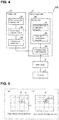
- Fig. 4 is a block diagram of an actuator control system 200. It is particularly preferable to use the actuator control system 200 as either the actuator control system 100 or the actuator control system 102.
- the actuator control system 200 includes a sensor unit 21 (excluding an object information acquiring unit 22, which will be described later), the control apparatus 2, and the drive circuit 3.
- the sensor unit 21 is constituted by the sensor unit 1, or the sensor units 1a and 1b.
- the sensor unit 21 includes an object information acquiring unit 22, a sensor output computation unit 23, and a transmission control unit 24.
- the object information acquiring unit 22 acquires information on the target object 8 (see Fig. 1 ). Specifically, the object information acquiring unit 22 captures an image of the target object 8, thereby acquiring a signal of the captured image of the target object 8. In the actuator control system 200, this signal is used as a sensor output signal.
- the signal of the captured image of the target object 8 is supplied from the object information acquiring unit 22 to the sensor output computation unit 23.
- the sensor output computation unit 23 performs a computation on the signal supplied to it.
- Fig. 5 shows diagrams of examples of the computation by the sensor output computation unit 23.
- Fig. 5(a) shows a rough search as a first position detecting process.
- the position of the target object 8 is detected from the captured image 31 at a first level of precision.
- the captured image 31 is split into a plurality of regions (16 regions in Fig. 5(a) ), and a region 32 containing a center position of the target object 8 is detected from among the plurality of regions.
- This rough search is performed in order to roughly detect the position of the target object 8, and thus the detection is performed at relatively high velocity although the first level of precision is relatively low.
- the coordinates of the position of the target object 8 obtained through the rough search are taken to be (x1,y1).
- Fig. 5(b) shows a fine search as a second position detecting process.
- the position of the target object 8 is detected from the captured image 31 at a second level of precision.
- the region 32 is split into a plurality of regions (16 regions in Fig. 5(b) ), and the position of the target object 8 is accurately detected by recognizing which region contains the center position of the target object 8.
- This fine search is performed in order to detect the position of the target object 8 more accurately than the rough search, and thus the second level of precision is higher than the first level of precision although the detection is performed more slowly than the rough search.
- the coordinates of the position of the target object 8 obtained through the fine search are taken to be (x2,y2).
- processing for the rough search is performed on a small image obtained through compression
- processing for the fine search is performed on the image before compression
- the transmission control unit 24 transmits final data, which is a final result of the computation by the sensor output computation unit 23, and also transmits intermediate data before transmitting the final data.
- the intermediate data is data indicating the coordinates (x1,y1), which is the detection result of the rough search
- the final data is data indicating the coordinates (x2,y2), which is the detection result of the fine search.
- the control apparatus 2 includes a command value computation unit 25 and a storage unit 26.
- the storage unit 26 stores an intermediate data computation program 27 and a final data computation program 28.
- the command value computation unit 25 is constituted by, for example, a CPU, and computes a command value for driving the actuator 4, based on the intermediate data and the final data transmitted by the transmission control unit 24.
- the command value computation unit 25 reads the intermediate data computation program 27 from the storage unit 26. Then, the command value computation unit 25 computes a preliminary command value for preliminarily driving the actuator 4, based on the intermediate data.
- the preliminary command value is a command value for moving the driving target 5 to a position corresponding to the coordinates (x1,y1).
- the command value computation unit 25 supplies the preliminary command value to the drive circuit 3, and the drive circuit 3 controls driving of the actuator 4 based on the supplied preliminary command value.
- the command value computation unit 25 reads the final data computation program 28 from the storage unit 26. Then, the command value computation unit 25 computes a command value for driving the actuator 4, based on the intermediate data and the final data.
- This command value is a command value for moving the driving target 5 to a position corresponding to the coordinates (x2,y2), in consideration of control for driving of the actuator 4 already performed based on the preliminary command value.
- the command value is for changing the state (position, velocity, and acceleration) of the driving target 5 in accordance with a difference between the coordinates (x1,y1) and the coordinates (x2,y2), wherein the driving of the actuator 4 is controlled to move the driving target 5 at low velocity if the difference is small, and at high velocity if the difference is large.
- the command value computation unit 25 supplies the command value to the drive circuit 3, and the drive circuit 3 controls driving of the actuator 4 based on the supplied command value.
- the command value computation unit 25 can receive intermediate data before receiving the final data. Accordingly, the command value computation unit 25 can perform its computation based on the intermediate data acquired before the sensor output computation unit 23 completes its computation of the final data. Thus, it is possible to control the actuator 4 at higher velocity or more precisely.
- the actuator control system 200 it is possible to preliminarily drive the actuator 4 in accordance with the preliminary command value based on the intermediate data. That is to say, it is possible to start the control for driving of the actuator 4 before the sensor output computation unit 23 completes its computation of the final data, and thus it is possible to perform the control at high velocity.
- positional detection at a relatively low level of precision is performed at high velocity in the rough search
- positional detection at a higher level of precision is performed in the fine search. Accordingly, it is possible to perform positional detection at higher velocity than when performing positional detection at a high level of precision from the beginning.
- a preliminary command value is calculated using a result of the rough search as intermediate data, and thus it is possible to start the control for driving of the actuator 4 before the sensor output computation unit 23 completes its computation of final data. That is to say, after driving of the actuator 4 is started based on the positional detection result with a relatively low level of precision, the driving of the actuator 4 can be completed to a precise position based on a positional detection result with a high level of precision, and thus it is possible to perform precise control at high velocity.
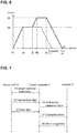
- Fig. 6 is a graph showing a relationship of the movement velocity of the driving target 5 toward the target object 8 with respect to the elapsed time.
- a time t1 is a time when the control for driving of the actuator 4 is started based on the preliminary command value.
- a time t2 is a time when the control for driving of the actuator 4 is started based on the command value.
- a time t3 is a time when control for driving of the actuator 4 is ended.
- the actuator 4 starts movement of the driving target 5 at time t1, and accelerates the driving target 5 at a constant acceleration until the movement velocity of the driving target 5 reaches a predetermined velocity va.
- the time when the movement velocity of the driving target 5 reaches the velocity va is the time ta.
- the actuator 4 moves the driving target 5 at a constant velocity (i.e., the velocity va) from the time ta to the time t2.
- the actuator 4 accelerates the movement of the driving target 5 from the time t2, and accelerates the driving target 5 at a constant acceleration until the movement velocity of the driving target 5 reaches a predetermined velocity vb.
- the time when the movement velocity of the driving target 5 reaches the velocity vb is the time tb.
- the actuator 4 moves the driving target 5 at a constant velocity (i.e., the velocity vb) from the time tb to a time tc.
- the actuator 4 decelerates the movement of the driving target 5 from the time tc, and decelerates the driving target 5 at a constant deceleration until the movement velocity of the driving target 5 reaches 0.
- the time when the movement velocity of the driving target 5 reaches 0 is the time t3.
- Fig. 7 is a timing chart showing an operation flow of the actuator control system 200. Note that a specific processing flow of the sensor unit 21 and the control apparatus 2 is as described with reference to Fig. 4 , and thus a description thereof has been omitted. Furthermore, the operation content of the drive circuit 3 does not directly affect the control content of driving of the actuator 4, and thus the drive circuit 3 is not shown in Fig. 7 .
- the control apparatus 2 transmits an image capturing instruction to the sensor unit 21 (Step S1). Subsequently, the sensor unit 21 transmits intermediate data to the control apparatus 2 (Step S2). Subsequently, the control apparatus 2 computes a preliminary command value based on the intermediate data, and preliminarily controls driving of the actuator 4 based on the preliminary command value (Step S3). Subsequently, the sensor unit 21 transmits final data to the control apparatus 2 (Step S4). Subsequently, the control apparatus 2 computes a command value based on the intermediate data and the final data, and controls driving of the actuator 4 based on the command value (Step S5). Lastly, the actuator 4 notifies the control apparatus 2 that driving is completed (Step S6).
- the sensor unit 21 is constituted by the sensor units 1a and 1b.
- examples of detection results of the rough search include not only the coordinates (x1,y1), which are two-dimensional coordinates of the target object 8, but also the three-dimensional coordinates (x1,y1,z1) of the target object 8 and the orientation of the target object 8.
- the coordinates (x1,y1) are mainly for determining whether or not the target object 8 is present.
- the three-dimensional coordinates (x1,y1,z1) are mainly for roughly determining the location at which the robot 5a serving as the driving target 5 grips the target object 8.
- the orientation of the target object 8 is mainly for roughly determining the method by which the robot 5a grips the target object 8.
- data of the coordinates (x1,y1), data of the three-dimensional coordinates (x1,y1,z1), or data of the orientation of the target object 8, or a combination of two or more types of this data can be used as the intermediate data.
- Fig. 8 is another timing chart showing an operation flow of the actuator control system 200.
- Fig. 8 can be referred to as an example of a timing chart according to the above-described specific application example. Note that a specific processing flow of the sensor unit 21 and the control apparatus 2 is as described with reference to Fig. 4 , and thus a description thereof has been omitted. Furthermore, the operation content of the drive circuit 3 does not directly affect the control content of driving of the actuator 4, and thus the drive circuit 3 is not shown in Fig. 8 .
- Fig. 9 is a block diagram of an actuator control system 300. It is particularly preferable to use the actuator control system 300 as the actuator control system 101.
- the actuator control system 300 includes the sensor unit 21 (excluding the object information acquiring unit 22), a control apparatus 2a, and the drive circuit 3.
- the control apparatus 2a includes a command value computation unit 25a and a storage unit 26a.
- the storage unit 26a stores the final data computation program 28 and a synchronization program 29.
- the command value computation unit 25a is constituted by, for example, a CPU, and computes a command value for driving the actuator 4, based on the intermediate data and the final data transmitted by the transmission control unit 24.
- the intermediate data is data of information at the time (image capturing time) when a signal (sensor output signal) of a captured image of the target object 8 is output from the object information acquiring unit 22.
- the command value computation unit 25a reads the synchronization program 29 from the storage unit 26a.
- the control information of the actuator 4 contains information indicating a current position of the driving target 5, and a latch time at which the actuator 4 latches a signal.
- the command value computation unit 25a synchronizes the sensor unit 21 and the actuator 4 based on the intermediate data and the control information.
- the command value computation unit 25a reads the final data computation program 28 from the storage unit 26a.
- the operations after the command value computation unit 25a reads the final data computation program 28 from the storage unit 26a are similar to those after the command value computation unit 25 reads the final data computation program 28 from the storage unit 26.
- the command value computation unit 25a can compute a command value in consideration of the time lag. Accordingly, it is possible to control the actuator 4 at a higher level of precision
- these units may be connected via a wire.
- the actuator control system 300 it is not necessary to provide wiring for such a wired connection. Accordingly, it is possible to simplify the hardware, and improve the degree of freedom in arranging the hardware.
- Fig. 10 is a timing chart showing an operation flow of the actuator control system 300. Note that a specific processing flow of the sensor unit 21 and the control apparatus 2a is as described with reference to Fig. 9 , and thus a description thereof has been omitted. Furthermore, the operation content of the drive circuit 3 does not directly affect the control content of driving of the actuator 4, and thus the drive circuit 3 is not shown in Fig. 10 .
- the control apparatus 2a transmits an image capturing instruction to the sensor unit 21 (Step S1a). At this time, the control apparatus 2a captures control information (current position, latch time) of the actuator 4 from the actuator 4 (Step S11). Subsequently, the sensor unit 21 transmits intermediate data to the control apparatus 2a (Step S2a). At this time, the control apparatus 2a captures control information (current position, latch time) of the actuator 4 from the actuator 4 (Step S21). Subsequently, the sensor unit 21 transmits final data to the control apparatus 2a (Step S4a). At this time, the control apparatus 2a captures control information (current position, latch time) of the actuator 4 from the actuator 4 (Step S31).
- control apparatus 2a computes a command value based on the intermediate data and the final data, and controls driving of the actuator 4 based on the command value (Step S5a). Lastly, the actuator 4 may notify the control apparatus 2a that driving is completed, via the drive circuit 3.
- Steps S11, S21, and S31 are performed in predetermined control cycles. Then, steps S1a, S2a, and S4a are respectively synchronized with steps S11, S21, and S31.
- the control apparatus 2a can obtain information of the image capturing time and information of the current position and the latch time of the actuator 4 at the timings of steps S2a and S21, and thus it is possible to start the computation of the command value before steps S4a and S31. Accordingly, it is possible to perform the processing at high velocity.
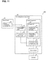
- Fig. 11 is a block diagram of an actuator control system 400. It is particularly preferable to use the actuator control system 400 as either the actuator control system 100 or the actuator control system 102.
- the actuator control system 400 includes an ILO integration component 41.
- the sensor head 40 includes the object information acquiring unit 22.
- the ILO integration component 41 includes the sensor output computation unit 23, the transmission control unit 24, the control apparatus 2, and the drive circuit 3. That is to say, in the actuator control system 400, the object information acquiring unit 22 constituting the sensor head 40 and the sensor output computation unit 23 and the transmission control unit 24 constituting the peripheral circuitry of the sensor head 40 are provided as separate members.
- the actuator control system 400 constituting the ILO integration component 41, and integrating and reconstructing a control logic, it is possible to reduce the apparatus size, to increase the velocity and precision of the control, and to simplify the control. Especially in the actuator control system 400, it can be expected to increase the velocity of throughput, to synchronize asynchronous control, and to share the above-described intermediate data, for example.
- the actuator control system 400 is obtained by applying, to the actuator control system 200, a configuration in which the object information acquiring unit 22, and the sensor output computation unit 23 and the transmission control unit 24 are provided as separate members. It is also possible to apply a configuration in which the object information acquiring unit 22, and the sensor output computation unit 23 and the transmission control unit 24 are provided as separate members to the actuator control system 300 in a similar manner.
- Figs. 12(a) to 12(c) are illustrations showing advantages of application of the ILO integration component 41.
- a system 500 in Fig. 12(a) is an example of a system in which the actuator control system 200 or 300 is mounted. In this case, in consideration of the movement velocity of the robot 5a that is the driving target 5, four robots 5a are necessary.
- a system 501 in Fig. 12(b) is an example of the system 500 in which the control apparatus 2, and members directly related to the operation of the control apparatus 2 are provided as one integrated circuit.
- the control apparatus 2 in consideration of the movement velocity of the robot 5a that is the driving target 5, it seems possible that two robots 5a operate at a similar velocity to that of the system 500.
- a system 502 in Fig. 12(c) is an example of a system in which the actuator control system 400 is mounted.
- the actuator control system 400 in consideration of the movement velocity of the robot 5a that is the driving target 5, it seems possible that one robot 5a operates at a similar velocity to that of the system 500.
- a threshold for the light receiving amount of a fiber sensor since a threshold for the light receiving amount of a fiber sensor is manually adjusted, it has to be readjusted when an environment (brightness) changes. If the light receiving amount of a fiber sensor is taken as intermediate data and used in a control apparatus, the threshold can be automatically adjusted. Accordingly, effects can be expected that the threshold is automatically adjusted (provided as feedback), the robustness against changes in an environment is improved, and malfunctions of the fiber sensor are detected at an early stage based on signs in the hardware. If the light receiving amount is made visible on a control apparatus or a display apparatus, malfunctions can be detected at an early stage based on signs in the hardware.
- the control block of the actuator control systems 200, 300, and 400 may be realized by a logical circuit (hardware) formed in an integrated circuit (IC chip) or the like, or may be realized by software using a CPU (central processing unit).
- a logical circuit hardware
- IC chip integrated circuit
- CPU central processing unit
- each of the actuator control systems 200, 300, and 400 includes a CPU that executes commands for a program, which is software that executes functions, a ROM (read only memory) or a storage apparatus (these are called “storage media”) that stores the above-described program and various types of data in a manner of being readable by a computer (or a CPU), a RAM (random access memory) for expanding the above-described program, and the like.
- the computer or CPU reads the above-described program from the above-described storage medium and executes it, whereby the object of the present invention is achieved.
- a "non-transitory tangible medium” such as a tape, a disk, a card, a semiconductor memory, or a programmable logic circuit can be used.
- the above-described program may be supplied to the above-described computer via any transmission medium (a communication network, a broadcasting wave, or the like) that can transmit the program.
- the present invention can also be realized in the form of a data signal embedded in a broadcasting wave in which the above-described program is realized by electronic transmission.
- An aspect of the present invention is directed to an actuator control system for controlling driving of an actuator based on a sensor output signal, the system including: a sensor output computation unit configured to perform a computation on the sensor output signal; a transmission control unit configured to transmit final data, which is a final result of the computation by the sensor output computation unit, and to transmit intermediate data before transmitting the final data; and a command value computation unit configured to compute a command value for driving the actuator, based on the intermediate data and the final data transmitted by the transmission control unit.
- the command value computation unit can receive intermediate data before receiving the final data. Accordingly, the command value computation unit can perform a computation based on the intermediate data acquired before the sensor output computation unit completes its computation of the final data. Thus, it is possible to control the actuator at higher velocity or more precisely.
- the command value computation unit computes a preliminary command value for preliminarily driving the actuator, based on the intermediate data.
- the sensor output signal is a signal of a captured image obtained by capturing an image of a target object
- the sensor output computation unit performs: a first position detecting process that detects a position of the target object at a first level of precision; and a second position detecting process that detects a position of the target object at a level of precision that is higher than the first level of precision
- the intermediate data is a detection result of the first position detecting process
- positional detection at a relatively low level of precision is performed at high velocity in the first position detecting process
- positional detection at a higher level of precision is performed in the second position detecting process. Accordingly, it is possible to perform positional detection at higher velocity than when performing positional detection at a high level of precision from the beginning.
- a preliminary command value is calculated using a result of the first position detecting process as intermediate data, and thus it is possible to start the control for driving of the actuator before the sensor output computation unit completes its computation of final data. That is to say, after driving of the actuator is started based on the positional detection result with a relatively low level of precision, the driving of the actuator can be completed to a precise position based on a positional detection result with a high level of precision, and thus it is possible to perform precise control at high velocity.
- the sensor output signal is a signal of a plurality of captured images obtained by capturing images of the target object from a plurality of angles
- the sensor output computation unit as the first position detecting process, detects the target object as two-dimensional coordinates from each of the plurality of captured images; and as the second position detecting process, detects three-dimensional coordinates of the target object based on the plurality of sets of two-dimensional coordinates.
- the intermediate data is information at a time when the sensor output signal is output, and the command value computation unit computes the command value with reference to the information at that time.
- the command value computation unit can compute a command value in consideration of this time lag. Accordingly, it is possible to control the actuator at a higher level of precision.
- these units may be connected via a wire.
- an aspect of the present invention is directed to an actuator control method for controlling driving of an actuator based on a sensor output signal, the method including: a sensor output computation step of performing a computation on the sensor output signal; a transmission control step of transmitting final data, which is a final result of the computation in the sensor output computation step, and transmitting intermediate data before transmitting the final data; and a command value computation step of computing a command value for driving the actuator, based on the intermediate data and the final data transmitted in the transmission control step.
- an information processing program for causing a computer to function as the actuator control system according to any one of the above-described aspects of the present invention, wherein the computer is caused to function as the above-described units, falls within the scope of the present invention.
- a computer-readable storage medium storing the above-described information processing program also falls within the scope of the present invention.
Landscapes
- Engineering & Computer Science (AREA)
- Physics & Mathematics (AREA)
- General Physics & Mathematics (AREA)
- Automation & Control Theory (AREA)
- Robotics (AREA)
- Mechanical Engineering (AREA)
- Computer Vision & Pattern Recognition (AREA)
- Theoretical Computer Science (AREA)
- Manipulator (AREA)
- Programmable Controllers (AREA)
- Image Processing (AREA)
- Image Analysis (AREA)
Claims (5)
- Aktuatorsteuerungssystem (100; 101; 102; 200; 300; 400) zum Steuern des Antriebs eines Aktuators (4) auf Basis eines Sensorausgabesignals, wobei das System Folgendes aufweist:eine Sensorausgabeberechnungseinheit (23), die eingerichtet ist, das Sensorausgabesignal einer Berechnung zu unterziehen;eine Übertragungssteuereinheit (24), die eingerichtet ist, finale Daten zu übertragen, die ein finales Ergebnis der Berechnung durch die Sensorausgabeberechnungseinheit (23) sind, und vor der Übertragung der finalen Daten Zwischendaten zu übertragen; undeine Befehlswertberechnungseinheit (25; 25a), die eingerichtet ist, einen Befehlswert zum Antrieb des Aktuators (4) zu berechnen, und zwar auf Basis der Zwischendaten und der finalen Daten, die von der Übertragungssteuereinheit (24) übertragen wurden;wobei das Sensorausgabesignal ein Signal eines aufgenommenen Bildes (31) ist, das durch die Aufnahme eines Bildes eines Zielobjekts (8) erhalten wurde;dadurch gekennzeichnet, dass die Sensorausgabeberechnungseinheit (23) Folgendes ausführt:einen ersten Positionserfassungsprozess zum Erfassen einer Position des Zielobjekts (8) mit einem ersten Präzisionsgrad; undeinen zweiten Positionserfassungsprozess zum Erfassen einer Position des Zielobjekts (8) mit einem zweiten Präzisionsgrad, der höher ist als der erste Präzisionsgrad,wobei die Zwischendaten ein Ergebnis der Erfassung des ersten Positionserfassungsprozesses sind,wobei die finalen Daten ein Ergebnis der Erfassung des zweiten Positionserfassungsprozesses sind,wobei die Befehlswertberechnungseinheit (25; 25a) einen vorläufigen Befehlswert zum vorläufigen Antrieb des Aktuators (4) an eine erste Position auf Basis der Zwischendaten ist,wobei die Befehlswertberechnungseinheit (25; 25a) einen Befehlswert zum Antrieb des Aktuators (4) an eine zweite Position auf Basis der Zwischendaten und der finalen Daten ist,wobei der Antrieb des Aktuators (4) so gesteuert wird, dass der Aktuator (4) sich mit geringer Geschwindigkeit bewegt, falls die Differenz zwischen der ersten Position und der zweiten Position klein ist, und mit sich mit großer Geschwindigkeit bewegt, falls die Differenz zwischen der ersten Position und der zweiten Position groß ist.
- Aktuatorsteuerungssystem (100; 101; 102; 200; 300; 400) gemäß Anspruch 1,
wobei das Sensorausgabesignal ein Signal von mehreren aufgenommenen Bildern (31) ist, die durch Aufnahme der Bilder des Zielobjekts (8) aus mehreren Winkeln erhalten wurden, und
die Sensorausgabeberechnungseinheit (23):als ersten Positionserfassungsprozess das Zielobjekt (8) als zweidimensionale Koordinaten aus jedem der mehreren aufgenommenen Bildern (31) erfasst; undals zweiten Positionserfassungsprozess die dreidimensionalen Koordinaten des Zielobjekts (8) auf Basis der mehreren Sätze von zweidimensionalen Koordinaten erfasst. - Aktuatorsteuerungsverfahren zum Steuern des Antriebs eines Aktuators (4) auf Basis eines Sensorausgabesignals, wobei das Verfahren Folgendes aufweist:einen Sensorausgabeberechnungsschritt, um das Sensorausgabesignal einer Berechnung zu unterziehen;einen Übertragungssteuerschritt, um finale Daten zu übertragen, die ein finales Ergebnis der Berechnung im Sensorausgabeberechnungsschritt sind, und vor der Übertragung der finalen Daten Zwischendaten zu übertragen; undeinen Befehlswertberechnungsschritt, um einen Befehl zum Antrieb des Aktuators (4) zu berechnen, und zwar auf Basis der Zwischendaten und der finalen Daten, die im Übertragungssteuerschruitt übertragen wurden;wobei das Sensorausgabesignal ein Signal eines aufgenommenen Bildes (31) ist, das durch die Aufnahme eines Bildes eines Zielobjekts (8) erhalten wurde;dadurch gekennzeichnet, dass der Sensorausgabeberechnungsschritt Folgendes umfasst:einen ersten Positionserfassungsprozess zum Erfassen einer Position des Zielobjekts (8) mit einem ersten Präzisionsgrad; undeinen zweiten Positionserfassungsprozess zum Erfassen einer Position des Zielobjekts (8) mit einem zweiten Präzisionsgrad, der höher ist als der erste Präzisionsgrad,wobei die Zwischendaten ein Ergebnis der Erfassung des ersten Positionserfassungsprozesses sind,wobei die finalen Daten ein Ergebnis der Erfassung des zweiten Positionserfassungsprozesses sind,wobei im Befehlswertberechnungsschritt ein vorläufiger Befehlswert zum vorläufigen Antrieb des Aktuators (4) an eine erste Position auf Basis der Zwischendaten berechnet wird,wobei im Befehlswertberechnungsschritt ein Befehlswert zum Antrieb des Aktuators (4) an eine zweite Position auf Basis der Zwischendaten und der finalen Daten berechnet wird, undwobei der Antrieb des Aktuators (4) so gesteuert wird, dass der Aktuator (4) sich mit geringer Geschwindigkeit bewegt, falls die Differenz zwischen der ersten Position und der zweiten Position klein ist, und mit sich mit großer Geschwindigkeit bewegt, falls die Differenz zwischen der ersten Position und der zweiten Position groß ist.
- Informationsverarbeitungsprogramm, das einen Computer als Aktuatorsteuerungssystem (100; 101; 102; 200; 300; 400) gemäß einem der Ansprüche 1 und 2 fungieren lässt, wenn man den Computer als die oben genannten Einheiten fungieren lässt.
- Computerlesbares Speichermedium, in dem das Informationsverarbeitungsprogramm gemäß Anspruch 4 gespeichert ist.
Applications Claiming Priority (2)
| Application Number | Priority Date | Filing Date | Title |
|---|---|---|---|
| JP2016082096A JP2017189856A (ja) | 2016-04-15 | 2016-04-15 | アクチュエータ制御システム、アクチュエータ制御方法、情報処理プログラム、および記録媒体 |
| PCT/JP2017/013935 WO2017179452A1 (ja) | 2016-04-15 | 2017-04-03 | アクチュエータ制御システム、アクチュエータ制御方法、情報処理プログラム、および記録媒体 |
Publications (3)
| Publication Number | Publication Date |
|---|---|
| EP3444080A1 EP3444080A1 (de) | 2019-02-20 |
| EP3444080A4 EP3444080A4 (de) | 2019-08-07 |
| EP3444080B1 true EP3444080B1 (de) | 2020-07-22 |
Family
ID=60042087
Family Applications (1)
| Application Number | Title | Priority Date | Filing Date |
|---|---|---|---|
| EP17782270.7A Active EP3444080B1 (de) | 2016-04-15 | 2017-04-03 | Aktuatorsteuerungssystem, aktuatorsteuerungsverfahren, informationsverarbeitungsprogramm und aufzeichnungsmedium |
Country Status (5)
| Country | Link |
|---|---|
| US (1) | US11209790B2 (de) |
| EP (1) | EP3444080B1 (de) |
| JP (1) | JP2017189856A (de) |
| CN (1) | CN108778637B (de) |
| WO (1) | WO2017179452A1 (de) |
Families Citing this family (7)
| Publication number | Priority date | Publication date | Assignee | Title |
|---|---|---|---|---|
| JP6734306B2 (ja) * | 2018-01-25 | 2020-08-05 | ファナック株式会社 | 物品搬送システムおよびロボットシステム |
| JP7467041B2 (ja) * | 2018-09-27 | 2024-04-15 | キヤノン株式会社 | 情報処理装置、情報処理方法及びシステム |
| CN113302027B (zh) * | 2019-01-30 | 2023-12-22 | 株式会社富士 | 作业坐标生成装置 |
| WO2020222845A1 (en) * | 2019-05-02 | 2020-11-05 | Siemens Aktiengesellschaft | External module for network connection to programmable logic controller (plc) backplane |
| US11633763B2 (en) * | 2019-12-16 | 2023-04-25 | Applied Vision Corporation | Sequential imaging for container sidewall inspection |
| CN114593111B (zh) * | 2020-12-03 | 2024-10-18 | 矻颀投资股份有限公司 | 一种具失效自我预知功能的致动器 |
| US12254383B2 (en) * | 2021-03-30 | 2025-03-18 | Accenture Global Solutions Limited | Intelligent real-time defect prediction, detection, and AI driven automated correction solution |
Family Cites Families (20)
| Publication number | Priority date | Publication date | Assignee | Title |
|---|---|---|---|---|
| JPH06137828A (ja) * | 1992-10-29 | 1994-05-20 | Kajima Corp | 障害物位置検出方法 |
| US6873880B2 (en) * | 2001-12-26 | 2005-03-29 | Lockheed Martin Corporation | Machine for performing machining operations on a workpiece and method of controlling same |
| JP2003211381A (ja) * | 2002-01-16 | 2003-07-29 | Denso Wave Inc | ロボット制御装置 |
| JP4202365B2 (ja) * | 2006-03-07 | 2008-12-24 | ファナック株式会社 | 力制御装置 |
| JP4226623B2 (ja) | 2006-09-29 | 2009-02-18 | ファナック株式会社 | ワーク取り出し装置 |
| DE102007060653A1 (de) * | 2007-12-15 | 2009-06-18 | Abb Ag | Positionsermittlung eines Objektes |
| JP5233601B2 (ja) | 2008-11-07 | 2013-07-10 | セイコーエプソン株式会社 | ロボットシステム、ロボット制御装置およびロボット制御方法 |
| JP2011133273A (ja) | 2009-12-22 | 2011-07-07 | Canon Inc | 推定装置及びその制御方法、プログラム |
| JP5316563B2 (ja) | 2011-02-15 | 2013-10-16 | オムロン株式会社 | 画像処理装置および画像処理システム |
| JP5849403B2 (ja) * | 2011-02-15 | 2016-01-27 | セイコーエプソン株式会社 | ロボットコントローラー、ロボット、及び、ロボットシステム |
| JP5803155B2 (ja) | 2011-03-04 | 2015-11-04 | セイコーエプソン株式会社 | ロボット位置検出装置及びロボットシステム |
| CN102218652B (zh) | 2011-05-09 | 2012-11-21 | 无锡引域智能机器人有限公司 | 一种利用机器人的柔顺性实现轴孔装配的装置和方法 |
| JP2012254518A (ja) * | 2011-05-16 | 2012-12-27 | Seiko Epson Corp | ロボット制御システム、ロボットシステム及びプログラム |
| JP2012240166A (ja) * | 2011-05-20 | 2012-12-10 | Fanuc Ltd | ビジョンセンサ及び吸引装置を備えた吸着搬送装置 |
| JP2013101045A (ja) * | 2011-11-08 | 2013-05-23 | Fanuc Ltd | 物品の3次元位置姿勢の認識装置及び認識方法 |
| JP5977544B2 (ja) * | 2012-03-09 | 2016-08-24 | キヤノン株式会社 | 情報処理装置、情報処理方法 |
| JP5928114B2 (ja) | 2012-04-12 | 2016-06-01 | セイコーエプソン株式会社 | ロボットシステム、ロボットシステムのキャリブレーション方法、ロボット |
| KR101438603B1 (ko) * | 2012-10-05 | 2014-09-05 | 현대자동차 주식회사 | 차량용 에어컨 시스템 |
| JP5765355B2 (ja) | 2013-03-18 | 2015-08-19 | 株式会社安川電機 | ロボットピッキングシステム及び被加工物の製造方法 |
| JP5786896B2 (ja) | 2013-06-07 | 2015-09-30 | 株式会社安川電機 | ワーク検出装置、ロボットシステム、被加工物の製造方法及びワーク検出方法 |
-
2016
- 2016-04-15 JP JP2016082096A patent/JP2017189856A/ja active Pending
-
2017
- 2017-04-03 WO PCT/JP2017/013935 patent/WO2017179452A1/ja not_active Ceased
- 2017-04-03 CN CN201780017243.8A patent/CN108778637B/zh active Active
- 2017-04-03 US US16/086,538 patent/US11209790B2/en active Active
- 2017-04-03 EP EP17782270.7A patent/EP3444080B1/de active Active
Non-Patent Citations (1)
| Title |
|---|
| None * |
Also Published As
| Publication number | Publication date |
|---|---|
| WO2017179452A1 (ja) | 2017-10-19 |
| JP2017189856A (ja) | 2017-10-19 |
| US11209790B2 (en) | 2021-12-28 |
| EP3444080A4 (de) | 2019-08-07 |
| EP3444080A1 (de) | 2019-02-20 |
| CN108778637B (zh) | 2021-07-13 |
| CN108778637A (zh) | 2018-11-09 |
| US20190101885A1 (en) | 2019-04-04 |
Similar Documents
| Publication | Publication Date | Title |
|---|---|---|
| US11209790B2 (en) | Actuator control system, actuator control method, information processing program, and storage medium | |
| US9604365B2 (en) | Device and method of transferring articles by using robot | |
| JP6632106B1 (ja) | 制御装置、移送装置、プログラム、及び、制御方法 | |
| US11541545B2 (en) | Information processing apparatus, information processing method, and system | |
| US9741108B2 (en) | Image processing apparatus and image processing system for conveyor tracking | |
| EP2581178B1 (de) | Werkstückentnahmesystem und Verfahren zur Herstellung eines zu verarbeitenden Materials | |
| CN108638066B (zh) | 一种用于机器人的传送带同步跟踪的装置、方法及系统 | |
| US11745350B2 (en) | Control method and control system of manipulator | |
| EP3229208B1 (de) | Kamerapositionseinschätzung | |
| CN110539299B (zh) | 机器手作业方法、控制器以及机器手系统 | |
| EP3936286A1 (de) | Robotersteuerungsvorrichtung, robotersteuerungsverfahren und robotersteuerungsprogramm | |
| JP2016147330A (ja) | 物体認識に基づく制御装置 | |
| US20170075331A1 (en) | Apparatus, system, and method for configuring and programming control of a robot | |
| CN118829511A (zh) | 用于安装部件组件的机器人系统和方法 | |
| CN109579698B (zh) | 一种智能货物检测系统及其检测方法 | |
| JP6838672B2 (ja) | アクチュエータ制御システム、センサ装置、制御装置、アクチュエータ制御方法、情報処理プログラム、および記録媒体 | |
| KR101412513B1 (ko) | 프레임 그래버 보드를 이용한 로봇팔 제어시스템 및 그 방법 | |
| CN104270568A (zh) | 一种相机同步拍摄控制装置 | |
| US10474124B2 (en) | Image processing system, image processing device, method of reconfiguring circuit in FPGA, and program for reconfiguring circuit in FPGA | |
| JP2014220657A (ja) | 画像測定装置及び画像測定プログラム | |
| CN110609555A (zh) | 用于信号控制的方法、装置、电子设备和计算机可读存储介质 | |
| EP3351927B1 (de) | Inspektionssystem, steuergerät, inspektionsverfahren und inspektionsprogramm | |
| US12397525B2 (en) | Planning movements for a servo press | |
| CN101206760A (zh) | 可重构控制器的视觉系统 | |
| CN112897038B (zh) | 机器人作业系统 |
Legal Events
| Date | Code | Title | Description |
|---|---|---|---|
| STAA | Information on the status of an ep patent application or granted ep patent |
Free format text: STATUS: THE INTERNATIONAL PUBLICATION HAS BEEN MADE |
|
| PUAI | Public reference made under article 153(3) epc to a published international application that has entered the european phase |
Free format text: ORIGINAL CODE: 0009012 |
|
| STAA | Information on the status of an ep patent application or granted ep patent |
Free format text: STATUS: REQUEST FOR EXAMINATION WAS MADE |
|
| 17P | Request for examination filed |
Effective date: 20180921 |
|
| AK | Designated contracting states |
Kind code of ref document: A1 Designated state(s): AL AT BE BG CH CY CZ DE DK EE ES FI FR GB GR HR HU IE IS IT LI LT LU LV MC MK MT NL NO PL PT RO RS SE SI SK SM TR |
|
| AX | Request for extension of the european patent |
Extension state: BA ME |
|
| DAV | Request for validation of the european patent (deleted) | ||
| DAX | Request for extension of the european patent (deleted) | ||
| A4 | Supplementary search report drawn up and despatched |
Effective date: 20190708 |
|
| RIC1 | Information provided on ipc code assigned before grant |
Ipc: B25J 9/16 20060101AFI20190702BHEP |
|
| REG | Reference to a national code |
Ref country code: DE Ref legal event code: R079 Ref document number: 602017020278 Country of ref document: DE Free format text: PREVIOUS MAIN CLASS: B25J0013080000 Ipc: B25J0009160000 |
|
| GRAP | Despatch of communication of intention to grant a patent |
Free format text: ORIGINAL CODE: EPIDOSNIGR1 |
|
| STAA | Information on the status of an ep patent application or granted ep patent |
Free format text: STATUS: GRANT OF PATENT IS INTENDED |
|
| RIC1 | Information provided on ipc code assigned before grant |
Ipc: B25J 9/16 20060101AFI20200129BHEP |
|
| INTG | Intention to grant announced |
Effective date: 20200220 |
|
| GRAS | Grant fee paid |
Free format text: ORIGINAL CODE: EPIDOSNIGR3 |
|
| GRAA | (expected) grant |
Free format text: ORIGINAL CODE: 0009210 |
|
| STAA | Information on the status of an ep patent application or granted ep patent |
Free format text: STATUS: THE PATENT HAS BEEN GRANTED |
|
| AK | Designated contracting states |
Kind code of ref document: B1 Designated state(s): AL AT BE BG CH CY CZ DE DK EE ES FI FR GB GR HR HU IE IS IT LI LT LU LV MC MK MT NL NO PL PT RO RS SE SI SK SM TR |
|
| REG | Reference to a national code |
Ref country code: GB Ref legal event code: FG4D |
|
| REG | Reference to a national code |
Ref country code: CH Ref legal event code: EP |
|
| REG | Reference to a national code |
Ref country code: DE Ref legal event code: R096 Ref document number: 602017020278 Country of ref document: DE |
|
| REG | Reference to a national code |
Ref country code: AT Ref legal event code: REF Ref document number: 1292975 Country of ref document: AT Kind code of ref document: T Effective date: 20200815 |
|
| REG | Reference to a national code |
Ref country code: IE Ref legal event code: FG4D |
|
| REG | Reference to a national code |
Ref country code: LT Ref legal event code: MG4D |
|
| REG | Reference to a national code |
Ref country code: AT Ref legal event code: MK05 Ref document number: 1292975 Country of ref document: AT Kind code of ref document: T Effective date: 20200722 |
|
| PG25 | Lapsed in a contracting state [announced via postgrant information from national office to epo] |
Ref country code: FI Free format text: LAPSE BECAUSE OF FAILURE TO SUBMIT A TRANSLATION OF THE DESCRIPTION OR TO PAY THE FEE WITHIN THE PRESCRIBED TIME-LIMIT Effective date: 20200722 Ref country code: LT Free format text: LAPSE BECAUSE OF FAILURE TO SUBMIT A TRANSLATION OF THE DESCRIPTION OR TO PAY THE FEE WITHIN THE PRESCRIBED TIME-LIMIT Effective date: 20200722 Ref country code: AT Free format text: LAPSE BECAUSE OF FAILURE TO SUBMIT A TRANSLATION OF THE DESCRIPTION OR TO PAY THE FEE WITHIN THE PRESCRIBED TIME-LIMIT Effective date: 20200722 Ref country code: PT Free format text: LAPSE BECAUSE OF FAILURE TO SUBMIT A TRANSLATION OF THE DESCRIPTION OR TO PAY THE FEE WITHIN THE PRESCRIBED TIME-LIMIT Effective date: 20201123 Ref country code: BG Free format text: LAPSE BECAUSE OF FAILURE TO SUBMIT A TRANSLATION OF THE DESCRIPTION OR TO PAY THE FEE WITHIN THE PRESCRIBED TIME-LIMIT Effective date: 20201022 Ref country code: NO Free format text: LAPSE BECAUSE OF FAILURE TO SUBMIT A TRANSLATION OF THE DESCRIPTION OR TO PAY THE FEE WITHIN THE PRESCRIBED TIME-LIMIT Effective date: 20201022 Ref country code: GR Free format text: LAPSE BECAUSE OF FAILURE TO SUBMIT A TRANSLATION OF THE DESCRIPTION OR TO PAY THE FEE WITHIN THE PRESCRIBED TIME-LIMIT Effective date: 20201023 Ref country code: ES Free format text: LAPSE BECAUSE OF FAILURE TO SUBMIT A TRANSLATION OF THE DESCRIPTION OR TO PAY THE FEE WITHIN THE PRESCRIBED TIME-LIMIT Effective date: 20200722 Ref country code: HR Free format text: LAPSE BECAUSE OF FAILURE TO SUBMIT A TRANSLATION OF THE DESCRIPTION OR TO PAY THE FEE WITHIN THE PRESCRIBED TIME-LIMIT Effective date: 20200722 Ref country code: SE Free format text: LAPSE BECAUSE OF FAILURE TO SUBMIT A TRANSLATION OF THE DESCRIPTION OR TO PAY THE FEE WITHIN THE PRESCRIBED TIME-LIMIT Effective date: 20200722 |
|
| PG25 | Lapsed in a contracting state [announced via postgrant information from national office to epo] |
Ref country code: RS Free format text: LAPSE BECAUSE OF FAILURE TO SUBMIT A TRANSLATION OF THE DESCRIPTION OR TO PAY THE FEE WITHIN THE PRESCRIBED TIME-LIMIT Effective date: 20200722 Ref country code: PL Free format text: LAPSE BECAUSE OF FAILURE TO SUBMIT A TRANSLATION OF THE DESCRIPTION OR TO PAY THE FEE WITHIN THE PRESCRIBED TIME-LIMIT Effective date: 20200722 Ref country code: LV Free format text: LAPSE BECAUSE OF FAILURE TO SUBMIT A TRANSLATION OF THE DESCRIPTION OR TO PAY THE FEE WITHIN THE PRESCRIBED TIME-LIMIT Effective date: 20200722 Ref country code: IS Free format text: LAPSE BECAUSE OF FAILURE TO SUBMIT A TRANSLATION OF THE DESCRIPTION OR TO PAY THE FEE WITHIN THE PRESCRIBED TIME-LIMIT Effective date: 20201122 |
|
| PG25 | Lapsed in a contracting state [announced via postgrant information from national office to epo] |
Ref country code: NL Free format text: LAPSE BECAUSE OF FAILURE TO SUBMIT A TRANSLATION OF THE DESCRIPTION OR TO PAY THE FEE WITHIN THE PRESCRIBED TIME-LIMIT Effective date: 20200722 |
|
| REG | Reference to a national code |
Ref country code: DE Ref legal event code: R097 Ref document number: 602017020278 Country of ref document: DE |
|
| PG25 | Lapsed in a contracting state [announced via postgrant information from national office to epo] |
Ref country code: CZ Free format text: LAPSE BECAUSE OF FAILURE TO SUBMIT A TRANSLATION OF THE DESCRIPTION OR TO PAY THE FEE WITHIN THE PRESCRIBED TIME-LIMIT Effective date: 20200722 Ref country code: DK Free format text: LAPSE BECAUSE OF FAILURE TO SUBMIT A TRANSLATION OF THE DESCRIPTION OR TO PAY THE FEE WITHIN THE PRESCRIBED TIME-LIMIT Effective date: 20200722 Ref country code: RO Free format text: LAPSE BECAUSE OF FAILURE TO SUBMIT A TRANSLATION OF THE DESCRIPTION OR TO PAY THE FEE WITHIN THE PRESCRIBED TIME-LIMIT Effective date: 20200722 Ref country code: EE Free format text: LAPSE BECAUSE OF FAILURE TO SUBMIT A TRANSLATION OF THE DESCRIPTION OR TO PAY THE FEE WITHIN THE PRESCRIBED TIME-LIMIT Effective date: 20200722 Ref country code: SM Free format text: LAPSE BECAUSE OF FAILURE TO SUBMIT A TRANSLATION OF THE DESCRIPTION OR TO PAY THE FEE WITHIN THE PRESCRIBED TIME-LIMIT Effective date: 20200722 Ref country code: IT Free format text: LAPSE BECAUSE OF FAILURE TO SUBMIT A TRANSLATION OF THE DESCRIPTION OR TO PAY THE FEE WITHIN THE PRESCRIBED TIME-LIMIT Effective date: 20200722 |
|
| PLBE | No opposition filed within time limit |
Free format text: ORIGINAL CODE: 0009261 |
|
| STAA | Information on the status of an ep patent application or granted ep patent |
Free format text: STATUS: NO OPPOSITION FILED WITHIN TIME LIMIT |
|
| PG25 | Lapsed in a contracting state [announced via postgrant information from national office to epo] |
Ref country code: AL Free format text: LAPSE BECAUSE OF FAILURE TO SUBMIT A TRANSLATION OF THE DESCRIPTION OR TO PAY THE FEE WITHIN THE PRESCRIBED TIME-LIMIT Effective date: 20200722 |
|
| 26N | No opposition filed |
Effective date: 20210423 |
|
| PG25 | Lapsed in a contracting state [announced via postgrant information from national office to epo] |
Ref country code: SK Free format text: LAPSE BECAUSE OF FAILURE TO SUBMIT A TRANSLATION OF THE DESCRIPTION OR TO PAY THE FEE WITHIN THE PRESCRIBED TIME-LIMIT Effective date: 20200722 |
|
| PG25 | Lapsed in a contracting state [announced via postgrant information from national office to epo] |
Ref country code: SI Free format text: LAPSE BECAUSE OF FAILURE TO SUBMIT A TRANSLATION OF THE DESCRIPTION OR TO PAY THE FEE WITHIN THE PRESCRIBED TIME-LIMIT Effective date: 20200722 |
|
| REG | Reference to a national code |
Ref country code: NL Ref legal event code: MP Effective date: 20200722 |
|
| PG25 | Lapsed in a contracting state [announced via postgrant information from national office to epo] |
Ref country code: MC Free format text: LAPSE BECAUSE OF FAILURE TO SUBMIT A TRANSLATION OF THE DESCRIPTION OR TO PAY THE FEE WITHIN THE PRESCRIBED TIME-LIMIT Effective date: 20200722 |
|
| GBPC | Gb: european patent ceased through non-payment of renewal fee |
Effective date: 20210403 |
|
| PG25 | Lapsed in a contracting state [announced via postgrant information from national office to epo] |
Ref country code: LU Free format text: LAPSE BECAUSE OF NON-PAYMENT OF DUE FEES Effective date: 20210403 |
|
| REG | Reference to a national code |
Ref country code: BE Ref legal event code: MM Effective date: 20210430 |
|
| PG25 | Lapsed in a contracting state [announced via postgrant information from national office to epo] |
Ref country code: GB Free format text: LAPSE BECAUSE OF NON-PAYMENT OF DUE FEES Effective date: 20210403 Ref country code: FR Free format text: LAPSE BECAUSE OF NON-PAYMENT OF DUE FEES Effective date: 20210430 Ref country code: CH Free format text: LAPSE BECAUSE OF NON-PAYMENT OF DUE FEES Effective date: 20210430 Ref country code: LI Free format text: LAPSE BECAUSE OF NON-PAYMENT OF DUE FEES Effective date: 20210430 |
|
| PG25 | Lapsed in a contracting state [announced via postgrant information from national office to epo] |
Ref country code: IE Free format text: LAPSE BECAUSE OF NON-PAYMENT OF DUE FEES Effective date: 20210403 |
|
| PG25 | Lapsed in a contracting state [announced via postgrant information from national office to epo] |
Ref country code: IS Free format text: LAPSE BECAUSE OF FAILURE TO SUBMIT A TRANSLATION OF THE DESCRIPTION OR TO PAY THE FEE WITHIN THE PRESCRIBED TIME-LIMIT Effective date: 20201122 |
|
| PG25 | Lapsed in a contracting state [announced via postgrant information from national office to epo] |
Ref country code: BE Free format text: LAPSE BECAUSE OF NON-PAYMENT OF DUE FEES Effective date: 20210430 |
|
| PG25 | Lapsed in a contracting state [announced via postgrant information from national office to epo] |
Ref country code: CY Free format text: LAPSE BECAUSE OF FAILURE TO SUBMIT A TRANSLATION OF THE DESCRIPTION OR TO PAY THE FEE WITHIN THE PRESCRIBED TIME-LIMIT Effective date: 20200722 |
|
| PG25 | Lapsed in a contracting state [announced via postgrant information from national office to epo] |
Ref country code: HU Free format text: LAPSE BECAUSE OF FAILURE TO SUBMIT A TRANSLATION OF THE DESCRIPTION OR TO PAY THE FEE WITHIN THE PRESCRIBED TIME-LIMIT; INVALID AB INITIO Effective date: 20170403 |
|
| PG25 | Lapsed in a contracting state [announced via postgrant information from national office to epo] |
Ref country code: MK Free format text: LAPSE BECAUSE OF FAILURE TO SUBMIT A TRANSLATION OF THE DESCRIPTION OR TO PAY THE FEE WITHIN THE PRESCRIBED TIME-LIMIT Effective date: 20200722 |
|
| PG25 | Lapsed in a contracting state [announced via postgrant information from national office to epo] |
Ref country code: TR Free format text: LAPSE BECAUSE OF FAILURE TO SUBMIT A TRANSLATION OF THE DESCRIPTION OR TO PAY THE FEE WITHIN THE PRESCRIBED TIME-LIMIT Effective date: 20200722 |
|
| PG25 | Lapsed in a contracting state [announced via postgrant information from national office to epo] |
Ref country code: MT Free format text: LAPSE BECAUSE OF FAILURE TO SUBMIT A TRANSLATION OF THE DESCRIPTION OR TO PAY THE FEE WITHIN THE PRESCRIBED TIME-LIMIT Effective date: 20200722 |
|
| PGFP | Annual fee paid to national office [announced via postgrant information from national office to epo] |
Ref country code: DE Payment date: 20250417 Year of fee payment: 9 |