EP3229208B1 - Kamerapositionseinschätzung - Google Patents
Kamerapositionseinschätzung Download PDFInfo
- Publication number
- EP3229208B1 EP3229208B1 EP16206592.4A EP16206592A EP3229208B1 EP 3229208 B1 EP3229208 B1 EP 3229208B1 EP 16206592 A EP16206592 A EP 16206592A EP 3229208 B1 EP3229208 B1 EP 3229208B1
- Authority
- EP
- European Patent Office
- Prior art keywords
- image
- points
- contour
- processing unit
- pose
- Prior art date
- Legal status (The legal status is an assumption and is not a legal conclusion. Google has not performed a legal analysis and makes no representation as to the accuracy of the status listed.)
- Active
Links
Images


Classifications
-
- G—PHYSICS
- G06—COMPUTING OR CALCULATING; COUNTING
- G06T—IMAGE DATA PROCESSING OR GENERATION, IN GENERAL
- G06T7/00—Image analysis
- G06T7/70—Determining position or orientation of objects or cameras
- G06T7/73—Determining position or orientation of objects or cameras using feature-based methods
- G06T7/75—Determining position or orientation of objects or cameras using feature-based methods involving models
-
- G—PHYSICS
- G06—COMPUTING OR CALCULATING; COUNTING
- G06T—IMAGE DATA PROCESSING OR GENERATION, IN GENERAL
- G06T7/00—Image analysis
- G06T7/10—Segmentation; Edge detection
- G06T7/13—Edge detection
-
- G—PHYSICS
- G06—COMPUTING OR CALCULATING; COUNTING
- G06T—IMAGE DATA PROCESSING OR GENERATION, IN GENERAL
- G06T7/00—Image analysis
- G06T7/30—Determination of transform parameters for the alignment of images, i.e. image registration
- G06T7/33—Determination of transform parameters for the alignment of images, i.e. image registration using feature-based methods
-
- G—PHYSICS
- G06—COMPUTING OR CALCULATING; COUNTING
- G06T—IMAGE DATA PROCESSING OR GENERATION, IN GENERAL
- G06T2207/00—Indexing scheme for image analysis or image enhancement
- G06T2207/30—Subject of image; Context of image processing
- G06T2207/30108—Industrial image inspection
- G06T2207/30164—Workpiece; Machine component
-
- G—PHYSICS
- G06—COMPUTING OR CALCULATING; COUNTING
- G06T—IMAGE DATA PROCESSING OR GENERATION, IN GENERAL
- G06T2207/00—Indexing scheme for image analysis or image enhancement
- G06T2207/30—Subject of image; Context of image processing
- G06T2207/30244—Camera pose
-
- G—PHYSICS
- G06—COMPUTING OR CALCULATING; COUNTING
- G06V—IMAGE OR VIDEO RECOGNITION OR UNDERSTANDING
- G06V2201/00—Indexing scheme relating to image or video recognition or understanding
- G06V2201/06—Recognition of objects for industrial automation
Definitions
- the present disclosure relates generally to cameras and, more particularly, to camera pose estimation.
- the present disclosure may provide cameras to be employed in manufacturing complex products.
- Robots with mounted cameras may be employed in manufacturing of complex products, such as aircraft. However, it is important that the robot is correctly positioned relative to the aircraft in order to prevent damage to both the robot and the aircraft.
- the camera mounted on the robot may be used to help determine the position of the robot. More specifically, once a pose of the camera is determined, a pose of the robot can be determined. The pose is typically defined as a position and an orientation of an object. Example of an estimation of a camera position based on a silhouette matching with rendered 3D model and camera data can be found in J. Karlekar et al., "Positioning, Tracking and Mapping for Outdoor Augmentation", IEEE International Symposium on Mixed and Augmented Reality 2010 .
- a system for determining a camera pose relative to an object including a unique feature according to claim 1 is disclosed. Further refinements of the system according to claims 2-11 are disclosed.
- a method for determining a camera pose relative to a object including a unique feature according to claim 12 is disclosed. Further refinements of the method according to claims 13-15 are disclosed.
- a non-transitory computer-readable storage medium storing instructions which when executed by a processor determines a pose of a monocular camera relative to an object.
- the non-transitory computer-readable storage medium may comprise instructions for: storing a three-dimensional (3D) reference model of the object; receiving a two-dimensional (2D) image of the object captured by the monocular camera; identifying a contour of the object in the 2D image; identifying a unique feature on the contour of the object in the 2D image; synthesizing at least four points on the contour in the 2D image by starting at the unique feature, traversing the contour, and dividing the contour into equidistant segments; synthesizing a same number of points as synthesized in the 2D image with the unique feature as the starting point along a contour of the object in the 3D reference model; and aligning the points synthesized in the 3D reference model with the at least four points synthesized in the 2D image to generate a rough estimate of the pose of the monocular
- the non-transitory computer-readable storage medium may further comprise instructions for calculating a perspective-n-point problem on the aligned points synthesized from the 3D reference model to the 2D image in order to generate the rough estimate of the pose of the monocular camera.
- the non-transitory computer-readable storage medium may further comprise instructions for using lens equations to calculate a total projection error based on the rough estimate of the pose of the monocular camera.
- the non-transitory computer-readable storage medium may further comprise instructions for performing bounded nonlinear optimization to minimize the total projection error and generate a refined estimate of the pose of the monocular camera.
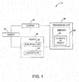
- the system 20 includes a camera 24 and a processing unit 26 in operative communication with the camera 24.
- the camera 24 is configured to produce a two-dimensional (2D) image of the object 22.
- the camera 24 comprises a single calibrated monocular camera, although other types of cameras may be used.
- the camera 24 is operatively mounted on a robot 30.
- the robot 30 is configured to perform work on the object 22 and includes an end effector 32 and a robot controller 34.
- the end effector 32 is configured to be deployed into the object 22, while the robot controller 34 is configured to control movement of the end effector 32 and the robot 30.
- the object 22 is a portal 36 in an aircraft wing 38.
- the object 22 includes a contour 40 and a unique feature 42.
- the contour 40 of the object 22 is an outline 44 of the aircraft wing portal 36
- the unique feature 42 of the object 22 is a notch 46 in the outline 44 of the aircraft wing portal 36.
- the object 22, the contour 40, and the unique feature 42 can be of any other type.
- the object 22 may be relatively featureless except for one unique feature, or may alternatively have more than one unique feature.
- the robot 30 In order to deploy the end effector 32 of the robot 30 into the portal 36 of the aircraft wing 38, the robot 30 is advantageously positioned in a correct location.
- a pose, defined herein as a position and an orientation, of the robot 30 is determined in order to correctly position the robot 30 relative to the portal 36.
- the robot pose can be determined from the pose, or the position and the orientation, of the camera 24 relative to the portal 36 of the aircraft wing 38.
- the camera pose is determined by the processing unit 26 from a 2D image of the object 22 produced by the camera 24.
- the processing unit 26 is in operative communication with the camera 24 and the robot 30, such as with the robot controller 34.
- the processing unit 26 is implemented using one or more of a processor, a microprocessor, a microcontroller, a digital signal processor (DSP), a field-programmable gate array (FPGA), an electronic control module (ECM), an electronic control unit (ECU), and a processor-based device that may include or be associated with a non-transitory computer readable storage medium having stored thereon computer-executable instructions, or any other suitable means for electronically controlling functionality of the system 20.
- DSP digital signal processor
- FPGA field-programmable gate array
- ECM electronic control module
- ECU electronic control unit
- the processing unit 26 may be configured to operate according to predetermined algorithms or sets of instructions for operating the system 20. Such algorithms or sets of instructions may be programmed or incorporated into a memory 28 associated with or at least accessible to the processing unit 26.
- the memory 28 may comprise a non-volatile memory provided within and/or external to the processing unit 26. It is understood that the processing unit 26 and the system 20 may include other hardware, software, firmware, and combinations thereof.
- the robot controller 34 comprises a processor-based device with an associated memory for electronically controlling functionality of the robot 30 and the end effector 32.
- the processing unit 26 is configured to receive the 2D image of the object 22 produced by the camera 24, determine the pose of the camera 24 relative to the object 22 using the 2D image, and send signals indicative of the determined camera pose to the robot controller 34.
- the robot controller 34 is configured to determine the pose of the robot 30 based on the determined camera pose and position the robot 30 for deployment of the end effector 32 into the object 22 based on the determined robot pose.
- FIG. 3 a flowchart illustrating an example algorithm or process 70 for determining a camera pose is shown, in accordance with another embodiment.
- the example algorithm or process 70 is programmed into the memory 28 of the processing unit 26.
- the processing unit 26 receives an image of the object 22 from the camera 24.
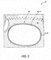
- the camera 24 produces an image 48 of the portal 36, as shown in FIG. 4 , and sends data indicative of the image 48 to the processing unit 26.
- pre-processing techniques are applied to the image data.
- Camera calibration information is used in the pre-processing techniques.
- pre-processing techniques include un-distortion of the image 48, conversion of the image 48 to gray-scale, and smoothing of the image 48.
- other techniques may also be used.
- the object 22, such as the portal 36 is identified in the image 48.
- blob analysis is used to identify the object 22, although other techniques may be used. For example, using blob analysis, a largest blob in the image 48 is identified as the portal 36.
- the contour 40 of the object 22 is identified in the image 48.
- Blob analysis and/or edge detection is used to identify the contour 40 of the object 22, such as the outline 44 of the portal 36.
- other techniques may be used.
- the unique feature 42 of the object 22 is identified in the image 48. Pattern matching, edge detection, and other techniques are used to identify the unique feature 42. For instance, after the contour 40 of the object 22 is identified, the unique feature 42, such as the notch 46, is identified on the contour 40 of the object 22.
- a location of the unique feature 42 in the image 48 is obtained from identifying the unique feature 42 at block 80.
- the contour 40 of the object 22 in the image 48 is segmented into a plurality of points 50 ( FIG. 4 ). More specifically, after identification of the unique feature 42 on the contour 40, the unique feature 42 is used as a starting point 52 ( FIG. 4 ) to traverse the contour 40 in the image 48 and synthesize the plurality of points 50 via segmentation. Synthesis of the plurality of points 50 results in equidistant segments 54 ( FIG. 4 ). In addition, the unique feature 42 provides a point of reference to begin contour segmentation. In an embodiment, the processing unit 26 is programmed to perform contour segmentation to synthesize the plurality of points 50 via Freeman chain code. However, other algorithms may be used.
- a number for the plurality of points 50 can be predetermined and preprogrammed into the memory 28 of the processing unit 26. In an embodiment, at least four points are synthesized on the contour 40 of the object 22.
- the predetermined number for the plurality of points 50 may be a function of the camera 24, the object 22, a size of the object 22, and the like. In one example, the number of synthesized points may be one hundred, and in another example, the number of synthesized points may be fifty. However, other numbers of synthesized points may be used.
- the outline 44 of the aircraft wing portal 36 is traversed in a clockwise direction or a counterclockwise direction and segmented by synthesizing the plurality of points 50.
- the processing unit 26 divides the outline 44 in the image 48 into equidistant points 50 and segments 54 based on the number of points preprogrammed into the memory 28. For instance, the processing unit 26 arranges the plurality of points 50 on the outline 44 such that the notch 46 is the first point on the contour 40. In so doing, contour segmentation allows for identification of only one feature of the object 22 to determine the camera pose.
- the plurality of points 50 on the contour 40 of the object 22 in the image 48, or image points, are generated at block 86.
- a three-dimensional (3D) reference model 56 ( FIG. 1 ) of the object 22 is preprogrammed into the memory 28 of the processing unit 26.
- the reference model includes data indicative of a geometry, design, scale, and feature coordinates of the object 22 in 3D space.
- the reference model 56 is a computer-aided design (CAD) model.
- CAD computer-aided design
- An example of the reference model 56 of the aircraft wing portal 36 is shown in FIG. 5 .
- the reference model 56 also includes the segmented contour 40 with a same number of a plurality of points 60 as synthesized in the image 48. More specifically, the same number of points is synthesized along the contour 40 of the object 22 in the reference model 56 as synthesized in the image 48.
- the contour 40 or the outline 44 of the aircraft wing portal 36 in the reference model 56 is traversed and segmented with the unique feature 42 as the starting point.
- the processing unit 26 divides the outline 44 in the reference model 56 into the same number of equidistant points 60 and segments as in the image 48, based on the number of points preprogrammed into the memory 28. For instance, the processing unit 26 arranges the plurality of points 60 on the outline 44 such that the notch 46 is the first point on the contour 40 in the reference model 56.
- the plurality of points 60 on the contour 40 of the object 22 in the reference model 56, or CAD data points, are generated, such as at block 88.
- the unique feature 42 of the object 22 is identified in the reference model 56 using the data preprogrammed into the memory 28.
- a feature location in the reference model 56 is obtained from identifying the unique feature 42.
- data from blocks 88, 90, and 92 associated with the reference model 56 are preprogrammed into the memory 28 of the processing unit 26.
- point correspondence between the CAD data points and the image points is determined. More specifically, the points synthesized in the reference model 56 are aligned with the points synthesized in the image 48.
- the plurality of points 60 from the segmented contour 40 in the reference model 56 are correlated to the plurality of points 50 from the segmented contour 40 in the image 48.
- For each of the correlated points in the segmented contour 40 there are (u, v) coordinates from the 2D image 48 and (x, y, z) coordinates from the 3D reference model 56.
- the camera pose is calculated based on the correlated points from block 94.
- the perspective-n-point problem is used to calculate the camera pose using the (u, v) coordinates and the (x, y, z) coordinates for each of the correlated points.
- the perspective-n-point problem also uses the camera calibration information. For instance, the (u, v) coordinates, the (x, y, z) coordinates, and the camera calibration information are input into the perspective-n-point problem, which then outputs the camera pose, or the position and the orientation of the camera 24 in 3D space.
- a rough estimate of the camera pose is obtained from the perspective-n-point problem.
- nonlinear optimization is performed on the rough estimate of the camera pose.
- the nonlinear optimization minimizes a total projection error from projection or re-projection between the CAD data points and the image points. More specifically, an error for each of the correlated points is a distance between a CAD data point and its corresponding image point, which is also known as the Euclidean distance.
- the total projection error is the sum of the squares of the Euclidean distances for all the correlated points. In one embodiment, the total projection error is determined using camera homography via lens equations.
- nonlinear optimization For example, gradient descent, a type of nonlinear optimization, is used to minimize the total projection error. However, other types of nonlinear optimization may be used. Furthermore, at block 102, the nonlinear optimization is bounded, or constrained between a lower optimization bound and an upper optimization bound. However, the nonlinear optimization may also be unbounded.
- parameters of the camera pose such as a translation and a rotation
- the lower and upper optimization bounds are preprogrammed into the memory 28 of the processing unit 26 based on predetermined knowledge of allowed error in the robotic manufacturing process of the object.
- the lower and upper optimization bounds are a function of the total projection error.
- a refined estimate of the camera pose is generated from nonlinear optimization of the rough estimate of the camera pose.
- the nonlinear optimization converges minimization of the total projection error when a solution is found or a change in the total projection error is less than a specified tolerance.
- the specified tolerance is a predetermined acceptable pixel error in the robotic manufacturing process of the object.
- the specified tolerance is preprogrammed into the memory 28 of the processing unit 26, which is configured to stop performance of the nonlinear optimization at the specified tolerance.
- the refined estimate of the camera pose is used to determine the robot pose.
- a signal indicative of the refined estimate of the camera pose generated from the nonlinear optimization and/or the robot pose is sent from the processing unit 26 to the robot controller 34 of the robot 30.
- the robot controller 34 based on the camera pose and/or the robot pose, the robot controller 34 then positions the robot 30 such that deployment of the end effector 32 is directed into the object 22. For instance, the robot controller 34 positions the robot 30 in a correct position for the end effector 32 to be deployed into the portal 36 without colliding into the aircraft wing 38. In so doing, damage to the robot 30 and the aircraft wing 38 may be prevented by determining a refined estimate of the camera pose.
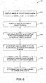
- FIG. 6 a flowchart illustrating another example algorithm or process 120 for determining a camera pose is shown, in accordance with another embodiment.
- the example algorithm or process 120 is programmed into the memory 28 of the processing unit 26.
- the image 48 of the object 22 is received from the camera 24.
- the unique feature 42 of the object 22 is identified in the image 48, at block 124. At least four points on the contour 40 of the object 22 are synthesized using the unique feature 42 as a starting point, at block 126. At block 128, the same number of points on the contour 40 of the object 22 in the CAD model, or reference model 56, are synthesized as the at least four points synthesized in the image 48. The points from the contour 40 in the CAD model, or reference model 56, are correlated to the contour 40 in the image 48, at block 130. At block 132, the camera pose is determined based on the correlated points.
- the present disclosure provides systems and methods for determining a camera pose. More specifically, the disclosed systems and methods are used to determine the pose of a monocular camera.
- the monocular camera may be mounted to a robot used in manufacturing of aircraft.
- the disclosed systems and methods identify one unique feature on a contour of an object.
- the disclosed systems and methods then utilize the one unique feature as a starting point for segmentation of the contour.
- contour segmentation at least four points may be synthesized in the image and the reference model for solving of the perspective-n-point problem.
- identification of only one unique feature is necessary to estimate camera pose, as opposed to prior art applications in which identification of four unique features was necessary to solve the perspective-n-point problem.
- camera pose estimation relative to a generally featureless object may be achieved.
- FIGS. 3 and 6 are shown and described as examples only to assist in disclosing the features of the disclosed systems, and that more or less steps than shown may be included in the processes corresponding to the various features described above for the disclosed system without departing from the scope of the disclosure.
Landscapes
- Engineering & Computer Science (AREA)
- Computer Vision & Pattern Recognition (AREA)
- Physics & Mathematics (AREA)
- General Physics & Mathematics (AREA)
- Theoretical Computer Science (AREA)
- Image Analysis (AREA)
- Image Processing (AREA)
Claims (15)
- System (20) zum Bestimmen einer Kameralage relativ zu einem Objekt (22), das ein eindeutiges Merkmal (42) aufweist, mit:einer monokularen Kamera (24), die dafür konfiguriert ist, ein Bild (48) des Objekts (22) zu erzeugen; undeiner mit der monokularen Kamera (24) betrieblich verbundenen Verarbeitungseinheit (26), wobei die Verarbeitungseinheit (26) dafür konfiguriert ist:eine Kontur (40) des Objekts (22) im Bild (48) zu identifizieren;das eindeutige Merkmals (42) an der Kontur (40) des Objekts (22) in dem durch die monokulare Kamera (24) erzeugten Bild (48) zu identifizieren;mindestens vier Punkten (50) entlang der Kontur (40) des Objekts (22) im Bild (48) unter Verwendung des identifizierten eindeutigen Merkmals (42) als ein Startpunkt (52) zu synthetisieren;eine Anzahl von Punkten (60), die der Anzahl der im Bild (48) synthetisierten Punkte gleicht, mit dem eindeutigen Merkmal (42) als Startpunkt entlang einer Kontur (40) des Objekts (22) in einem dreidimensionalen Referenzmodell (56) zu synthetisieren, wobei das Referenzmodell (56) in einem Speicher (28) der Verarbeitungseinheit (26) vorprogrammiert ist;die Punkte (60) vom Referenzmodell (56) mit den Punkten (50) von der Kontur (40) im Bild (48) zu korrelieren; undeine Lage der monokularen Kamera (24) basierend auf den korrelierten Punkten (60) zu bestimmen.
- System nach Anspruch 1, wobei die Verarbeitungseinheit (26) ferner dafür konfiguriert ist, eine Blob-Analyse zum Identifizieren der Kontur (40) des Objekts (22) im Bild (48) zu verwenden.
- System nach einem der vorangehenden Ansprüche, wobei die Verarbeitungseinheit (26) ferner dafür konfiguriert ist, einen Musterabgleich oder eine Kantenerfassung zum Identifizieren des eindeutigen Merkmals (42) im Bild (48) zu verwenden.
- System nach einem der vorangehenden Ansprüche, wobei die Verarbeitungseinheit (26) ferner dafür konfiguriert ist, die Kontur (40) des Objekts (22) im Bild (48) in äquidistante Segmente (54) zu teilen, wenn die mindestens vier Punkte (50) synthetisiert werden.
- System nach Anspruch 4, wobei die Verarbeitungseinheit (26) ferner dafür konfiguriert ist, die Kontur (40) des Objekts (22) im Referenzmodell (56) in eine gleiche Anzahl äquidistanter Segmente (54) zu teilen, wie die Anzahl der im Bild (48) geteilten Segmente, wenn die gleiche Anzahl von Punkten (60) im Referenzmodell (56) synthetisiert wird.
- System nach einem der vorangehenden Ansprüche, wobei die Verarbeitungseinheit (26) ferner dafür konfiguriert ist, eine grobe Schätzung der Lage der monokularen Kamera (24) aus der Korrelation der Punkte (60) vom Referenzmodell (56) mit den Punkten (50) von der Kontur (40) in dem Bild (48) unter Verwendung eines Perspective-N-Point-Problems zu erzeugen.
- System nach Anspruch 6, wobei die Verarbeitungseinheit (26) ferner dafür konfiguriert ist, eine verfeinerte Schätzung der Lage der monokularen Kamera (24) durch Ausführen einer nichtlinearen Optimierung bezüglich der groben Schätzung der Lage zu erzeugen.
- System nach Anspruch 7, wobei die monokulare Kamera (24) an einem Roboter (30) montiert ist, der einen Endeffektor (32) aufweist, der dafür konfiguriert ist, in das Objekt (22) bewegt zu werden, und eine Robotersteuereinheit (34), die dafür konfiguriert ist, die Bewegung des Endeffektors (32) zu steuern, wobei die Robotersteuereinheit (34) mit dem Endeffektor (32) und mit der Verarbeitungseinheit (26) betrieblich verbunden ist.
- System nach Anspruch 8, wobei die Verarbeitungseinheit (26) ferner dafür konfiguriert ist, ein die verfeinerte Schätzung der Lage der monokularen Kamera (24) anzeigendes Signal an die Robotersteuereinheit (34) zu übertragen, um den Endeffektor (32) in das Objekt (22) zu bewegen.
- System nach Anspruch 7, wobei die nichtlineare Optimierung zwischen einer unteren Optimierungsgrenze und einer oberen Optimierungsgrenze begrenzt ist.
- System nach Anspruch 10, wobei die Verarbeitungseinheit (26) ferner dafür konfiguriert ist, die Ausführung der nichtlinearen Optimierung bei einer spezifizierten Toleranz zu stoppen.
- Verfahren (70) zum Bestimmen einer Kameralage relativ zu einem Objekt (22), das ein eindeutiges Merkmal aufweist, mit den Schritten:Empfangen (122) eines Bildes (48) eines Objekts (22) von einer monokularen Kamera (24);Identifizieren einer Kontur (40) des Objekts (22) in dem Bild (48);Identifizieren (124) eines eindeutigen Merkmals (42) des Objekts (22) an der Kontur (40) im Bild (48);Verwenden (126) des identifizierten eindeutigen Merkmals (42) als ein Startpunkt (52) zum Synthetisieren von mindestens vier Punkten (50) an der Kontur (40) des Objekts (22) im Bild (48);Synthetisieren (128) einer gleichen Anzahl von Punkten (60), wie die Anzahl synthetisierter Punkt im Bild (48), mit dem eindeutigen Merkmal (42) als der Startpunkt entlang einer Kontur (40) des Objekts (22) in einem dreidimensionalen computergestützten Designmodell (56);Korrelieren (130) der Punkte (60) von der Kontur (40) in dem computergestützten Designmodell (56) mit den Punkten (50) von der Kontur (40) im Bild (48); undBestimmen (132) einer Lage der monokularen Kamera (24) basierend auf den korrelierten Punkten (60).
- Verfahren nach Anspruch 12, ferner mit den Schritten:Teilen der Kontur (40) des Objekts (22) im Bild (48) in äquidistante Segmente (54) beginnend bei dem identifizierten eindeutigen Merkmal (42), um die mindestens vier Punkte (50) zu synthetisieren; undTeilen der Kontur (40) des Objekts im computergestützten Designmodell (56) in eine gleiche Anzahl äquidistanter Segmenten (54), wie die Anzahl der geteilten Segmente im Bild (48), um eine gleiche Anzahl von Punkten (60) im computergestützten Designmodell (56) zu synthetisieren, wie die Anzahl der mindestens vier Punkte im Bild (48).
- Verfahren nach Anspruch 12 oder 13, ferner mit dem Verwenden einer Reprojektion zum Korrelieren der Punkte (60) von der Kontur (40) im computergestützten Designmodell (56) mit den Punkten (50) von der Kontur (40) im Bild (48).
- Verfahren nach Anspruch 14, ferner mit dem Minimieren eines Gesamtprojektionsfehlers von einer Reprojektion durch ein Gradienten(Gradient Descent)verfahren und optionale konvergierende Minimierung des Gesamtprojektionsfehlers bei einer spezifizierten Toleranz.
Applications Claiming Priority (1)
| Application Number | Priority Date | Filing Date | Title |
|---|---|---|---|
| US15/093,453 US9824451B2 (en) | 2016-04-07 | 2016-04-07 | Camera pose estimation |
Publications (2)
| Publication Number | Publication Date |
|---|---|
| EP3229208A1 EP3229208A1 (de) | 2017-10-11 |
| EP3229208B1 true EP3229208B1 (de) | 2018-10-31 |
Family
ID=57914649
Family Applications (1)
| Application Number | Title | Priority Date | Filing Date |
|---|---|---|---|
| EP16206592.4A Active EP3229208B1 (de) | 2016-04-07 | 2016-12-23 | Kamerapositionseinschätzung |
Country Status (2)
| Country | Link |
|---|---|
| US (1) | US9824451B2 (de) |
| EP (1) | EP3229208B1 (de) |
Families Citing this family (8)
| Publication number | Priority date | Publication date | Assignee | Title |
|---|---|---|---|---|
| US10733848B2 (en) | 2016-09-27 | 2020-08-04 | Igt | Gaming system and method providing a wagering game with a bonus card feature |
| US11315278B1 (en) * | 2018-09-27 | 2022-04-26 | Apple Inc. | Object detection and orientation estimation |
| WO2020131880A1 (en) * | 2018-12-17 | 2020-06-25 | The Brigham And Women's Hospital, Inc. | System and methods for a trackerless navigation system |
| US11798299B2 (en) * | 2019-10-31 | 2023-10-24 | Bodygram, Inc. | Methods and systems for generating 3D datasets to train deep learning networks for measurements estimation |
| US11423605B2 (en) * | 2019-11-01 | 2022-08-23 | Activision Publishing, Inc. | Systems and methods for remastering a game space while maintaining the underlying game simulation |
| CN116325184A (zh) | 2021-01-04 | 2023-06-23 | 三星电子株式会社 | 显示装置及其光源设备 |
| US12456162B2 (en) | 2021-03-10 | 2025-10-28 | The Brigham And Women's Hospital, Inc. | System for and method of real-time nonrigid mosaicking of laparoscopy images |
| CN112884838B (zh) * | 2021-03-16 | 2022-11-15 | 重庆大学 | 一种机器人自主定位方法 |
Family Cites Families (2)
| Publication number | Priority date | Publication date | Assignee | Title |
|---|---|---|---|---|
| US5499306A (en) * | 1993-03-08 | 1996-03-12 | Nippondenso Co., Ltd. | Position-and-attitude recognition method and apparatus by use of image pickup means |
| US7746377B2 (en) * | 2003-11-28 | 2010-06-29 | Topcon Corporation | Three-dimensional image display apparatus and method |
-
2016
- 2016-04-07 US US15/093,453 patent/US9824451B2/en active Active
- 2016-12-23 EP EP16206592.4A patent/EP3229208B1/de active Active
Non-Patent Citations (1)
| Title |
|---|
| None * |
Also Published As
| Publication number | Publication date |
|---|---|
| EP3229208A1 (de) | 2017-10-11 |
| US9824451B2 (en) | 2017-11-21 |
| US20170294020A1 (en) | 2017-10-12 |
Similar Documents
| Publication | Publication Date | Title |
|---|---|---|
| EP3229208B1 (de) | Kamerapositionseinschätzung | |
| US11511421B2 (en) | Object recognition processing apparatus and method, and object picking apparatus and method | |
| JP5602392B2 (ja) | 情報処理装置、情報処理方法およびプログラム | |
| CN104842361B (zh) | 具有3d箱体定位功能的机器人系统 | |
| JP4004899B2 (ja) | 物品の位置姿勢検出装置及び物品取出し装置 | |
| CN107530881B (zh) | 机器人系统和用于操作机器人的方法 | |
| CN113748357A (zh) | 激光雷达的姿态校正方法、装置和系统 | |
| Lysenkov et al. | Pose estimation of rigid transparent objects in transparent clutter | |
| JP6703812B2 (ja) | 3次元物体検査装置 | |
| EP3767589B1 (de) | Informationsverarbeitungsvorrichtung, informationsverarbeitungsverfahren und programm | |
| WO2006019970A2 (en) | Method and apparatus for machine-vision | |
| JP6172432B2 (ja) | 被写体識別装置、被写体識別方法および被写体識別プログラム | |
| JP2020047049A (ja) | 画像処理装置及び画像処理方法 | |
| CN113767421A (zh) | 用于监控机器人的环境的方法和设备 | |
| JP2015007639A (ja) | 情報処理装置、情報処理方法およびプログラム | |
| CN113811740B (zh) | 计测装置、计测方法以及计测程序 | |
| Fan et al. | An automatic robot unstacking system based on binocular stereo vision | |
| Nakhaeinia et al. | Adaptive robotic contour following from low accuracy RGB-D surface profiling and visual servoing | |
| KR20220085242A (ko) | 공작기계용 기구물 종류 및 위치 인식 방법 | |
| Gratal et al. | Virtual visual servoing for real-time robot pose estimation | |
| US11193755B2 (en) | Measurement system, measurement device, measurement method, and measurement program | |
| Pribanic et al. | An efficient method for surface registration | |
| JP6766229B2 (ja) | 位置姿勢計測装置及び方法 | |
| Alizadeh et al. | A real-time object distance measurement using a monocular camera | |
| CN121844353A (zh) | 使用人工智能(ai)进行六自由度(6d)对象位姿估计的方法 |
Legal Events
| Date | Code | Title | Description |
|---|---|---|---|
| PUAI | Public reference made under article 153(3) epc to a published international application that has entered the european phase |
Free format text: ORIGINAL CODE: 0009012 |
|
| STAA | Information on the status of an ep patent application or granted ep patent |
Free format text: STATUS: REQUEST FOR EXAMINATION WAS MADE |
|
| 17P | Request for examination filed |
Effective date: 20161223 |
|
| AK | Designated contracting states |
Kind code of ref document: A1 Designated state(s): AL AT BE BG CH CY CZ DE DK EE ES FI FR GB GR HR HU IE IS IT LI LT LU LV MC MK MT NL NO PL PT RO RS SE SI SK SM TR |
|
| AX | Request for extension of the european patent |
Extension state: BA ME |
|
| RBV | Designated contracting states (corrected) |
Designated state(s): AL AT BE BG CH CY CZ DE DK EE ES FI FR GB GR HR HU IE IS IT LI LT LU LV MC MK MT NL NO PL PT RO RS SE SI SK SM TR |
|
| GRAP | Despatch of communication of intention to grant a patent |
Free format text: ORIGINAL CODE: EPIDOSNIGR1 |
|
| STAA | Information on the status of an ep patent application or granted ep patent |
Free format text: STATUS: GRANT OF PATENT IS INTENDED |
|
| INTG | Intention to grant announced |
Effective date: 20180615 |
|
| GRAS | Grant fee paid |
Free format text: ORIGINAL CODE: EPIDOSNIGR3 |
|
| GRAA | (expected) grant |
Free format text: ORIGINAL CODE: 0009210 |
|
| STAA | Information on the status of an ep patent application or granted ep patent |
Free format text: STATUS: THE PATENT HAS BEEN GRANTED |
|
| AK | Designated contracting states |
Kind code of ref document: B1 Designated state(s): AL AT BE BG CH CY CZ DE DK EE ES FI FR GB GR HR HU IE IS IT LI LT LU LV MC MK MT NL NO PL PT RO RS SE SI SK SM TR |
|
| REG | Reference to a national code |
Ref country code: CH Ref legal event code: EP Ref country code: GB Ref legal event code: FG4D |
|
| REG | Reference to a national code |
Ref country code: AT Ref legal event code: REF Ref document number: 1060306 Country of ref document: AT Kind code of ref document: T Effective date: 20181115 |
|
| REG | Reference to a national code |
Ref country code: DE Ref legal event code: R096 Ref document number: 602016006790 Country of ref document: DE |
|
| REG | Reference to a national code |
Ref country code: IE Ref legal event code: FG4D |
|
| REG | Reference to a national code |
Ref country code: NL Ref legal event code: MP Effective date: 20181031 |
|
| REG | Reference to a national code |
Ref country code: LT Ref legal event code: MG4D |
|
| REG | Reference to a national code |
Ref country code: AT Ref legal event code: MK05 Ref document number: 1060306 Country of ref document: AT Kind code of ref document: T Effective date: 20181031 |
|
| PG25 | Lapsed in a contracting state [announced via postgrant information from national office to epo] |
Ref country code: LV Free format text: LAPSE BECAUSE OF FAILURE TO SUBMIT A TRANSLATION OF THE DESCRIPTION OR TO PAY THE FEE WITHIN THE PRESCRIBED TIME-LIMIT Effective date: 20181031 Ref country code: AT Free format text: LAPSE BECAUSE OF FAILURE TO SUBMIT A TRANSLATION OF THE DESCRIPTION OR TO PAY THE FEE WITHIN THE PRESCRIBED TIME-LIMIT Effective date: 20181031 Ref country code: IS Free format text: LAPSE BECAUSE OF FAILURE TO SUBMIT A TRANSLATION OF THE DESCRIPTION OR TO PAY THE FEE WITHIN THE PRESCRIBED TIME-LIMIT Effective date: 20190228 Ref country code: LT Free format text: LAPSE BECAUSE OF FAILURE TO SUBMIT A TRANSLATION OF THE DESCRIPTION OR TO PAY THE FEE WITHIN THE PRESCRIBED TIME-LIMIT Effective date: 20181031 Ref country code: NO Free format text: LAPSE BECAUSE OF FAILURE TO SUBMIT A TRANSLATION OF THE DESCRIPTION OR TO PAY THE FEE WITHIN THE PRESCRIBED TIME-LIMIT Effective date: 20190131 Ref country code: FI Free format text: LAPSE BECAUSE OF FAILURE TO SUBMIT A TRANSLATION OF THE DESCRIPTION OR TO PAY THE FEE WITHIN THE PRESCRIBED TIME-LIMIT Effective date: 20181031 Ref country code: PL Free format text: LAPSE BECAUSE OF FAILURE TO SUBMIT A TRANSLATION OF THE DESCRIPTION OR TO PAY THE FEE WITHIN THE PRESCRIBED TIME-LIMIT Effective date: 20181031 Ref country code: BG Free format text: LAPSE BECAUSE OF FAILURE TO SUBMIT A TRANSLATION OF THE DESCRIPTION OR TO PAY THE FEE WITHIN THE PRESCRIBED TIME-LIMIT Effective date: 20190131 Ref country code: HR Free format text: LAPSE BECAUSE OF FAILURE TO SUBMIT A TRANSLATION OF THE DESCRIPTION OR TO PAY THE FEE WITHIN THE PRESCRIBED TIME-LIMIT Effective date: 20181031 |
|
| PG25 | Lapsed in a contracting state [announced via postgrant information from national office to epo] |
Ref country code: NL Free format text: LAPSE BECAUSE OF FAILURE TO SUBMIT A TRANSLATION OF THE DESCRIPTION OR TO PAY THE FEE WITHIN THE PRESCRIBED TIME-LIMIT Effective date: 20181031 Ref country code: RS Free format text: LAPSE BECAUSE OF FAILURE TO SUBMIT A TRANSLATION OF THE DESCRIPTION OR TO PAY THE FEE WITHIN THE PRESCRIBED TIME-LIMIT Effective date: 20181031 Ref country code: GR Free format text: LAPSE BECAUSE OF FAILURE TO SUBMIT A TRANSLATION OF THE DESCRIPTION OR TO PAY THE FEE WITHIN THE PRESCRIBED TIME-LIMIT Effective date: 20190201 Ref country code: SE Free format text: LAPSE BECAUSE OF FAILURE TO SUBMIT A TRANSLATION OF THE DESCRIPTION OR TO PAY THE FEE WITHIN THE PRESCRIBED TIME-LIMIT Effective date: 20181031 Ref country code: AL Free format text: LAPSE BECAUSE OF FAILURE TO SUBMIT A TRANSLATION OF THE DESCRIPTION OR TO PAY THE FEE WITHIN THE PRESCRIBED TIME-LIMIT Effective date: 20181031 Ref country code: PT Free format text: LAPSE BECAUSE OF FAILURE TO SUBMIT A TRANSLATION OF THE DESCRIPTION OR TO PAY THE FEE WITHIN THE PRESCRIBED TIME-LIMIT Effective date: 20190301 |
|
| PG25 | Lapsed in a contracting state [announced via postgrant information from national office to epo] |
Ref country code: DK Free format text: LAPSE BECAUSE OF FAILURE TO SUBMIT A TRANSLATION OF THE DESCRIPTION OR TO PAY THE FEE WITHIN THE PRESCRIBED TIME-LIMIT Effective date: 20181031 Ref country code: ES Free format text: LAPSE BECAUSE OF FAILURE TO SUBMIT A TRANSLATION OF THE DESCRIPTION OR TO PAY THE FEE WITHIN THE PRESCRIBED TIME-LIMIT Effective date: 20181031 Ref country code: CZ Free format text: LAPSE BECAUSE OF FAILURE TO SUBMIT A TRANSLATION OF THE DESCRIPTION OR TO PAY THE FEE WITHIN THE PRESCRIBED TIME-LIMIT Effective date: 20181031 Ref country code: IT Free format text: LAPSE BECAUSE OF FAILURE TO SUBMIT A TRANSLATION OF THE DESCRIPTION OR TO PAY THE FEE WITHIN THE PRESCRIBED TIME-LIMIT Effective date: 20181031 |
|
| REG | Reference to a national code |
Ref country code: DE Ref legal event code: R097 Ref document number: 602016006790 Country of ref document: DE |
|
| PG25 | Lapsed in a contracting state [announced via postgrant information from national office to epo] |
Ref country code: SM Free format text: LAPSE BECAUSE OF FAILURE TO SUBMIT A TRANSLATION OF THE DESCRIPTION OR TO PAY THE FEE WITHIN THE PRESCRIBED TIME-LIMIT Effective date: 20181031 Ref country code: RO Free format text: LAPSE BECAUSE OF FAILURE TO SUBMIT A TRANSLATION OF THE DESCRIPTION OR TO PAY THE FEE WITHIN THE PRESCRIBED TIME-LIMIT Effective date: 20181031 Ref country code: EE Free format text: LAPSE BECAUSE OF FAILURE TO SUBMIT A TRANSLATION OF THE DESCRIPTION OR TO PAY THE FEE WITHIN THE PRESCRIBED TIME-LIMIT Effective date: 20181031 Ref country code: LU Free format text: LAPSE BECAUSE OF NON-PAYMENT OF DUE FEES Effective date: 20181223 Ref country code: MC Free format text: LAPSE BECAUSE OF FAILURE TO SUBMIT A TRANSLATION OF THE DESCRIPTION OR TO PAY THE FEE WITHIN THE PRESCRIBED TIME-LIMIT Effective date: 20181031 Ref country code: SK Free format text: LAPSE BECAUSE OF FAILURE TO SUBMIT A TRANSLATION OF THE DESCRIPTION OR TO PAY THE FEE WITHIN THE PRESCRIBED TIME-LIMIT Effective date: 20181031 |
|
| PLBE | No opposition filed within time limit |
Free format text: ORIGINAL CODE: 0009261 |
|
| STAA | Information on the status of an ep patent application or granted ep patent |
Free format text: STATUS: NO OPPOSITION FILED WITHIN TIME LIMIT |
|
| REG | Reference to a national code |
Ref country code: IE Ref legal event code: MM4A |
|
| REG | Reference to a national code |
Ref country code: BE Ref legal event code: MM Effective date: 20181231 |
|
| 26N | No opposition filed |
Effective date: 20190801 |
|
| PG25 | Lapsed in a contracting state [announced via postgrant information from national office to epo] |
Ref country code: IE Free format text: LAPSE BECAUSE OF NON-PAYMENT OF DUE FEES Effective date: 20181223 Ref country code: SI Free format text: LAPSE BECAUSE OF FAILURE TO SUBMIT A TRANSLATION OF THE DESCRIPTION OR TO PAY THE FEE WITHIN THE PRESCRIBED TIME-LIMIT Effective date: 20181031 |
|
| PG25 | Lapsed in a contracting state [announced via postgrant information from national office to epo] |
Ref country code: BE Free format text: LAPSE BECAUSE OF NON-PAYMENT OF DUE FEES Effective date: 20181231 |
|
| PG25 | Lapsed in a contracting state [announced via postgrant information from national office to epo] |
Ref country code: MT Free format text: LAPSE BECAUSE OF NON-PAYMENT OF DUE FEES Effective date: 20181223 |
|
| PG25 | Lapsed in a contracting state [announced via postgrant information from national office to epo] |
Ref country code: TR Free format text: LAPSE BECAUSE OF FAILURE TO SUBMIT A TRANSLATION OF THE DESCRIPTION OR TO PAY THE FEE WITHIN THE PRESCRIBED TIME-LIMIT Effective date: 20181031 |
|
| PG25 | Lapsed in a contracting state [announced via postgrant information from national office to epo] |
Ref country code: HU Free format text: LAPSE BECAUSE OF FAILURE TO SUBMIT A TRANSLATION OF THE DESCRIPTION OR TO PAY THE FEE WITHIN THE PRESCRIBED TIME-LIMIT; INVALID AB INITIO Effective date: 20161223 Ref country code: CY Free format text: LAPSE BECAUSE OF FAILURE TO SUBMIT A TRANSLATION OF THE DESCRIPTION OR TO PAY THE FEE WITHIN THE PRESCRIBED TIME-LIMIT Effective date: 20181031 Ref country code: MK Free format text: LAPSE BECAUSE OF NON-PAYMENT OF DUE FEES Effective date: 20181031 |
|
| REG | Reference to a national code |
Ref country code: CH Ref legal event code: PL |
|
| PG25 | Lapsed in a contracting state [announced via postgrant information from national office to epo] |
Ref country code: LI Free format text: LAPSE BECAUSE OF NON-PAYMENT OF DUE FEES Effective date: 20191231 Ref country code: CH Free format text: LAPSE BECAUSE OF NON-PAYMENT OF DUE FEES Effective date: 20191231 |
|
| P01 | Opt-out of the competence of the unified patent court (upc) registered |
Effective date: 20230516 |
|
| PGFP | Annual fee paid to national office [announced via postgrant information from national office to epo] |
Ref country code: GB Payment date: 20251229 Year of fee payment: 10 |
|
| PGFP | Annual fee paid to national office [announced via postgrant information from national office to epo] |
Ref country code: FR Payment date: 20251226 Year of fee payment: 10 |
|
| PGFP | Annual fee paid to national office [announced via postgrant information from national office to epo] |
Ref country code: DE Payment date: 20251229 Year of fee payment: 10 |