EP3767589B1 - Informationsverarbeitungsvorrichtung, informationsverarbeitungsverfahren und programm - Google Patents
Informationsverarbeitungsvorrichtung, informationsverarbeitungsverfahren und programm Download PDFInfo
- Publication number
- EP3767589B1 EP3767589B1 EP19766825.4A EP19766825A EP3767589B1 EP 3767589 B1 EP3767589 B1 EP 3767589B1 EP 19766825 A EP19766825 A EP 19766825A EP 3767589 B1 EP3767589 B1 EP 3767589B1
- Authority
- EP
- European Patent Office
- Prior art keywords
- dimensional
- recognized
- container
- unit
- image
- Prior art date
- Legal status (The legal status is an assumption and is not a legal conclusion. Google has not performed a legal analysis and makes no representation as to the accuracy of the status listed.)
- Active
Links
Images


Classifications
-
- G—PHYSICS
- G06—COMPUTING OR CALCULATING; COUNTING
- G06T—IMAGE DATA PROCESSING OR GENERATION, IN GENERAL
- G06T7/00—Image analysis
- G06T7/70—Determining position or orientation of objects or cameras
- G06T7/73—Determining position or orientation of objects or cameras using feature-based methods
- G06T7/75—Determining position or orientation of objects or cameras using feature-based methods involving models
-
- B—PERFORMING OPERATIONS; TRANSPORTING
- B25—HAND TOOLS; PORTABLE POWER-DRIVEN TOOLS; MANIPULATORS
- B25J—MANIPULATORS; CHAMBERS PROVIDED WITH MANIPULATION DEVICES
- B25J13/00—Controls for manipulators
- B25J13/08—Controls for manipulators by means of sensing devices, e.g. viewing or touching devices
-
- B—PERFORMING OPERATIONS; TRANSPORTING
- B25—HAND TOOLS; PORTABLE POWER-DRIVEN TOOLS; MANIPULATORS
- B25J—MANIPULATORS; CHAMBERS PROVIDED WITH MANIPULATION DEVICES
- B25J9/00—Program-controlled manipulators
- B25J9/16—Program controls
- B25J9/1602—Program controls characterised by the control system, structure, architecture
- B25J9/1605—Simulation of manipulator lay-out, design, modelling of manipulator
-
- B—PERFORMING OPERATIONS; TRANSPORTING
- B25—HAND TOOLS; PORTABLE POWER-DRIVEN TOOLS; MANIPULATORS
- B25J—MANIPULATORS; CHAMBERS PROVIDED WITH MANIPULATION DEVICES
- B25J9/00—Program-controlled manipulators
- B25J9/16—Program controls
- B25J9/1694—Program controls characterised by use of sensors other than normal servo-feedback from position, speed or acceleration sensors, perception control, multi-sensor controlled systems, sensor fusion
- B25J9/1697—Vision controlled systems
-
- G—PHYSICS
- G06—COMPUTING OR CALCULATING; COUNTING
- G06T—IMAGE DATA PROCESSING OR GENERATION, IN GENERAL
- G06T7/00—Image analysis
- G06T7/70—Determining position or orientation of objects or cameras
- G06T7/73—Determining position or orientation of objects or cameras using feature-based methods
- G06T7/74—Determining position or orientation of objects or cameras using feature-based methods involving reference images or patches
-
- G—PHYSICS
- G06—COMPUTING OR CALCULATING; COUNTING
- G06V—IMAGE OR VIDEO RECOGNITION OR UNDERSTANDING
- G06V10/00—Arrangements for image or video recognition or understanding
- G06V10/70—Arrangements for image or video recognition or understanding using pattern recognition or machine learning
- G06V10/74—Image or video pattern matching; Proximity measures in feature spaces
- G06V10/75—Organisation of the matching processes, e.g. simultaneous or sequential comparisons of image or video features; Coarse-fine approaches, e.g. multi-scale approaches; using context analysis; Selection of dictionaries
- G06V10/751—Comparing pixel values or logical combinations thereof, or feature values having positional relevance, e.g. template matching
-
- G—PHYSICS
- G06—COMPUTING OR CALCULATING; COUNTING
- G06V—IMAGE OR VIDEO RECOGNITION OR UNDERSTANDING
- G06V20/00—Scenes; Scene-specific elements
- G06V20/60—Type of objects
- G06V20/64—Three-dimensional [3D] objects
Definitions
- the present invention relates to an information processing device, an information processing method, and a program.
- Patent Literature 1 discloses that a plurality of box-shaped arms is imaged from information to acquire the whole image and detect the edge portion of a box-shaped workpiece, and the three-dimensional shape of a plurality of box-shaped workpieces is measured as a point group by a distance sensor.
- point group information on measurement points obtained by the distance sensor is extracted, and the position and posture of each box-shaped workpiece are recognized from its three-dimensional shape on the basis of the point group information.
- Patent Literature 1 Japanese Patent 5429614
- a container which is an object having members contained therein generally has a thin edge.
- the edge is thin, it is difficult to acquire three-dimensional point group information using the distance sensor as disclosed in Patent Literature 1 for reasons of reflection of irradiation light not being likely to be obtained at the edge of a box-shaped workpiece.
- inconvenience such as the arm of the industrial robot touching the edge of the container may occur.
- one objective of the invention is to provide an information processing device, an information processing method, and a program that make it possible to recognize a three-dimensional position/posture with a high degree of accuracy.
- an information processing device adapted to recognize the three-dimensional position and posture of an object, including: a first input unit that receives an input of three-dimensional model information for generating a three-dimensional model of an object to be recognized; a template generation unit that generates a two-dimensional template which shows a shape of an upper edge of the object to be recognized on the basis of the three-dimensional model information, by extracting feature points of the upper edge from the three-dimensional model information of the object to be recognized; a coordinate relationship identification unit that generates coordinate relationship information indicating a relationship between three-dimensional coordinates of the three-dimensional model and two-dimensional coordinates when the three-dimensional model is imaged; a second input unit that receives an input of a captured image obtained by capturing an image of the object to be recognized; a matching unit that matches the captured image with the two-dimensional template; and a recognition unit that recognizes a three-dimensional position and posture of the object to be recognized by referencing the coordinate relationship information with respect to the object to be recognized in
- a two-dimensional template is generated, and the three-dimensional position and posture of an object to be recognized is detected in accordance with matching of a captured image with the two-dimensional template.
- the three-dimensional position and posture of an object to be recognized are detected on the basis of a matching process in two dimensions, and thus it is possible to recognize the posture/position of an object to be recognized with a high degree of accuracy.
- an information processing method for recognizing the three-dimensional position and posture of an object the method causing an information processing device to perform: a process of receiving an input of three-dimensional model information for generating a three-dimensional model of an object to be recognized; a process of generating a two-dimensional template which shows a shape of an upper edge of the object to be recognized on the basis of three-dimensional model by extracting feature points of the upper edge from the three-dimensional model information of the object to be recognized; a process of generating coordinate relationship information indicating a relationship between three-dimensional coordinates of the three-dimensional model and two-dimensional coordinates when the three-dimensional model is imaged; a process of receiving an input of a captured image obtained by capturing an image of the object to be recognized; a process of matching the captured image with the two-dimensional template; and a process of recognizing a three-dimensional position and posture of the object to be recognized by referencing the coordinate relationship information with respect to the object to be recognized in the captured image which is detected according to
- a two-dimensional template is generated, and the three-dimensional position and posture of an object to be recognized is detected in accordance with matching of a captured image with the two-dimensional template.
- the three-dimensional position and posture of an object to be recognized are detected on the basis of a matching process in two dimensions, and thus it is possible to recognize the posture/position of an object to be recognized with a high degree of accuracy.
- the information processing method according to the configuration is applied to the recognition of the posture/position of the container which is an object to be recognized by an industrial robot having an arm, it is possible to prevent a situation such as damage to the robot arm and/or the container which is associated with the collision of the robot arm with the container.
- a two-dimensional template is generated, and the three-dimensional position and posture of an object to be recognized is detected in accordance with matching of a captured image with the two-dimensional template.
- the three-dimensional position and posture of an object to be recognized are detected on the basis of a matching process in two dimensions, and thus it is possible to recognize the posture/position of an object to be recognized with a high degree of accuracy.
- unit do not simply mean physical means
- functions of "unit,” “means,” “device,” and “system” may be realized by software.
- the function of each one of “unit,” “means,” “device,” and “system” may be realized by two or more physical means or devices, and the functions of each two or more of “units,” “means,” “device,” and “system” may be realized by one physical means of device.
- An information processing device can be used for, for example, recognizing the three-dimensional position/posture of a container or the like that contains members which are objects to be operated by an industrial robot having an arm.
- an industrial robot can control its arm not to collide with the container, and thus it is possible to prevent damage due to a collision of the arm and/or the container.
- objects to be recognized of which the three-dimensional positions/postures are recognized by the information processing device according to the embodiment are not limited to the container, a description will be given below with a focus on the container.
- the information processing device generates a two-dimensional template which shows the shape of the upper edge of the container in advance, and then detects the upper edge of the container by performing two-dimensional template matching on a two-dimensional image including the container captured by a camera rather than three-dimensional information based on a distance sensor or the like.
- processing of the information processing device according to the present embodiment includes a process of generating a two-dimensional template and a process of recognizing a three-dimensional position/posture using the generated two-dimensional template.
- the two processes will be described.
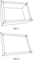
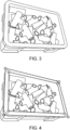
- the information processing device first receives an input of three-dimensional CAD information relating to a three-dimensional model of the container, and analyzes the CAD information. Thereby, by specifying where the upper edge of the three-dimensional model of the container is as shown in Fig. 1 , and then extracting feature points of the upper edge or the like, a two-dimensional template image which is a binarized two-dimensional image showing the shape of the upper edge of the three-dimensional model of the container, as shown in Fig. 2 , is generated.
- the two-dimensional template image generated in this case is equivalent to an upper edge image obtained by capturing an image of the upper edge of the three-dimensional model of the container when a virtual camera and the three-dimensional model of the container are disposed within a virtual space.
- the information processing device extracts feature points including portions other than the upper edge from the three-dimensional model of the container, and then specifies where these feature points are located in a two-dimensional image captured from the virtual camera disposed within the virtual space. Thereby, a correspondence relation between three-dimensional coordinates of the three-dimensional model of the container and two-dimensional coordinates on the two-dimensional image captured by the virtual camera is stored. Meanwhile, the correspondence relation is equivalent to coordinate relationship information to be described later.
- a square container is shown, but there is no limitation thereto, and a round container, a container having partitions therein, or the like can also be considered as a target for processing.
- the information processing device transforms the captured image into a luminance image (or, the input may also be used as a luminance image), and then performs matching with a two-dimensional template generated in advance as shown in Fig. 4 .
- the information processing device can recognize at which position on the captured image (x, y coordinates) and at what rotation angle a container equivalent to a three-dimensional model from which the two-dimensional template is generated is disposed.
- the information processing device specifies the positions of the feature points on the captured image with the matched two-dimensional template as a reference.
- the three-dimensional position/posture of the container is recognized by transforming these positions of feature points using the above-described coordinate relationship information.
- the information processing device 100 generally includes a template generation unit 110, a database (DB) 130, and a recognition unit 150. Meanwhile, each of these configurations may be realized as a program operating on a processor, or may be realized as hardware such as one or a plurality of semiconductors for exclusive use. In addition, the information processing device 100 may also be realized as one computer or the like physically, or may be realized as a plurality of computers or the like physically.
- the template generation unit 110 and the recognition unit 150 can be realized by separate computers. Operations of a hardware configuration or a program in a case where the template generation unit 110 or the recognition unit 150 is realized as a program will be described later with reference to Fig. 9 .
- the template generation unit 110 includes a model input unit 111, a camera parameter input unit 113, an upper edge image generation unit 115, a coordinate relationship information generation unit 117, and an output unit 119.
- the model input unit 111 receives an input of a three-dimensional CAD model of the container.
- each dimension value of the container may be input instead of the three-dimensional CAD model.
- the model input unit 111 is an example of a "first input unit” of the present invention.
- the three-dimensional CAD model and each dimension value of the container are an example of "three-dimensional model information" of the present invention.
- a CAD model of the container in which an input is received by the model input unit 111 or a model of the container which is generated from the dimension values is referred to as a "three-dimensional container model" collectively.
- the camera parameter input unit 113 receives an input of camera parameters relating to a virtual camera that captures an image of three-dimensional container model in a virtual space in which the three-dimensional container model is disposed.
- the camera parameters can include information such as the relative position, direction, or angle of view of the virtual camera for the three-dimensional container model.
- the camera parameters may be set in accordance with the position, direction or the like of an actual environment camera which is disposed in order to capture a luminance image used when the recognition unit 150 recognizes the three-dimensional position/posture of the container.
- the information processing device 100 generates a two-dimensional template 131 by transforming an upper edge image which is a result obtained by capturing an image of the upper edge of the three-dimensional container model using the virtual camera.
- the information processing device 100 matches a captured image (equivalent to a luminance image to be described later) in the actual environment with the two-dimensional template 131 thereon.
- the captured image and the two-dimensional template can be matched using the two-dimensional template generated by the template generation unit 110 as it is.
- the relative position or posture of a camera to a container in the actual environment can be calculated by placing markers with known spacing on a plane where the container is installed, and recognizing the markers on an image captured by an actual environment camera. By using the calculated relative position/posture of the actual environment camera and the three-dimensional model of the container, it is possible to create an image obtained by projecting any plane of a space including the container to the camera.
- the luminance image and/or the two-dimensional template 131 which is input to the recognition unit 150 may be transformed on the basis of relative information on the position of the virtual camera used for the template generation unit 110 to generate the two-dimensional template 131 and the position or angle of the camera used to capture the luminance image which is input to the recognition unit 150. Processing in a case where the luminance image and/or the two-dimensional template 131 is transformed in accordance with the relative relation of the camera will be described later with reference to Fig. 8 .
- the upper edge image generation unit 115 generates an image equivalent to the upper edge of the container (hereinafter referred to as an "upper edge image") in a case where an image of the three-dimensional container model is captured in a virtual space by the virtual camera of which the position or the like is set by camera parameters. More specifically, the upper edge image generation unit 115 first specifies where the upper edge of the three-dimensional container model is according to the normal direction and height of a mesh constituting the three-dimensional container model. For example, among meshes constituting the three-dimensional container model, a portion in which the normal line is directed substantially in a vertical direction (directed at least in an upward direction rather than in a horizontal direction), and which is higher than surrounding meshes can be specified as an upper edge.
- the upper edge image generation unit 115 After the upper edge is specified, the upper edge image generation unit 115 generates an upper edge image which is assumed to be generated in a case where an image of the upper edge is captured from the virtual camera of which the position or the like is specified by camera parameters. An example of generation of the upper edge image is as shown in Fig. 2 .
- the upper edge image generation unit 115 further generates the two-dimensional template 131 for specifying the upper edge from the two-dimensional image captured in the actual environment by performing binarization and edge extraction on the upper edge image according to luminance.
- the two-dimensional template 131 may not necessarily have binarization and edge extraction performed thereon, but it is possible to achieve a decrease in the amount of information of the two-dimensional template 131 by performing such a process and a reduction in the amount of calculation in a matching process using this.
- the upper edge image generation unit 115 is an example of "template generation unit" of the present invention.
- the upper edge image generation unit 115 may transform the two-dimensional template 131 or its original upper edge image in accordance with the direction of the virtual camera specified by camera parameters and/or the direction of the camera used to capture the luminance image in the actual environment.
- the coordinate relationship information generation unit 117 extracts a plurality of feature points from the three-dimensional container model, and then specifies a relationship between three-dimensional coordinates in the virtual space and two-dimensional coordinates on the upper edge image in a case where an image of each of the plurality of feature points of the three-dimensional container model is captured by the virtual camera of which the position or the like is specified by camera parameters.
- the coordinate relationship information generation unit 117 generates coordinate relationship information 133 indicating the specified relationship (relationship between three-dimensional coordinates and two-dimensional coordinates of each feature point).
- the output unit 119 outputs the two-dimensional template 131 generated by the upper edge image generation unit 115 and the coordinate relationship information 133 generated by the coordinate relationship information generation unit 117, as the DB 130, to any storage medium.
- the recognition unit 150 includes a luminance image input unit 151, a template matching unit 153, a feature point coordinate calculation unit 155, a three-dimensional position/posture calculation unit 157, and an output unit 159.
- the luminance image input unit 151 receives an input of a luminance image obtained by capturing an image of a container of which the three-dimensional position/posture is desired to be specified in the actual environment.
- the luminance image input unit 151 is an example of a "second input unit" of the present invention.
- the template matching unit 153 specifies a position equivalent to the upper edge of the container in the luminance image by performing matching with the two-dimensional template 131 on the luminance image which is input from the luminance image input unit 151. Thereby, it is possible to specify at which position (x, y) and at what angle the upper edge of the container is disposed in the luminance image. Meanwhile, in this case, the template matching unit 153 may perform detailed alignment through an iterative closest point (ICP) process after template matching.
- ICP iterative closest point
- the template matching unit 153 is an example of a "matching unit" of the present invention.
- the feature point coordinate calculation unit 155 specifies the positions (coordinates) of the feature points of the container in the luminance image with the position and angle of the upper edge of the container specified by the template matching unit 153 as a reference.
- the three-dimensional position/posture calculation unit 157 obtains the three-dimensional coordinates of each feature point of the container on the basis of the coordinates of the feature points calculated by the feature point coordinate calculation unit 155 and the coordinate relationship information 133. Thereby, the three-dimensional position/posture calculation unit 157 can recognize the position and posture of the container in the real space which is captured in the luminance image.
- the three-dimensional position/posture calculation unit 157 is an example of a "recognition unit" of the present invention.
- the output unit 159 outputs three-dimensional position/posture information indicating the position and posture of the container calculated by the three-dimensional position/posture calculation unit 157. For example, in a case where an industrial robot receives an input of the three-dimensional position/posture information, the position and posture of the container is specified in accordance with the information, and then members placed inside the container can be picked up or the like while control is performed so that its arm does not collide with the container.
- Figs. 6 and 7 are flow charts illustrating a flow of processing of the information processing device 100.
- processing steps to be described later may be executed any modified order or in parallel unless conflict occurs in processing details.
- another step may be added between the processing steps and be executed.
- a step described as one step for convenience may be executed by division into a plurality of steps, and steps described by division into a plurality of steps for convenience may be executed as one step. In this point, the same is true of a flow chart of Fig. 8 to be described later.
- the model input unit 111 of the template generation unit 110 receives an input of the three-dimensional CAD model (S601). As described above, the model input unit 111 may receive an input of dimension values of the containers instead of the three-dimensional CAD model.
- the camera parameter input unit 113 receives an input of camera parameters for determining the position, direction, angle of view, or the like of the virtual camera that captures an image of the three-dimensional container model in order to generate the two-dimensional template 131(S603).
- the upper edge image generation unit 115 first specifies a portion equivalent to an upper edge from the normal direction and height of a mesh constituting the three-dimensional container model with respect to the three-dimensional container model received as an input by the model input unit (S605).
- the upper edge image generation unit 115 can specify, for example, a portion in which the normal line of a mesh constituting the three-dimensional container model is directed at least in an upward direction rather than in a horizontal direction and which is higher than surrounding meshes as an upper edge.
- the upper edge image generation unit 115 generates an upper edge image equivalent to an imaging result in a case where an image of the upper edge of the three-dimensional container model is captured by the virtual camera of which the position or the like is specified by camera parameters (S607).
- the upper edge image generation unit 115 generates the two-dimensional template 131 for detecting the upper edge of the container from the two-dimensional captured image by performing binarization, edge extraction and the like on the upper edge image (S609).
- the coordinate relationship information generation unit 117 extracts a plurality of feature points from the three-dimensional container model, and then generates the coordinate relationship information 133 indicating a relationship between the coordinates of each of the plurality of feature points in a three-dimensional virtual space and the two-dimensional coordinates of the feature point on the upper edge image (S611).
- the output unit 119 outputs the two-dimensional template 131 and the coordinate relationship information 133 which are generated in S609 and S611 to any storage medium (S613).
- the luminance image input unit 151 receives an input of a luminance image obtained by capturing an image of a container (S701).
- the template matching unit 153 specifies the position and rotation angle of the upper edge of the container within the luminance image by matching the luminance image with the two-dimensional template of the container prepared in advance (S703).
- the feature point coordinate calculation unit 155 calculates the two-dimensional coordinates of the feature point of the container in the luminance image with the upper edge of the container specified by the template matching unit 153 as a reference (S705).
- the three-dimensional position/posture calculation unit 157 generates the three-dimensional coordinates of each feature point by transforming the two-dimensional coordinates of each feature point in the luminance image specified in S705 using the coordinate relationship information 133 (S707). Thereby, the three-dimensional position/posture calculation unit 157 recognizes the position and posture of the container in the real space which is captured in the luminance image.
- the output unit 159 outputs position/posture information indicating the calculated position and posture of the container to the outside (S709).
- capturing an image of the three-dimensional container model from directly above using the virtual camera to generate the two-dimensional template, and then performing a recognition process on the luminance image obtained by capturing an image of the container from a direction other than directly above can also be considered. Processing in this case will be described with reference to Fig. 8 .
- the luminance image input unit 151 receives an input of the luminance image obtained by capturing an image of the container (S801).
- the luminance image input unit 151 transforms the input luminance image in accordance with a relative relation (camera external parameters) between the position, direction and the like of the virtual camera used when the two-dimensional template 131 is generated and the position, direction and the like of the camera used to capture the luminance image (S803).
- a relative relation camera external parameters
- plane projective transformation homoography transformation
- the plane projective transformation parameter can be calculated from the virtual camera external parameters.
- the template matching unit 153 performs matching between the input luminance image after the transformation and the two-dimensional template 131 to specify the position and rotation angle of the upper edge of the container within the input image after the transformation (S805).
- the processes of S807 and S809 are the same as the processes of S707 and S709 described with reference to Fig. 7 .
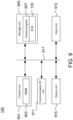
- Fig. 9 schematically illustrates an example of a hardware configuration of the information processing device 100 according to the present embodiment.
- the information processing device 100 shown in the example of Fig. 9 includes a control unit 901, a storage unit 905, a communication interface (I/F) unit 911, an input unit 913, and an output unit 915, and each unit can be selected so as to be capable of communicating with each other through a bus line 917.
- the control unit 901 includes a central processing unit (CPU), a random access memory (RAM) 903, a read only memory (ROM), and the like, and controls each component in accordance with information processing. More specifically, for example, the CPU included in the control unit 901 can execute the above-described various processes relating to the template generation unit 110 and the recognition unit 150 shown in Fig. 5 by reading a control program 907 from the storage unit 905 into the RAM 903 and executing the control program 907.
- CPU central processing unit
- RAM random access memory
- ROM read only memory
- the storage unit 905 is an auxiliary storage device such as, for example, a hard disk drive (HDD) or a solid-state drive (SSD), and stores the control program 907, the database (DB)130 and the like which are executed by the control unit 901.
- DB 130 as described above, it is possible to manage the two-dimensional template 131, the coordinate relationship information 133, or the like. Besides managing information such as camera parameters on the DB 130 can also be considered.
- the control program 907 is a program for executing the processing of the information processing device 100 described with reference to Figs. 1 to 8 . Particularly, the configurations of the template generation unit 110 and the recognition unit 150 shown in Fig. 5 can be realized as the control program 907.
- the communication I/F unit 911 is, for example, a communication module for communicating with another device in a wired or wireless manner.
- Communication systems used for the communication I/F unit 911 to communicate with another device are arbitrary, and examples thereof include a local area network (LAN), a universal serial bus (USB), and the like.
- LAN local area network
- USB universal serial bus
- performing an operation such as outputting the three-dimensional position/posture information to an industrial robot (not shown) through the communication I/F unit 911 can be considered.
- the input unit 913 is, for example, a device for accepting various input operations or the like from a user which are capable of being realized by a mouse, a keyboard, a touch panel, or the like.
- the output unit 915 is, for example, a device, such as a display or a speaker, for informing a user who uses the information processing device 100 of various types of information through display, sound or the like. For example, the output unit 915 displaying the recognition results of the recognition unit 150 for the position/posture of the container to inform a user of the effect can also be considered.
- the information processing device 100 generates, for example, the two-dimensional template which shows the shape of the upper edge of an object to be recognized for posture/position such as the container in advance, and then specifies the position of the container or the like by matching the captured image of an object to be recognized with the two-dimensional template.
- the position and posture of an object to be recognized such as the container are detected by performing a matching process alone on the two-dimensional image in the present embodiment, and thus it is possible to detect the posture/position of an object to be recognized with a high degree of accuracy.
- the outward appearance of the object to be recognized when it is imaged changes depending on whether another member is contained, or the number of members contained, it is difficult to perform detection by matching based on an image of the whole container or the like.
- detection since detection is performed using the image of the upper edge of the container, it is possible to detect the posture/position of an object with a high degree of accuracy regardless of whether a member is contained inside or the like.
- the information processing device 100 since the position and posture of the container is detected on the basis of matching according to the two-dimensional information, it is possible to reduce the amount of calculation more than in a case where the position and posture of the container is detected using the three-dimensional information.
Landscapes
- Engineering & Computer Science (AREA)
- Theoretical Computer Science (AREA)
- Computer Vision & Pattern Recognition (AREA)
- General Physics & Mathematics (AREA)
- Physics & Mathematics (AREA)
- Multimedia (AREA)
- Robotics (AREA)
- Mechanical Engineering (AREA)
- Evolutionary Computation (AREA)
- Software Systems (AREA)
- General Health & Medical Sciences (AREA)
- Databases & Information Systems (AREA)
- Computing Systems (AREA)
- Artificial Intelligence (AREA)
- Health & Medical Sciences (AREA)
- Medical Informatics (AREA)
- Automation & Control Theory (AREA)
- Human Computer Interaction (AREA)
- Image Analysis (AREA)
- Length Measuring Devices By Optical Means (AREA)
- Manipulator (AREA)
Claims (3)
- Informationsverarbeitungsvorrichtung (100), die angepasst ist, ein die dreidimensionale Position und Stellung eines Objekts zu erkennen, umfassend:eine erste Eingabeeinheit (111), die konfiguriert ist, um eine Eingabe einer dreidimensionalen Modellinformation zur Erzeugung eines dreidimensionalen Modells des zu erkennenden Objekts zu empfangen;eine Schablonenerzeugungseinheit (115), die konfiguriert ist, um eine zweidimensionale Schablone (131) zu erzeugen, die eine Form einer oberen Kante des zu erkennenden Objekts basierend auf der dreidimensionalen Modellinformationen zeigt, durch Extrahieren von Merkmalspunkten der oberen Kante von den dreidimensionalen Modellinformationen des zu erkennenden Objekts;eine Koordinatenbeziehungs-Identifikationseinheit (117), die konfiguriert ist, um eine Koordinatenbeziehungsinformation (133) zu erzeugen, die eine Beziehung zwischen dreidimensionalen Koordinaten des dreidimensionalen Modells und zweidimensionalen Koordinaten anzeigt, wenn das dreidimensionale Modell abgebildet wird;eine zweite Eingabeeinheit (151), die konfiguriert ist, um eine Eingabe eines erfassten Bildes zu empfangen, das durch Erfassen eines Bildes des zu erkennenden Objekts erhalten wird;eine Abgleicheinheit (153), die konfiguriert ist, um das erfasste Bild mit der zweidimensionalen Schablone (131) abzugleichen; undeine Erkennungseinheit (157), die konfiguriert ist, um eine dreidimensionale Position und Stellung des zu erkennenden Objekts zu erkennen, durch Bezugnehmen auf die Koordinatenbeziehungsinformationen (133) in Bezug auf das zu erkennende Objekt in dem erfassten Bild, das gemäß den zweidimensionalen Abgleichergebnissen der Abgleicheinheit (153) erfasst wird.
- Informationsverarbeitungsverfahren zum Erkennen der dreidimensionalen Position und Stellung eines Objekts, wobei das Verfahren eine Informationsverarbeitungsvorrichtung (100) veranlasst, auszuführen:einen Prozess des Empfangens einer Eingabe von dreidimensionalen Modellinformationen zum Erzeugen eines dreidimensionalen Modells des zu erkennenden Objekts;einen Prozess des Erzeugens einer zweidimensionalen Schablone (131), die eine Form einer oberen Kante des zu erkennenden Objekts basierend auf dreidimensionalen Modellinformationen zeigt, durch Extrahieren von Merkmalspunkten der oberen Kante aus den dreidimensionalen Modellinformationen des zu erkennenden Objekts;einen Prozess des Erzeugens von Koordinatenbeziehungsinformationen (133), die eine Beziehung zwischen dreidimensionalen Koordinaten des dreidimensionalen Modells und zweidimensionalen Koordinaten anzeigen, wenn das dreidimensionale Modell abgebildet wird;einen Prozess des Empfangens einer Eingabe eines erfassten Bildes, das durch Erfassen eines Bildes des zu erkennenden Objekts erhalten wird;einen Prozess des Abgleichens des erfassten Bildes mit der zweidimensionalen Schablone (131); undeinen Prozess des Erkennens einer dreidimensionalen Position und Stellung des zu erkennenden Objekts in Bezug auf die Koordinatenbeziehungsinformation (133) in Bezug auf das zu erkennende Objekt in dem erfassten Bild, das gemäß zweidimensionalen Abgleichergebnissen erfasst wird.
- Computerprogramm, umfassend Anweisungen, die, wenn das Programm durch eine Informationsverarbeitungsvorrichtung (100) ausgeführt wird, die Informationsverarbeitungsvorrichtung (100) veranlasst, das Verfahren gemäß Anspruch 2 durchzuführen.
Applications Claiming Priority (2)
| Application Number | Priority Date | Filing Date | Title |
|---|---|---|---|
| JP2018046664A JP7161857B2 (ja) | 2018-03-14 | 2018-03-14 | 情報処理装置、情報処理方法、及びプログラム |
| PCT/JP2019/005762 WO2019176450A1 (ja) | 2018-03-14 | 2019-02-18 | 情報処理装置、情報処理方法、及びプログラム |
Publications (3)
| Publication Number | Publication Date |
|---|---|
| EP3767589A1 EP3767589A1 (de) | 2021-01-20 |
| EP3767589A4 EP3767589A4 (de) | 2021-12-15 |
| EP3767589B1 true EP3767589B1 (de) | 2024-11-06 |
Family
ID=67906553
Family Applications (1)
| Application Number | Title | Priority Date | Filing Date |
|---|---|---|---|
| EP19766825.4A Active EP3767589B1 (de) | 2018-03-14 | 2019-02-18 | Informationsverarbeitungsvorrichtung, informationsverarbeitungsverfahren und programm |
Country Status (5)
| Country | Link |
|---|---|
| US (1) | US11823414B2 (de) |
| EP (1) | EP3767589B1 (de) |
| JP (1) | JP7161857B2 (de) |
| CN (1) | CN111742349B (de) |
| WO (1) | WO2019176450A1 (de) |
Families Citing this family (6)
| Publication number | Priority date | Publication date | Assignee | Title |
|---|---|---|---|---|
| JP6796901B1 (ja) * | 2020-03-05 | 2020-12-09 | 株式会社Mujin | 容器検出および物体検出を行うための方法ならびに計算システム |
| TWI903024B (zh) * | 2021-02-18 | 2025-11-01 | 日商發那科股份有限公司 | 機器人系統及控制裝置 |
| JP7570944B2 (ja) * | 2021-02-22 | 2024-10-22 | 株式会社東芝 | 計測システム及び計測プログラム |
| JP7775582B2 (ja) * | 2021-06-22 | 2025-11-26 | コニカミノルタ株式会社 | 対象物認識装置およびプログラム |
| JP7291835B1 (ja) * | 2022-09-13 | 2023-06-15 | 株式会社バンダイ | 画像処理方法、情報処理装置、及び、コンピュータプログラム |
| CN116000937B (zh) * | 2023-01-17 | 2025-08-05 | 杭州申昊科技股份有限公司 | 电力柜按键操作方法、装置、电子设备及可读存储介质 |
Family Cites Families (11)
| Publication number | Priority date | Publication date | Assignee | Title |
|---|---|---|---|---|
| JP5109294B2 (ja) * | 2006-06-19 | 2012-12-26 | 三菱電機株式会社 | 3次元位置補正装置 |
| JP5429614B2 (ja) | 2009-04-16 | 2014-02-26 | 株式会社Ihi | 箱状ワーク認識装置および方法 |
| US20130124156A1 (en) * | 2009-05-26 | 2013-05-16 | Embodee Corp | Footwear digitization system and method |
| JP5469216B2 (ja) * | 2012-07-31 | 2014-04-16 | ファナック株式会社 | バラ積みされた物品をロボットで取出す装置 |
| JP5893695B1 (ja) * | 2014-09-10 | 2016-03-23 | ファナック株式会社 | 物品搬送システム |
| JP6573354B2 (ja) * | 2014-11-28 | 2019-09-11 | キヤノン株式会社 | 画像処理装置、画像処理方法、及びプログラム |
| US10547796B2 (en) * | 2015-07-14 | 2020-01-28 | Industrial Technology Research Institute | Calibration equipment and calibration method of a mechanical system |
| US9804751B2 (en) * | 2015-07-27 | 2017-10-31 | Applied Software Technology, Inc. | Creating and merging two-dimensional floor plans within three-dimensional models |
| JP6356655B2 (ja) * | 2015-12-10 | 2018-07-11 | ファナック株式会社 | 加工屑を除去する機能を有する加工システム |
| US10410089B2 (en) * | 2018-01-19 | 2019-09-10 | Seiko Epson Corporation | Training assistance using synthetic images |
| US10671835B2 (en) * | 2018-03-05 | 2020-06-02 | Hong Kong Applied Science And Technology Research Institute Co., Ltd. | Object recognition |
-
2018
- 2018-03-14 JP JP2018046664A patent/JP7161857B2/ja active Active
-
2019
- 2019-02-18 US US16/975,389 patent/US11823414B2/en active Active
- 2019-02-18 EP EP19766825.4A patent/EP3767589B1/de active Active
- 2019-02-18 CN CN201980012034.3A patent/CN111742349B/zh active Active
- 2019-02-18 WO PCT/JP2019/005762 patent/WO2019176450A1/ja not_active Ceased
Also Published As
| Publication number | Publication date |
|---|---|
| US11823414B2 (en) | 2023-11-21 |
| JP2019159901A (ja) | 2019-09-19 |
| EP3767589A4 (de) | 2021-12-15 |
| EP3767589A1 (de) | 2021-01-20 |
| JP7161857B2 (ja) | 2022-10-27 |
| US20200394818A1 (en) | 2020-12-17 |
| CN111742349A (zh) | 2020-10-02 |
| CN111742349B (zh) | 2023-09-29 |
| WO2019176450A1 (ja) | 2019-09-19 |
Similar Documents
| Publication | Publication Date | Title |
|---|---|---|
| EP3767589B1 (de) | Informationsverarbeitungsvorrichtung, informationsverarbeitungsverfahren und programm | |
| JP6271953B2 (ja) | 画像処理装置、画像処理方法 | |
| US11654571B2 (en) | Three-dimensional data generation device and robot control system | |
| EP3229208B1 (de) | Kamerapositionseinschätzung | |
| KR20160003776A (ko) | 자세 추정 방법 및 로봇 | |
| WO2012008618A1 (en) | Position/orientation measurement apparatus, measurement processing method thereof, and non-transitory computer-readable storage medium | |
| US20180247150A1 (en) | Information processing device, information processing method, and article manufacturing method | |
| JP2016181183A (ja) | 情報処理装置、情報処理方法、プログラム | |
| US11158080B2 (en) | Information processing method, information processing device, object detection apparatus, and robot system | |
| US10708479B2 (en) | Optical measurement of object location in three dimensions | |
| JP6054831B2 (ja) | 画像処理装置、画像処理方法及び画像処理プログラム | |
| US10957067B2 (en) | Control apparatus, object detection system, object detection method and program | |
| JP2011179909A (ja) | 位置姿勢計測装置、位置姿勢計測方法、プログラム | |
| JP2014134856A (ja) | 被写体識別装置、被写体識別方法および被写体識別プログラム | |
| CN113302027B (zh) | 作业坐标生成装置 | |
| Huang et al. | Sensor-aided teleoperated grasping of transparent objects | |
| CN116902467B (zh) | 一种货箱定位方法、装置、设备和存储介质 | |
| JP6040264B2 (ja) | 情報処理装置、情報処理装置の制御方法、およびプログラム | |
| JP2014053018A (ja) | 情報処理装置、情報処理装置の制御方法及びプログラム | |
| Katsoulas et al. | A versatile depalletizer of boxes based on range imagery | |
| CN113554703B (zh) | 机器人定位方法、装置、系统和计算机可读存储介质 | |
| CN115578457A (zh) | 一种应用于无序抓取的动态箱体检测方法 | |
| McAtee et al. | Simulation scan comparison for process monitoring using 3D scanning in manufacturing environments | |
| JP2014235680A (ja) | 画像処理装置、画像処理方法、ロボット及びプログラム | |
| WO2024120172A1 (zh) | 目标物定位方法、装置、设备和存储介质 |
Legal Events
| Date | Code | Title | Description |
|---|---|---|---|
| STAA | Information on the status of an ep patent application or granted ep patent |
Free format text: STATUS: THE INTERNATIONAL PUBLICATION HAS BEEN MADE |
|
| PUAI | Public reference made under article 153(3) epc to a published international application that has entered the european phase |
Free format text: ORIGINAL CODE: 0009012 |
|
| STAA | Information on the status of an ep patent application or granted ep patent |
Free format text: STATUS: REQUEST FOR EXAMINATION WAS MADE |
|
| 17P | Request for examination filed |
Effective date: 20200907 |
|
| AK | Designated contracting states |
Kind code of ref document: A1 Designated state(s): AL AT BE BG CH CY CZ DE DK EE ES FI FR GB GR HR HU IE IS IT LI LT LU LV MC MK MT NL NO PL PT RO RS SE SI SK SM TR |
|
| AX | Request for extension of the european patent |
Extension state: BA ME |
|
| DAV | Request for validation of the european patent (deleted) | ||
| DAX | Request for extension of the european patent (deleted) | ||
| A4 | Supplementary search report drawn up and despatched |
Effective date: 20211115 |
|
| RIC1 | Information provided on ipc code assigned before grant |
Ipc: G06T 7/70 20170101AFI20211109BHEP |
|
| GRAP | Despatch of communication of intention to grant a patent |
Free format text: ORIGINAL CODE: EPIDOSNIGR1 |
|
| STAA | Information on the status of an ep patent application or granted ep patent |
Free format text: STATUS: GRANT OF PATENT IS INTENDED |
|
| INTG | Intention to grant announced |
Effective date: 20240620 |
|
| GRAS | Grant fee paid |
Free format text: ORIGINAL CODE: EPIDOSNIGR3 |
|
| GRAA | (expected) grant |
Free format text: ORIGINAL CODE: 0009210 |
|
| STAA | Information on the status of an ep patent application or granted ep patent |
Free format text: STATUS: THE PATENT HAS BEEN GRANTED |
|
| AK | Designated contracting states |
Kind code of ref document: B1 Designated state(s): AL AT BE BG CH CY CZ DE DK EE ES FI FR GB GR HR HU IE IS IT LI LT LU LV MC MK MT NL NO PL PT RO RS SE SI SK SM TR |
|
| REG | Reference to a national code |
Ref country code: GB Ref legal event code: FG4D |
|
| REG | Reference to a national code |
Ref country code: CH Ref legal event code: EP |
|
| REG | Reference to a national code |
Ref country code: DE Ref legal event code: R096 Ref document number: 602019061534 Country of ref document: DE |
|
| REG | Reference to a national code |
Ref country code: IE Ref legal event code: FG4D |
|
| REG | Reference to a national code |
Ref country code: LT Ref legal event code: MG9D |
|
| REG | Reference to a national code |
Ref country code: NL Ref legal event code: MP Effective date: 20241106 |
|
| PG25 | Lapsed in a contracting state [announced via postgrant information from national office to epo] |
Ref country code: HR Free format text: LAPSE BECAUSE OF FAILURE TO SUBMIT A TRANSLATION OF THE DESCRIPTION OR TO PAY THE FEE WITHIN THE PRESCRIBED TIME-LIMIT Effective date: 20241106 Ref country code: IS Free format text: LAPSE BECAUSE OF FAILURE TO SUBMIT A TRANSLATION OF THE DESCRIPTION OR TO PAY THE FEE WITHIN THE PRESCRIBED TIME-LIMIT Effective date: 20250306 Ref country code: PT Free format text: LAPSE BECAUSE OF FAILURE TO SUBMIT A TRANSLATION OF THE DESCRIPTION OR TO PAY THE FEE WITHIN THE PRESCRIBED TIME-LIMIT Effective date: 20250306 |
|
| PG25 | Lapsed in a contracting state [announced via postgrant information from national office to epo] |
Ref country code: NL Free format text: LAPSE BECAUSE OF FAILURE TO SUBMIT A TRANSLATION OF THE DESCRIPTION OR TO PAY THE FEE WITHIN THE PRESCRIBED TIME-LIMIT Effective date: 20241106 Ref country code: FI Free format text: LAPSE BECAUSE OF FAILURE TO SUBMIT A TRANSLATION OF THE DESCRIPTION OR TO PAY THE FEE WITHIN THE PRESCRIBED TIME-LIMIT Effective date: 20241106 |
|
| REG | Reference to a national code |
Ref country code: AT Ref legal event code: MK05 Ref document number: 1740218 Country of ref document: AT Kind code of ref document: T Effective date: 20241106 |
|
| PG25 | Lapsed in a contracting state [announced via postgrant information from national office to epo] |
Ref country code: BG Free format text: LAPSE BECAUSE OF FAILURE TO SUBMIT A TRANSLATION OF THE DESCRIPTION OR TO PAY THE FEE WITHIN THE PRESCRIBED TIME-LIMIT Effective date: 20241106 |
|
| PG25 | Lapsed in a contracting state [announced via postgrant information from national office to epo] |
Ref country code: ES Free format text: LAPSE BECAUSE OF FAILURE TO SUBMIT A TRANSLATION OF THE DESCRIPTION OR TO PAY THE FEE WITHIN THE PRESCRIBED TIME-LIMIT Effective date: 20241106 |
|
| PG25 | Lapsed in a contracting state [announced via postgrant information from national office to epo] |
Ref country code: NO Free format text: LAPSE BECAUSE OF FAILURE TO SUBMIT A TRANSLATION OF THE DESCRIPTION OR TO PAY THE FEE WITHIN THE PRESCRIBED TIME-LIMIT Effective date: 20250206 |
|
| PG25 | Lapsed in a contracting state [announced via postgrant information from national office to epo] |
Ref country code: LV Free format text: LAPSE BECAUSE OF FAILURE TO SUBMIT A TRANSLATION OF THE DESCRIPTION OR TO PAY THE FEE WITHIN THE PRESCRIBED TIME-LIMIT Effective date: 20241106 Ref country code: GR Free format text: LAPSE BECAUSE OF FAILURE TO SUBMIT A TRANSLATION OF THE DESCRIPTION OR TO PAY THE FEE WITHIN THE PRESCRIBED TIME-LIMIT Effective date: 20250207 Ref country code: AT Free format text: LAPSE BECAUSE OF FAILURE TO SUBMIT A TRANSLATION OF THE DESCRIPTION OR TO PAY THE FEE WITHIN THE PRESCRIBED TIME-LIMIT Effective date: 20241106 |
|
| PG25 | Lapsed in a contracting state [announced via postgrant information from national office to epo] |
Ref country code: PL Free format text: LAPSE BECAUSE OF FAILURE TO SUBMIT A TRANSLATION OF THE DESCRIPTION OR TO PAY THE FEE WITHIN THE PRESCRIBED TIME-LIMIT Effective date: 20241106 |
|
| PG25 | Lapsed in a contracting state [announced via postgrant information from national office to epo] |
Ref country code: RS Free format text: LAPSE BECAUSE OF FAILURE TO SUBMIT A TRANSLATION OF THE DESCRIPTION OR TO PAY THE FEE WITHIN THE PRESCRIBED TIME-LIMIT Effective date: 20250206 |
|
| PG25 | Lapsed in a contracting state [announced via postgrant information from national office to epo] |
Ref country code: SM Free format text: LAPSE BECAUSE OF FAILURE TO SUBMIT A TRANSLATION OF THE DESCRIPTION OR TO PAY THE FEE WITHIN THE PRESCRIBED TIME-LIMIT Effective date: 20241106 |
|
| PG25 | Lapsed in a contracting state [announced via postgrant information from national office to epo] |
Ref country code: DK Free format text: LAPSE BECAUSE OF FAILURE TO SUBMIT A TRANSLATION OF THE DESCRIPTION OR TO PAY THE FEE WITHIN THE PRESCRIBED TIME-LIMIT Effective date: 20241106 |
|
| PG25 | Lapsed in a contracting state [announced via postgrant information from national office to epo] |
Ref country code: EE Free format text: LAPSE BECAUSE OF FAILURE TO SUBMIT A TRANSLATION OF THE DESCRIPTION OR TO PAY THE FEE WITHIN THE PRESCRIBED TIME-LIMIT Effective date: 20241106 |
|
| PG25 | Lapsed in a contracting state [announced via postgrant information from national office to epo] |
Ref country code: RO Free format text: LAPSE BECAUSE OF FAILURE TO SUBMIT A TRANSLATION OF THE DESCRIPTION OR TO PAY THE FEE WITHIN THE PRESCRIBED TIME-LIMIT Effective date: 20241106 |
|
| PG25 | Lapsed in a contracting state [announced via postgrant information from national office to epo] |
Ref country code: SK Free format text: LAPSE BECAUSE OF FAILURE TO SUBMIT A TRANSLATION OF THE DESCRIPTION OR TO PAY THE FEE WITHIN THE PRESCRIBED TIME-LIMIT Effective date: 20241106 |
|
| PG25 | Lapsed in a contracting state [announced via postgrant information from national office to epo] |
Ref country code: CZ Free format text: LAPSE BECAUSE OF FAILURE TO SUBMIT A TRANSLATION OF THE DESCRIPTION OR TO PAY THE FEE WITHIN THE PRESCRIBED TIME-LIMIT Effective date: 20241106 |
|
| PG25 | Lapsed in a contracting state [announced via postgrant information from national office to epo] |
Ref country code: IT Free format text: LAPSE BECAUSE OF FAILURE TO SUBMIT A TRANSLATION OF THE DESCRIPTION OR TO PAY THE FEE WITHIN THE PRESCRIBED TIME-LIMIT Effective date: 20241106 |
|
| REG | Reference to a national code |
Ref country code: DE Ref legal event code: R097 Ref document number: 602019061534 Country of ref document: DE |
|
| PG25 | Lapsed in a contracting state [announced via postgrant information from national office to epo] |
Ref country code: SE Free format text: LAPSE BECAUSE OF FAILURE TO SUBMIT A TRANSLATION OF THE DESCRIPTION OR TO PAY THE FEE WITHIN THE PRESCRIBED TIME-LIMIT Effective date: 20241106 |
|
| PLBE | No opposition filed within time limit |
Free format text: ORIGINAL CODE: 0009261 |
|
| STAA | Information on the status of an ep patent application or granted ep patent |
Free format text: STATUS: NO OPPOSITION FILED WITHIN TIME LIMIT |
|
| PG25 | Lapsed in a contracting state [announced via postgrant information from national office to epo] |
Ref country code: MC Free format text: LAPSE BECAUSE OF FAILURE TO SUBMIT A TRANSLATION OF THE DESCRIPTION OR TO PAY THE FEE WITHIN THE PRESCRIBED TIME-LIMIT Effective date: 20241106 |
|
| REG | Reference to a national code |
Ref country code: CH Ref legal event code: PL |
|
| 26N | No opposition filed |
Effective date: 20250807 |
|
| PG25 | Lapsed in a contracting state [announced via postgrant information from national office to epo] |
Ref country code: LU Free format text: LAPSE BECAUSE OF NON-PAYMENT OF DUE FEES Effective date: 20250218 |
|
| PG25 | Lapsed in a contracting state [announced via postgrant information from national office to epo] |
Ref country code: CH Free format text: LAPSE BECAUSE OF NON-PAYMENT OF DUE FEES Effective date: 20250228 |
|
| GBPC | Gb: european patent ceased through non-payment of renewal fee |
Effective date: 20250218 |
|
| REG | Reference to a national code |
Ref country code: BE Ref legal event code: MM Effective date: 20250228 |
|
| PG25 | Lapsed in a contracting state [announced via postgrant information from national office to epo] |
Ref country code: GB Free format text: LAPSE BECAUSE OF NON-PAYMENT OF DUE FEES Effective date: 20250218 |
|
| PG25 | Lapsed in a contracting state [announced via postgrant information from national office to epo] |
Ref country code: FR Free format text: LAPSE BECAUSE OF NON-PAYMENT OF DUE FEES Effective date: 20250228 |
|
| PG25 | Lapsed in a contracting state [announced via postgrant information from national office to epo] |
Ref country code: BE Free format text: LAPSE BECAUSE OF NON-PAYMENT OF DUE FEES Effective date: 20250228 |
|
| PG25 | Lapsed in a contracting state [announced via postgrant information from national office to epo] |
Ref country code: IE Free format text: LAPSE BECAUSE OF NON-PAYMENT OF DUE FEES Effective date: 20250218 |
|
| PGFP | Annual fee paid to national office [announced via postgrant information from national office to epo] |
Ref country code: DE Payment date: 20260217 Year of fee payment: 8 |