US9508246B2 - In-vehicle charging device, automobile and charging system - Google Patents
In-vehicle charging device, automobile and charging system Download PDFInfo
- Publication number
- US9508246B2 US9508246B2 US14/417,316 US201314417316A US9508246B2 US 9508246 B2 US9508246 B2 US 9508246B2 US 201314417316 A US201314417316 A US 201314417316A US 9508246 B2 US9508246 B2 US 9508246B2
- Authority
- US
- United States
- Prior art keywords
- mobile device
- vehicle
- charging
- seating position
- charging coil
- Prior art date
- Legal status (The legal status is an assumption and is not a legal conclusion. Google has not performed a legal analysis and makes no representation as to the accuracy of the status listed.)
- Active, expires
Links
- 108010066114 cabin-2 Proteins 0.000 description 10
- 238000010586 diagram Methods 0.000 description 2
- 238000012986 modification Methods 0.000 description 1
- 230000004048 modification Effects 0.000 description 1
Images


Classifications
-
- H—ELECTRICITY
- H02—GENERATION; CONVERSION OR DISTRIBUTION OF ELECTRIC POWER
- H02J—CIRCUIT ARRANGEMENTS OR SYSTEMS FOR SUPPLYING OR DISTRIBUTING ELECTRIC POWER; SYSTEMS FOR STORING ELECTRIC ENERGY
- H02J50/00—Circuit arrangements or systems for wireless supply or distribution of electric power
- H02J50/40—Circuit arrangements or systems for wireless supply or distribution of electric power using two or more transmitting or receiving devices
-
- G—PHYSICS
- G08—SIGNALLING
- G08B—SIGNALLING OR CALLING SYSTEMS; ORDER TELEGRAPHS; ALARM SYSTEMS
- G08B21/00—Alarms responsive to a single specified undesired or abnormal condition and not otherwise provided for
- G08B21/18—Status alarms
- G08B21/24—Reminder alarms, e.g. anti-loss alarms
-
- B—PERFORMING OPERATIONS; TRANSPORTING
- B60—VEHICLES IN GENERAL
- B60R—VEHICLES, VEHICLE FITTINGS, OR VEHICLE PARTS, NOT OTHERWISE PROVIDED FOR
- B60R25/00—Fittings or systems for preventing or indicating unauthorised use or theft of vehicles
- B60R25/40—Features of the power supply for the anti-theft system, e.g. anti-theft batteries, back-up power supply or means to save battery power
- B60R25/406—Power supply in the remote key
-
- H02J17/00—
-
- H—ELECTRICITY
- H02—GENERATION; CONVERSION OR DISTRIBUTION OF ELECTRIC POWER
- H02J—CIRCUIT ARRANGEMENTS OR SYSTEMS FOR SUPPLYING OR DISTRIBUTING ELECTRIC POWER; SYSTEMS FOR STORING ELECTRIC ENERGY
- H02J50/00—Circuit arrangements or systems for wireless supply or distribution of electric power
- H02J50/10—Circuit arrangements or systems for wireless supply or distribution of electric power using inductive coupling
-
- H—ELECTRICITY
- H02—GENERATION; CONVERSION OR DISTRIBUTION OF ELECTRIC POWER
- H02J—CIRCUIT ARRANGEMENTS OR SYSTEMS FOR SUPPLYING OR DISTRIBUTING ELECTRIC POWER; SYSTEMS FOR STORING ELECTRIC ENERGY
- H02J50/00—Circuit arrangements or systems for wireless supply or distribution of electric power
- H02J50/80—Circuit arrangements or systems for wireless supply or distribution of electric power involving the exchange of data, concerning supply or distribution of electric power, between transmitting devices and receiving devices
-
- H—ELECTRICITY
- H02—GENERATION; CONVERSION OR DISTRIBUTION OF ELECTRIC POWER
- H02J—CIRCUIT ARRANGEMENTS OR SYSTEMS FOR SUPPLYING OR DISTRIBUTING ELECTRIC POWER; SYSTEMS FOR STORING ELECTRIC ENERGY
- H02J7/00—Circuit arrangements for charging or depolarising batteries or for supplying loads from batteries
- H02J7/00032—Circuit arrangements for charging or depolarising batteries or for supplying loads from batteries characterised by data exchange
- H02J7/00036—Charger exchanging data with battery
-
- H02J7/0004—
-
- H04W4/008—
-
- H—ELECTRICITY
- H04—ELECTRIC COMMUNICATION TECHNIQUE
- H04W—WIRELESS COMMUNICATION NETWORKS
- H04W4/00—Services specially adapted for wireless communication networks; Facilities therefor
- H04W4/80—Services using short range communication, e.g. near-field communication [NFC], radio-frequency identification [RFID] or low energy communication
-
- H—ELECTRICITY
- H02—GENERATION; CONVERSION OR DISTRIBUTION OF ELECTRIC POWER
- H02J—CIRCUIT ARRANGEMENTS OR SYSTEMS FOR SUPPLYING OR DISTRIBUTING ELECTRIC POWER; SYSTEMS FOR STORING ELECTRIC ENERGY
- H02J50/00—Circuit arrangements or systems for wireless supply or distribution of electric power
- H02J50/005—Mechanical details of housing or structure aiming to accommodate the power transfer means, e.g. mechanical integration of coils, antennas or transducers into emitting or receiving devices
-
- H02J7/025—
Definitions
- the present invention relates to an in-vehicle charging device which charges a mobile device such as a mobile telephone in a non-contact manner, an automobile, and a charging system.
- An in-vehicle charging device includes a charging coil for charging a rechargeable battery of a mobile device such as a mobile telephone, and a charge controller which is connected to the charging coil, and performs non-contact charging of the rechargeable battery of the mobile device in a vehicle (for example, see Patent Literature 1).
- the above-described in-vehicle charging device In an automobile in which the above-described in-vehicle charging device is disposed, not only the driver, but also another person who is in the automobile can cause a mobile device to be charged. In addition to a mobile device of the driver of a taxi, for example, also that of a passenger in the taxi can be charged. In the case where the passenger is unaccustomed to cause the mobile device to be charged by using such an in-vehicle charging device, particularly, the passenger may forget that the own mobile device is being charged, and get off the taxi while leaving the mobile device in the taxi.
- the invention provides an in-vehicle charging device which includes: a charging coil that charges a rechargeable battery of a mobile device; a charge controller that is connected to the charging coil; and a first short-range wireless communicating section that is connected to the charge controller, wherein, during charging of the rechargeable battery of the mobile device by the charging coil, the charge controller acquires information of a seating position of an owner of the mobile device, through the first short-range wireless communicating section, and outputs the seating position information from an external outputting section that is connected to the charge controller.
- the in-vehicle charging device of the invention includes: a charging coil that charges a rechargeable battery of a mobile device; a charge controller that is connected to the charging coil; and a first short-range wireless communicating section that is connected to the charge controller, and, during charging of the rechargeable battery of the mobile device by the charging coil, the charge controller acquires information of a seating position of an owner of the mobile device, through the first short-range wireless communicating section, and outputs the seating position information from an external outputting section that is connected to the charge controller. Therefore, it is possible to prevent the mobile device from being left in a vehicle.
- the charge controller acquires information of the seating position of the owner of the mobile device, through the first short-range wireless communicating section, and therefore can issue an alarm based on an operation of leaving from the seating position. As a result, it is possible to prevent the mobile device from being left in a vehicle.
- FIG. 1 is a perspective view showing an automobile in which an in-vehicle charging device of an embodiment is mounted.
- FIG. 2 is a top view showing the interior of the automobile shown in FIG. 1 .
- FIG. 3 is a front view of the in-vehicle charging device disposed in the automobile shown in FIG. 1 .
- FIG. 4 is a block diagram of a charging system which is constructed in the automobile shown in FIG. 1 .
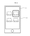
- FIG. 5 is a front view of a mobile device in which a seating position of a passenger is displayed on a display.
- FIG. 6 is a flowchart showing the operation of the mobile device.
- FIG. 7 is a flowchart showing the operation of the charging system which is constructed in the automobile.
- FIG. 1 is a perspective view showing an automobile in which an in-vehicle charging device of the embodiment is mounted.
- FIG. 2 is a top view showing the interior of the automobile shown in FIG. 1 .
- a steering wheel 3 is placed in the front side of the cabin 2 .
- a driver seat 4 in the rear of the steering wheel 3 in the cabin 2 , a driver seat 4 , a front passenger seat 5 , and rear passenger seats 6 , 7 are disposed.
- an in-vehicle charging device 8 is disposed between the steering wheel 3 , and the driver seat 4 and the front passenger seat 5 , and between the driver seat 4 and the front passenger seat 5 .
- a door 9 is disposed in the outer portion of the driver seat 4 in the automobile body 1 , so that the driver is enabled to get in or out of the cabin 2 by opening the door 9 .
- a door 10 is disposed in the outer portion of the front passenger seat 5 in the automobile body 1 , so that the passenger to sit on the front passenger seat 5 is enabled to get in or out of the cabin 2 by opening the door 10 .
- a door 11 is disposed in the outer portion of the rear passenger seat 6 in the automobile body 1 , so that the passenger to sit on the rear passenger seat 6 is enabled to get in or out of the cabin 2 by opening the door 11 .
- a door 12 is disposed in the outer portion of the rear passenger seat 7 in the automobile body 1 , so that the passenger to sit on the rear passenger seat 7 is enabled to get in or out of the cabin 2 by opening the door 12 .
- tags 13 , 14 , 15 , 16 which serve as a seating position setting section are disposed in opening/closing knobs (not shown) of the outer surfaces of the doors 9 to 12 .
- an in-vehicle electronic apparatus 17 for navigation and AV reproduction is disposed on a lateral side of the steering wheel 3 in the cabin 2 .
- the in-vehicle electronic apparatus 17 has a display 18 , an image processing section 19 , an audio outputting section 20 , and a controller 21 for them.
- a speaker 22 which serves also as an alarm outputting section is connected to the audio outputting section 20 .
- FIG. 3 is a front view of the in-vehicle electronic apparatus 17 .
- FIG. 4 is a block diagram of a charging system which is constructed in the automobile.
- the in-vehicle charging device 8 includes a charging coil 24 , a charge driving circuit 25 , a charge controller 26 , and a short-range wireless communicating section (hereinafter, referred to as “NFC communicating section”) 27 .
- the charging coil 24 charges a rechargeable battery 33 of a mobile device 23 shown in FIG. 4 .
- the charge controller 26 is connected to the charging coil 24 through the charge driving circuit 25 .
- the NFC communicating section 27 is connected to the charge controller 26 .
- the charge controller 26 is connected also to a vehicle controller 28 .
- the vehicle controller 28 is connected to the controller 21 of the in-vehicle electronic apparatus 17 , and also to a seat belt detector 29 and weight detector 30 which are placed as a seating detector in each of the driver seat 4 , the front passenger seat 5 , and the rear passenger seats 6 , 7 .
- the mobile device 23 includes a charging coil 31 , a controller 32 which is connected to the charging coil 31 , the rechargeable battery 33 , a display 34 which is connected to the controller 32 , an operating section 35 , an image processing section 36 , a memory 37 , and an NFC communicating section 38 .
- the NFC communicating section 38 is connected to the controller 32 .
- the person who carries the mobile device 23 opens one of the doors 9 to 12 and gets in the cabin 2 , the person passes the mobile device 23 over the tag ( 13 to 16 ) which is disposed as the seating position setting section in the opening/closing knob (not shown) of the outer surface of the opened door (S 101 of FIG. 6 ). Namely, the person causes the mobile device 23 to approach the tag. Then, the seating position (the driver seat 4 , the front passenger seat 5 , the rear passenger seat 6 , or the rear passenger seat 7 ) of the person is read through the NFC communicating section 38 of the mobile device 23 shown in FIG. 4 , and recorded as seating position information in the memory 37 (S 102 of FIG. 6 ). As shown in FIG. 5 , moreover, the seating position of the person in the cabin 2 is displayed on the display 34 of the mobile device 23 .
- the driver operates the ignition switch of the automobile to turn ON the ACC power supply (S 1 of FIG. 7 ).
- the in-vehicle charging device 8 is activated (S 2 of FIG. 7 ), and the activated state is kept held unless a power supply switch (not shown) of the in-vehicle charging device 8 is turned OFF (S 3 of FIG. 7 ).
- the charging coil 24 of the in-vehicle charging device 8 and the charging coil 31 of the mobile device 23 are opposed to each other as shown in FIG. 4 .
- the impedance of the charging coil 24 of the in-vehicle charging device 8 is changed, and therefore the charge controller 26 recognizes that the mobile device 23 is attached.
- the NFC communicating section 27 of the in-vehicle charging device 8 , and the NFC communicating section 38 of the mobile device 23 are approximated and opposed to each other. Therefore, the seating position information (in this case, information indicative of the rear passenger seat 7 ) recorded in the memory 37 of the mobile device 23 is transmitted to the charge controller 26 of the in-vehicle charging device 8 , and then to the vehicle controller 28 (S 4 and S 5 of FIG. 7 ).
- the rechargeable battery 33 of the mobile device 23 is charged in a non-contact manner by the charging coil 24 of the in-vehicle charging device 8 (S 6 of FIG. 7 ).
- the seat belt detector 29 and weight detector 30 which are used as the seating detector detect that a person is sitting on the rear passenger seat 7 (S 7 of FIG. 7 ).
- the vehicle controller 28 controls the in-vehicle electronic apparatus 17 through the controller 21 so as to output an alarm from the speaker 22 (S 11 of FIG. 7 ).
- the situation where the mobile device 23 remains to be attached to the in-vehicle charging device 8 is notified not only to the person who has sat on the rear passenger seat 7 , but also to the driver and a fellow passenger(s). As a result, it is possible to prevent the mobile device 23 from being left.
- the vehicle controller 28 controls the in-vehicle electronic apparatus 17 through the controller 21 so as to output the alarm from the speaker 22 (S 12 of FIG. 7 ).
- the control of the output of the alarm from the speaker 22 may be performed by the charge controller 26 of the in-vehicle charging device 8 through the controller 21 of the in-vehicle electronic apparatus 17 . In this case, however, the information output from the seat belt detector 29 and the weight detector 30 must be transmitted from the vehicle controller 28 to the charge controller 26 .
- the charge controller acquires the information of the seating position of the owner of the mobile device, through the NFC communicating section, and therefore can issue an alarm based on an operation of leaving from the seating position. As a result, it is possible to prevent the mobile device from being left in the vehicle.
- the invention is useful as an in-vehicle charging device or the like.
Landscapes
- Engineering & Computer Science (AREA)
- Power Engineering (AREA)
- Computer Networks & Wireless Communication (AREA)
- Mechanical Engineering (AREA)
- Signal Processing (AREA)
- Business, Economics & Management (AREA)
- Emergency Management (AREA)
- Physics & Mathematics (AREA)
- General Physics & Mathematics (AREA)
- Charge And Discharge Circuits For Batteries Or The Like (AREA)
Applications Claiming Priority (3)
| Application Number | Priority Date | Filing Date | Title |
|---|---|---|---|
| JP2012166770 | 2012-07-27 | ||
| JP2012-166770 | 2012-07-27 | ||
| PCT/JP2013/004540 WO2014017099A1 (ja) | 2012-07-27 | 2013-07-25 | 車載用充電装置、自動車及び充電システム |
Publications (2)
| Publication Number | Publication Date |
|---|---|
| US20150248830A1 US20150248830A1 (en) | 2015-09-03 |
| US9508246B2 true US9508246B2 (en) | 2016-11-29 |
Family
ID=49996924
Family Applications (1)
| Application Number | Title | Priority Date | Filing Date |
|---|---|---|---|
| US14/417,316 Active 2033-08-27 US9508246B2 (en) | 2012-07-27 | 2013-07-25 | In-vehicle charging device, automobile and charging system |
Country Status (5)
| Country | Link |
|---|---|
| US (1) | US9508246B2 (zh) |
| EP (1) | EP2879271B1 (zh) |
| JP (1) | JP6277492B2 (zh) |
| CN (1) | CN104507763B (zh) |
| WO (1) | WO2014017099A1 (zh) |
Cited By (2)
| Publication number | Priority date | Publication date | Assignee | Title |
|---|---|---|---|---|
| US10266148B2 (en) * | 2016-07-26 | 2019-04-23 | Volkswagen Ag | Method, computer program and apparatus for verifying authorization of a mobile communication device |
| US11233541B2 (en) * | 2020-03-31 | 2022-01-25 | Panasonic Intellectual Property Management Co., Ltd. | Communication control device, communication control system, and communication control method |
Families Citing this family (9)
| Publication number | Priority date | Publication date | Assignee | Title |
|---|---|---|---|---|
| US9805580B2 (en) * | 2015-01-23 | 2017-10-31 | Visteon Global Technologies, Inc. | Initiating an alert based on a mobile device being left behind |
| US9598008B2 (en) * | 2015-07-23 | 2017-03-21 | GM Global Technology Operations LLC | Phone left in bin notification system and method |
| KR102039662B1 (ko) * | 2017-05-26 | 2019-11-04 | 김영조 | 건전지 대용 무선배터리팩 장치 |
| CN108844547A (zh) * | 2018-04-23 | 2018-11-20 | 山东理工大学 | 一种电动汽车主动充电预警方法及系统 |
| CN111098797A (zh) * | 2018-10-25 | 2020-05-05 | 上海博泰悦臻电子设备制造有限公司 | 一种车载装置及车辆 |
| JP2020142570A (ja) * | 2019-03-04 | 2020-09-10 | テイ・エス テック株式会社 | 通知システム及び通知システムを備える車両 |
| CN113838273B (zh) * | 2021-09-06 | 2023-08-18 | 阿波罗智联(北京)科技有限公司 | 基于车辆的提醒方法、装置、电子设备和存储介质 |
| CN113911157A (zh) * | 2021-10-21 | 2022-01-11 | 深圳市怡华兴电子有限公司 | 一种应用于轨道车辆的移动设备充电保护装置 |
| CN116110206A (zh) * | 2023-01-18 | 2023-05-12 | 重庆赛力斯新能源汽车设计院有限公司 | 终端遗忘车内的提醒方法和装置、电子设备和存储介质 |
Citations (11)
| Publication number | Priority date | Publication date | Assignee | Title |
|---|---|---|---|---|
| US20060290319A1 (en) | 2005-06-27 | 2006-12-28 | Burgan John M | Method and apparatus for reminding a user of an unattended device in a vehicle |
| JP2007104868A (ja) | 2005-10-07 | 2007-04-19 | Toyota Motor Corp | 車両用充電装置、電気機器及び車両用非接触充電システム |
| JP2009296780A (ja) | 2008-06-04 | 2009-12-17 | Kojima Press Industry Co Ltd | 車載充電器 |
| JP2010028936A (ja) | 2008-07-16 | 2010-02-04 | Seiko Epson Corp | 送電制御装置、送電装置、受電制御装置、受電装置及び電子機器 |
| US20110018498A1 (en) * | 2007-12-21 | 2011-01-27 | Soar Roger J | Vehicle seat inductive charger and data transmitter |
| JP2011036125A (ja) | 2005-05-09 | 2011-02-17 | Sony Corp | 非接触充電装置及び非接触充電システム並びに非接触充電方法 |
| US20110137773A1 (en) | 2009-12-08 | 2011-06-09 | At&T Mobility Ii Llc | Devices, Systems and Methods for Identifying and/or Billing an Individual in a Vehicle |
| JP2012070565A (ja) | 2010-09-24 | 2012-04-05 | Fujitsu Ltd | 電気自動車、充電ステーション及びこれらのプログラム |
| US20130249482A1 (en) * | 2011-04-22 | 2013-09-26 | Panasonic Corporation | Vehicle-mounting charging apparatus and vehicle mounted therewith |
| US20130249682A1 (en) * | 2011-10-27 | 2013-09-26 | Ford Global Technologies, Llc | Vehicle wireless charger safety system |
| US20150380975A1 (en) * | 2014-06-25 | 2015-12-31 | Honda Motor Co., Ltd. | Wireless charging system |
Family Cites Families (6)
| Publication number | Priority date | Publication date | Assignee | Title |
|---|---|---|---|---|
| JP4619136B2 (ja) * | 2005-01-17 | 2011-01-26 | アルパイン株式会社 | 個人所有物の置き忘れ防止装置および置き忘れ警告方法 |
| JP2007016518A (ja) * | 2005-07-08 | 2007-01-25 | Mitsubishi Electric Corp | 車両用通信装置 |
| JP2007174823A (ja) * | 2005-12-22 | 2007-07-05 | Kyasutekku:Kk | 携帯電話機用充電器 |
| JP5362330B2 (ja) | 2007-12-18 | 2013-12-11 | 三洋電機株式会社 | 充電台 |
| JP2009299262A (ja) * | 2008-06-10 | 2009-12-24 | Omron Corp | 通信システム及び通信方法 |
| JP5476973B2 (ja) * | 2009-12-17 | 2014-04-23 | 株式会社デンソー | 車両用充電システム |
-
2013
- 2013-07-25 WO PCT/JP2013/004540 patent/WO2014017099A1/ja active Application Filing
- 2013-07-25 CN CN201380039865.2A patent/CN104507763B/zh active Active
- 2013-07-25 EP EP13823089.1A patent/EP2879271B1/en active Active
- 2013-07-25 US US14/417,316 patent/US9508246B2/en active Active
- 2013-07-25 JP JP2014526775A patent/JP6277492B2/ja not_active Expired - Fee Related
Patent Citations (12)
| Publication number | Priority date | Publication date | Assignee | Title |
|---|---|---|---|---|
| JP2011036125A (ja) | 2005-05-09 | 2011-02-17 | Sony Corp | 非接触充電装置及び非接触充電システム並びに非接触充電方法 |
| US20060290319A1 (en) | 2005-06-27 | 2006-12-28 | Burgan John M | Method and apparatus for reminding a user of an unattended device in a vehicle |
| CN101208823A (zh) | 2005-06-27 | 2008-06-25 | 摩托罗拉公司 | 用于提醒用户交通工具中无人看管的设备的方法和装置 |
| JP2007104868A (ja) | 2005-10-07 | 2007-04-19 | Toyota Motor Corp | 車両用充電装置、電気機器及び車両用非接触充電システム |
| US20110018498A1 (en) * | 2007-12-21 | 2011-01-27 | Soar Roger J | Vehicle seat inductive charger and data transmitter |
| JP2009296780A (ja) | 2008-06-04 | 2009-12-17 | Kojima Press Industry Co Ltd | 車載充電器 |
| JP2010028936A (ja) | 2008-07-16 | 2010-02-04 | Seiko Epson Corp | 送電制御装置、送電装置、受電制御装置、受電装置及び電子機器 |
| US20110137773A1 (en) | 2009-12-08 | 2011-06-09 | At&T Mobility Ii Llc | Devices, Systems and Methods for Identifying and/or Billing an Individual in a Vehicle |
| JP2012070565A (ja) | 2010-09-24 | 2012-04-05 | Fujitsu Ltd | 電気自動車、充電ステーション及びこれらのプログラム |
| US20130249482A1 (en) * | 2011-04-22 | 2013-09-26 | Panasonic Corporation | Vehicle-mounting charging apparatus and vehicle mounted therewith |
| US20130249682A1 (en) * | 2011-10-27 | 2013-09-26 | Ford Global Technologies, Llc | Vehicle wireless charger safety system |
| US20150380975A1 (en) * | 2014-06-25 | 2015-12-31 | Honda Motor Co., Ltd. | Wireless charging system |
Non-Patent Citations (1)
| Title |
|---|
| International Search Report issued Aug. 20, 2013 in International Application No. PCT/JP2013/004540. |
Cited By (2)
| Publication number | Priority date | Publication date | Assignee | Title |
|---|---|---|---|---|
| US10266148B2 (en) * | 2016-07-26 | 2019-04-23 | Volkswagen Ag | Method, computer program and apparatus for verifying authorization of a mobile communication device |
| US11233541B2 (en) * | 2020-03-31 | 2022-01-25 | Panasonic Intellectual Property Management Co., Ltd. | Communication control device, communication control system, and communication control method |
Also Published As
| Publication number | Publication date |
|---|---|
| WO2014017099A1 (ja) | 2014-01-30 |
| EP2879271B1 (en) | 2018-03-21 |
| JP6277492B2 (ja) | 2018-02-14 |
| JPWO2014017099A1 (ja) | 2016-07-07 |
| US20150248830A1 (en) | 2015-09-03 |
| CN104507763B (zh) | 2017-02-22 |
| EP2879271A1 (en) | 2015-06-03 |
| CN104507763A (zh) | 2015-04-08 |
| EP2879271A4 (en) | 2015-12-02 |
Similar Documents
| Publication | Publication Date | Title |
|---|---|---|
| US9508246B2 (en) | In-vehicle charging device, automobile and charging system | |
| CN106004651B (zh) | 后排乘员警告系统 | |
| CN107696996B (zh) | 一种用于控制车辆子系统的移动设备追踪的车辆 | |
| JP5881596B2 (ja) | 車載情報装置、通信端末、警告音出力制御装置、および警告音出力制御方法 | |
| US9526076B1 (en) | Communication module, vehicle including the same, and method for controlling the vehicle | |
| US20120268265A1 (en) | Vehicle-integrated child presence and reminder system | |
| US10861457B2 (en) | Vehicle digital assistant authentication | |
| KR20170017111A (ko) | 이동단말기 및 그 제어방법 | |
| US10988132B2 (en) | Vehicle user experience enhancement | |
| US20070285218A1 (en) | Occupant abandonment sensor for automotive vehicles | |
| US10889242B2 (en) | Notification apparatus for notifying of in-vehicle presence | |
| WO2018089091A1 (en) | System and method of depth sensor activation | |
| JP6021698B2 (ja) | 情報処理システム、情報処理方法、車載システム、制御装置、車両制御装置、車両制御システム、携帯端末、及び、プログラム | |
| JP2010055362A (ja) | 車両用報知装置 | |
| CN110088422B (zh) | 车库门控制系统和方法 | |
| US20180272894A1 (en) | Vehicle occupancy alert system and method | |
| US10106055B2 (en) | Vehicle control system, portable terminal, and vehicular device | |
| KR20150132045A (ko) | 운전자 없는/있는 차량의 시동전 탑승자와 차량의 안전상태 확인방법 | |
| US10472867B2 (en) | System and method for controlling a vehicle door lock system | |
| US10293782B1 (en) | Method and apparatus for providing seatbelt notifications | |
| JP6683115B2 (ja) | 車両の乗員脱出支援装置、および車両 | |
| JP2015187343A (ja) | 車両制御システム | |
| US11653173B2 (en) | Electronic device monitoring system | |
| Glenn et al. | Pediatric Vehicular Heatstroke: Evaluation of Preventative Technologies | |
| KR20180040821A (ko) | 차량용 사용자 인터페이스 장치, 차량과 이동 단말기의 연동 시스템 |
Legal Events
| Date | Code | Title | Description |
|---|---|---|---|
| AS | Assignment |
Owner name: PANASONIC INTELLECTUAL PROPERTY MANAGEMENT CO., LT Free format text: ASSIGNMENT OF ASSIGNORS INTEREST;ASSIGNORS:OKANO, SOHTARO;IWANAGA, IZUMI;SIGNING DATES FROM 20141209 TO 20141217;REEL/FRAME:035132/0527 |
|
| STCF | Information on status: patent grant |
Free format text: PATENTED CASE |
|
| MAFP | Maintenance fee payment |
Free format text: PAYMENT OF MAINTENANCE FEE, 4TH YEAR, LARGE ENTITY (ORIGINAL EVENT CODE: M1551); ENTITY STATUS OF PATENT OWNER: LARGE ENTITY Year of fee payment: 4 |
|
| AS | Assignment |
Owner name: PANASONIC AUTOMOTIVE SYSTEMS CO., LTD., JAPAN Free format text: ASSIGNMENT OF ASSIGNORS INTEREST;ASSIGNOR:PANASONIC INTELLECTUAL PROPERTY MANAGEMENT CO., LTD.;REEL/FRAME:066703/0252 Effective date: 20240207 |
|
| MAFP | Maintenance fee payment |
Free format text: PAYMENT OF MAINTENANCE FEE, 8TH YEAR, LARGE ENTITY (ORIGINAL EVENT CODE: M1552); ENTITY STATUS OF PATENT OWNER: LARGE ENTITY Year of fee payment: 8 |