US9319168B2 - Transmitting apparatus, receiving apparatus, communication system, and communication method - Google Patents
Transmitting apparatus, receiving apparatus, communication system, and communication method Download PDFInfo
- Publication number
- US9319168B2 US9319168B2 US14/006,995 US201214006995A US9319168B2 US 9319168 B2 US9319168 B2 US 9319168B2 US 201214006995 A US201214006995 A US 201214006995A US 9319168 B2 US9319168 B2 US 9319168B2
- Authority
- US
- United States
- Prior art keywords
- control
- processing
- signal
- transmission
- circuitry
- Prior art date
- Legal status (The legal status is an assumption and is not a legal conclusion. Google has not performed a legal analysis and makes no representation as to the accuracy of the status listed.)
- Active, expires
Links
Images


Classifications
-
- H—ELECTRICITY
- H04—ELECTRIC COMMUNICATION TECHNIQUE
- H04J—MULTIPLEX COMMUNICATION
- H04J11/00—Orthogonal multiplex systems, e.g. using WALSH codes
- H04J11/0023—Interference mitigation or co-ordination
- H04J11/0063—Interference mitigation or co-ordination of multipath interference, e.g. Rake receivers
-
- H—ELECTRICITY
- H04—ELECTRIC COMMUNICATION TECHNIQUE
- H04L—TRANSMISSION OF DIGITAL INFORMATION, e.g. TELEGRAPHIC COMMUNICATION
- H04L27/00—Modulated-carrier systems
- H04L27/26—Systems using multi-frequency codes
- H04L27/2601—Multicarrier modulation systems
- H04L27/2614—Peak power aspects
- H04L27/2621—Reduction thereof using phase offsets between subcarriers
-
- H—ELECTRICITY
- H04—ELECTRIC COMMUNICATION TECHNIQUE
- H04L—TRANSMISSION OF DIGITAL INFORMATION, e.g. TELEGRAPHIC COMMUNICATION
- H04L27/00—Modulated-carrier systems
- H04L27/26—Systems using multi-frequency codes
- H04L27/2601—Multicarrier modulation systems
- H04L27/2626—Arrangements specific to the transmitter only
- H04L27/2627—Modulators
- H04L27/2634—Inverse fast Fourier transform [IFFT] or inverse discrete Fourier transform [IDFT] modulators in combination with other circuits for modulation
- H04L27/2636—Inverse fast Fourier transform [IFFT] or inverse discrete Fourier transform [IDFT] modulators in combination with other circuits for modulation with FFT or DFT modulators, e.g. standard single-carrier frequency-division multiple access [SC-FDMA] transmitter or DFT spread orthogonal frequency division multiplexing [DFT-SOFDM]
Definitions
- the present invention relates to a transmitting apparatus, a receiving apparatus, a communication system, and a communication method.
- a reception signal is a signal interfering with a transmission symbol and a symbol that reaches after a delay time.
- Non-Patent Literature 1 In such a transmission line having the frequency selectivity, a single carrier transmission system attracts attention in recent years to obtain a best reception characteristic (see, for example, Non-Patent Literature 1 below).
- SC single carrier
- OFDM Orthogonal Frequency Division Multiplexing
- a multi-fading measure is taken by performing transmission explained below.
- a PSK Phase Shift Keying
- QAM Quadrature Amplitude Modulation
- the digital modulation signal is converted into a time domain signal by a pre-coder and an IDFT (Inverse Discrete Fourier Transform) processing unit.
- IDFT Inverse Discrete Fourier Transform
- a CP is inserted in a CP (Cyclic Prefix) inserting unit.
- the CP inserting unit copies a predetermined number of samples in the rear of a time domain signal and adds the samples to the top of a transmission signal.
- ZP zero padding: zero insertion
- DFT Discrete Fourier Transform
- Non Patent Literature 1 N. Benvenuto, R. Dinis, D. Falconer and S. Tomasin, “Single carrier modulation with nonlinear frequency domain equalization: an idea whose time has come-again”, Proceeding of the IEEE, vol. 98, no. 1 Jan. 2010, pp 69-96
- Non Patent Literature 2 J. A. C. Bingham, “Multicarrier modulation for data transmission: an idea whose time has come”, IEEE Commun. Mag., vol. 28, no. 5, May 1990, pp. 5-14
- the technology of the SC transmission in the past suppresses the transmission peak power while reducing the influence of the multipath fading. However, it is desirable to further reduce the peak power from the viewpoint of improvement of a power efficiency and the like.
- the present invention has been devised in view of the above and it is an object of the present invention to obtain a transmitting apparatus, a receiving apparatus, a communication system, and a communication method that can suppress transmission power.
- a transmitting apparatus including: a data dividing unit configured to divide data of one block into M divided data, M being equal to or larger than 2; M Fourier transform units configured to perform Fourier transform processing for each of the M divided data and generate M data subjected to Fourier transform; M control processing units configured to apply predetermined control processing to each of the M data subjected to the Fourier transform and generate the M data subjected to the control processing; a combination processing unit configured to apply inverse Fourier transform processing to the M data subjected to the control processing and combine the M data subjected to the control processing into one signal; a transmission processing unit configured to apply predetermined transmission processing to the combined signal to convert the signal into a transmission signal; a candidate selecting unit configured to retain a predetermined number of control value candidates, one set of which includes M control values used in the control processing carried out by the M control processing units, and select, as a selected candidate, one of the control value candidates based
- FIG. 1 is a diagram of a functional configuration example of a transmitting apparatus according to a first embodiment.
- FIG. 2 is a diagram of a functional configuration example of a receiving apparatus according to the first embodiment.
- FIG. 3 is a diagram of a functional configuration example of a transmitting apparatus that transmits a pilot signal.
- FIG. 4 is a diagram of a functional configuration example of a receiving apparatus to which the pilot signal is transmitted.
- FIG. 5 is a diagram of an example of a selection procedure for a set of removal control values (a candidate of control values) in the first embodiment.
- FIG. 6 is a diagram of a functional configuration example of a transmitting apparatus according to a second embodiment.
- FIG. 7 is a diagram of an example of a processing procedure of a control-signal generating unit in the second embodiment.
- FIG. 8 is a diagram of a configuration example of a control-processing-signal generating unit and a pilot-symbol generating unit in the second embodiment.
- FIG. 9 is a diagram of an example in which a cyclic shift is used.
- FIG. 10 is a diagram of a functional configuration example of a receiving apparatus according to a second embodiment.
- FIG. 11 is a diagram of a functional configuration example of a transmitting apparatus according to a third embodiment.
- FIG. 12 is a diagram of a configuration example of a control-signal generating unit and a pilot-symbol generating unit in the third embodiment.
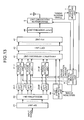
- FIG. 13 is a diagram of a functional configuration example of a transmitting apparatus according to a fourth embodiment.
- FIG. 14 is a diagram of an example of a phase rotator used in a phase rotation unit.
- FIG. 15 is a diagram of an example of a signal arrangement of pilot symbols and DFT output symbols arranged using Formula (2).
- FIG. 16 is a diagram of comparison of a phase rotation for an SC signal and a phase rotation for an MC signal.
- FIG. 17 is a diagram of an example of divided phase rotation for an SC signal.
- FIG. 18 is a diagram of a functional configuration example of a transmitting apparatus according to a fifth embodiment.
- FIG. 19 is a diagram of a functional configuration example of a transmitting apparatus according to a sixth embodiment.
- FIG. 20 is a diagram of a functional configuration example of a transmitting apparatus according to a seventh embodiment.
- FIG. 21 is a diagram of a functional configuration example of a transmitting apparatus according to an eighth embodiment.
- FIG. 22 is a diagram of an example of a control method according to a ninth embodiment.
- FIG. 23 is a diagram of a functional configuration example of a transmitting apparatus according to a tenth embodiment.
- FIG. 24 is a diagram of a configuration example of a transmitting apparatus according to the tenth embodiment when storing an IDFT output signal.
- FIG. 25 is a diagram of a configuration example of the transmitting apparatus according to the tenth embodiment for reducing a computational amount.
- FIG. 26 is a diagram of an example of a method of searching for a cyclic shift amount.
- FIG. 27 is a diagram of an example of a procedure for searching for a cyclic shift amount in a control-signal generating unit.
- FIG. 28 is a diagram of an example of a cyclic shift.
- a transmitting apparatus, a receiving apparatus, a communication system, and a communication method according to embodiments of the present invention are explained below based on the drawings.
- the present invention is not limited by the embodiments.
- FIG. 1 is a diagram of a functional configuration example of the transmitting apparatus according to a first embodiment of the present invention.
- the transmitting apparatus includes a group processing unit 1 , signal processing units 2 - 1 to 2 -M (M is an integer equal to or larger than 2), control processing units 3 - 1 to 3 -M, a combination processing unit 4 , a transmission processing unit 5 , a transmission antenna 6 , a power measuring unit 7 , and a control-signal generating unit 8 .
- a transmission signal is input to the group processing unit 1 as an input signal.
- the input signal is a digital modulation signal modulated by a system such as PSK or QAM.
- the input signal can be a signal affixed with an error correction code.
- the group processing unit 1 divides one block of the input signal into M and inputs divided data respectively to the signal processing units 2 - 1 to 2 -M. Although the group processing unit 1 divides the one block into M, the group processing unit 1 can divide data of the one block into a number smaller than M. When dividing the one block, the group processing unit 1 can divide the one block to equalize data amounts of divided data or can divide the one block to vary a data amount for each of the divided data.
- the one block can be configured by any number of symbols.
- the one block is a data amount transmitted in one transmission in the transmitting apparatus in the past.
- a transmission signal is subjected to DFT processing in a predetermined number of symbol units to perform arrangement on a frequency and, thereafter, the transmission signal is converted into a time domain signal by IDFT processing and transmitted.
- a predetermined number of symbols are set as the one block.
- the signal processing units 2 - 1 to 2 -M respectively carry out predetermined signal processing on the input divided data and respectively input the processed divided data to the control processing units 3 - 1 to 3 -M.
- predetermined signal processing for example, DFT processing or the like is carried out.
- the control processing units 3 - 1 to 3 -M carry out predetermined control processing on the input data based on a control signal from the control-signal generating unit 8 .
- the predetermined control processing is processing for suppressing transmission power.
- the predetermined control processing is, for example, a phase rotation, a timing shift, a cyclic shift, or a power distribution or can be a combination of these kinds of processing.
- the combination processing unit 4 combines the divided data subjected to the predetermined control processing by the control processing units 3 - 1 to 3 -M into one combined signal with predetermined combination processing and inputs the combined signal to the transmission processing unit 5 .
- the predetermined combination processing is, for example, IDFT processing and can include CP insertion processing, ZP processing, and the like.
- the transmission processing unit 5 carries out, on the combined signal combined by the combination processing unit 4 , predetermined transmission processing for transmitting the combined signal as a radio signal, converts the combined signal into a transmission signal, and transmits the transmission signal from the transmission antenna 6 .
- the power measuring unit 7 measures power of the transmission signal output from the transmission processing unit 5 and acquires predetermined power information.
- a request to the transmitting apparatus according to this embodiment is specified (set as a design value or the like) in the predetermined power information.
- transmission peak power, transmission average power, a PAPR (Peak to Average Power ratio), or the like can be used.
- the control-signal generating unit 8 generates, based on the power information acquired by the power measuring unit 7 , a control signal for controlling the control processing units 3 - 1 to 3 -M to set the power information to satisfy a target value and inputs the generated control signal to the control processing units 3 - 1 to 3 -M.
- the target value is, for example, a design target concerning the transmission power.
- the power measuring unit 7 acquires the transmission peak power as power information.
- the control-signal generating unit 8 generates a control signal to set the transmission peak power to be equal to or smaller than a predetermined target value (a design target, etc.).
- a general design target is to minimize the transmission peak power.
- the design target is not limited to this.
- the operation in this embodiment can be applied as well to a system in which several transmission antennas are used.
- the several transmission antennas can transmit the same transmission signal or can transmit different transmission signals.
- the transmitting apparatus only has to include a plurality of the combination processing units 4 and a plurality of transmission processing units.
- the combination processing units 4 only have to generate a combined signal for each of the transmission antennas.
- the power measuring unit 7 acquires power information for each of the transmission processing units.
- the control-signal generating unit 8 generates, for each of the control processing units 3 - 1 to 3 -M connected to the same transmission antenna, a control signal to set the power information to satisfy the design target.
- the power information is transmission peak power and the design target is the transmission peak power equal to or smaller than the predetermined target value.
- the control-signal generating unit 8 retains, in advance, a plurality of sets of control values to be set in the control processing units 3 - 1 to 3 -M. It is assumed that one set of control values includes control values respectively corresponding to the control processing units 3 - 1 to 3 -M.
- the control-signal generating unit 8 retains, as sets of control values, phase rotation amounts of rotations respectively performed by the control processing units 3 - 1 to 3 -M.
- the control processing units 3 - 1 to 3 -M can be set to directly output input signals from the signal processing units 2 - 1 to 2 -M or control values corresponding to any one set among the sets of the control values can be respectively set in the initial state.
- the control-signal generating unit 8 generates control signals corresponding to a certain set among the retained sets of the control values, inputs the control signals respectively to the control processing units 3 - 1 to 3 -M respectively corresponding to the control signals, and acquires power information corresponding to the set of the control values from the power measuring unit 7 . Similarly, the control-signal generating unit 8 acquires transmission peak power corresponding to all the sets and selects a set of the control values for which the transmission peak power is equal to or smaller than the predetermined target value and optimum. A method of selecting the optimum set of the control values depends on what the power information is and what kind of a design target the design target is.
- the control-signal generating unit 8 when the power information is the transmission peak power, for example, a set of the control values for which the transmission peak power is low can be selected as the optimum set of the control values.
- the control-signal generating unit 8 After selecting the optimum set of the control values, the control-signal generating unit 8 generates control signals corresponding to the selected set of the control values and input the control signals respectively to the control processing units 3 - 1 to 3 -M corresponding thereto.
- the control-signal generating unit 8 has a function of the control-signal generating unit that generates a control signal and a function of a candidate selecting unit that selects a candidate of control values.
- FIG. 2 is a diagram of a functional configuration example of the receiving apparatus according to this embodiment.
- the receiving apparatus according to this embodiment includes a reception antenna 11 , a reception processing unit 12 , a combination-releasing and dividing unit (a dividing unit) 13 , a control-signal generating unit 14 , control-processing removing units 15 - 1 to 15 -M, reception-signal processing units 16 - 1 to 16 -M, and a demodulation processing unit 17 .
- a transmission signal transmitted by the transmitting apparatus is received by the reception antenna 11 of the receiving apparatus and input to the reception processing unit 12 .
- the reception processing unit 12 carries out predetermined reception processing on the received signal and inputs the signal to the combination-releasing and dividing unit 13 .
- the combination-releasing and dividing unit 13 carries out processing in an inverse manner compared to the combination processing by the transmitting apparatus, decomposes the received signal, and inputs decomposed signals respectively to the control-processing removing units 15 - 1 to 15 -M.
- the control-signal generating unit 14 retains, for each of the sets of the control values retained by the transmitting apparatus, sets of control values for removing control (hereinafter referred to as removal control values).
- the control-signal generating unit 14 generates control signals corresponding to a certain set among the retained removal control values and inputs the control signals to the control-processing removing units 15 - 1 to 15 -M.
- the control-processing removing units 15 - 1 to 15 -M carry out, based on the input control signals, processing (control processing removal) in an inverse manner compared to the processing carried out by the control processing units 3 - 1 to 3 -M of the transmitting apparatus. For example, when the control processing is phase rotation, at the receiving apparatus, the signals are rotated by phases, absolute values of which are the same as and signs of which are opposite to the phase rotation amounts of the rotation by the transmitting apparatus.
- the reception-signal processing units 16 - 1 to 16 -M carry out, on the signals respectively subjected to the control processing removal by the control-processing removing units 15 - 1 to 15 -M, processing in an inverse manner compared to the processing carried out by the signal processing units 2 - 1 to 2 -M and input the signals to the demodulation processing unit 17 .
- the demodulation processing unit 17 carries out, on the signals input from the signal processing units 2 - 1 to 2 -M, demodulation processing corresponding to the modulation and the encoding processing carried out on the transmission side and inputs demodulation errors (metric values) obtained by the demodulation processing to the control-signal generating unit 14 .
- the control-signal generating unit 14 retains the metrics (the metric values) input from the demodulation processing unit 17 in association with the sets of the removal control values. Thereafter, in the same manner, the control-signal generating unit 14 acquires the metrics corresponding to all the retained sets of the removal control values.
- the control-signal generating unit 14 selects a set of the removal control values with a low metric as an optimum set, generates control signals corresponding to the selected set of the removal control values, and inputs the control signals respectively to the control-processing removing units 15 - 1 to 15 -M. Thereafter, the control processing removal is carried out based on the control signals corresponding to the selected set of the removal control values.
- FIG. 3 is a diagram of a functional configuration example of the transmitting apparatus that transmits the pilot signal.
- the configuration of the transmitting apparatus is the same as the configuration shown in FIG. 1 except that a pilot-symbol generating unit 9 and a control processing unit 3 -(M+1) are added.
- the pilot-symbol generating unit 9 generates predetermined pilot symbols.
- the control processing unit 3 -(M+1) applies predetermined control processing to the pilot symbols.
- the combination processing unit 4 combines the pilot signal with divided data to generate a combined signal.
- the control-signal generating unit 8 retains sets of control values corresponding to the control processing units 3 - 1 to 3 -(M+1) and generates control signals for the control processing units 3 - 1 to 3 -(M+1).
- the other operations are the same as the operations in the example shown in FIG. 1 .
- FIG. 4 is a configuration example of a receiving apparatus that receives a transmission signal transmitted by the transmitting apparatus shown in FIG. 3 .
- the receiving apparatus shown in FIG. 4 is the same as the receiving apparatus shown in FIG. 2 except that a pilot processing unit 18 is added.
- the combination-releasing and dividing unit 13 inputs decomposed pilot symbols to the pilot processing unit 18 .
- the pilot processing unit 18 carries out processing such as transmission line estimation using the pilot symbols and inputs a processing result to the demodulation processing unit 17 .
- the demodulation processing unit 17 performs demodulation processing using this transmission line estimated value.
- the other operations are the same as the operations in the example shown in FIG. 2 .
- the pilot-symbol generating unit 9 generates pilot symbols, which are known signal.
- the combination processing unit 4 combines data and the pilot symbols. Consequently, it is possible to insert the pilot symbols among data of one block.
- the pilot symbols are transmitted for each data of a predetermined number of blocks.
- the data of one block is divided in the same manner as the first embodiment.
- the pilot symbols can be arranged among the divided data. Therefore, a degree of freedom of the arrangement of the pilot symbols is increased.
- the pilot symbols When the pilot symbols are combined with the data and transmitted in this way, peak power is high compared with a transmission of only the data.
- an appropriate set of the control values is selected based on the power information to perform the predetermined control processing. Therefore, the peak power can be suppressed even when the pilot symbols is combined with the data and transmitted.
- any symbols can be used.
- a sequence for suppressing peak power such as a Zadoff Chu sequence introduced in ‘S. Beyme and C. Leung, “Efficient computation of DFT of Zadoff-Chu Sequences”, Electronics Letters, vol. 45, no. 9, Apr. 2009, pp. 461-463’ can be used.
- FIG. 5 is a diagram of an example of a selection procedure for a set of removal control values (a candidate of control values) carried out by the control-signal generating unit 14 in this embodiment.
- the number of all retained sets of removal control values is represented as C and an optimum candidate is selected out of C candidates, i.e., a candidate # 1 to a candidate #C.
- C the number of all retained sets of removal control values
- the control-signal generating unit 14 sets a metric value for comparison x to the infinite (as a large value as possible) (step S 1 ). Subsequently, the control-signal generating unit 14 selects the candidate # 1 out of the C candidates and sets a candidate number k of the selected candidate # 1 to 1 (step S 2 ).
- the control-signal generating unit 14 generates control signals corresponding to the removal control values of the candidate #k, inputs the control signals to the control-processing removing units 15 - 1 to 15 -M, and carries out the demodulation processing (step S 3 ).
- the control-signal generating unit 14 acquires a metric value x k of a demodulation result for the candidate #k from the demodulation processing unit 17 (step S 4 ) and determines whether x k is smaller than x (step S 5 ).
- the control-signal generating unit 14 sets x to be equal to x k and sets best_cand (a number of an optimum candidate) to be equal to k (step S 6 ). Thereafter, the control-signal generating unit 14 sets k to be equal to k+1 and selects the candidate #(k+1) (step S 7 ) and determines whether k is larger than C (step S 8 ). When k is larger than C (Yes at step S 8 ), the control-signal generating unit 14 outputs, as an output result, a demodulation result corresponding to best_cand (step S 9 ).
- step S 5 When x k is equal to or larger than x at step S 5 (No at step S 5 ), the control-signal generating unit 14 proceeds to step S 7 . When k is equal to or smaller than C at step S 8 (No at step S 8 ), the control-signal generating unit 14 returns to step S 3 .
- the above explanation is based on the premise that the receiving apparatus does not know which set of the control values is selected in the transmitting apparatus.
- the transmitting apparatus can notify, by some means, the receiving apparatus which set of the control values is selected.
- the control-signal generating unit 14 of the receiving apparatus does not need to carry out, for all the sets of the removal control values, processing for acquiring a metric and only has to select a set of the removal control values based on the notification.
- data to be transmitted is divided into a plurality of divided data.
- the control processing units 3 - 1 to 3 -M perform the predetermined control processing for each of the divided data.
- the combination processing unit 4 combines signals subjected to the control processing.
- the transmission processing unit 5 transmits a combined signal.
- the power measuring unit 7 acquires power information based on electric power of a transmission signal generated by the transmission processing unit 5 .
- the control-signal generating unit 14 retains a plurality of sets of control values, selects one of the retained sets based on the power information, generates control signals based on the selected control value, and inputs the control signals to the control processing units 3 - 1 to 3 -M. Therefore, it is possible to suppress the transmission power.
- FIG. 6 is a diagram of a functional configuration of the transmitting apparatus according to a second embodiment of the present invention.
- the configuration of the transmitting apparatus according to this embodiment is the same as the example shown in FIG. 3 in the first embodiment except that the transmitting apparatus includes a pilot-symbol generating unit 9 a instead of the pilot-symbol generating unit 9 .
- Components having functions same as the functions in the first embodiment are denoted by reference numerals and signs same as the reference numerals and signs in the first embodiment. Redundant explanation of the components is omitted.
- pilot symbols are set to different values according to a selected set (candidate) of control values. Consequently, on a reception side, it is possible to learn, based on the pilot symbols, a candidate selected on a transmission side. It is possible to reduce processing on the reception side.
- control processing is not applied to an output of the pilot-symbol generating unit 9 a .
- the control processing can be applied to the output of the pilot-symbol generating unit 9 a .
- control processing e.g., power control
- control processing having little influence in specifying a pilot sequence can be applied to the output of the pilot-symbol generating unit 9 a as well.
- FIG. 7 is a diagram of an example of a processing procedure by the control-signal generating unit 8 in this embodiment.
- FIG. 8 is a diagram of a configuration example of the control-signal generating unit 8 and the pilot-symbol generating unit 9 a in this embodiment. An operation example for setting pilot symbols to different values depending on a selected set (candidate) of control values is explained with reference to FIGS. 7 and 8 .
- the control-signal generating unit 8 in this embodiment includes a selecting unit 81 , a selecting circuit 82 , and a memory 83 .
- the C candidates (sets) of control values (the control value candidate # 1 to the control value candidate #C) explained in the first embodiment are stored.
- the pilot-symbol generating unit 9 a in this embodiment includes a selecting circuit 91 and a memory 92 .
- a pilot sequence # 1 to a pilot sequence #C are stored. It is assumed that the pilot sequences # 1 to the pilot sequence #C are sequences different from one another. “Sequence” is complex numbers or real numbers arranged in fixed order. However, the sequence is not limited to this and any sequence can be used.
- the selecting unit 81 sets the peak power for comparison x to the infinite (as large a value as possible) (step S 11 ). Subsequently, the selecting unit 81 selects the control value candidate # 1 out of the C control value candidates stored in the memory 83 and sets the candidate number k of the selected control value candidate # 1 to 1 (step S 12 ).
- the selecting unit 81 generates control signals corresponding to the control value candidate #k, inputs the control signals to the control processing units 3 - 1 to 3 -M, and inputs, to the pilot-symbol generating unit 9 a , a selection signal for notifying that the candidate number (k) is selected.
- the pilot-symbol generating unit 9 a selects, based on the selection signal, a symbol sequence corresponding to the candidate number (k) and inputs the symbol sequence to the combination processing unit 4 as pilot symbols (step S 13 ). Consequently, a combined signal is generated using the control value and the symbol sequence corresponding to the candidate number k and input to the transmission processing unit 5 .
- control-signal generating unit 8 When k is larger than C (Yes at step S 18 ), the control-signal generating unit 8 generates control signals based on a set of the control values corresponding to best_cand, inputs the control signals to the control processing units 3 - 1 to 3 -M, and inputs a selection signal for selecting the candidate number best_cand to the pilot-symbol generating unit 9 (step S 19 ).
- step S 15 When x k is equal to or larger than x at step S 15 (No at step S 15 ), the control-signal generating unit 8 proceeds to step S 17 . When k is equal to or smaller than C at step S 18 (No at step S 18 ), the control-signal generating unit 8 returns to step S 13 .
- FIG. 9 is a diagram of the example in which the cyclic shift is used. It is assumed that the group processing unit 1 divides data of one block into two divided data (two groups), the number of pilot symbols per one sequence is set to 2, and the number of sets (the number of candidates) C of control values is set to 3. Each of the signal processing units 2 - 1 to 2 -M outputs three signals (each of the divided data includes three signals).
- the signal processing unit 2 - 1 outputs signals S 0 , S 1 , and S 2 .
- the signal processing unit 2 - 2 outputs signals T 0 , T 1 , and T 2 .
- the control value candidates # 1 , # 2 , and # 3 are respectively 0 shift, +1 shift, and +2 shift. Pilot sequences corresponding to the 0 shift are represented as P 01 and P 02 , pilot sequences corresponding to the +1 shift are represented as P 11 and P 12 , and pilot sequences corresponding to the +2 shift are represented as P 21 and P 22 .
- the +1 shift no shift and the +1 shift are respectively set for the control processing units 3 - 1 and 3 - 2 as control values.
- the +2 shift no shift and the +1 shift are respectively set for the control processing units 3 - 1 and 3 - 2 as control values.
- the signals are combined in the combination processing unit 4 in the order of the output by the signal processing units 2 - 1 and 2 - 2 .
- the signals output by the signal processing unit 2 - 2 are subjected to the +1 shift by the control processing unit 3 - 2 and output to the combination processing unit 4 .
- the pilot sequences P 11 and P 12 are generated as pilot symbols and input to the combination processing unit 4 .
- FIG. 10 is a diagram of a functional configuration example of the receiving apparatus according to this embodiment.
- the receiving apparatus according to this embodiment is the same as the example shown in FIG. 4 in the first embodiment except that the receiving apparatus includes a control-signal generating unit 14 a and a pilot processing unit 18 a instead of the control-signal generating unit 14 and the pilot processing unit 18 .
- the combination-releasing and dividing unit 13 inputs decomposed pilot symbols to the pilot processing unit 18 a .
- the pilot processing unit 18 a carries out processing such as transmission line estimation using the pilot symbols and inputs a processing result to the demodulation processing unit 17 .
- the pilot processing unit 18 a in this embodiment retains a pilot sequence for each control value candidate retained by the transmitting apparatus.
- the pilot processing unit 18 a compares the retained pilot sequence and a pilot sequence included in the reception signal (e.g., correlation processing) to thereby determine which pilot sequence is transmitted and inputs a result of the determination (a candidate number) to the control-signal generating unit 14 a as a selection signal.
- the control-signal generating unit 14 a selects, based on the selection signal, a set (a candidate) of retained removal control values, generates control signals, and inputs the control signals to the control-processing removing units 15 - 1 to 15 -M.
- the pilot sequences are set to correspond to the candidates of the control values in a one-to-one relation.
- the transmitting apparatus generates a pilot sequence corresponding to a selected candidate of the control values as pilot symbols and transmits the pilot symbols while including the pilot symbols in a combined signal. Therefore, it is possible to obtain an effect same as the effect in the first embodiment and reduce processing by the receiving apparatus.
- FIG. 11 is a diagram of a functional configuration example of the transmitting apparatus according to a third embodiment of the present invention.
- the configuration of the transmitting apparatus according to this embodiment is the same as the configuration of the transmitting apparatus according to the second embodiment except that a parameter calculating unit 10 is added, the power measuring unit 7 is removed, and a control-signal generating unit 8 a is provided instead of the control-signal generating unit 8 .
- Components having functions same as the functions in the second embodiment are denoted by reference numerals and signs same as the reference numerals and sigs in the second embodiment. Redundant explanation of the components is omitted.
- the method of selecting an optimum control signal based on power information of a transmission signal is explained.
- a control value to be selected as an optimum value can be selected beforehand according to an input signal or the like.
- an example in which a control value to be selected as an optimum value is selected beforehand is explained.
- an input signal is input to the group processing unit 1 and input to the parameter calculating unit 10 .
- the parameter calculating unit 10 selects, based on the input signal, an optimum candidate out of C candidates of control values through calculation.
- the parameter calculating unit 10 inputs a selection signal indicating a candidate number of the selected candidate to the control-signal generating unit 8 a and the pilot-symbol generating unit 9 a.
- FIG. 12 is a diagram of a configuration example of the control-signal generating unit 8 a and the pilot-symbol generating unit 9 a in this embodiment.
- the configuration of the pilot-symbol generating unit 9 a is the same as the configuration in the second embodiment.
- the selection signal is input from the parameter calculating unit 10 .
- the control-signal generating unit 8 a has a configuration in which the selecting unit 81 is removed from the control-signal generating unit 8 in the first embodiment.
- the selecting circuit 82 selects a control value candidate based on the selection signal input from the parameter calculating unit 10 . Operations in this embodiment other than the operations explained above are the same as the operations in the second embodiment.
- control-signal generating unit 8 has the function of the candidate selecting unit that selects a candidate.
- parameter calculating unit 10 has a function of a candidate selecting unit that selects a candidate, power information of which satisfies a target (e.g., transmission peak power is the minimum) through calculation.
- the parameter calculating unit 10 is added to a configuration same as the configuration in the second embodiment.
- the parameter calculating unit 10 is added to a transmitting apparatus having a configuration same as the configuration in the first embodiment and the control-signal generating unit 8 a is provided instead of the control-signal generating unit 8 , whereby an optimum candidate can be selected through calculation as in the this embodiment.
- the parameter calculating unit 10 selects an optimum candidate of control values based on the input signal. Therefore, it is possible to obtain a same effect as the effect in the second embodiment and reduce processing by the transmitting apparatus.
- FIG. 13 is a diagram of a functional configuration example of the transmitting apparatus according to a fourth embodiment of the present invention.
- a specific example in which the transmitting apparatus explained in the second embodiment is used as a transmitting apparatus that performs SC transmission is explained. As shown in FIG.
- the transmitting apparatus includes an S/P (serial-parallel conversion) unit 21 , a modulating unit 22 , DFT units (Fourier transform units) 23 - 1 to 23 -M, phase rotation units 31 - 1 to 31 -M, a frequency arranging unit 41 , an IDFT unit (inverse Fourier transform unit) 42 , a P/S unit 43 , a CP/ZP inserting unit 44 , the transmission processing unit 5 , the transmission antenna 6 , the power measuring unit 7 , the control-signal generating unit 8 , and the pilot-symbol generating unit 9 a.
- S/P serial-parallel conversion
- the transmission processing unit 5 , the transmission antenna 6 , the power measuring unit 7 , the control-signal generating unit 8 , and the pilot-symbol generating unit 9 a are respectively the same as the transmission processing unit 5 , the transmission antenna 6 , the power measuring unit 7 , the control-signal generating unit 8 , and the pilot-symbol generating unit 9 a in the second embodiment.
- the DFT units 23 - 1 to 23 -M are equivalent to the signal processing units 2 - 1 to 2 -M in the second embodiment.
- the phase rotation units 31 - 1 to 31 -M are equivalent to the control processing units 3 - 1 to 3 -M in the second embodiment.
- the frequency arranging unit 41 , the IDFT unit 42 , the P/S unit 43 , and the CP/ZP inserting unit 44 are equivalent to the combination processing unit 4 .
- the S/P unit 21 and the modulating unit 22 have the function of the group processing unit 1 in the second embodiment.
- the input signal is explained as being the modulation signal.
- modulation can be performed in the group processing unit 1 .
- the S/P unit 21 converts an input signal, which is a series signal, into a parallel signal and inputs the input signal to the modulating unit 22 .
- the modulating unit 22 digitally modulates the input signal into modulated data, divides the modulated data into G (G is an integer equal to or larger than 2 and equal to or smaller than M) groups, and inputs the divided modulated data respectively to the different DFT units 23 - 1 to 23 -M.
- G is an integer equal to or larger than 2 and equal to or smaller than M
- the DFT units 23 -M respectively apply DFT to the input modulated data to thereby generate SC signals and input the SC signals to the phase rotation units 31 - 1 to 31 -M connected to the DFT units 21 - 1 to 21 -G.
- FFT Fast Fourier Transform
- the phase rotation units 31 - 1 to 31 -M respectively give phase rotations to the input SC signals based on control signals input from the control-signal generating unit 8 .
- a phase rotator shown in FIG. 14 can be used as the phase rotation units 31 - 1 to 31 -M.
- a phase rotation amount can be determined in any way.
- a phase rotation amount indicated by Formula (1) can be used as a phase rotation amount given by an nth phase rotation unit 31 -n.
- ⁇ m is a phase rotation amount instructed to the nth phase rotation unit 31 -n.
- ⁇ (n) m exp( j ⁇ n m/N n ),0 ⁇ m ⁇ N n ⁇ 1 (1)
- s( n ) m indicates an input mth symbol of the nth group and y (n) m indicates an output mth signal (a signal subjected to phase rotation) of the nth group.
- FIG. 15 is a diagram of an example of a signal arrangement of pilot symbols and DFT output symbols arranged using Formula (2).
- SC signals subjected to the phase rotation by the phase rotation units 31 - 1 to 31 -M and the pilot symbols output from the pilot-symbol generating unit 9 a are input to the frequency arranging unit 41 , distributedly arranged on a frequency by the frequency arranging unit 41 , and input to the IDFT unit 42 .
- the IDFT unit 42 carries out IDFT processing on a signal in a frequency domain input from the frequency arranging unit 41 to thereby generate a combined signal in a time domain.
- IFFT Inverse FFT
- the P/S unit 43 converts the combined signal, which is a parallel signal, into a series signal and inputs the combined signal to the CP/ZP inserting unit 44 .
- the CP/ZP inserting unit 44 carries out CP processing, ZP insertion processing, or the like on the input signal and inputs the signal to the transmission processing unit 5 .
- the operations of the transmission processing unit 5 , the transmission antenna 6 , the power measuring unit 7 , and the control-signal generating unit 8 , and the pilot-symbol generating unit 9 a are the same as the operations in the second embodiment.
- Phase rotation amounts of the rotation by the phase rotation units 31 - 1 to 31 -M is instructed by a control signal from the control-signal generating unit 8 .
- the control-signal generating unit 8 retains a plurality of candidates (sets) of control values.
- the candidates can be set in any way. A specific example is explained below.
- phase rotation amounts (control values) for phase rotation are set to three types of 0, ⁇ , and ⁇ .
- a phase rotation amount given to a first group is represented as a
- a phase rotation amount given to a second group is represented as b
- a phase rotation amount given to a third group is represented as c
- the control-signal generating unit 8 selects, based on power information, a candidate with minimum transmission peak power among the nine candidates, generates control signals corresponding to the selected candidate, and inputs the control signals to the phase rotation units 31 - 1 to 31 -G.
- the control-signal generating unit 8 inputs a candidate number corresponding to the selected candidate to the pilot-symbol generating unit 9 a as a selection signal.
- phase rotation amounts for the symbols are determined as indicated by Formula (1).
- the number of candidates of the phase rotation amounts is an extremely large number.
- FIG. 16 is a diagram of comparison of a phase rotation for an SC signal (phase rotation in performing the SC transmission) and phase rotation for an MC signal (phase rotation in performing the MC transmission).
- the phase rotation for an SC signal in not performing division of data is shown in the upper part and the phase rotation for an MC signal is shown in the lower part.
- FIG. 17 is a diagram of an example of divided phase rotation for an SC signal.
- an example of phase rotation for an SC signal in dividing modulated data into a plurality of groups and performing DFT as explained in this embodiment is shown.
- a phase rotation amount in instructing a kth candidate among C candidates to an nth group (to the phase rotation unit 31 -n) is represented as ⁇ (k,n)
- a phase rotation amount for an mth symbol of the nth group can be represented by the following Formula (3).
- ⁇ (n) m exp( j ⁇ (k,n) m/N ), 0 ⁇ m ⁇ N ⁇ 1, 0 ⁇ n ⁇ M ⁇ 1 (3)
- a receiving apparatus is the same as the receiving apparatus explained in the second embodiment.
- the control-processing removing unit and the reception-signal processing unit explained in this embodiment only have to carry out processing in an inverse manner compared to the processing on the transmitting apparatus side.
- FIG. 18 is a diagram of a functional configuration example of the transmitting apparatus according to a fifth embodiment of the present invention.
- the transmitting apparatus includes S/P units 21 - 1 to 21 -L (L is an integer equal to or larger than C), modulating units 22 - 1 to 22 -L, DFT units 23 - 1 to 23 -(L ⁇ M), phase rotation units 31 - 1 to 31 -(L ⁇ M), frequency arranging units 41 - 1 to 41 -L, IDFT units 42 - 1 to 42 -L, power measuring units 7 - 1 to 7 -L, a transmission-signal selecting unit 100 , the transmission processing unit 5 , the transmission antenna 6 , and the pilot-symbol generating units 9 - 1 to 9 -L.
- the transmission processing unit 5 and the transmission antenna 6 are the same as the transmission processing unit 5 and the transmission antenna 6 in the first embodiment.
- the S/P units 21 -i, the modulating units 22 -i, the DFT units 23 -(M ⁇ (i ⁇ 1)+1) to 23 -(i ⁇ M), the phase rotation units 31 -(i ⁇ (M ⁇ 1)+1) to 31 -(i ⁇ M), the frequency arranging units 41 -i, the IDFT units 42 -i, and the power measuring units 7 -i are respectively the same as the S/P unit 21 , the modulating unit 22 , the DFT units 23 - 1 to 23 -M, the phase rotation units 31 - 1 to 31 -M, the frequency arranging unit 41 , the IDFT unit 42 , and the power measuring unit 7 , respectively in the fourth embodiment.
- the transmitting apparatus includes L sets of the transmission-signal generating units each including the S/P unit 21 , the modulating unit 22 , the DFT units 23 - 1 to 23 -M, the phase rotation units 31 - 1 to 31 -M, the frequency arranging unit 41 , the IDFT unit 42 , and the power measuring unit 7 in the fourth embodiment.
- a P/S unit and a CP/ZP inserting unit are not shown.
- the transmitting apparatus includes the P/S unit and the CP/ZP inserting unit for each of the transmission-signal generating units as in the fourth embodiment.
- the transmitting apparatus instead of the control-signal generating unit 8 sequentially setting candidates of phase rotation amounts, the transmitting apparatus includes the transmission-signal generating units equal to or more than the number of phase rotation amounts C.
- Phase rotation amounts corresponding to the candidates are set in advance in the phase rotation units 31 - 1 to 3 1 -(L ⁇ M) of the transmission-signal generating units, whereby power information for each of the candidates is obtained at a time.
- phase rotation amounts are fixed and set in advance, for example, candidates of a first phase rotation amount are set in the phase rotation units 31 - 1 to 31 -M and candidates of a second phase rotation amount are set in the phase rotation units 31 -M+1) to 31 - 2 M.
- a pilot symbol generating unit 9 -k generates a symbol sequence corresponding to a candidate number of a kth phase rotation amount.
- the transmission-signal selecting unit 100 selects power information with minimum transmission peak power among L kinds of power information input from the power measuring units 7 - 1 to 7 -L, selects, as a combined signal subjected to optimum control processing, a combined signal input from the transmission-signal generating unit corresponding to the selected power information, and outputs the combined signal to the transmission processing unit 5 .
- the transmitting apparatus includes the transmission-signal generating units equal to or more than the number of phase rotation amounts C.
- Phase rotation amounts corresponding to the candidates are set in advance in the phase rotation units 31 - 1 to 31 -(L ⁇ M) of the transmission-signal generating units, whereby power information for each of candidates is obtained at a time.
- the transmission-signal selecting unit 100 selects an optimum combined signal based on power information. Therefore, it is possible to obtain a same effect as the effect in the fourth embodiment and select a transmission signal subjected to optimum control processing in a short time.
- FIG. 19 is a diagram of a functional configuration example of the transmitting apparatus according to a sixth embodiment of the present invention.
- the transmitting apparatus according to this embodiment is the same as the transmitting apparatus according to the fourth embodiment except that power control units 32 - 1 to 32 -(M+1) are added to the transmitting apparatus according to the fourth embodiment.
- Components having functions same as the functions in the forth embodiment are denoted by reference numerals and signs same as the reference numerals and signs in the fourth embodiment. Redundant explanation of the components is omitted.
- phase rotation is performed as the control processing.
- both of phase rotation and power control are performed. Signals subjected to the phase rotation by the phase rotation units 31 - 1 to 31 -M and pilot symbols generated by the pilot-symbol generating unit 9 a are respectively input to the power control units 32 - 1 to 32 -(M+1).
- the power-control units 32 - 1 to 32 -(M+1) control, based on a control signal input from the control-signal generating unit 8 , electric power (the magnitude of signals) to set a predetermined power distribution to a predetermine distribution ratio.
- M is set to 2
- four types of “1:1:1”, “1:2:1”, “2:1:2”, and “1:1:2” are prepared as candidates of three distribution ratios of the power control units 32 - 1 to 32 - 3 , and control signals are generated in order based on the candidates.
- the control-signal generating unit 8 can sequentially set candidates of phase rotation amounts and acquire power information concerning all the combinations and select an optimum combination. Alternatively, the control-signal generating unit 8 can select one of the phase rotation and the power control according to an input signal and other conditions and select an optimum candidate from C1 or C2 combinations.
- control processing i.e., the phase rotation and the power control
- other two or more kinds of control processing such as a cyclic shift and power control can be combined or three or more kinds of control processing can be combined.
- both of the phase rotation and the power control are performed as the control processing. Therefore, it is possible to more effectively suppress transmission peak power compared with transmission peak suppression performed by using one control processing.
- FIG. 20 is a diagram of a functional configuration example of the transmitting apparatus according to a seventh embodiment of the present invention.
- the transmitting apparatus according to this embodiment is the same as the transmitting apparatus according to the fourth embodiment except that the power measuring unit 7 is removed, the parameter calculating unit 10 is added, and the control-signal generating unit 8 a is provided instead of the control-signal generating unit 8 .
- Components having functions same as the functions in the fourth embodiment are denoted by reference numerals and signs same as the reference numerals and signs in the fourth embodiment. Redundant explanation of the components is omitted.
- an optimum candidate is selected by parameter calculation as in the third embodiment.
- the parameter calculating unit 10 in this embodiment is the same as the parameter calculating unit 10 explained in the third embodiment.
- the parameter calculating unit 10 selects, based on an input signal, an optimum candidate of control values (phase rotation amounts in this case) and inputs a selection signal to the control-signal generating unit 8 a and the pilot-symbol generating unit 9 a .
- the control-signal generating unit 8 a generates, based on the selection signal, control signals corresponding to the optimum candidate and inputs the control signals to the phase rotation units 31 - 1 to 31 -M.
- Operations in this embodiment other than the operations explained above are the same as the operations in the third or fourth embodiment.
- FIG. 21 is a diagram of a functional configuration example of the transmitting apparatus according to an eighth embodiment of the present invention.
- the transmitting apparatus according to this embodiment is the same as the transmitting apparatus according to the sixth embodiment except that the power measuring unit 7 is removed, the parameter calculating unit 10 is added, and the control-signal generating unit 8 a is provided instead of the control-signal generating unit 8 .
- Components having functions same as the functions in the sixth embodiment are denoted by reference numerals and signs same as the reference numerals and signs in the sixth embodiment. Redundant explanation of the components is omitted.
- an optimum candidate is selected by parameter calculation as in the third embodiment.
- the parameter calculating unit 10 in this embodiment is the same as the parameter calculating unit 10 explained in the third embodiment.
- the parameter calculating unit 10 selects, based on an input signal, an optimum candidate of control values (phase rotation amounts and distribution ratios of power distribution in this case) and inputs a selection signal to the control-signal generating unit 8 a and the pilot-symbol generating unit 9 a.
- control-signal generating unit 8 a generates, based on the selection signal, control signals corresponding to the optimum candidate and inputs the control signals to the phase rotation units 31 - 1 to 31 -M and the power control units 32 - 1 to 32 -(M+1). Operations in this embodiment other than the operations explained above are the same as the operations in the third or sixth embodiment.
- the method of dividing data of one block and selecting a control method to set transmission power of a symbol of one block to be equal to or smaller than a target value is explained.
- the number of target blocks is represented as NB and the number of candidates of a control method for a signal of one block is represented as C
- the number of candidates of control values is represented as C NB .
- a transmission side stores NB data blocks in a memory and selects an optimum candidate for each of the blocks out of the C NB candidate to minimize transmission peak power of the blocks.
- the transmission side After generating control signals corresponding to a first block based on the selected candidate, the transmission side generates control signals corresponding to the next block. In this way, the transmission side generates control signals for each input of data of one block to generate control signals for the NB blocks.
- a reception side stores controlled NB reception blocks in a memory and performs release and demodulation of control processing.
- FIG. 22 is a diagram of an example of a control method in the ninth embodiment.
- pilot symbols are changed according to a selected candidate.
- a cyclic shift for a first block is represented as a (a shift amount)
- a cyclic shift for a second block is represented as b (a shift amount)
- a shift candidate for two groups is represented as ⁇ a, b ⁇ .
- a transceiver in this embodiment prepares pilot sequences for respective shift candidates and creates a table for reference.
- a pilot sequence of the first block for the shift amount candidate ⁇ +1, +2 ⁇ is ⁇ P51, P52 ⁇ and a pilot sequence of the second block is ⁇ P41, P42 ⁇ .
- the two blocks are used and the control method is the cyclic shift.
- another control method such as phase rotation or apply the control method to a plurality of data blocks.
- a way of arranging pilot symbols in the table for reference can be set using any reference.
- FIG. 23 is a diagram of a functional configuration example of the transmitting apparatus according to a tenth embodiment of the present invention.
- the method of performing the phase rotation to suppress peak power is explained.
- a method of applying peak power suppression control in a time domain is explained.
- a configuration example in which a cyclic shift is applied to signals to multiplex the signals in the time domain is explained.
- the transmitting apparatus includes DFT units 24 - 1 to 24 -M and zero inserting units 25 - 1 to 25 -M.
- the transmitting apparatus arranges, using frequency arranging units 26 - 1 to 26 -M, DFT outputs (outputs from the DFT units 24 - 1 to 24 -M) and zero (zero output from the zero inserting units 25 - 1 to 25 -M) in a frequency domain.
- IDFT units 27 - 1 to 27 -M convert signals arranged in the frequency domain by the frequency arranging units 26 - 1 to 26 -M into time domain signals and output the time domain signals to control processing units 33 - 1 to 33 -M.
- the control processing units 33 - 1 to 33 -M apply predetermined control processing to time domain signals input based on a control processing amount instructed from a control-signal generating unit 8 b .
- the predetermined control processing is processing for suppressing transmission power.
- the predetermined control processing can be phase rotation, a timing shift, a cyclic shift, power distribution, or the like or can be a combination of the phase rotation, the timing shift, the cyclic shift, the power distribution, and the like.
- a multiplexing unit 42 a performs multiplexing of signals subjected to the control processing by the control processing units 33 - 1 to 33 -M and signals output from a pilot-symbol generating unit 9 b .
- any multiplexing method can be used. For example, there is a multiplexing system for adding signals for M channels, where M is a complex number.
- Pilot symbols output from the pilot-symbol generating unit 9 b are time domain signals.
- a signal multiplexed by the multiplexing unit 42 a is transmitted from the antenna 6 through the P/S unit 43 , the CP/ZP inserting unit 44 , and the transmission processing unit 5 .
- the power measuring unit 7 measures transmission peak power of the transmission signal.
- the control-signal generating unit 8 b retains C control processing candidates.
- the control-signal generating unit 8 b selects one of the C control processing candidates and inputs the control processing candidate as a control processing amount.
- the control-signal generating unit 8 b sequentially inputs the control processing amounts until transmission signals corresponding to the C control processing candidates are respectively generated. Consequently, the control-signal generating unit 8 b selects a control processing candidate in which minimum transmission peak power is obtained.
- FIG. 24 is a diagram of a configuration example of the transmitting apparatus according to this embodiment that stores signals output from the IDFT units 27 - 1 to 27 -M.
- the transmitting apparatus includes a storing unit 28 configured to store signals output from the IDFT units 27 - 1 to 27 -M. Consequently, even when the number of control processing candidates C is a large number, it is possible to attain peak power suppression with a small computational amount.
- FIG. 25 is a diagram of a configuration example of the transmitting apparatus according to this embodiment for reducing a computational amount.
- signals output from the IDFT units 27 - 1 to 27 -M can be input to a control-signal generating unit 8 c to select a cyclic shift with which peak power is reduced.
- a method of searching for a cyclic shift amount with which peak power is reduced is not limited.
- An example of the cyclic shift amount is explained.
- the control processing units 33 - 1 to 33 -M perform the cyclic shift processing, the control processing units 33 - 1 to 33 -M are described as cyclic shift units 33 - 1 to 33 -M.
- FIG. 26 is a diagram of an example of the method of searching for a cyclic shift amount.
- M is set to 2
- a dotted line indicates an example of a waveform of an output signal of the IDFT unit 27 - 1 (represented as a channel # 1 )
- a solid line indicates an example of a waveform of an output signal of the IDFT unit 27 - 2 (represented as a channel # 2 ).
- the output signals of the channel # 1 and the channel # 2 are real numbers. However, this method can be used for complex number signals as well.
- a cyclic shift is applied to the signal of the solid line to suppress peak power of a multiplexed signal.
- the number of searched candidates of the cyclic shift are C ⁇ (0, +1, +15, +18, +20) including a case in which the cyclic shift is not applied.
- Such a search is performed by the control-signal generating unit 8 c.
- FIG. 27 is a diagram of an example of a search procedure for a cyclic shift amount in the control-signal generating unit 8 c .
- the control-signal generating unit 8 c sets the peak power value for comparison x to the finite (a large value) (step S 21 ).
- the control-signal generating unit 8 c extracts, based on output signals from the IDFT units 27 - 1 and 27 - 2 , candidates in which peak power is likely to fall among all cyclic shift candidates and updates the number of candidates C (step S 22 ).
- the control-signal generating unit 8 c inputs control processing signals corresponding to the candidate k to the control processing units 33 - 1 to 33 -M and generates a transmission signal formed by a result of control processing corresponding to the candidate k and a pilot signal (step S 24 ).
- the control-signal generating unit 8 c acquires a measured value x k of peak power by the power measuring unit 7 (step S 25 ) and determines whether x k is smaller than x (step S 26 ). When x k is smaller than x (Yes at step S 26 ), the control-signal generating unit 8 c sets x to be equal to x k and set best_cand (a number of an optimum candidate) to be equal to k (step S 27 ).
- the control-signal generating unit 8 c sets k to be equal to k+1 (step S 28 ) and determines whether k is larger than C (step S 29 ). When k is larger than C (Yes at step S 29 ), the control-signal generating unit 8 c inputs control processing signals corresponding to best_cand to the control processing units 33 - 1 to 33 -M and generates a transmission signal formed by a result of control processing corresponding to best_cand and a pilot signal (step S 30 ).
- step S 26 when x k is equal to or larger than x at step S 26 (No at step S 26 ), the control-signal generating unit 8 c proceeds to step S 28 .
- step S 29 When k is equal to or smaller than C at step S 29 (No at step S 29 ), the control-signal generating unit 8 c returns to step S 24 .
- the procedure explained above it is possible to perform peak power suppression with a small number of candidates.
- the example in which the pilot symbols are transmitted is explained above. However, when the pilot signals are not transmitted, processing concerning the pilot symbols only has to be omitted.
- a way of applying the cyclic shift For example, as shown in FIG. 28 , processing for inverting an entire signal every time the cyclic shift is shifted in a one symbol unit in a time domain can be performed. In FIG. 28 , an example in which the cyclic shift is shifted to the right in a one symbol unit and an example in which the cyclic shift is shifted in a two symbol unit are shown.
- the way of applying the cyclic shift is not limited to the cyclic shift at symbol interval.
- the present invention is not limited to this example and can be applied to transmitting apparatuses and receiving apparatuses of various systems including a wired system.
- the content of the control processing the phase rotation, the power control, and the cyclic shift are explained.
- the present invention is not limited to these kinds of control processing.
- Other methods can be used.
- a plurality of methods can be combined.
- the configurations of the transmitting apparatus and the receiving apparatus are not limited to the apparatus configurations explained in the embodiments.
- the frequency arranging unit explained in the embodiments can perform signal arrangement on a frequency in any way.
Landscapes
- Engineering & Computer Science (AREA)
- Computer Networks & Wireless Communication (AREA)
- Signal Processing (AREA)
- Physics & Mathematics (AREA)
- Discrete Mathematics (AREA)
- General Physics & Mathematics (AREA)
- Mathematical Physics (AREA)
- Mobile Radio Communication Systems (AREA)
- Transmitters (AREA)
- Digital Transmission Methods That Use Modulated Carrier Waves (AREA)
Applications Claiming Priority (3)
| Application Number | Priority Date | Filing Date | Title |
|---|---|---|---|
| JP2011138432 | 2011-06-22 | ||
| JP2011-138432 | 2011-06-22 | ||
| PCT/JP2012/054468 WO2012176495A1 (fr) | 2011-06-22 | 2012-02-23 | Appareil de transmission, appareil de réception, système de communication et procédé de communication |
Publications (2)
| Publication Number | Publication Date |
|---|---|
| US20140016452A1 US20140016452A1 (en) | 2014-01-16 |
| US9319168B2 true US9319168B2 (en) | 2016-04-19 |
Family
ID=47422346
Family Applications (1)
| Application Number | Title | Priority Date | Filing Date |
|---|---|---|---|
| US14/006,995 Active 2032-07-02 US9319168B2 (en) | 2011-06-22 | 2012-02-23 | Transmitting apparatus, receiving apparatus, communication system, and communication method |
Country Status (5)
| Country | Link |
|---|---|
| US (1) | US9319168B2 (fr) |
| EP (1) | EP2725717B1 (fr) |
| JP (1) | JP5484637B2 (fr) |
| CA (1) | CA2838038C (fr) |
| WO (1) | WO2012176495A1 (fr) |
Families Citing this family (9)
| Publication number | Priority date | Publication date | Assignee | Title |
|---|---|---|---|---|
| KR102090745B1 (ko) * | 2013-05-23 | 2020-04-14 | 삼성전자주식회사 | 전자장치에서 외부 디스플레이 장치를 이용하여 멀티태스킹을 수행하는 방법 및 장치 |
| JP6363943B2 (ja) * | 2014-12-09 | 2018-07-25 | 日本電信電話株式会社 | 受信装置、通信システム、受信方法、および通信方法 |
| JP6302092B2 (ja) * | 2014-12-18 | 2018-03-28 | 株式会社東芝 | 無線通信装置、集積回路、送信方法、受信方法及び通信方法 |
| CN107710651B (zh) | 2015-08-03 | 2019-06-25 | 三菱电机株式会社 | 发送装置 |
| JP6426637B2 (ja) * | 2016-02-10 | 2018-11-21 | 日本電信電話株式会社 | 通信システムおよび通信方法 |
| JP6378227B2 (ja) * | 2016-03-10 | 2018-08-22 | Necプラットフォームズ株式会社 | ポイントツーポイント無線装置および通信制御方法 |
| CN107846378B (zh) * | 2016-09-19 | 2020-12-15 | 华为技术有限公司 | 一种调制方法、解调方法、相关设备和系统 |
| JP6971569B2 (ja) * | 2016-12-22 | 2021-11-24 | 株式会社東芝 | 送信装置、および送信方法 |
| US11329859B2 (en) * | 2018-02-27 | 2022-05-10 | Mitsubishi Electric Corporation | Wireless transmitter, wireless receiver, wireless communication system, control circuit, and storage medium |
Citations (12)
| Publication number | Priority date | Publication date | Assignee | Title |
|---|---|---|---|---|
| US20040058701A1 (en) * | 2002-06-30 | 2004-03-25 | Samsung Electronics Co., Ltd. | Transmitting/receiving apparatus and method for reducing PAPR in an OFDM mobile communication system |
| JP2004129249A (ja) | 2002-09-12 | 2004-04-22 | Matsushita Electric Ind Co Ltd | 無線送信装置、無線受信装置、および送信キャンセルサブキャリアの選択方法 |
| US20050208906A1 (en) | 2002-09-12 | 2005-09-22 | Matsushita Electric Industrial Co., Ltd | Radio transmission device, radio reception device, and method for selecting transmission cancellation subcarriers |
| JP2005322998A (ja) | 2004-05-06 | 2005-11-17 | Ntt Docomo Inc | 無線通信システム、無線送信機及び無線受信機 |
| US20050265226A1 (en) * | 2004-05-25 | 2005-12-01 | Ntt Docomo, Inc. | Transmission apparatus and receiving apparatus |
| WO2006013693A1 (fr) | 2004-08-05 | 2006-02-09 | Matsushita Electric Industrial Co., Ltd. | Dispositif de transmission radio, dispositif de reception radio, procede de transmission radio, procede de reception radio |
| WO2007007673A1 (fr) | 2005-07-08 | 2007-01-18 | Nec Corporation | Appareil et procédé de génération de signaux |
| JP2009055395A (ja) | 2007-08-28 | 2009-03-12 | Softbank Mobile Corp | 通信装置におけるピーク電力低減装置 |
| CN101741795A (zh) | 2008-11-17 | 2010-06-16 | 中兴通讯股份有限公司 | 多频点多址接入方法和装置 |
| US20100195597A1 (en) * | 2007-09-21 | 2010-08-05 | Toshizo Nogami | Transmission apparatus, reception apparatus, communication system and transmission method |
| JP2010192977A (ja) | 2009-02-16 | 2010-09-02 | Nagoya Institute Of Technology | Fftを用いたsc−fde用フェージング推定・等化方法 |
| US20110188585A1 (en) * | 2008-08-11 | 2011-08-04 | Ntt Docomo, Inc. | Mobile communication system, transmission apparatus, receiving apparatus and method |
Family Cites Families (1)
| Publication number | Priority date | Publication date | Assignee | Title |
|---|---|---|---|---|
| US8699609B2 (en) * | 2008-11-27 | 2014-04-15 | Optis Cellular Technology, Llc | Methods and arrangements for peak to average power ratio reduction |
-
2012
- 2012-02-23 JP JP2013521484A patent/JP5484637B2/ja active Active
- 2012-02-23 CA CA2838038A patent/CA2838038C/fr active Active
- 2012-02-23 US US14/006,995 patent/US9319168B2/en active Active
- 2012-02-23 WO PCT/JP2012/054468 patent/WO2012176495A1/fr active Application Filing
- 2012-02-23 EP EP12802056.7A patent/EP2725717B1/fr active Active
Patent Citations (19)
| Publication number | Priority date | Publication date | Assignee | Title |
|---|---|---|---|---|
| US20040058701A1 (en) * | 2002-06-30 | 2004-03-25 | Samsung Electronics Co., Ltd. | Transmitting/receiving apparatus and method for reducing PAPR in an OFDM mobile communication system |
| JP2004129249A (ja) | 2002-09-12 | 2004-04-22 | Matsushita Electric Ind Co Ltd | 無線送信装置、無線受信装置、および送信キャンセルサブキャリアの選択方法 |
| US20050208906A1 (en) | 2002-09-12 | 2005-09-22 | Matsushita Electric Industrial Co., Ltd | Radio transmission device, radio reception device, and method for selecting transmission cancellation subcarriers |
| JP2005322998A (ja) | 2004-05-06 | 2005-11-17 | Ntt Docomo Inc | 無線通信システム、無線送信機及び無線受信機 |
| US20050259565A1 (en) * | 2004-05-06 | 2005-11-24 | Ntt Docomo, Inc. | Radio communication system, radio transmitter and radio receiver |
| US20050265226A1 (en) * | 2004-05-25 | 2005-12-01 | Ntt Docomo, Inc. | Transmission apparatus and receiving apparatus |
| JP2005341056A (ja) | 2004-05-25 | 2005-12-08 | Ntt Docomo Inc | 送信装置及び受信装置 |
| US7760811B2 (en) * | 2004-08-05 | 2010-07-20 | Panasonic Corporation | Radio transmission device, radio reception device, radio transmission method, and radio reception method |
| WO2006013693A1 (fr) | 2004-08-05 | 2006-02-09 | Matsushita Electric Industrial Co., Ltd. | Dispositif de transmission radio, dispositif de reception radio, procede de transmission radio, procede de reception radio |
| US20070217528A1 (en) | 2004-08-05 | 2007-09-20 | Matsushita Electric Industrial Co.,Ltd | Data transmission device, radio reception device, radio transmission method, and radio reception method |
| US20100297969A1 (en) | 2004-08-05 | 2010-11-25 | Panasonic Corporation | Radio transmission device, radio reception device, radio transmission method, and radio reception method |
| WO2007007673A1 (fr) | 2005-07-08 | 2007-01-18 | Nec Corporation | Appareil et procédé de génération de signaux |
| US20090080454A1 (en) | 2005-07-08 | 2009-03-26 | Nec Corporation | Signal Generating Apparatus and Signal Generation Method |
| JP2009055395A (ja) | 2007-08-28 | 2009-03-12 | Softbank Mobile Corp | 通信装置におけるピーク電力低減装置 |
| US20100195597A1 (en) * | 2007-09-21 | 2010-08-05 | Toshizo Nogami | Transmission apparatus, reception apparatus, communication system and transmission method |
| US20110188585A1 (en) * | 2008-08-11 | 2011-08-04 | Ntt Docomo, Inc. | Mobile communication system, transmission apparatus, receiving apparatus and method |
| CN101741795A (zh) | 2008-11-17 | 2010-06-16 | 中兴通讯股份有限公司 | 多频点多址接入方法和装置 |
| US20120183087A1 (en) | 2008-11-17 | 2012-07-19 | Zte Corporation | Method and apparatus for multiple frequency point multiple access |
| JP2010192977A (ja) | 2009-02-16 | 2010-09-02 | Nagoya Institute Of Technology | Fftを用いたsc−fde用フェージング推定・等化方法 |
Non-Patent Citations (9)
| Title |
|---|
| "Optimum family of spectrum-shaping functions for PAPR reduction in SC-FDMA" Huawei, 3rd Generation Partnership Project (3GPP), Mobile Competence Centre, vol. RAN WG1, XP050101025, Nov. 7-11, 2005, 7 Pages. |
| Benvenuto, N., et al., "Single Carrier Modulation with Nonlinear Frequency Domain Equalization: An Idea Whose Time Has Come-Again", Proceedings of the IEEE, vol. 98, No. 1, pp. 69-96, (Jan. 2010). |
| Beyme, S., et al., "Efficient computation of DFT of Zadoff-Chu sequences", Electronics Letters, vol. 45, No. 9, Total 2 Pages., (Apr. 23, 2009). |
| Bingham, J. A. C., "Multicarrier Modulation for Data Transmission: An Idea Whose Time Has Come", IEEE Communications Magazine, vol. 28, No. 5, pp. 5-14, (May 1990). |
| Extended European Search Report issued May 13, 2015 in Patent Application No. 12802056.7. |
| Fumihiro Hasegawa, Akihiro Okazaki, and Hiroshi Kubo; Peak power reduction techniques for multi-channel SC-OFDM; 2011; IEEE 22nd International Symposium on Personal, Indoor and Mobile Radio Communications; 5 Pages. * |
| Fumihiro Hasegawa, et al., "Peak power reduction techniques for multi-channel SC-OFDM" Personal Indoor and Mobile Radio Communications (PIMRC), 2011 IEEE 22nd International Symposium on Personal, Indoor, and Mobile Radio Communications, XP032102206, Sep. 11, 2011, pp. 1743-1747. |
| International Search Report Issued May 29, 2012 in PCT/JP12/54468, Filed Feb. 23, 2012. |
| Single Carrier Modulation with Nonlinear Frequency Domain Equalization: An Idea whose Time has come-Again, Benvenuto et al. vol. 98, No. 1, Jan. 2010. * |
Also Published As
| Publication number | Publication date |
|---|---|
| EP2725717A4 (fr) | 2015-06-10 |
| EP2725717B1 (fr) | 2018-12-26 |
| CA2838038A1 (fr) | 2012-12-27 |
| US20140016452A1 (en) | 2014-01-16 |
| JP5484637B2 (ja) | 2014-05-07 |
| WO2012176495A1 (fr) | 2012-12-27 |
| EP2725717A1 (fr) | 2014-04-30 |
| JPWO2012176495A1 (ja) | 2015-02-23 |
| CA2838038C (fr) | 2016-09-13 |
Similar Documents
| Publication | Publication Date | Title |
|---|---|---|
| US9319168B2 (en) | Transmitting apparatus, receiving apparatus, communication system, and communication method | |
| US9065630B1 (en) | Systems and methods for detecting secondary synchronization signals in a wireless communication system | |
| US20080192621A1 (en) | Data Communication System and Data Transmitting Apparatus | |
| US10263748B2 (en) | Method and apparatus for transmitting uplink data and user equipment | |
| KR20090019867A (ko) | 가변대역에서 통신하기 위한 장치 및 방법 | |
| EP3531645A1 (fr) | Procédé de configuration de signal de référence, procédé de configuration de champ d'apprentissage, et appareil | |
| JP5486734B2 (ja) | シングルキャリア通信システムにおける送信信号生成装置および方法 | |
| CN104580057B (zh) | 一种单载波mimo系统的时域导频及其同步方法 | |
| KR20100020891A (ko) | 광대역 무선통신 시스템에서 고속 피드백 채널을 이용한 정보 송수신 장치 및 방법 | |
| KR20210129187A (ko) | 채널 및 위상 잡음의 공동 추정을 위한 순회 파일럿 시퀀스 | |
| KR101778304B1 (ko) | 프리앰블을 이용하여 특성 정보를 공유하는 통신 방법, 상기 프리앰블을 생성하는 방법, 상기 방법들이 적용되는 통신 시스템 | |
| US10277448B1 (en) | Method for hierarchical modulation with vector processing | |
| JP2017092555A (ja) | シングルキャリアmimo送信装置及びシングルキャリアmimo受信装置 | |
| US20100166091A1 (en) | Multicarrier transmitter and multicarrier reveiver | |
| CN108449302B (zh) | 一种恒包络的帧同步信号的发射方法和接收方法 | |
| CN104205694A (zh) | 信道估计方法和接收机 | |
| JP4290657B2 (ja) | 空間分割多重信号検出回路および空間分割多重信号検出方法 | |
| CN107872868B (zh) | 信号处理的方法、设备和系统 | |
| KR101226117B1 (ko) | 무선 통신 시스템들에서 타이밍 정보의 획득 | |
| CN110099018B (zh) | Mc-oqam系统中的载波相位恢复方法及装置 | |
| JP2009033666A (ja) | 無線通信装置、無線送信方法及び無線受信方法 | |
| Maruyama et al. | Control information transmission without resource consumption for PAPR reduction of OFDM signal | |
| US11240086B2 (en) | Method, device and storage medium for transferring, by emitter, flow of samples to receiver by emitter | |
| JP2017034500A (ja) | 無線通信システム | |
| CN106797628B (zh) | 双流发射方法和发射机 |
Legal Events
| Date | Code | Title | Description |
|---|---|---|---|
| AS | Assignment |
Owner name: MITSUBISHI ELECTRIC CORPORATION, JAPAN Free format text: ASSIGNMENT OF ASSIGNORS INTEREST;ASSIGNOR:HASEGAWA, FUMIHIRO;REEL/FRAME:031264/0253 Effective date: 20130523 |
|
| STCF | Information on status: patent grant |
Free format text: PATENTED CASE |
|
| MAFP | Maintenance fee payment |
Free format text: PAYMENT OF MAINTENANCE FEE, 4TH YEAR, LARGE ENTITY (ORIGINAL EVENT CODE: M1551); ENTITY STATUS OF PATENT OWNER: LARGE ENTITY Year of fee payment: 4 |
|
| MAFP | Maintenance fee payment |
Free format text: PAYMENT OF MAINTENANCE FEE, 8TH YEAR, LARGE ENTITY (ORIGINAL EVENT CODE: M1552); ENTITY STATUS OF PATENT OWNER: LARGE ENTITY Year of fee payment: 8 |