US9222435B2 - Stirling engine with humidity control - Google Patents
Stirling engine with humidity control Download PDFInfo
- Publication number
- US9222435B2 US9222435B2 US13/579,652 US201113579652A US9222435B2 US 9222435 B2 US9222435 B2 US 9222435B2 US 201113579652 A US201113579652 A US 201113579652A US 9222435 B2 US9222435 B2 US 9222435B2
- Authority
- US
- United States
- Prior art keywords
- stirling engine
- cooler
- humidity
- working fluid
- crankcase
- Prior art date
- Legal status (The legal status is an assumption and is not a legal conclusion. Google has not performed a legal analysis and makes no representation as to the accuracy of the status listed.)
- Expired - Fee Related
Links
- 239000012530 fluid Substances 0.000 claims abstract description 65
- 238000005461 lubrication Methods 0.000 claims abstract description 24
- 238000001816 cooling Methods 0.000 claims description 66
- 239000002826 coolant Substances 0.000 claims description 34
- 239000007858 starting material Substances 0.000 claims description 8
- 238000005192 partition Methods 0.000 claims description 6
- 238000002485 combustion reaction Methods 0.000 description 18
- 238000009833 condensation Methods 0.000 description 17
- 230000005494 condensation Effects 0.000 description 17
- XLYOFNOQVPJJNP-UHFFFAOYSA-N water Substances O XLYOFNOQVPJJNP-UHFFFAOYSA-N 0.000 description 17
- 230000006835 compression Effects 0.000 description 13
- 238000007906 compression Methods 0.000 description 13
- 230000000694 effects Effects 0.000 description 10
- 238000000034 method Methods 0.000 description 10
- 230000008569 process Effects 0.000 description 8
- 239000004065 semiconductor Substances 0.000 description 8
- 238000009835 boiling Methods 0.000 description 4
- 230000008859 change Effects 0.000 description 4
- 238000007791 dehumidification Methods 0.000 description 4
- 238000001704 evaporation Methods 0.000 description 4
- 230000006872 improvement Effects 0.000 description 4
- 238000010792 warming Methods 0.000 description 4
- 239000000446 fuel Substances 0.000 description 3
- 238000002347 injection Methods 0.000 description 3
- 239000007924 injection Substances 0.000 description 3
- 230000009467 reduction Effects 0.000 description 3
- 229920006395 saturated elastomer Polymers 0.000 description 3
- 230000005679 Peltier effect Effects 0.000 description 2
- 230000001133 acceleration Effects 0.000 description 2
- 239000003795 chemical substances by application Substances 0.000 description 2
- 238000005259 measurement Methods 0.000 description 2
- 230000003068 static effect Effects 0.000 description 2
- 238000010521 absorption reaction Methods 0.000 description 1
- 230000006870 function Effects 0.000 description 1
- 238000012986 modification Methods 0.000 description 1
- 230000004048 modification Effects 0.000 description 1
- 230000004044 response Effects 0.000 description 1
- 238000001179 sorption measurement Methods 0.000 description 1
- 238000009834 vaporization Methods 0.000 description 1
- 230000008016 vaporization Effects 0.000 description 1
- 238000009423 ventilation Methods 0.000 description 1
- 239000002699 waste material Substances 0.000 description 1
Images


Classifications
-
- F—MECHANICAL ENGINEERING; LIGHTING; HEATING; WEAPONS; BLASTING
- F02—COMBUSTION ENGINES; HOT-GAS OR COMBUSTION-PRODUCT ENGINE PLANTS
- F02G—HOT GAS OR COMBUSTION-PRODUCT POSITIVE-DISPLACEMENT ENGINE PLANTS; USE OF WASTE HEAT OF COMBUSTION ENGINES; NOT OTHERWISE PROVIDED FOR
- F02G1/00—Hot gas positive-displacement engine plants
- F02G1/04—Hot gas positive-displacement engine plants of closed-cycle type
- F02G1/043—Hot gas positive-displacement engine plants of closed-cycle type the engine being operated by expansion and contraction of a mass of working gas which is heated and cooled in one of a plurality of constantly communicating expansible chambers, e.g. Stirling cycle type engines
- F02G1/0435—Hot gas positive-displacement engine plants of closed-cycle type the engine being operated by expansion and contraction of a mass of working gas which is heated and cooled in one of a plurality of constantly communicating expansible chambers, e.g. Stirling cycle type engines the engine being of the free piston type
-
- F—MECHANICAL ENGINEERING; LIGHTING; HEATING; WEAPONS; BLASTING
- F02—COMBUSTION ENGINES; HOT-GAS OR COMBUSTION-PRODUCT ENGINE PLANTS
- F02G—HOT GAS OR COMBUSTION-PRODUCT POSITIVE-DISPLACEMENT ENGINE PLANTS; USE OF WASTE HEAT OF COMBUSTION ENGINES; NOT OTHERWISE PROVIDED FOR
- F02G1/00—Hot gas positive-displacement engine plants
- F02G1/04—Hot gas positive-displacement engine plants of closed-cycle type
- F02G1/043—Hot gas positive-displacement engine plants of closed-cycle type the engine being operated by expansion and contraction of a mass of working gas which is heated and cooled in one of a plurality of constantly communicating expansible chambers, e.g. Stirling cycle type engines
- F02G1/045—Controlling
- F02G1/047—Controlling by varying the heating or cooling
-
- F—MECHANICAL ENGINEERING; LIGHTING; HEATING; WEAPONS; BLASTING
- F02—COMBUSTION ENGINES; HOT-GAS OR COMBUSTION-PRODUCT ENGINE PLANTS
- F02G—HOT GAS OR COMBUSTION-PRODUCT POSITIVE-DISPLACEMENT ENGINE PLANTS; USE OF WASTE HEAT OF COMBUSTION ENGINES; NOT OTHERWISE PROVIDED FOR
- F02G1/00—Hot gas positive-displacement engine plants
- F02G1/06—Controlling
-
- F—MECHANICAL ENGINEERING; LIGHTING; HEATING; WEAPONS; BLASTING
- F02—COMBUSTION ENGINES; HOT-GAS OR COMBUSTION-PRODUCT ENGINE PLANTS
- F02G—HOT GAS OR COMBUSTION-PRODUCT POSITIVE-DISPLACEMENT ENGINE PLANTS; USE OF WASTE HEAT OF COMBUSTION ENGINES; NOT OTHERWISE PROVIDED FOR
- F02G2244/00—Machines having two pistons
- F02G2244/02—Single-acting two piston engines
- F02G2244/06—Single-acting two piston engines of stationary cylinder type
- F02G2244/08—Single-acting two piston engines of stationary cylinder type having parallel cylinder, e.g. "Rider" engines
Definitions
- the present invention relates to a stirling engine.
- Patent Document 1 There is known a stirling engine provided with a piston for gas lubrication between the piston and a cylinder (for example, see Patent Document 1). Further, for example, Patent Document 2 discloses a technique which may be relevant to the present invention, as there is provided with a moisture absorption device. Furthermore, for example, Patent Document 2 discloses technique which may be relevant to the present invention, as there is provided with a hygrometer.
- a cooler can cool working fluid which performs an expansion work.
- moisture contained in the working fluid might condense, so that condensation might occur.
- condensed water might infiltrate between the piston and the cylinder to disturb the gas lubrication.
- the present invention has been made in view of the above circumstances and has an object to provide a stirling engine which is provided with a piston for gas lubrication between the piston and a cylinder, and which is capable of improving disturbance of the gas lubrication by condensed water.
- the present invention is a stirling engine including: a cylinder; a piston, gas lubrication being performed between the cylinder and the piston; a crankcase that is provided with a crankshaft converting a reciprocating movement of the piston into a rotational movement; and a cooler that cools a working fluid performing expansion work, wherein a start timing is adjusted based on an internal humidity.
- the start timing may be adjusted based on the internal humidity in a predetermined portion, and start may be performed when the internal humidity in the predetermined portion is lower than a predetermined value.
- the present invention may further include a dehumidifying portion that reduces the internal humidity.
- the present invention may further include a cooling portion that is capable of reducing a temperature of the working fluid to be lower than a temperature of the working fluid cooled by the cooler, and that is provided within the crankcase.
- the cooling portion may operate based on a humidity within the crankcase.
- the present invention may include a partition wall portion provided around the cooling portion within the crankcase.
- a working fluid may be cooled by exchanging heat between the cooler and a cooling medium
- a control valve may be further provided, may be capable of controlling supply of the cooling medium to the cooler, and may be controlled to restrict circulation of the cooling medium before start.
- an improvement is achieved so that the gas lubrication is not disturbed by condensed water.
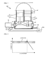
- FIG. 1 is a view of a stirling engine according to a first embodiment
- FIG. 2 is an explanatory view of a predetermined value in the first embodiment
- FIG. 3 is a view of control operation in the first embodiment
- FIG. 4 is a view of a stirling engine according to a second embodiment
- FIG. 5 is a view of a stirling engine according to a third embodiment
- FIG. 6 is a view of a first concrete example of a cooling portion
- FIG. 7 is a view of a second concrete example of the cooling portion
- FIG. 8 is an explanatory view of a change in state at the time of an engine warming-up
- FIG. 9 is an explanatory view of a change in state at the time when a cooler starts cooling
- FIG. 10 is a view of a stirling engine according to a fourth embodiment
- FIG. 11 is a view of control operation in the fourth embodiment
- FIG. 12 is a view of a stirling engine according to a fifth embodiment
- FIG. 13 is a view of a stirling engine according to a sixth embodiment
- FIG. 14 is a view of control operation in the sixth embodiment
- FIG. 15 is a view of a stirling engine according to a seventh embodiment
- FIG. 16 is a view of a predetermined valve in the seventh embodiment
- FIG. 17 is a view of control operation in the seventh embodiment
- FIG. 18 is a view of a stirling engine according to an eighth embodiment.
- FIG. 19 is a view of control operation in the eighth embodiment.
- FIG. 20 is a view of a relationship between a heat receiving period and a heat receiving amount.
- FIG. 1 is a view of a stirling engine 10 A.
- the stirling engine 10 A is a multicylinder ⁇ type (herein, two cylinders).
- the stirling engine 10 A is provided with a high-temperature-side cylinder 20 and a low-temperature-side cylinder 30 which are linearly and parallel arranged with each other. Also, a cooler 45 , a regenerator 46 , and a heater 47 are provided.
- the high-temperature-side cylinder 20 includes an expansion piston 21 and a high-temperature side cylinder 22
- the low-temperature-side cylinder 30 includes a compression piston 31 and a low-temperature side cylinder 32 .
- a space at the upper side of the high-temperature side cylinder 22 serves as an expansion space.
- Working fluid heated by the heater 47 circulates into the expansion space.
- the heater 47 exchanges heat between the circulating working fluid and exhaust gas of the internal combustion engine. Therefore, the working fluid is heated with heat energy collected from the exhaust gas.
- the exhaust gas of the internal combustion engine serves as a high temperature heat source.
- a space at the upper side of the low-temperature side cylinder 32 serves as a compression space.
- the working fluid cooled by the cooler 45 circulates into the compression space.
- the cooler 45 cools the working fluid by exchanging heat between the cooler 45 and a coolant as a cooling medium.
- the regenerator 46 transfers and receives heat to and from the working fluid reciprocating between the expansion and compression spaces. Specifically, the regenerator 46 receives heat from the working fluid when the working fluid circulates from the expansion space to the compression space.
- the regenerator 46 transfers the stored heat to the working fluid when the working fluid circulates from the compression space to the expansion space.
- the air is employed as the working fluid. However, the working fluid is not limited to the air. For example, gas such as He, H2, or N2 is applicable to the working fluid.
- the heater 47 heats the working fluid, so that the working fluid expands to press down the expansion piston 21 .
- the working fluid is fed to the regenerator 46 through the heater 47 .
- the working fluid releases heat in the regenerator 46 and circulates into the cooler 45 .
- the working fluid cooled in the cooler 45 circulates into the compression space, and then is compressed by the upper movement of the compression piston 31 .
- the working fluid which has been compressed in such a way increases its temperature while depriving heat from the regenerator 46 , and then circulates into the heater 47 .
- the working fluid is heated and expanded again.
- the stirling engine 10 A the working fluid reciprocating between the expansion and compression spaces performs the expansion work. Therefore, the cooler 45 cools the working fluid reciprocating between the expansion and compression spaces to cool the working fluid performing the expansion work.
- the stirling engine 10 A is capable of circulating the common coolant to the corresponding internal combustion engine to the cooler 45 . As described, the coolant starts circulating to the cooler 45 before the stirling engine 10 A starts (for example, at the time when the corresponding internal combustion engine starts).
- the gas lubrication is performed between the pistons 21 and 31 and the cylinders 22 and 32 , respectively.
- the pistons 21 and 31 are floated in the air by utilizing the air pressure (distribution) generated between the minute clearances between the pistons 21 and 31 and the cylinders 22 and 32 , respectively.
- the sliding resistance of the gas lubrication is very small, thereby significantly reducing the internal friction within the stirling engine 10 A.
- the gas lubrication causing an object to float in the air may employ, for example, specifically, static pressure gas lubrication in which a pressurized fluid is ejected to generate static pressure for floating the object.
- the gas lubrication is not limited to this, and may be dynamic pressure gas lubrication.
- the stirling engine 10 A further includes a crankshaft 61 and a crankcase 62 .
- the crankshaft 61 converts the reciprocating movements of the pistons 21 and 31 into a rotational movement.
- the crankshaft 61 provides a phase difference between the pistons 21 and 31 .
- the crankshaft 61 is provided in the crankcase 62 .
- the crankcase 62 houses a crank portion of the crankshaft 61 .
- the stirling engine 10 A further includes a pressure pump 65 , a pressure pipe 66 , and a pressure opening and closing valve 67 .
- the pressure pump 65 pressurizes the inside of the crankcase 62 . Specifically, the pressure pump 65 takes the air from the outside, pressures the air, and supplies the air to the crankcase 62 so as to pressurize the crankcase 62 .
- the pressure pipe 66 connects the crankcase 62 with the pressure pump 65 .
- the pressure opening and closing valve 67 is provided in the pressure pipe 66 , and permits or prohibits the pressurization of the inside of the crankcase 62 .
- the stirling engine 10 A even when the inside of the crankcase 62 is pressurized, the average pressure force of the working fluid in the expansion and compression spaces is substantially equal to the average pressure force of the working fluid within the crankcase 62 as time advances, through the minute clearances between the pistons 21 and 31 and the cylinders 22 and 32 , respectively. For this reason, in the stirling engine 10 A, the inside of the crankcase 62 is pressurized to make the working fluid to have high pressure, thereby ensuring the great output.
- the stirling engine 10 A further includes a starter 70 , a hygrometer 80 , and an ECU 90 A.
- the starter 70 drives the crankshaft 61 to assist the start of the stirling engine 10 A.
- the hygrometer 80 is provided in the crankcase 62 , and measures the humidity within the crankcase 62 (the internal humidity, within the crankcase 62 , of the stirling engine 10 A).
- the crankcase 62 corresponds to a predetermined portion in the stirling engine 10 A.
- the ECU 90 A is an electronic control unit.
- the ECU 90 A is electrically connected to a controlled object such as the starter 70 , and sensors or switches such as the pressure pump 65 , the pressure opening and closing valve 67 , and the hygrometer 80 .
- a CPU processes based on a program stored in a ROM and uses a temporary memory area of a RAM if necessary, so that various function units such as a control unit as will be described below is achieved.
- the control unit adjusts the start timing based on the internal humidity of the stirling engine 10 A.
- the control unit adjusts the start timing based on the humidity within the crankcase 62 .
- the control unit performs the start, when the humidity within the crankcase 62 is lower than a predetermined value ⁇ .
- the control unit drives the starter 70 for performing the start.
- the stirling engine 10 A is provided with the ECU 90 A achieving the control unit, thereby performing these control processes.
- FIG. 2 is an explanatory view of the predetermined value ⁇ .
- the vertical axis indicates a humidity
- the horizontal axis indicates an elapsed time.
- the humidity indicated by the vertical axis represents the internal humidity, at the cooler 45 through which the coolant circulates, of the stirling engine 10 A.
- FIG. 2 it can be understood that when the humidity is 100 percent before the start is performed, the condensation will occur within the cooler 45 . In this case, when the humidity changes to be lower than 100%, it can be understood that the working fluid is heated by the heater 47 as time advances, so that condensation does not occur within the cooler 45 .
- a temperature of the working fluid within the cooler 45 is different from that of the working fluid within the crankcase 62 , where the humidity is actually measured by the hygrometer 80 .
- the cooler 45 is also apart from the crankcase 62 .
- the predetermined value ⁇ can be set smaller than 100 percent by a humidity difference which can occur between them at the time when the humidity within the cooler 45 through which the coolant circulates is lower than 100 percent. Also, the predetermined value ⁇ can be set smaller by a measurement error caused by the hygrometer 80 itself.
- step S 1 The ECU 90 A measures the humidity (step S 1 ).
- step S 2 it is determined whether or not the measured humidity is lower than the predetermined value ⁇ .
- step S 3 the ECU 90 A performs the start (step S 3 ).
- step S 3 specifically, the ECU 90 A drives the starter 70 . Additionally, the start may be performed in step S 3 when another start condition is satisfied (for example, whether or not the stirling engine 10 A is capable of driving independently). This flowchart finishes after step S 3 .
- the stirling engine 10 A adjusts the start timing based on the humidity within the crankcase 62 . It is therefore possible to perform the start in the state where condensation does not occur within the cooler 45 which most reduces the temperature of the working fluid. For this reason, the stirling engine 10 A can improve so that the gas lubrication is not disturbed by condensed water. This prevents or suppresses, specifically, an increase in friction and damage of sliding portions.
- the start is performed when the humidity within the crankcase 62 is lower than the predetermined value ⁇ . It is thus possible to perform the start in the state where condensation does not occur within the cooler 45 .
- the stirling engine 10 A is suitable for pressurizing the inside thereof by pressurizing the inside of the crankcase 62 .
- the stirling engine 10 A In the stirling engine 10 A, the air containing moisture serves as the working fluid, resulting in the gas lubrication tends to be disturbed by condensed water. Therefore, the stirling engine 10 A is suitable for employing the air as the working fluid.
- the stirling engine 10 A is suitable for being provided with the pressure pump 65 , which takes the air from the outside and pressure supplies the air to the inside so as to pressure the inside, and in addition, moisture contained in the working fluid tends to be condensed when the inside is pressured.
- FIG. 4 is a view of a stirling engine 10 B.
- the stirling engine 10 B is the substantially the same as the stirling engine 10 A, except that the hygrometer 80 is provided in the cooler 45 and an ECU 90 B is provided instead of the ECU 90 A.
- the hygrometer 80 measures the humidity within the cooler 45 (the internal humidity, at the cooler 45 , of the stirling engine 10 B).
- the cooler 45 corresponds to a predetermined portion.
- the ECU 90 B is substantially the same as the ECU 90 A, except that a control unit is achieved as follows. Specifically, in a case where, in the ECU 90 B, the control unit adjusts the start timing based on the internal humidity, the start timing is adjusted based on the humidity within the cooler 45 . Therefore, the start is performed when the humidity within the cooler 45 is lower than a predetermined value ⁇ . In a case where the humidity within the cooler 45 is higher than or equal to the predetermined value ⁇ , the start is performed when the humidity is lower than the predetermined value ⁇ .
- the predetermined value ⁇ is set to 100 percent.
- the predetermined value ⁇ can be set smaller by a measurement error caused by the hygrometer 80 itself.
- control operation of the stirling engine 10 B is the same as the control operation of the stirling engine 10 A illustrated in FIG. 3 .
- illustration of a flowchart of the control operation of the stirling engine 10 B is omitted.
- the predetermined value ⁇ is applied instead of the predetermined value ⁇ , in step S 2 .
- the start timing is adjusted based on the humidity in the cooler 45 , whereby it can be directly determined whether or not condensation occurs in the cooler 45 .
- the stirling engine 10 B is suitable for performing the start earlier than the stirling engine 10 A, because the suitable start timing can be determined with accuracy in order the improvement to be achieved such that the gas lubrication is not disturbed by condensed water.
- FIG. 5 is a view of a stirling engine 10 C.
- the stirling engine 10 C is substantially the same as the stirling engine 10 A, except that a cooling portion 100 is further provided.
- a similar variation is applicable to the stirling engine 10 B.
- the cooling portion 100 is provided within the crankcase 62 , and further reduces the temperature of the working fluid as compared with the cooler 45 .
- FIG. 6 is a view of a first concrete example of the cooling portion 100 .
- a cooling device 200 illustrated in FIG. 6 includes a compressor 201 , a condensing portion 202 , an evaporating portion 203 , and a drive motor 204 .
- the compressor 201 compresses a cooling medium F.
- the cooling medium F compressed by the compressor 201 condenses in the condensing portion 202 to release heat.
- the cooling medium F condensed in the condensing portion 202 expands, and then evaporates in the evaporating portion 203 to receive heat.
- the drive motor 204 drives the compressor 201 .
- the cooling portion 100 is achieved by the evaporating portion 203 of the cooling device 200 , whereby the cooling portion 100 serves as a cooling portion capable of cooling by use of vaporization heat of the cooling medium F.
- FIG. 7 is a view of a second concrete example of the cooling portion 100 .
- a cooling device 300 illustrated in FIG. 7 includes a direct current power supply 301 , a p-type semiconductor 302 , an n-type semiconductor 303 , electrodes 304 and 305 , and a switch 306 .
- the semiconductors 302 and 303 joined with the electrode 305 are connected with the direct current power supply 301 through the switch 306 .
- heat is adsorbed at one side of the electrodes (herein, the electrode 304 side) and heat is generated at the other side of the electrodes (herein, the electrode 305 side), that is, Peltier effect occurs.
- the cooling portion 100 is achieved by a semiconductor unit including the semiconductors 302 and 303 and the electrodes 305 and 306 of the cooling device 300 , whereby the cooling portion 100 serves as a cooling portion capable of cooling by use of the heat adsorption of Peltier effect.
- the cooling portion 100 causes condensation to occur so as to reduce moisture contained in the working fluid. This brings dehumidification effect.
- the cooling portion 100 also corresponds to a dehumidifying portion.
- the dehumidifying portion which reduce the internal humidity of the stirling engine 10 C is not limited to the cooling portion 100 .
- a dehumidifier which can dehumidify by use of a dehumidifying agent may be provided within the crankcase 62 .
- the dehumidifying portion may be provided within the pressure pipe 66 to dehumidify the air introduced into the stirling engine 10 C.
- such a dehumidifying portion may be achieved by a dehumidifier which can dehumidify by use of a dehumidifying agent.
- FIG. 8 is an explanatory view of a change in state at the time of the engine warming-up.
- the vertical axis indicates an amount of water vapor, and the horizontal axis indicates time.
- a pattern A corresponds to the stirling engine 10 C.
- a pattern A′ corresponds to a case where the cooling portion 100 does not cool.
- a point P1 indicates a predetermined amount of the water vapor included in the working fluid after the warming up, by corresponding the amount of the water vapor corresponding to a cooling temperature of the cooler 45 .
- Points P2 and P2′ indicates positions where condensation disappears.
- Points P3 and P3′ indicates positions where the warming up finishes.
- a curve C1 is a saturated vapor curve.
- the stirling engine 10 C is provided with the cooling portion 100 within the crankcase 62 so as to cause condensation to occur in the cooling portion 100 .
- dehumidification accelerates a reduction in humidity within the cooler 45 .
- This can make the temperature when condensation disappears in the pattern A lower than that in the pattern A′.
- the stirling engine 10 C is suitable for performing the start early, because accelerating a reduction in humidity within the cooler 45 as compared with the stirling engine 10 A.
- FIG. 9 is an explanatory view of a change in state at the time when the cooler 45 starts cooling.
- the vertical axis indicates an amount of water vapor.
- the horizontal axis indicates time.
- a pattern B corresponds to the stirling engine 10 C.
- a pattern B′ corresponds to a case where the cooling portion 100 does not cool.
- a point P11 indicates a position before the start is performed.
- a point P12 indicates a position where an amount of water vapor is reduced in a case where the cooling portion 100 cools, while corresponding to the point P11.
- Points P13 and P13′ indicates positions when the start is performed.
- a curve C1 is a saturated vapor curve.
- the cooling is performed in the cooling portion 100 by the stirling engine 10 C before the start is performed, whereby it is possible to reduce the humidity within the cooler 45 .
- the coolant starts circulating through the cooler 45 at the same time of starting the stirling engine 10 C, the occurrence of the condensation in the cooler 45 itself can be prevented.
- FIG. 10 is a view of a stirling engine 10 D.
- the stirling engine 10 D is substantially the same as the stirling engine 10 C, except that an operation control portion 101 controls the operation of the cooling portion 100 is provided, and an ECU 90 C is provided instead of the ECU 90 A.
- the ECU 90 C is substantially the same as the ECU 90 A, except that the operation control portion 101 is electrically connected with the ECU 90 C, and the control unit is achieved below.
- a similar variation is applicable to the stirling engine 10 B which is further provided with the cooling portion 100 .
- the control unit is achieved to operate the cooling portion 100 based on the humidity within the crankcase 62 . Specifically, when the humidity within the crankcase 62 is higher than the predetermined value ⁇ (specifically, is equal to or higher than the predetermined value ⁇ ), the control unit operates the cooling portion 100 . Also, when the humidity within the crankcase 62 is lower than the predetermined value ⁇ , the cooling portion 100 stops. Additionally, in a case where a similar variation is applied to the stirling engine 10 B which is further provided with the cooling portion 100 , the humidity within the crankcase 62 corresponds to the humidity within the cooler 45 , and the predetermined value ⁇ corresponds to the predetermined value ⁇ .
- the control unit operates the cooling portion 100 by controlling the operation control portion 101 .
- the operation control portion 101 is achieved below.
- the operation control portion 101 can be achieved by the drive motor 204 .
- the operation control portion 101 can be achieved by the switch 306 .
- the ECU 90 C measures the humidity (step S 11 ), and determines whether or not the humidity is in the state where the start can be performed (step S 12 ). If a negative determination is made in step S 12 , the ECU 90 C operates the cooling portion 100 (step S 13 ). Subsequently, the ECU 90 C measures the humidity (step S 14 ), and determines whether or not the measured humidity is in the state where the start can be performed (step S 15 ). Additionally, in steps S 12 and S 15 , specifically, it is determined whether or not the measured humidity is lower than the predetermined value ⁇ .
- step S 15 If a negative determination is made in step S 15 , the process returns to step S 13 . Thus, until the measured humidity is smaller than the predetermined value ⁇ , the operation of the cooling portion 100 continues. On the other hand, if a positive determination is made in step S 15 , the ECU 90 C stops the operation of the cooling portion 100 (step S 16 ). Subsequently, the start is performed (step S 17 ), after step S 16 , or after a positive determination is made in step S 12 . Additionally, the start may be performed in step S 17 , when another start condition is satisfied. This flowchart finishes after step S 17 .
- the cooling portion 100 is operated based on the humidity within the crankcase 62 , whereby the cooling portion 100 can be operated in the range where dehumidification is effective for making start timing early. This can also suppress waste of energy used for the operation of the cooling portion 100 .
- the cooling portion 100 when the humidity within the crankcase 62 is higher than the predetermined value ⁇ , the cooling portion 100 operates, and when the humidity within the crankcase 62 is lower than the predetermined value ⁇ , the cooling portion 100 stops. It is therefore possible to operate the cooling portion 100 in the range where dehumidification is effective for making the start timing early.
- FIG. 12 is a view of a stirling engine 10 E.
- the stirling engine 10 E is substantially the same as the stirling engine 10 C, except that a partition wall portion 102 is further provided around the cooling portion 100 within the crankcase 62 .
- a similar variation is applicable to the stirling engine 10 D or the stirling engine 10 B which is further provided with the cooling portion 100 .
- the partition wall portion 102 is provided with a ventilation portion around the cooling portion 100 in such a manner that the air can blow into the cooling portion 100 .
- the partition wall portion 102 may be formed as a part of the crankcase 62 .
- the stirling engine 10 E Effects of the stirling engine 10 E will be described next.
- the provision of the partition wall portion 102 can prevent or suppress water condensed in the cooling portion 100 from being scattered by vibration or the like and infiltrating between the piston 21 and the cylinder 22 or between the piston 31 and the cylinder 32 .
- this stirling engine 10 E improves such that the gas lubrication is not disturbed by condensed water in a highly suitable manner, as compared with the stirling engine 10 C.
- FIG. 13 is a view of a stirling engine 10 F.
- the stirling engine 10 F is substantially the same as the stirling engine 10 A, except that a control valve 110 which is capable of controlling the supply of the coolant to the cooler 45 is provided, an actuator 111 for the control valve 110 is provided, and an ECU 90 D is provided instead of the ECU 90 A.
- the ECU 90 D is substantially the same as the ECU 90 A, except that the actuator 111 as an controlled object is electrically connected to the ECU 90 D, and the control unit is achieved as follows.
- a similar variation is applicable to the stirling engines 10 B, 10 C, 10 D and 10 E.
- the control unit is achieved to control the control valve 110 to restricts the circulation of the coolant before the start (herein, specifically, the control valve 110 is closed).
- the control valve 110 in the control valve 110 , unless the control unit controls the control valve 110 to restrict the circulation of the coolant before the start, the control valve 110 remains in a state of releasing the restriction of the circulation of the coolant before the start (specifically, the valve is in an open state). This releases the restriction of the circulation of the coolant to the cooler 45 before the start. That is, herein, specifically, the coolant starts circulating to the cooler 45 before the start.
- the control unit controls the control valve 110 to restrict the circulation of the coolant, thereby controlling the control valve 110 to restrict the circulation of the coolant before the start.
- the control unit controls the control valve 110 to release the restriction of the circulation of the coolant (specifically, herein, the control valve 110 opens).
- the control unit controls the actuator 111 to the control valve 110 .
- the ECU 90 D measures the humidity (step S 21 ), and determines whether or not the humidity is in a state where the start can be performed (step S 22 ). If a negative determination is made in step S 22 , the ECU 90 D controls the control valve 110 to close (step S 23 ). Subsequently, the ECU 90 D measures the humidity (step S 24 ), and determines whether or not the humidity is in the state where the start can be performed (step S 25 ). Additionally, specifically, it is determined whether or not the measured humidity is lower than predetermined value ⁇ in steps S 22 and S 25 .
- step S 25 If a negative determination is made in step S 25 , the process returns to step S 23 . Thus, until the measured humidity is lower than the predetermined value ⁇ , the control valve 110 continues closing. On the other hand, if a positive determination is made in step S 25 , the ECU 90 D controls the control valve 110 to open (step S 26 ). Subsequently, the ECU 90 D performs the start (step S 27 ), after step S 26 , or after a positive determination is made in step S 22 . Also, the start may be performed in step S 27 , when another start condition is satisfied. This flowchart finishes after step S 27 .
- the control valve 110 is controlled to restrict the circulation of the coolant before the start, thereby reducing the cooling ability of the cooler 45 . This accelerates the warming up to reduce the humidity within the cooler 45 early.
- this stirling engine 10 F is suitable for making the start timing early, because accelerating a reduction in humidity in the cooler 45 as compared with the stirling engine 10 A.
- the control valve 110 when the humidity within the crankcase 62 is higher than the predetermined value ⁇ , the control valve 110 is controlled to restrict the circulation of the coolant, and when the humidity within the crankcase 62 is lower than the predetermined value ⁇ , the control valve 110 is controlled to release the restriction of the circulation of the coolant. It is therefore possible to reduce the cooling ability of the cooler 45 in the range where making the start timing early is effective in terms of condensation.
- FIG. 15 is a view of a stirling engine 10 G.
- the stirling engine 10 G is substantially the same as the stirling engine 10 A, except that a thermometer 85 is provided instead of the hygrometer 80 , an ECU 90 E is provided instead of the ECU 90 A.
- the ECU 90 E is substantially the same as the ECU 90 A, except that the thermometer 85 instead of the hygrometer 80 is electrically connected to the ECU 90 E, and the control unit is achieved as follows.
- a similar variation is applicable to the stirling engines 10 C, 10 D, 10 E and 10 F.
- the thermometer 85 is provided in the cooler 45 .
- the thermometer 85 detects the temperature of the working fluid in the cooler 45 .
- the control unit adjusts the start timing based on the temperature of the working fluid in the cooler 45 .
- the control unit performs the start.
- the predetermined value ⁇ is a desired temperature, and is set to the boiling point of the coolant.
- FIG. 16 is an explanatory view of the predetermined value ⁇ .
- the vertical axis indicates a pressure force, and the horizontal axis indicates a temperature.
- a curve C2 is a saturated vapor curve. Each temperature on the horizontal axis indicates the boiling points. The boiling point changes along the curve C2 with the pressure force as illustrated in FIG. 16 .
- the predetermined valve ⁇ is set under the conditions under which the internal pressure is constant in the stirling engine 10 G.
- the predetermined value ⁇ may be a variable value in accordance with the internal pressure of the stirling engine 10 G.
- a pressure sensor can detect the internal pressure of the stirling engine 10 G.
- the ECU 90 E measures the temperature of the working fluid in the cooler 45 (step S 31 ), and determines whether or not the temperature is in the state where the start can be performed (step S 32 ). Specifically, it is determined whether or not the measured temperature is higher than the predetermined value ⁇ in step S 32 . If a negative determination is made in step S 32 , the process returns to step S 31 . If a positive determination is made in step S 32 , the ECU 90 E performs the start (step S 33 ). Additionally, in step S 33 , the start may be performed when another start condition is satisfied. This flowchart finishes after step S 33 .
- the stirling engine 10 G adjusts the start timing based on the temperature of the working fluid in the cooler 45 . Specifically, the start is performed when the temperature of the working fluid in the cooler 45 is higher than the predetermined value ⁇ , and the predetermined value ⁇ is set to the boiling point of the coolant. Therefore, in a case where the stirling engine 10 G adjusts the start timing based on the internal humidity, it is possible to perform the start in the state where condensation does not occur, even when the internal humidity in a predetermined portion is not detected especially. As a result, the improvement is achieved so that the gas lubrication is not disturbed by condensed water.
- FIG. 18 is a view of a stirling engine 10 H.
- the stirling engine 10 H is substantially the same as the stirling engine 10 F, except that the hygrometer 80 is not especially provided, and an ECU 90 F is provided instead of the ECU 90 D.
- the ECU 90 F is substantially the same as the ECU 90 D, except that a detector 86 instead of the hygrometer 80 is electrically connected, and the control unit is achieved as follows.
- a similar variation is applicable to the stirling engine 10 C, 10 D, and 10 E which are further provided with the control valve 110 and the actuator 111 if necessary.
- the detector 86 is configured to include sensors and switches for detecting the driving state of the corresponding internal combustion engine.
- the detector 86 includes an airflow meter for measuring an intake air amount of the internal combustion engine, a crank angle sensor for detecting a rotational speed of the internal combustion engine, an acceleration opening sensor for detecting an operation amount of an accelerate pedal (an acceleration opening) used for accelerating the internal combustion engine, and an ignition switch for starting the internal combustion engine.
- the ECU 90 F can detects the start timing and a fuel injection amount (an opening period of a fuel injection valve) of the corresponding internal combustion engine based on the outputs from the detector 86 .
- the ECU 90 F may intercommunicate with an ECU, instead of the detector 86 , for controlling the internal combustion engine.
- the ECU 90 F may be for controlling the internal combustion engine.
- the control unit adjusts the start timing based on a heat receiving period.
- the control unit performs the start at the time when the heat receiving period is longer than a predetermined period T.
- the predetermined period T is set a period when the temperature of the working fluid in the cooler 45 is higher than the predetermined value ⁇ .
- the predetermined period T is calculated (estimated) to be set as follows.
- the control unit calculates and integrates the exhaust heat capacity of the corresponding internal combustion engine. Subsequently, a temperature increasing rate of the working fluid is calculated based on an integrated value of the exhaust heat and the heat capacity of the striling engine 10 H (whole heat capacity of heat receiving portions including the working fluid in consideration of a heat exchange ability of the heater 47 and heat received in another than the working fluid which transfers heat). Further, the predetermined period T is calculated based on the calculated temperature increasing rate and the predetermined value ⁇ as the desired temperature. Whenever the control unit calculates the integrated value of the exhaust heat capacity, the predetermined valve T is calculated to be updated.
- the exhaust heat capacity can be calculated based on the intake air amount and the fuel injection amount of the corresponding internal combustion engine.
- the temperature increasing rate can be calculated by dividing the heat capacity of the stirling engine 10 H by the exhaust heat capacity.
- the predetermined period T can be calculated by dividing the predetermined value ⁇ by the temperature increasing rate. In a case where the predetermined period T is calculated in such a way, the control unit controls the control valve 110 to close when the corresponding internal combustion engine starts at the latest, and controls the control valve 110 to open when the stirling engine 10 H starts.
- the ECU 90 F determines whether or not the corresponding internal combustion engine starts (step S 41 ). If a negative determination is made, the process returns to step S 41 . If a positive determination is made, the ECU 90 F starts measuring the heat receiving period (step S 42 ). Also, the control valve 110 closes (step S 43 ). Subsequently, the ECU 90 F calculates and integrates the exhaust heat capacity (step S 44 ). Further, the temperature increasing rate of the working fluid is calculated (step S 45 ).
- step S 46 calculates the predetermined period T (step S 46 ), and determines whether or not the heat receiving period when the start can be performed elapses (step S 47 ). Specifically, in step S 47 , it is determined whether or not the heat receiving period is longer than the predetermined period T. If a negative determination is made in step S 47 , the process returns to step S 44 . Therefore, until a positive determination is made in step S 47 , whenever the integrated value of the exhaust heat capacity is calculated in step S 44 , the new predetermined period T is calculated in step S 46 . As a result, the predetermined period T is updated. If a positive determination is made in step S 47 , the ECU 90 F performs the start (step S 48 ). Also, the control valve 110 opens (step S 49 ). Additionally, the start may be performed when another start condition is formed in step S 48 . This flowchart finishes after step S 49 .
- the stirling engine 10 H adjusts the start timing based on the heat receiving period. Specifically, the start is performed when the heat receiving period is longer than the predetermined period T, and the predetermined period T is set to a period when the temperature of the working fluid in the cooler 45 is higher than the predetermined value ⁇ . Therefore, in a case where the stirling engine 10 H adjusts the start timing based on the internal humidity, the start can be performed in the state where the condensation does not occur in the cooler 45 without detecting the internal humidity in the predetermined portion. Accordingly, the improvement is achieved so that the gas lubrication is not disturbed by condensed water.
- the control valve 110 closes at the latest time of the start of the corresponding internal combustion, thereby stopping the cooling of the cooler 45 . This accelerates the warming up to make the start timing early. Additionally, in a case where the start timing is adjusted based on the heat receiving period, the coolant may circulate through the cooler 45 in the stirling engine 10 H. In this case, the predetermined period T is calculated in consideration of the cool by the cooler 45 .
- FIG. 20 is a view of a relationship between the heat receiving period and the heat receiving amount.
- the vertical axis indicates a heat receiving amount
- the horizontal axis indicates a heat receiving period.
- the heat receiving period is longer than the predetermined period T, and then the heat receiving amount is higher than the desired heat amount H, whereby it is possible to start the stirling engine 10 H.
- the stirling engine 10 H adjusts the start timing based on the internal humidity
- the start timing may be adjusted based on the heat receiving amount.
- the start is performed when the heat receiving amount is higher than the desired heat amount H as a predetermined amount, and such a predetermined amount can be set to an amount (heat receiving amount corresponding to the predetermined period T) where the temperature of the working fluid in the cooler 45 is higher than the predetermined value ⁇ .
- the stirling engine is not always limited to the internal combustion engine, and may collect heat released from an arbitrary configuration such as a gas turbine.
- the predetermined portion is not always limited to the crankcase or the cooler.
- the predetermined portion in a case where the predetermined portion is the crankcase, it is suitable for, for example, setting the hygrometer therein with ease.
- the predetermined portion in a case where the predetermined portion is the cooler, it is suitable for directly determining whether or not the cooler is in the state where condensation occurs therein.
Landscapes
- Engineering & Computer Science (AREA)
- Chemical & Material Sciences (AREA)
- Combustion & Propulsion (AREA)
- Mechanical Engineering (AREA)
- General Engineering & Computer Science (AREA)
- Devices That Are Associated With Refrigeration Equipment (AREA)
- Lubrication Of Internal Combustion Engines (AREA)
- Engine Equipment That Uses Special Cycles (AREA)
Applications Claiming Priority (1)
| Application Number | Priority Date | Filing Date | Title |
|---|---|---|---|
| PCT/JP2011/075314 WO2013065148A1 (ja) | 2011-11-02 | 2011-11-02 | スターリングエンジン |
Publications (2)
| Publication Number | Publication Date |
|---|---|
| US20140230428A1 US20140230428A1 (en) | 2014-08-21 |
| US9222435B2 true US9222435B2 (en) | 2015-12-29 |
Family
ID=48191541
Family Applications (1)
| Application Number | Title | Priority Date | Filing Date |
|---|---|---|---|
| US13/579,652 Expired - Fee Related US9222435B2 (en) | 2011-11-02 | 2011-11-02 | Stirling engine with humidity control |
Country Status (5)
| Country | Link |
|---|---|
| US (1) | US9222435B2 (ja) |
| JP (1) | JP5316722B1 (ja) |
| CN (1) | CN103210199B (ja) |
| DE (1) | DE112011105796B4 (ja) |
| WO (1) | WO2013065148A1 (ja) |
Families Citing this family (3)
| Publication number | Priority date | Publication date | Assignee | Title |
|---|---|---|---|---|
| GB201016522D0 (en) * | 2010-10-01 | 2010-11-17 | Osborne Graham W | Improvements in and relating to reciprocating piston machines |
| CN103925112B (zh) * | 2014-04-30 | 2015-08-19 | 郭远军 | 一种直列式热能动力设备及其做功方法 |
| US10781771B1 (en) * | 2019-09-22 | 2020-09-22 | Ghasem Kahe | Automatic cooling system for combustion engine |
Citations (20)
| Publication number | Priority date | Publication date | Assignee | Title |
|---|---|---|---|---|
| US2643509A (en) * | 1945-06-28 | 1953-06-30 | Joris Daniel Heijligers | Method and system for braking hotgas piston engines and for utilizing heat generated thereby in operation thereof |
| US4387568A (en) * | 1980-07-14 | 1983-06-14 | Mechanical Technology Incorporated | Stirling engine displacer gas bearing |
| US4881372A (en) * | 1988-02-29 | 1989-11-21 | Aisin Seiki Kabushiki Kaisha | Stirling engine |
| US4969333A (en) * | 1988-12-16 | 1990-11-13 | Sanyo Electric Co., Ltd. | Heat pump apparatus |
| JPH05172058A (ja) | 1991-12-20 | 1993-07-09 | Mitsubishi Electric Corp | 油はねあがり防止装置 |
| JPH09264192A (ja) | 1995-10-30 | 1997-10-07 | Shigefumi Mori | スターリングエンジンにおける効率向上装置 |
| US5987886A (en) * | 1996-11-15 | 1999-11-23 | Sanyo Electric Co., Ltd. | Stirling cycle engine |
| JP2001153478A (ja) * | 1999-11-30 | 2001-06-08 | Sanyo Electric Co Ltd | 冷凍装置 |
| JP2003294333A (ja) * | 2002-04-02 | 2003-10-15 | Sharp Corp | スターリング機関 |
| US20040154297A1 (en) * | 2003-02-10 | 2004-08-12 | Jonathan Strimling | Coolant penetrating cold-end pressure vessel |
| JP2005113719A (ja) | 2003-10-03 | 2005-04-28 | Honda Motor Co Ltd | 内燃機関とスターリング機関とを備える動力装置 |
| US20070277521A1 (en) * | 2004-06-03 | 2007-12-06 | Shohzoh Tanaka | Stirling Engine |
| US20080163620A1 (en) * | 2007-01-09 | 2008-07-10 | Toyota Jidosha Kabushiki Kaisha | Stirling engine and control method therefor |
| JP2008267258A (ja) | 2007-04-19 | 2008-11-06 | Toyota Motor Corp | 排熱回収機関及び運転制御装置 |
| JP2009091959A (ja) | 2007-10-05 | 2009-04-30 | Toyota Motor Corp | 排熱回収機関及び起動制御装置 |
| JP2010222992A (ja) | 2009-03-19 | 2010-10-07 | Toyota Motor Corp | スターリングエンジンのピストンの気体潤滑構造 |
| JP2011074853A (ja) | 2009-09-30 | 2011-04-14 | Honda Motor Co Ltd | 内燃機関のクランクケース構造 |
| JP2011099384A (ja) | 2009-11-06 | 2011-05-19 | Toyota Motor Corp | スターリングエンジン |
| JP2011149385A (ja) | 2010-01-25 | 2011-08-04 | Toyota Motor Corp | 冷却水循環装置 |
| US20110232276A1 (en) * | 2010-03-26 | 2011-09-29 | Toyota Jidosha Kabushiki Kaisha | Stirling engine and control method thereof |
Family Cites Families (2)
| Publication number | Priority date | Publication date | Assignee | Title |
|---|---|---|---|---|
| JP2006348893A (ja) * | 2005-06-17 | 2006-12-28 | Toyota Motor Corp | 熱機関 |
| JP4872816B2 (ja) * | 2007-06-12 | 2012-02-08 | トヨタ自動車株式会社 | ピストン装置及び排熱回収装置 |
-
2011
- 2011-11-02 DE DE112011105796.2T patent/DE112011105796B4/de not_active Expired - Fee Related
- 2011-11-02 US US13/579,652 patent/US9222435B2/en not_active Expired - Fee Related
- 2011-11-02 CN CN201180011898.7A patent/CN103210199B/zh not_active Expired - Fee Related
- 2011-11-02 JP JP2012529834A patent/JP5316722B1/ja not_active Expired - Fee Related
- 2011-11-02 WO PCT/JP2011/075314 patent/WO2013065148A1/ja active Application Filing
Patent Citations (21)
| Publication number | Priority date | Publication date | Assignee | Title |
|---|---|---|---|---|
| US2643509A (en) * | 1945-06-28 | 1953-06-30 | Joris Daniel Heijligers | Method and system for braking hotgas piston engines and for utilizing heat generated thereby in operation thereof |
| US4387568A (en) * | 1980-07-14 | 1983-06-14 | Mechanical Technology Incorporated | Stirling engine displacer gas bearing |
| US4881372A (en) * | 1988-02-29 | 1989-11-21 | Aisin Seiki Kabushiki Kaisha | Stirling engine |
| US4969333A (en) * | 1988-12-16 | 1990-11-13 | Sanyo Electric Co., Ltd. | Heat pump apparatus |
| JPH05172058A (ja) | 1991-12-20 | 1993-07-09 | Mitsubishi Electric Corp | 油はねあがり防止装置 |
| JPH09264192A (ja) | 1995-10-30 | 1997-10-07 | Shigefumi Mori | スターリングエンジンにおける効率向上装置 |
| US5987886A (en) * | 1996-11-15 | 1999-11-23 | Sanyo Electric Co., Ltd. | Stirling cycle engine |
| JP2001153478A (ja) * | 1999-11-30 | 2001-06-08 | Sanyo Electric Co Ltd | 冷凍装置 |
| JP2003294333A (ja) * | 2002-04-02 | 2003-10-15 | Sharp Corp | スターリング機関 |
| US20040154297A1 (en) * | 2003-02-10 | 2004-08-12 | Jonathan Strimling | Coolant penetrating cold-end pressure vessel |
| JP2005113719A (ja) | 2003-10-03 | 2005-04-28 | Honda Motor Co Ltd | 内燃機関とスターリング機関とを備える動力装置 |
| US20070277521A1 (en) * | 2004-06-03 | 2007-12-06 | Shohzoh Tanaka | Stirling Engine |
| US20080163620A1 (en) * | 2007-01-09 | 2008-07-10 | Toyota Jidosha Kabushiki Kaisha | Stirling engine and control method therefor |
| JP2008267258A (ja) | 2007-04-19 | 2008-11-06 | Toyota Motor Corp | 排熱回収機関及び運転制御装置 |
| JP2009091959A (ja) | 2007-10-05 | 2009-04-30 | Toyota Motor Corp | 排熱回収機関及び起動制御装置 |
| JP2010222992A (ja) | 2009-03-19 | 2010-10-07 | Toyota Motor Corp | スターリングエンジンのピストンの気体潤滑構造 |
| JP2011074853A (ja) | 2009-09-30 | 2011-04-14 | Honda Motor Co Ltd | 内燃機関のクランクケース構造 |
| JP2011099384A (ja) | 2009-11-06 | 2011-05-19 | Toyota Motor Corp | スターリングエンジン |
| JP2011149385A (ja) | 2010-01-25 | 2011-08-04 | Toyota Motor Corp | 冷却水循環装置 |
| US20110232276A1 (en) * | 2010-03-26 | 2011-09-29 | Toyota Jidosha Kabushiki Kaisha | Stirling engine and control method thereof |
| JP2011202612A (ja) | 2010-03-26 | 2011-10-13 | Toyota Motor Corp | スターリングエンジン |
Also Published As
| Publication number | Publication date |
|---|---|
| DE112011105796T5 (de) | 2014-08-07 |
| JPWO2013065148A1 (ja) | 2015-04-02 |
| CN103210199A (zh) | 2013-07-17 |
| CN103210199B (zh) | 2015-06-17 |
| WO2013065148A1 (ja) | 2013-05-10 |
| JP5316722B1 (ja) | 2013-10-16 |
| US20140230428A1 (en) | 2014-08-21 |
| DE112011105796B4 (de) | 2021-06-10 |
Similar Documents
| Publication | Publication Date | Title |
|---|---|---|
| Verde et al. | Modelling of an adsorption system driven by engine waste heat for truck cabin A/C. Performance estimation for a standard driving cycle | |
| RU2626879C2 (ru) | Способ для двигателя (варианты) | |
| RU142007U1 (ru) | Система двигателя транспортного средства | |
| US9359936B2 (en) | System and operating method for a supercharged internal combustion engine with charge-air cooling | |
| JP2008544153A5 (ja) | ||
| JP5271961B2 (ja) | 内燃機関の過給装置 | |
| US9222435B2 (en) | Stirling engine with humidity control | |
| KR101944831B1 (ko) | 가스 히트펌프 | |
| WO2013046853A1 (ja) | 廃熱回生システム | |
| JP5950054B2 (ja) | 熱輸送装置 | |
| JP2018003682A (ja) | 排熱回収機能付きエンジン | |
| CN113811676B (zh) | 分体循环发动机 | |
| US10107236B2 (en) | Exhaust gas temperature regulation in a bypass duct of an exhaust gas recirculation system | |
| JP2018204490A (ja) | 吸気冷却システム | |
| JP2014141907A (ja) | 内燃機関 | |
| US20110232276A1 (en) | Stirling engine and control method thereof | |
| JP2005256806A (ja) | 内燃機関の吸気装置 | |
| WO2019073769A1 (ja) | 吸気冷却システム | |
| US20130019595A1 (en) | Control apparatus and control method for stirling engine | |
| US20070220881A1 (en) | External combustion engine | |
| JPH1122551A (ja) | エンジン駆動式熱ポンプ装置 | |
| JP2019100269A (ja) | 吸気冷却システム | |
| JP2014118866A (ja) | スターリングエンジン | |
| JPH11257154A (ja) | 外燃式熱ガス機関 | |
| US11519347B2 (en) | Gas engine heat pump and method of operating the same |
Legal Events
| Date | Code | Title | Description |
|---|---|---|---|
| AS | Assignment |
Owner name: TOYOTA JIDOSHA KABUSHIKI KAISHA, JAPAN Free format text: ASSIGNMENT OF ASSIGNORS INTEREST;ASSIGNORS:KOMORI, SATOSHI;KATAYAMA, MASAAKI;TATENO, MANABU;REEL/FRAME:028804/0421 Effective date: 20120612 |
|
| ZAAA | Notice of allowance and fees due |
Free format text: ORIGINAL CODE: NOA |
|
| ZAAB | Notice of allowance mailed |
Free format text: ORIGINAL CODE: MN/=. |
|
| STCF | Information on status: patent grant |
Free format text: PATENTED CASE |
|
| MAFP | Maintenance fee payment |
Free format text: PAYMENT OF MAINTENANCE FEE, 4TH YEAR, LARGE ENTITY (ORIGINAL EVENT CODE: M1551); ENTITY STATUS OF PATENT OWNER: LARGE ENTITY Year of fee payment: 4 |
|
| FEPP | Fee payment procedure |
Free format text: MAINTENANCE FEE REMINDER MAILED (ORIGINAL EVENT CODE: REM.); ENTITY STATUS OF PATENT OWNER: LARGE ENTITY |
|
| LAPS | Lapse for failure to pay maintenance fees |
Free format text: PATENT EXPIRED FOR FAILURE TO PAY MAINTENANCE FEES (ORIGINAL EVENT CODE: EXP.); ENTITY STATUS OF PATENT OWNER: LARGE ENTITY |
|
| STCH | Information on status: patent discontinuation |
Free format text: PATENT EXPIRED DUE TO NONPAYMENT OF MAINTENANCE FEES UNDER 37 CFR 1.362 |
|
| FP | Lapsed due to failure to pay maintenance fee |
Effective date: 20231229 |