US8998530B2 - Method for laying down a pavement, a screed and a road paver - Google Patents
Method for laying down a pavement, a screed and a road paver Download PDFInfo
- Publication number
- US8998530B2 US8998530B2 US12/949,889 US94988910A US8998530B2 US 8998530 B2 US8998530 B2 US 8998530B2 US 94988910 A US94988910 A US 94988910A US 8998530 B2 US8998530 B2 US 8998530B2
- Authority
- US
- United States
- Prior art keywords
- paving
- screed
- stroke
- eccentric
- eccentric shaft
- Prior art date
- Legal status (The legal status is an assumption and is not a legal conclusion. Google has not performed a legal analysis and makes no representation as to the accuracy of the status listed.)
- Active, expires
Links
- 238000000034 method Methods 0.000 title claims abstract description 26
- 230000007246 mechanism Effects 0.000 claims abstract description 49
- 238000005056 compaction Methods 0.000 claims abstract description 43
- 239000000463 material Substances 0.000 claims abstract description 32
- 230000004044 response Effects 0.000 claims abstract description 21
- 230000008859 change Effects 0.000 claims description 16
- 230000008878 coupling Effects 0.000 claims description 3
- 238000010168 coupling process Methods 0.000 claims description 3
- 238000005859 coupling reaction Methods 0.000 claims description 3
- 238000004891 communication Methods 0.000 claims description 2
- 239000000758 substrate Substances 0.000 claims 6
- 230000008569 process Effects 0.000 abstract description 3
- 230000006978 adaptation Effects 0.000 description 4
- 238000006073 displacement reaction Methods 0.000 description 4
- 230000000694 effects Effects 0.000 description 4
- 230000009471 action Effects 0.000 description 2
- 238000010586 diagram Methods 0.000 description 2
- 238000003825 pressing Methods 0.000 description 2
- 230000004323 axial length Effects 0.000 description 1
- 230000003247 decreasing effect Effects 0.000 description 1
- 238000001514 detection method Methods 0.000 description 1
- 230000003292 diminished effect Effects 0.000 description 1
- 230000001788 irregular Effects 0.000 description 1
- 238000012423 maintenance Methods 0.000 description 1
- 238000004519 manufacturing process Methods 0.000 description 1
- 238000000275 quality assurance Methods 0.000 description 1
- 230000009467 reduction Effects 0.000 description 1
- 230000001105 regulatory effect Effects 0.000 description 1
- 210000004894 snout Anatomy 0.000 description 1
Images


Classifications
-
- E—FIXED CONSTRUCTIONS
- E01—CONSTRUCTION OF ROADS, RAILWAYS, OR BRIDGES
- E01C—CONSTRUCTION OF, OR SURFACES FOR, ROADS, SPORTS GROUNDS, OR THE LIKE; MACHINES OR AUXILIARY TOOLS FOR CONSTRUCTION OR REPAIR
- E01C19/00—Machines, tools or auxiliary devices for preparing or distributing paving materials, for working the placed materials, or for forming, consolidating, or finishing the paving
- E01C19/004—Devices for guiding or controlling the machines along a predetermined path
-
- E—FIXED CONSTRUCTIONS
- E01—CONSTRUCTION OF ROADS, RAILWAYS, OR BRIDGES
- E01C—CONSTRUCTION OF, OR SURFACES FOR, ROADS, SPORTS GROUNDS, OR THE LIKE; MACHINES OR AUXILIARY TOOLS FOR CONSTRUCTION OR REPAIR
- E01C19/00—Machines, tools or auxiliary devices for preparing or distributing paving materials, for working the placed materials, or for forming, consolidating, or finishing the paving
- E01C19/22—Machines, tools or auxiliary devices for preparing or distributing paving materials, for working the placed materials, or for forming, consolidating, or finishing the paving for consolidating or finishing laid-down unset materials
- E01C19/30—Tamping or vibrating apparatus other than rollers ; Devices for ramming individual paving elements
- E01C19/34—Power-driven rammers or tampers, e.g. air-hammer impacted shoes for ramming stone-sett paving; Hand-actuated ramming or tamping machines, e.g. tampers with manually hoisted dropping weight
- E01C19/40—Power-driven rammers or tampers, e.g. air-hammer impacted shoes for ramming stone-sett paving; Hand-actuated ramming or tamping machines, e.g. tampers with manually hoisted dropping weight adapted to impart a smooth finish to the paving, e.g. tamping or vibrating finishers
- E01C19/407—Power-driven rammers or tampers, e.g. air-hammer impacted shoes for ramming stone-sett paving; Hand-actuated ramming or tamping machines, e.g. tampers with manually hoisted dropping weight adapted to impart a smooth finish to the paving, e.g. tamping or vibrating finishers with elements or parts partly or fully immersed in or penetrating into the material to act thereon, e.g. immersed vibrators or vibrating parts, kneading tampers, spaders
-
- E—FIXED CONSTRUCTIONS
- E01—CONSTRUCTION OF ROADS, RAILWAYS, OR BRIDGES
- E01C—CONSTRUCTION OF, OR SURFACES FOR, ROADS, SPORTS GROUNDS, OR THE LIKE; MACHINES OR AUXILIARY TOOLS FOR CONSTRUCTION OR REPAIR
- E01C19/00—Machines, tools or auxiliary devices for preparing or distributing paving materials, for working the placed materials, or for forming, consolidating, or finishing the paving
- E01C19/48—Machines, tools or auxiliary devices for preparing or distributing paving materials, for working the placed materials, or for forming, consolidating, or finishing the paving for laying-down the materials and consolidating them, or finishing the surface, e.g. slip forms therefor, forming kerbs or gutters in a continuous operation in situ
- E01C19/4833—Machines, tools or auxiliary devices for preparing or distributing paving materials, for working the placed materials, or for forming, consolidating, or finishing the paving for laying-down the materials and consolidating them, or finishing the surface, e.g. slip forms therefor, forming kerbs or gutters in a continuous operation in situ with tamping or vibrating means for consolidating or finishing, e.g. immersed vibrators, with or without non-vibratory or non-percussive pressing or smoothing means
- E01C19/4853—Apparatus designed for railless operation, e.g. crawler-mounted, provided with portable trackway arrangements
-
- B—PERFORMING OPERATIONS; TRANSPORTING
- B06—GENERATING OR TRANSMITTING MECHANICAL VIBRATIONS IN GENERAL
- B06B—METHODS OR APPARATUS FOR GENERATING OR TRANSMITTING MECHANICAL VIBRATIONS OF INFRASONIC, SONIC, OR ULTRASONIC FREQUENCY, e.g. FOR PERFORMING MECHANICAL WORK IN GENERAL
- B06B1/00—Methods or apparatus for generating mechanical vibrations of infrasonic, sonic, or ultrasonic frequency
- B06B1/10—Methods or apparatus for generating mechanical vibrations of infrasonic, sonic, or ultrasonic frequency making use of mechanical energy
- B06B1/16—Methods or apparatus for generating mechanical vibrations of infrasonic, sonic, or ultrasonic frequency making use of mechanical energy operating with systems involving rotary unbalanced masses
- B06B1/161—Adjustable systems, i.e. where amplitude or direction of frequency of vibration can be varied
- B06B1/162—Making use of masses with adjustable amount of eccentricity
- B06B1/164—Making use of masses with adjustable amount of eccentricity the amount of eccentricity being automatically variable as a function of the running condition, e.g. speed, direction
-
- E—FIXED CONSTRUCTIONS
- E01—CONSTRUCTION OF ROADS, RAILWAYS, OR BRIDGES
- E01C—CONSTRUCTION OF, OR SURFACES FOR, ROADS, SPORTS GROUNDS, OR THE LIKE; MACHINES OR AUXILIARY TOOLS FOR CONSTRUCTION OR REPAIR
- E01C19/00—Machines, tools or auxiliary devices for preparing or distributing paving materials, for working the placed materials, or for forming, consolidating, or finishing the paving
- E01C19/002—Apparatus for preparing and placing the materials and for consolidating or finishing the paving
-
- E—FIXED CONSTRUCTIONS
- E01—CONSTRUCTION OF ROADS, RAILWAYS, OR BRIDGES
- E01C—CONSTRUCTION OF, OR SURFACES FOR, ROADS, SPORTS GROUNDS, OR THE LIKE; MACHINES OR AUXILIARY TOOLS FOR CONSTRUCTION OR REPAIR
- E01C19/00—Machines, tools or auxiliary devices for preparing or distributing paving materials, for working the placed materials, or for forming, consolidating, or finishing the paving
- E01C19/22—Machines, tools or auxiliary devices for preparing or distributing paving materials, for working the placed materials, or for forming, consolidating, or finishing the paving for consolidating or finishing laid-down unset materials
- E01C19/30—Tamping or vibrating apparatus other than rollers ; Devices for ramming individual paving elements
- E01C19/34—Power-driven rammers or tampers, e.g. air-hammer impacted shoes for ramming stone-sett paving; Hand-actuated ramming or tamping machines, e.g. tampers with manually hoisted dropping weight
-
- E—FIXED CONSTRUCTIONS
- E01—CONSTRUCTION OF ROADS, RAILWAYS, OR BRIDGES
- E01C—CONSTRUCTION OF, OR SURFACES FOR, ROADS, SPORTS GROUNDS, OR THE LIKE; MACHINES OR AUXILIARY TOOLS FOR CONSTRUCTION OR REPAIR
- E01C19/00—Machines, tools or auxiliary devices for preparing or distributing paving materials, for working the placed materials, or for forming, consolidating, or finishing the paving
- E01C19/22—Machines, tools or auxiliary devices for preparing or distributing paving materials, for working the placed materials, or for forming, consolidating, or finishing the paving for consolidating or finishing laid-down unset materials
- E01C19/42—Machines for imparting a smooth finish to freshly-laid paving courses other than by rolling, tamping or vibrating
-
- E—FIXED CONSTRUCTIONS
- E01—CONSTRUCTION OF ROADS, RAILWAYS, OR BRIDGES
- E01C—CONSTRUCTION OF, OR SURFACES FOR, ROADS, SPORTS GROUNDS, OR THE LIKE; MACHINES OR AUXILIARY TOOLS FOR CONSTRUCTION OR REPAIR
- E01C19/00—Machines, tools or auxiliary devices for preparing or distributing paving materials, for working the placed materials, or for forming, consolidating, or finishing the paving
- E01C19/48—Machines, tools or auxiliary devices for preparing or distributing paving materials, for working the placed materials, or for forming, consolidating, or finishing the paving for laying-down the materials and consolidating them, or finishing the surface, e.g. slip forms therefor, forming kerbs or gutters in a continuous operation in situ
- E01C19/4833—Machines, tools or auxiliary devices for preparing or distributing paving materials, for working the placed materials, or for forming, consolidating, or finishing the paving for laying-down the materials and consolidating them, or finishing the surface, e.g. slip forms therefor, forming kerbs or gutters in a continuous operation in situ with tamping or vibrating means for consolidating or finishing, e.g. immersed vibrators, with or without non-vibratory or non-percussive pressing or smoothing means
-
- E—FIXED CONSTRUCTIONS
- E01—CONSTRUCTION OF ROADS, RAILWAYS, OR BRIDGES
- E01C—CONSTRUCTION OF, OR SURFACES FOR, ROADS, SPORTS GROUNDS, OR THE LIKE; MACHINES OR AUXILIARY TOOLS FOR CONSTRUCTION OR REPAIR
- E01C23/00—Auxiliary devices or arrangements for constructing, repairing, reconditioning, or taking-up road or like surfaces
- E01C23/06—Devices or arrangements for working the finished surface; Devices for repairing or reconditioning the surface of damaged paving; Recycling in place or on the road
-
- E—FIXED CONSTRUCTIONS
- E01—CONSTRUCTION OF ROADS, RAILWAYS, OR BRIDGES
- E01C—CONSTRUCTION OF, OR SURFACES FOR, ROADS, SPORTS GROUNDS, OR THE LIKE; MACHINES OR AUXILIARY TOOLS FOR CONSTRUCTION OR REPAIR
- E01C2301/00—Machine characteristics, parts or accessories not otherwise provided for
- E01C2301/14—Extendable screeds
Definitions
- the present invention relates to a method for laying down a pavement consisting of paving material on a subgrade with a screed of a road paver in which a compaction unit of the screed pre-compacts the paving material in the course of cyclical work cycles having a selectable stroke and a selectable frequency while laying down pavement having a selectable pavement thickness at a selectable paving speed for road pavers; a screed for road pavers having a compaction unit with a tamper bar that is drivable in cyclical work cycles with a selectable stroke and a selectable frequency for pre-compacting a pavement made from paving material; and a road paver comprising at least one screed mounted on traction bars that are articulated to the road paver and the articulation points thereof are vertically adjustable with leveling cylinders and the screed comprising a compaction unit having at least one tamper that is operable with a selectable stroke and a selectable frequency.
- the floatingly towed screed should compact the paving material over the whole pave width as uniformly as possible and generate a continuous or closed flat structure.
- the compaction unit e.g. a so-called tamper or a tamper and an eccentric vibrator, should generate a precompaction that is as high, uniform and constant over the pavement thickness as possible, so that different or varying pavement thicknesses have no significant impact on the final compaction. Stroke and frequency of the tamper influence the precompaction and floating behavior of the screed. The greater the stroke, the higher is the precompaction and the greater is the precompaction depth.
- the frequency can be adjusted individually in an infinitely variable way.
- EP 0 493 644 A discloses that e.g. the tamper frequency is adjusted in response to the paving speed.
- the tamper stroke is adapted to the pavement thickness such that the screed can perform paving with a positive setting angle that is as small as possible. If the stroke for the pavement thickness is too large, this may create a negative setting angle of the screed, possibly resulting in an open cracked surface structure or uncontrollable leveling behavior of the screed, with ensuing irregularities.
- the pavement thickness is e.g. predetermined by the setting of the height position of the traction points of the screed on the road paver. Likewise, the frequency and the paving speed must be matched with one another.
- the matching operation has been chosen individually such that the screed performs the paving operation at a positive setting angle that is as small as possible.
- the paving speed defines the action of the compaction unit on the surface.
- the paving speed must be chosen such that a material supply that is as constant as possible is ensured by the transport vehicles. Since the paving speed has a great influence on precompaction, it should be ensured that the screed performs the paving operation at a small positive setting angle so as to guarantee high evenness, i.e. the paving speed used must permit a high precompaction.
- the stroke has so far been set manually in several steps, with the paving operation having to be interrupted in each step. Each stroke step, however, just constitutes a compromise because it only fits one pavement thickness.
- a larger quantity of paving material is pre-compacted by the tamper bar due to an increase in stroke within the set pavement thickness.
- Precompaction can also be increased by increasing the frequency.
- the tamper can cooperate with an additional eccentric vibration device in the screed so as to achieve even higher precompaction and evenness.
- the eccentric shaft is driven by a hydromotor having a speed that is e.g. infinitely variable. If prior to the paving work a specific pavement thickness is set, the stroke is then adjusted to this pavement thickness. If the pavement thickness is changed, the paving work must be interrupted and the stroke must be adapted to the new pavement thickness. Since the pavement thickness can also vary during the ongoing paving operation by reason of external influences, the set stroke does often not fit the pavement thickness, whereby the precompaction varies and the setting angle of the screed can change and, as a consequence, evenness and surface quality of the pavement will deteriorate. The adjusting operation is time-consuming and troublesome for the reason that e.g. eight connecting rods may be provided in the base screed alone, and the adjusting operation must be carried out with great care to perform a uniform precompaction operation over the work width.
- DE 198 36 269 A discloses a method for varying the frequency of the tamper in response to the setting angle of the screed, wherein the setting angle of the screed is continuously sensed via at least one sensor. The frequency is adjusted automatically whereas other machine parameters are set by an operator in response to the respective paving parameters.
- DE 40 40 029 A discloses a method in which during paving the frequency of the tamper is varied depending on the actual paving speed.
- Other machine parameters are set by the operator as an additional measure. For instance, the stroke of the tamper must be set manually prior to paving or during an interruption of the paving work. This is tantamount to a considerable work load for the operator and calls for great expertise.
- This object is achieved with the pavement laying method.
- the stroke of the compaction unit is automatically adjusted in response to at least one paving parameter, such as at least the paving speed and/or pavement thickness
- the stroke and the respective paving parameter are in an optimal relationship with each other, resulting not only in a predominantly constant precompaction independently of variations of the paving parameters, but also in the maintenance of an optimally small positive setting angle of the screed that ensures a closed and flat surface of the pavement and a constantly high quality of the laid pavement.
- the adjustments can be made comfortably on all connecting rods at the same time.
- the adjusting mechanism which is preferably even operable during the paving work makes it possible to adjust the stroke of the compaction unit in such a manner that the stroke, for instance before or during changes in the paving speed and/or the pavement thickness, as occur during the paving operation either due to external influences or are made with intention, respectively fits the paving speed and/or the pavement thickness substantially in an optimum way, which results in an optimum and constant precompaction and high quality of the laid pavement.
- the stroke can be adjusted, expediently in all connecting rods, the paving operation need not be interrupted for any stroke adjustment, and the work load for the personnel is reduced.
- the driver of the road paver or an operator on the screed can carry out the adjustment alternatively in case of need.
- the adjusting operation is carried out automatically in response to paving parameters, such as the paving speed and/or pavement thickness, so that a uniform high end quality of the pavement is achieved without any significant intervention by the personnel.
- the road paver which is used for carrying out the method and is equipped with this screed makes it possible to achieve a uniformly high quality for a laid pavement thanks to the control system and thanks to control variables that are generated by said system and implemented by actuators, wherein in an automatic sequence a pavement thickness that is uniform in paving travel direction and a compaction that is uniform in the paving travel direction and also in a direction transverse thereto are controlled without an operator being forced to perform complicated operations or to select parameters.
- the control variables, which are implemented at least by actuators for setting the stroke and/or frequency of the tamper are generated in response to relevant process parameters or machine parameters or paving parameters automatically and in a process-oriented way.
- the compaction unit comprises at least one tamper, each with a plurality of connecting rods in each section of the screed, i.e. in the base screed, in each extension screed and, if necessary, also in screed enlarging members attached to the extension screeds.
- the respective tamper may be combined with an eccentric vibrator that acts on the screed plate or sole plate of the screed with substantially vertically acting eccentric pulses.
- the vibration frequency may for instance, as is known, be adjustable via a power control valve within a specific range and can be co-adjusted automatically according to the method also in response to the at least one paving parameter.
- the screed also comprises a high-compaction device (see the above-mentioned technical information “Für jedeissue die explicat Einbaubohle”, page 8) which operates at high-frequency hydraulic pressure pulses, the frequency and pressing pressure of which are adjustable, the adjustment of the high-compaction device can expediently also be adjusted in response to such paving parameters, so that e.g. at a varying paving speed and/or at an extremely irregular pavement thickness a constantly high final quality of the laid-down pavement can nevertheless be achieved.
- a high-compaction device see the above-mentioned technical information “Für jede inherent die anonym Einbaubohle”, page 8
- the adjustment of the high-compaction device can expediently also be adjusted in response to such paving parameters, so that e.g. at a varying paving speed and/or at an extremely irregular pavement thickness a constantly high final quality of the laid-down pavement can nevertheless be achieved.
- the frequency and/or even the setting angle of the screed is/are automatically adjusted in response to at least one sensed or entered paving parameter.
- the setting angle is adjusted by means of the leveling cylinders on the paver whereas the frequency of the tamper is e.g. adjusted via the speed of the rotary drive of the tamper, if necessary.
- either the setting angle of the screed and/or the density and/or the stiffness and/or the temperature of the paving material is sensed expediently according to the method as the paving parameter responsible for the adjustment at least of the stroke of the tamper, preferably by means of at least one sensor, and is preferably compared with a target value before the adjustment of at least the stroke is carried out.
- the setting angle is e.g. an extremely significant indicator of an optimal compaction that depends essentially on the stroke of the tamper.
- the frequency of the compaction unit in addition to the stroke, can also be adjusted automatically, preferably along a characteristic curve depending on at least one paving parameter, or in a characteristic map.
- the automatic frequency adjustment may also encompass an eccentric vibrator. This ensures that both the stroke and the frequency are each optimally related with the paving parameter.
- the frequency of the tamper is adjusted in conformity with a characteristic curve or a characteristic map, e.g. in direct response to the respectively adjusted stroke.
- the characteristic curve or the characteristic map can also be based on a predetermined proportionality between the stroke and the frequency, wherein preferably this proportionality is selected in response to at least one paving parameter or a predetermined change in at least one paving parameter, such as e.g. the paving speed, the setting angle of the screed, the density or temperature or stiffness of the paving material, or the like.
- the compaction unit comprises a tamper with a tamper bar which is drivable via at least one connecting rod, an eccentric bushing and a driven eccentric shaft at substantially vertical work cycles
- the eccentric bushing and the eccentric shaft are rotated relative to each other e.g. even during the ongoing paving work, and the stroke of the tamper bar resulting from the relative rotational position between eccentric bushing and eccentric shaft is adjusted along the characteristic curve or in the characteristic map.
- the characteristic curve or the characteristic map is defined in advance.
- the characteristic curve or the characteristic map can be chosen such that the precompaction in the pavement remains at least substantially constant independently of changes in the pavement thickness and/or the paving speed.
- At least the stroke can be adjusted by a control system for which a predetermined precompaction degree is set and into which paving parameters, such as at least the paving speed and/or the pavement thickness, are entered or fed as control variables.
- the driver of the engine or an operator on the screed need not worry about any adjustments during the ongoing paving work although in a simple variant of the method the adjustment can also be carried out individually by hand.
- the operator need not manipulate the compaction unit, but this person sets the respective control variable, for instance for the stroke, comfortably on the control system or in the control panel, the control variable being then implemented by an actuator in a corresponding way.
- the stroke of the tamper bar is here adjusted hydraulically and/or electrically and/or mechanically by an adjusting mechanism arranged between the eccentric shaft and the eccentric bushing, expediently either continuously or in predetermined steps that were previously found to be optimum.
- an adjusting mechanism is expediently provided that is hydraulically and/or electrically and/or mechanically operable and that, possibly even during the ongoing paving work, permits the adjustment of the stroke at any time without requiring any manual intervention.
- an automatic, preferably computerized, control system which is operatively connected to the adjusting mechanism and into which paving parameters such as at least the paving speed and/or the pavement thickness are entered or are at least given there and on which e.g. a precompaction degree to be generated by the compaction unit is adjustable may be provided either on the screed or in the road paver.
- the control system will then adapt the stroke automatically to the evolving changes in at least one paving parameter during the ongoing paving work.
- control system should have at least one characteristic curve depending on paving parameters, or a characteristic map for automatically adjusting the stroke or the stroke and the frequency of the work cycles of the compaction unit.
- the adjusting mechanism is provided between a rotatingly drivable eccentric shaft in the screed and an eccentric bushing which is rotatable on the eccentric shaft in a connecting rod driving the tamper bar at substantially vertical work cycles.
- the stroke of the tamper bar is thus adjustable by way of a relative rotational adjustment between the eccentric bushing and the eccentric shaft.
- half the stroke of a work cycle results from the sum of the eccentricity of an eccentric section of the eccentric shaft and a portion up to the maximum of the eccentricity of the eccentric bushing.
- the adjusting mechanism is arranged between a rotatingly drivable eccentric shaft in the screed and an eccentric bushing which is arranged on the eccentric shaft in a rotationally fixed manner, but is movable in a direction transverse to the axis of the eccentric shaft, and which is rotatably supported in a connecting rod driving the tamper bar, in such a manner that the stroke is adjustable by a transverse displacement of the eccentric bushing relative to the eccentric shaft.
- the extent of eccentricity of the eccentric bushing that will then become operative depends on the extent of the transverse displacement of the eccentric bushing relative to the eccentric shaft.
- the eccentric bushing has an eccentric effect, but may also have a circular cylindrical configuration.
- the adjusting mechanism is arranged between a bearing block supporting a rotatingly drivable eccentric shaft, and an adjusting lever which is articulated to a connecting rod driving the tamper bar and is adjustable within the bearing block (toggle principle), wherein the adjusting lever and a push rod which is drivable by the eccentric shaft are coupled in a joint articulation axis with the connecting rod in such a manner that an adjustment of the adjusting lever in the bearing block changes the effective stroke of the tamper bar that is generated via the push rod by the rotation of the eccentric shaft.
- an axially adjustable driver is supported in a rotationally fixed manner expediently in the eccentric shaft and engages into a thread-like guide path of the eccentric bushing that is rotatable on the eccentric shaft.
- the driver is adjusted, preferably electrically and/or hydraulically and/or mechanically in the axial direction of the eccentric shaft, the eccentric bushing is rotated via the thread-like guide path and is again rotationally fixed in the respectively selected setting.
- an axially movable adjusting mechanism is arranged in the eccentric shaft in a rotationally fixed manner and cyclically operates a rotary type step switching mechanism cooperating with the rotatably supported eccentric shaft so as to rotate the eccentric bushing in steps relative to the eccentric shaft and to couple it in the selected rotary position in a rotationally fixed manner with the eccentric shaft.
- a clamping mechanism may be provided between the eccentric shaft and the eccentric bushing, the clamping mechanism coupling the eccentric bushing in a force-fit or friction-fit or form-fit manner with the eccentric shaft and being temporarily movable into a release position by an axial release mechanism supported in the screed, in which release position the coupling between the eccentric shaft and the eccentric bushing is decoupled and said two components are rotatable relative to each other or are rotated automatically.
- the eccentric shaft and the eccentric bushing coupled with the eccentric shaft in a rotationally fixed manner have arranged thereinbetween at least one guide block which is adjustable in a direction transverse to the eccentric shaft by means of at least one control rod, which is axially shiftable in the eccentric shaft, and which carries the eccentric bushing and is provided with an inclined guide surface.
- the guide block is shifted via the inclined guide surface in a direction transverse to the axis of the eccentric shaft so as to adjust the eccentric bushing and to change its effective portion of eccentricity.
- the eccentric bushing need here not be configured to be eccentric, but it may also be cylindrical.
- the bearing block comprises a straight or arcuate guide path which is engaged by a pivot abutment of the adjusting lever that is shiftable by means of the adjusting mechanism along the guide path and is fixed in selected adjusting positions, with the direction of extension of the guide path being oriented at least approximately towards the axis of the eccentric shaft.
- the adjustment of the pivot abutment of the adjusting lever results in a change in the tamper bar stroke sensed on the eccentric shaft.
- the guide path is arranged on the connecting rod relative to the axis of the eccentric shaft and the articulation axis on the connecting rod in such a manner that a lower dead center of the work cycle which is induced by the eccentric shaft and pertains to the tamper bar connected to the connecting rod remains stationary independently of the adjusting position of the pivot abutment of the adjusting lever along the guide path, preferably or for instance stationary in relation to a sole plate mounted on a frame of the screed carrying the bearing block.
- At least one sensor preferably a plurality of sensors distributed in the paving travel direction or in a direction transverse thereto, is/are provided for detecting actual paving parameters in an expedient embodiment of the road paver on the road paver itself and/or the screed and/or the bars, with the sensors being coupled or adapted to be coupled with the control system. Since at least relevant paving parameters, such as at least the setting angle of the screed, or changes thereof, can be detected via the sensors and can be transmitted to the control system, the operator's work load is diminished, and a uniformly high quality of the laid pavement is achieved.
- an input and display section is provided on the road paver and/or the screed on the control system or on a machine controller coupled with the control system for additionally or alternatively setting magnitudes, values or parameters, at least for the stroke and/or the frequency, but also the setting angle of the screed, which is usable by the operator for entering additional information into the control system in response to the requirements.
- FIG. 1 is a schematic side view of a road paver equipped with a screed while laying down a pavement;
- FIG. 2 is a diagram for illustrating two characteristic curves or a characteristic map
- FIG. 3 is a perspective view showing a part of a screed equipped with a compaction unit
- FIG. 4 is a perspective sectional illustration showing an embodiment of a stroke adjusting device
- FIG. 5 is a perspective partial sectional view showing a further embodiment of a stroke adjusting device
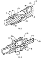
- FIG. 6 is a longitudinal section through a further embodiment of a stroke adjusting device
- FIG. 7 is a longitudinal section through a further embodiment of a stroke adjusting device
- FIG. 8 is a perspective sectional view showing a further embodiment of a stroke adjusting device
- FIG. 9 is a perspective sectional illustration showing a further embodiment of a stroke adjusting device.
- FIG. 10 is a perspective view of a further embodiment of a stroke adjusting device.
- a road paver 1 in FIG. 1 for laying down a pavement 6 of a bituminous or concrete-type paving material 5 on a subgrade 7 is equipped on a chassis 2 with a paving material hopper 4 and in a driver's cab with a control panel P of a controller, e.g. with a control system 25 .
- the control system 25 could also be arranged at a different place inside the road paver 1 or in a screed 3 towed by the road paver, namely in functional association with the controller or the control panel P or an external control panel P′ arranged on the screed 3 .
- the screed 3 is fastened to traction bars 8 that at both sides are connected to articulation points 9 of the road paver 1 .
- the articulation points 9 can be moved upwards and downwards via adjusting devices 10 , such as leveling cylinders, for instance in order to adjust the pavement thickness S of the laid-down pavement 6 .
- the screed 3 comprises, for instance, a base screed 11 and extension screeds 12 movable on said base screed, each with a compaction unit 13 comprising at least a tamper 14 and a tamper bar, respectively, and a sole plate 18 acting on the paving material 4 , wherein preferably the screed 3 floatingly operates at a small positive setting angle ⁇ relative to a plane in parallel with the subgrade 7 .
- the tamper bar 14 is cyclically drivable at work cycles for precompaction and carries out strokes H at a frequency F.
- the road paver 1 is running at a paving speed V on the subgrade 7 .
- the screed 3 (in the base screed 11 and each extension screed 12 ) additionally includes at least one eccentric vibrator (not shown) for acting on the sole plate 18 with vertical pulses, and optionally in work travel direction at the rear side at least one pressing bar of a high-performance compaction device (not shown).
- the eccentric vibrator and the high-performance compaction device are selective options of a screed 3 whereas the tamper 14 can pertain to the basic equipment.
- the paving speed V and also the pavement thickness S are paving parameters that are changing or can be changed optionally even during the ongoing paving work.
- the tamper 14 must produce a precompaction in the paving material 5 that has loosely been poured onto the subgrade 7 , and the precompaction should be kept at least predominantly constant independently of varying paving parameters.
- Further paving parameters that might be of relevance to precompaction may be type and consistency of the paving material 5 , the temperature thereof, ambient conditions, the design of the screed 3 , or the like.
- the precompaction is kept substantially constant, independently of the paving parameters varying during the ongoing paving work, in that at least the stroke H of the work cycles of the tamper 14 is adjusted in response to at least one paving parameter, optionally even automatically, expediently also the frequency F, namely via the control system 25 that receives or is aware of at least one paving parameter as a control variable, and on which preferably a desired precompaction degree is set as a setpoint or target value.
- the control system 25 can be operated with characteristic curves and/or a characteristic map. Each characteristic curve or the characteristic map is predetermined and stored. Expediently, the control system 25 is an automatic one and is computerized.
- FIG. 2 shows a diagram of the stroke H (or of the frequency F) over the pavement thickness S (or the paving speed V).
- the continuous characteristic curve H illustrates how the stroke H is here continuously increasing with an increasing pavement thickness S (or with an increasing paving speed V).
- the broken lines outline the measure known from the prior art, i.e. to change the stroke H in several steps, each with an interrupted paving operation, wherein the obliquely hatched fields X and Y illustrate that the stroke H changed according to the staircase profile, or the precompaction, is not matching over a considerable portion of the changes made in the pavement thickness S or the paving speed V.
- the continuous characteristic curve F illustrates the also possible change in the frequency with an increasing pavement thickness S or paving speed V.
- the characteristic curves H, F can be stored in a characteristic map executed by the control system 25 during the ongoing paving work.
- the characteristic curve F, H or the characteristic map is predetermined such that with respect to a high and constant final quality of the laid-down pavement 6 there is always an optimum ratio between the pavement thickness and/or the paving speed and at least the stroke H; expediently, the frequency F is also optimal.
- the stroke H and optionally also the frequency F are expediently adjusted either automatically and even during the ongoing paving work while changes in at least one paving parameter such as the pavement thickness S and/or the paving speed V are sensed, or in an operator-controlled manner.
- FIG. 3 illustrates an inner portion of the screed 3 with the tamper 14 .
- the tamper bar 14 is shielded on the front side of the screed 3 by a cover 19 (draw-in snout) and is substantially vertically movably guided between the cover 19 and the front edge of the sole plate 18 .
- a bearing block 16 is mounted having a relative height position that can e.g. be adjusted by means of an adjusting screw 20 in such a manner that the tamper bar 14 in the lower dead center of each work cycle occupies a specific relative position with respect to the sole plate 18 .
- an eccentric shaft 15 is rotatably supported and includes a respective eccentric section 22 with a specific eccentricity.
- the eccentric section 22 is located in a connecting rod 21 which connects the eccentric shaft 15 to the tamper bar 14 .
- an eccentric bushing 23 is coupled in a rotationally fixed manner with the eccentric section 22 , for instance in the illustrated embodiment via an adjusting mechanism 24 supported on the frame 17 , and is rotatably supported in the connecting rod 21 .
- the eccentric bushing 23 can be rotated relative to the eccentric section 22 of the eccentric shaft 15 and can be coupled again in a rotationally fixed manner with the eccentric shaft 15 in the respectively adjusted rotary position.
- the relative rotation of the eccentric bushing 23 relative to the eccentric section 22 effects an adjustment of the stroke which is transmitted by the connecting rod 21 to the tamper bar 14 .
- the stroke can be adjusted preferably automatically via the control system 25 which is in operative communication with the adjusting mechanism 24 , namely depending on changes in specific paving parameters.
- the adjusting mechanism 24 could also be controlled or actuated by an operator, if necessary.
- the illustration of the adjusting mechanism 24 in FIG. 3 is schematic because the adjusting mechanism 24 must of course act due to the rotational direction of the eccentric shaft 15 indirectly as a stroke adjusting device via the eccentric shaft 15 on the eccentric bushing 23 . This shall be explained in detail with reference to the further embodiment.
- the eccentric bushing 23 is rotatably seated on the eccentric section 22 of the eccentric shaft 15 .
- the shaft is e.g. hollow in such a way that an interior control rod 27 leads to an adjusting drive 26 located outside of the eccentric shaft 15 .
- the control rod 27 is coupled with a driver 28 which is adjustable in a groove 29 axially in the eccentric shaft 15 and is connected to said shaft in a rotationally fixed manner and which with an extension 30 projecting out of the groove 29 to the outside engages into a thread-like guide path 31 of the eccentric bushing 23 .
- the eccentric section 22 exhibits a first eccentricity relative to the rotational axis of the eccentric shaft 15 , but is cylindrical on the outer circumference.
- the cylindrical outer circumference of the eccentric bushing 23 is eccentric relative to the cylindrical inner circumference. Since the cylindrical outer circumference of the eccentric bushing 23 is rotatable in the connecting rod 21 , and since the tamper bar 14 is movable in a fixed vertical plane, the extent of the eccentricity resulting from the first and second eccentricities depends on which relative rotational position is set between the eccentric bushing 23 and the eccentric section 22 .
- the efficient eccentricity extent determines half the stroke H of a work cycle.
- the stroke H can be adjusted in a continuously variable manner between a minimum and a maximum.
- the eccentric bushing 23 always remains coupled with the eccentric shaft 15 in a rotationally fixed manner.
- the adjusted axial position of the driver 28 is e.g. maintained by the adjusting drive 26 .
- the eccentric shaft 15 is rotatably supported e.g. at the left end in FIG. 4 in a bearing block (which is here not shown) and is driven from the end at the right side in FIG. 4 via a hydromotor (not shown).
- the adjusting drive 26 can thus be arranged in front of the end at the left side in FIG. 4 in the screed or on the frame 17 .
- FIG. 5 mainly differs from FIG. 4 in that the adjusting mechanism 24 contains the driver 28 which is axially displaceable in the outwardly open groove 29 of the eccentric shaft 15 , in such a matter that the adjusting drive 26 is operative via the control rod 27 from the outside of the eccentric shaft 15 .
- the extension 30 of the driver 28 engages into the thread-like guide path 31 of the eccentric bushing 22 which, though it is seated in a relatively rotatable manner on the eccentric section 22 of the eccentric shaft 15 , remains coupled with the eccentric shaft 15 in a rotationally fixed manner via the driver 28 , the groove 29 and the extension 30 in each axial position of the driver 28 .
- the adjusting mechanism 24 shown in FIG. 6 comprises a rotary type step switching mechanism which is cyclically operated by the adjusting drive 26 , which is e.g. supported on the frame 17 of the screed, so as to rotate the eccentric bushing 23 relative to the eccentric section 22 of the eccentric shaft 15 .
- the eccentric bushing 23 is rotatably supported via at least one roller bearing 32 .
- at least one axial groove 29 is provided having arranged therein an adjusting mechanism 33 which is coupled with the eccentric shaft 15 to be axially movable, but rotationally fixed.
- a sawtooth gearing 34 (circumferential gearing) is provided, as well as a sawtooth gearing 35 that is circumferentially offset relative thereto and provided at the right end of the adjusting mechanism 33 .
- the eccentric bushing 23 has corresponding sawtooth gearings 37 and 36 , respectively, at both ends.
- the axial length of the eccentric bushing 23 between the sawtooth gearings 36 , 37 thereof is slightly shorter than the inner width between the sawtooth gearings 35 , 34 .
- the adjusting mechanism 33 is hydraulically axially adjustable through this width difference for instance by means of a ring piston 41 of the adjusting drive 26 (hydraulically actuatable ring chamber 40 ).
- the left-side end of the adjusting mechanism 33 is supported on a spring 39 of a stop 38 on the eccentric shaft 15 .
- the adjusting mechanism 33 For rotating the eccentric bushing 23 on the eccentric section 22 the adjusting mechanism 33 is moved by the ring piston 41 out of the position shown in FIG. 6 to the left side until the gearings 34 , 37 are disengaged and the gearings 35 , 36 are meshing with each other.
- the eccentric bushing 23 is thereby rotated by a pitch by way of a circumferential displacement between at least the gearings 34 and 35 .
- the pressure is thereafter reduced in the ring chamber 40 so that the spring 39 shifts the adjusting mechanism 33 back into the position shown in FIG. 6 , and e.g. the eccentric bushing 23 is further rotated by a further pitch and is thereafter again coupled in a rotationally fixed manner with the eccentric section 22 .
- the adjusting mechanism 24 comprises the ring piston 41 as the adjusting drive 26 .
- the adjusting drive 26 can be supported on the frame 17 of the screed.
- the ring piston 41 directly acts on an axial end of the eccentric bushing 23 , which bushing 23 is pressed by the spring 39 , which is supported on the stop 39 on the eccentric shaft 15 , via a stop ring 42 and a roller bearing 43 axially onto a conical section 22 ′ of the eccentric section 22 of the eccentric shaft 15 and coupled with the eccentric shaft 15 in a rotationally fixed manner.
- the eccentric bushing 23 can be moved to the left side against the force of the spring 39 by the ring piston 41 out of the position shown in FIG.
- the eccentric shaft 15 can be rotated in the roller bearing 43 relative to the eccentric bushing 23 until the ring piston 41 is retracted again and the eccentric bushing 23 is brought by the spring 39 into renewed frictional contact with the conical section 22 ′.
- the relative rotational movement could also be carried out on the eccentric bushing 23 .
- the connecting rod 21 follows these minor axial movements of the eccentric bushing 23 in the embodiment in FIG. 7 .
- the roller bearing 32 could have an axial play in the connecting rod 21 or on the eccentric bushing 23 .
- the eccentric bushing 23 could even be coupled through a gearing with the conical section 22 ′ in a rotationally fixed manner.
- the eccentric bushing 23 is not rotated relative to the eccentric section 22 of the eccentric shaft 15 , but it is shifted in a direction transverse to the axis of the eccentric shaft 15 so as to change the whole efficient eccentricity and thus the stroke.
- the eccentric bushing 23 can e.g. be configured with coaxial inner and outer cylindrical circumferences, i.e. in a circular cylindrical manner, and arranged in a rotationally fixed manner on two opposite guide blocks 44 that are shiftable in outwardly open grooves of the pierced eccentric shaft 15 in a direction transverse to the axis of the eccentric shaft 15 and are rotationally fixed with the eccentric shaft.
- Each guide block 44 is provided on the inside with an inclined guide surface 45 that is standing on an inclined guide ramp 47 of a control rod 46 which is axially displaceable in the eccentric shaft 15 by means of the adjusting drive 26 and fixable in the respectively selected adjusting position.
- the adjusting drive 36 can be configured hydraulically, electrically or mechanically.
- the eccentric bushing 23 is cylindrical (which is advantageous under technical manufacturing aspects), it exhibits an eccentric action relative to the eccentric section 22 .
- FIG. 9 which is functionally similar to the embodiment of FIG. 8 , two diametrically opposite axial grooves 29 are formed in the eccentric section 22 of the eccentric shaft 44 , the guide blocks 44 being coupled in said grooves with the eccentric shaft 15 in an axially movable and rotationally fixed manner.
- Each guide block 44 is engaged by a control rod 46 ′ which is or can be coupled with the adjusting drive 26 .
- the inclined guide surface 47 ′ is formed on the outside on the guide block 44 and engages into an axial groove on the inner surface of the eccentric bushing 23 .
- the inclined guide ramp 45 ′ is formed in said axial groove, so that the eccentric bushing is shifted, similar to the way shown in FIG. 8 , in a direction transverse to the axis of the eccentric shaft by the axial displacement of the guide blocks 44 and remains coupled in a rotationally fixed manner with the eccentric shaft 15 .
- the eccentric bushing 23 can be cylindrical.
- the adjusting mechanism 24 is integrated into a toggle mechanism via which the rotational movement of the eccentric shaft 15 with its eccentric section 22 is transmitted via a push rod 48 rotatably supported on the eccentric section 22 and via an articulation axis 49 to the connecting rod 21 on which the tamper bar 14 is secured.
- An end of an adjusting lever 50 is articulated to the connecting rod 21 , preferably on the same articulation axis 49 , the adjusting lever being supported with a pivot abutment 51 (e.g. a pin) in a guide path 52 of the bearing block 16 ′ of the eccentric shaft 15 .
- the bearing block 16 ′ can be mounted on the frame 17 of the screed.
- the guide path 52 is e.g.
- the adjusting drive 26 is operative between the bearing block 16 ′ and the pivot abutment 51 so as to adjust the pivot abutment 51 inside the guide path 52 . This changes the eccentricity sensed on the eccentric section 22 and transmitted by the adjusting lever 50 to the connecting rod 21 , or the stroke of the tamper bar 14 , respectively.
- the guide path 52 is configured and arranged relative to the axis of the eccentric shaft 15 and the articulation axis 49 such that independently of the adjusting position of the pivot abutment 51 in the guide path 52 the lower dead center of the work cycles of the tamper bar 14 remains stationary in relation to the sole plate 18 , i.e. in the stroke adjustment only the upper dead center shifts.
- the rotation of the eccentric shaft 15 reciprocates the push rod 48 substantially in parallel with the upper side of the frame 17 via the eccentric shaft 22 .
- Said swing movement effects a pivotal movement of the adjusting lever 50 about the pivot abutment 51 via the joint articulation axis 49 , said pivot movement describing a circular-arc section.
- the adjusting lever 50 derives therefrom a substantially vertical stroke component for the connecting rod 21 . The extent of this stroke component is changed by adjusting the pivot abutment 51 in the guide path 52 .
- the articulation points 9 of the traction bars 8 of the road paver 1 of FIG. 1 are adjustable in their height with the leveling cylinders 10 e.g. via actuators 10 ′ (hydraulic valves or the like) and influence the setting angle ⁇ of the screed 3 .
- the setting angle ⁇ should be positive, but have an optimal size, i.e. not too flat and not too steep and its optimal size is maintained by the control system 25 .
- Lifting cylinders 55 are additionally hinged to the chassis 2 , the lifting cylinders acting on the traction bars 8 and serving to position the screed 3 in a lifted position for instance for transportation travel, or to carry out a screed relief or optionally to intensify the support pressure of the screed 3 .
- the tamper 14 of the compaction unit 13 is (see FIG. 3 ) for instance operable by means of an eccentric drive with selectable stroke H and selectable frequency F.
- a speed selector 26 is provided for setting the paving speed V.
- the speed selector 53 can be adjusted via an actuator (not shown) and optionally by the control system 25 so as to vary the paving speed V.
- the paving speed V is sensed by a symbolically illustrated sensor 41 and transmitted to the control system 25 .
- the sensor 59 can be placed in the road paver e.g. in the control panel P or in a travel drive or it may sense a reference on the subgrade 7 .
- an input section 54 may be provided for the input of parameters and/or for the display of parameters.
- the lifting cylinders 28 have assigned thereto at least one actuator 56 , e.g. a magnetically operated hydraulic valve.
- At least one sensor 58 may be provided as equipment for the road paver 1 , the sensor sensing the temperature, density or consistency of the paving material, e.g. directly in front of the screed 3 , and transmitting these values as information to the control system 25 , if necessary.
- This sensed information could also be input by an operator.
- the screed 3 has disposed thereon at least one sensor 57 that senses the setting angle ⁇ of the screed relative to the subgrade 7 .
- Sensor 57 could also sense the setting angle ⁇ on the traction arms 8 .
- a plurality of sensors 57 can be provided across the pave width.
- a sensor 60 can be provided for sensing the pavement thickness S, the sensor sensing for instance the subgrade 7 or a reference (not shown) on the subgrade 7 .
- actuators are provided for setting the tamper stroke H or the tamper frequency F, respectively, and can be prompted by control signals generated by means of the control system 25 to implement control signals.
- FIG. 3 shows the mechanism 24 forming an actuator for the tamper stroke H for rotating the eccentric bushing 23 relative to the eccentric section 22 .
- the adjustment of the tamper stroke H, which is each time matched to the pave parameters, is carried out automatically via the control system 25 .
- the eccentric shaft 15 is rotationally driven for instance by a hydromotor 32 .
- the speed thereof defines the tamper frequency F.
- a magnetically operated valve may serve as an actuator 33 for the hydromotor 3 , i.e. a proportional current-regulating valve that can be actuated by the control system 25 with control signals.
- control system 25 a plurality of different machine or site or paving-material parameters are automatically controlled depending on one another so as to minimize, for instance, error rates in the laid pavement 6 and to enhance the quality of the laid pavement 6 .
- the tamper 14 has compacted the loosely pre-laid paving material 5 to such a degree that a bearing capacity is created that is adequate for the screed 3 . It is only then that it is ensured that the screed 3 with its sole plate 18 is floatingly towed at an advantageous setting angle ⁇ .
- the tamper stroke H, the tamper frequency F, the paving speed V and the setting angle ⁇ depend on one another to a great degree. For instance, if the paving speed V is reduced, this will have an effect on the precompaction of the paving material at a constant tamper frequency and leveling cylinder adjustment.
- the bearing capacity of the paving material is increasing, so that the screed 3 is further floating and the setting angle ⁇ is decreasing.
- control variables for at least the compaction unit 13 and the tamper 14 are automatically controlled and regulated according to the invention by the control system 25 depending on the relevant processes or machine parameters. To be more specific, a uniform and optimal compaction of the paving material over the whole pave width of the screed is thereby achieved as a contribution to quality assurance.
- the setting angle ⁇ is sensed by means of the sensor 57 or a plurality of sensors 57 distributed in transverse direction and is transmitted to the control system 25 or a controller specifically in charge of this pave parameter so as to adapt the tamper stroke H upon change in the setting angle ⁇ , so that the setting angle ⁇ is returned again to an optimal value or cannot change significantly, thereby achieving the desired pavement thickness S with a permanently optimal pre-compaction.
- the setting angle ⁇ may vary over the transverse paving width of the screed 3 .
- the control system 25 can then adapt the tamper stroke H for each tamper 14 individually in a corresponding way, so that despite a pavement thickness S varying in a direction transverse to the pave travel direction the compaction remains uniform over the pave width.
- the tamper frequency F can be adapted in a particularly simple way in that upon change in the tamper stroke H the tamper frequency F is adapted automatically in conformity with a characteristic curve or in a characteristic map that is entered into or exists in the control system.
- a relevant paving parameter is e.g. also the density or consistency of the paving material 5 .
- the road paver 1 is equipped with a sensor 58 , as mentioned, by means of which the density or consistency of the paving material can be sensed, the sensed value is compared with a target value and in case of a deviation from the target value an adaptation e.g. of the tamper stroke H and/or the tamper frequency F and/or the leveling cylinder setting is carried out via the control system 25 in such a way that upon deviation of the sensed density or consistency the setting angle is substantially maintained and the same compaction and evenness and thus quality of the pavement 6 is achieved.
- the paving speed V is also an important paving parameter because in case of a change in paving speed an adaptation of the tamper stroke H and/or the tamper frequency F and/or the leveling cylinder setting, e.g. via the automatic control system 25 , is needed.
- a further relevant paving parameter is the stiffness of the paving material 5 and/or the temperature thereof.
- These paving parameters can e.g. be sensed individually or in combination by means of the sensor 58 or a stiffness and a temperature sensor and transmitted to the control system 25 , or after detection they can be entered by an operator on section 54 , whereupon the control system, if recommended by the sensed values, adapts the tamper stroke H and/or the tamper frequency F and/or the leveling cylinder setting accordingly.
- it is also possible to carry out an adjustment on the lifting cylinders 55 e.g.
Landscapes
- Engineering & Computer Science (AREA)
- Architecture (AREA)
- Civil Engineering (AREA)
- Structural Engineering (AREA)
- Mining & Mineral Resources (AREA)
- Mechanical Engineering (AREA)
- Road Paving Machines (AREA)
Priority Applications (1)
| Application Number | Priority Date | Filing Date | Title |
|---|---|---|---|
| US14/542,326 US9790648B2 (en) | 2009-11-20 | 2014-11-14 | Method for laying down a pavement, a screed and a road paver |
Applications Claiming Priority (6)
| Application Number | Priority Date | Filing Date | Title |
|---|---|---|---|
| EP09014516 | 2009-11-20 | ||
| EP090145160.0 | 2009-11-20 | ||
| EP090145160 | 2009-11-20 | ||
| EP10002895 | 2010-03-18 | ||
| EP10002895.0A EP2325392B1 (de) | 2009-11-20 | 2010-03-18 | Verfahren zum einbauen eines belages, einbaubohle und strassenfertiger |
| EP10002895.0 | 2010-03-18 |
Related Child Applications (1)
| Application Number | Title | Priority Date | Filing Date |
|---|---|---|---|
| US14/542,326 Division US9790648B2 (en) | 2009-11-20 | 2014-11-14 | Method for laying down a pavement, a screed and a road paver |
Publications (2)
| Publication Number | Publication Date |
|---|---|
| US20110123267A1 US20110123267A1 (en) | 2011-05-26 |
| US8998530B2 true US8998530B2 (en) | 2015-04-07 |
Family
ID=42111282
Family Applications (2)
| Application Number | Title | Priority Date | Filing Date |
|---|---|---|---|
| US12/949,889 Active 2031-10-14 US8998530B2 (en) | 2009-11-20 | 2010-11-19 | Method for laying down a pavement, a screed and a road paver |
| US14/542,326 Active 2031-09-04 US9790648B2 (en) | 2009-11-20 | 2014-11-14 | Method for laying down a pavement, a screed and a road paver |
Family Applications After (1)
| Application Number | Title | Priority Date | Filing Date |
|---|---|---|---|
| US14/542,326 Active 2031-09-04 US9790648B2 (en) | 2009-11-20 | 2014-11-14 | Method for laying down a pavement, a screed and a road paver |
Country Status (5)
| Country | Link |
|---|---|
| US (2) | US8998530B2 (de) |
| EP (3) | EP3138961B1 (de) |
| JP (1) | JP5785382B2 (de) |
| CN (1) | CN102071635B (de) |
| PL (3) | PL3375936T3 (de) |
Cited By (10)
| Publication number | Priority date | Publication date | Assignee | Title |
|---|---|---|---|---|
| US20150139729A1 (en) * | 2013-11-19 | 2015-05-21 | Caterpillar Paving Products Inc. | Paving machine with automatically adjustable screed assembly |
| US9487924B2 (en) | 2014-02-07 | 2016-11-08 | Joseph Voegele Ag | Tamper |
| US9995008B2 (en) | 2016-09-15 | 2018-06-12 | Caterpillar Paving Products Inc. | System and method for controlling vibratory effort on asphalt mat |
| US10060086B2 (en) * | 2015-12-23 | 2018-08-28 | Bomag Gmbh | Tamping beam device of a paving screed, paving screed, road paver, and method for changing the stroke of a tamping beam device |
| US10166573B2 (en) * | 2015-12-28 | 2019-01-01 | Volvo Construction Equipment Ab | Eccentric assembly for a vibration compacting machine |
| US10280572B1 (en) | 2017-11-07 | 2019-05-07 | Caterpillar Paving Products Inc. | System for heating a paving screed |
| US10316476B2 (en) | 2016-04-11 | 2019-06-11 | Caterpillar Paving Products Inc. | Screed assembly for a paving machine |
| US10422086B2 (en) | 2017-11-13 | 2019-09-24 | Caterpillar Paving Products Inc. | Screed control system |
| US20210269993A1 (en) * | 2020-02-27 | 2021-09-02 | Joseph Voegele Ag | Road paver with a projector |
| US11255057B2 (en) | 2020-03-07 | 2022-02-22 | Brian Gallagher | Screed assembly for road paving machines, and a method for repaving road surfaces |
Families Citing this family (40)
| Publication number | Priority date | Publication date | Assignee | Title |
|---|---|---|---|---|
| PL2366831T3 (pl) * | 2010-03-18 | 2015-07-31 | Joseph Voegele Ag | Sposób sterowania procesem przy wbudowywaniu nawierzchni i wykańczarka |
| EP2366832B1 (de) * | 2010-03-18 | 2015-09-23 | Joseph Vögele AG | Verfahren und Strassenfertiger zum Einbauen einer verdichteten Deckenschicht |
| PL2535456T3 (pl) * | 2011-06-15 | 2014-05-30 | Joseph Voegele Ag | Wykańczarka z urządzeniem do pomiaru grubości warstwy |
| CN102330404B (zh) * | 2011-07-14 | 2013-04-17 | 中联重科股份有限公司 | 摊铺机以及控制摊铺机的方法、装置和系统 |
| EP2578748B1 (de) * | 2011-10-04 | 2018-08-29 | Joseph Vögele AG | Außensteuerstand für eine Baumaschine |
| DE102011119937A1 (de) | 2011-12-01 | 2013-06-06 | Bomag Gmbh | Verfahren und Vorrichtung zur Amplitudenverstellung einer Stampfleiste eines Straßenfertigers |
| DE102011119938A1 (de) * | 2011-12-01 | 2013-06-06 | Bomag Gmbh | Verfahren und Vorrichtung zur Hubverstellung einer Stampfleiste eines Straßenfertigers |
| EP2599920B1 (de) * | 2011-12-01 | 2015-02-11 | Joseph Vögele AG | Straßenfertiger |
| US8371770B1 (en) | 2012-04-09 | 2013-02-12 | Caterpillar Inc. | Apparatus for tamping paving material |
| CN102808369B (zh) * | 2012-05-29 | 2015-07-08 | 三一重工股份有限公司 | 熨平板压实梁、熨平板和摊铺机 |
| US8979425B2 (en) | 2012-10-30 | 2015-03-17 | Caterpillar Paving Products Inc. | Screed extender speed control |
| PL2789740T3 (pl) * | 2013-04-12 | 2018-05-30 | Joseph Vögele AG | Pomiar temperatury podłoża za pomocą wykańczarki |
| PL3075909T3 (pl) * | 2015-03-30 | 2018-02-28 | Joseph Vögele AG | Maszyna do budowy dróg z siecią do transmisji danych i zastosowanie części przewodu prądowego |
| US9587361B2 (en) | 2015-04-08 | 2017-03-07 | Caterpillar Paving Products Inc. | Temperature dependent auto adaptive compaction |
| CN106835903B (zh) * | 2017-01-16 | 2023-01-20 | 特路(北京)科技有限公司 | 摊铺机及铺路系统 |
| CN107217574A (zh) * | 2017-06-27 | 2017-09-29 | 徐州迈斯特机械科技有限公司 | 一种沥青摊铺机 |
| US10669678B2 (en) * | 2017-12-14 | 2020-06-02 | Caterpillar Paving Products Inc. | System and method for generating a paving material map |
| EP3564440B1 (de) * | 2018-05-04 | 2022-03-23 | Joseph Vögele AG | Einbauzug |
| US10480132B1 (en) * | 2018-08-01 | 2019-11-19 | Caterpillar Paving Products Inc. | Fixed screed power take-off for improved performance |
| US10889944B2 (en) * | 2018-08-28 | 2021-01-12 | Caterpillar Paving Products Inc. | Control system for controlling operation of compaction systems of a paving machine |
| CN109610278B (zh) * | 2019-01-29 | 2021-01-26 | 长安大学 | 一种沥青混合料高密实摊铺成型方法 |
| CN109958037A (zh) * | 2019-04-03 | 2019-07-02 | 任新庄 | 一种易于调节的道路沥青铺设装置 |
| CN110565486A (zh) * | 2019-09-25 | 2019-12-13 | 三一汽车制造有限公司 | 摊铺机找平显示系统、摊铺机及控制方法 |
| PL3851584T3 (pl) * | 2020-01-16 | 2023-03-20 | Joseph Vögele AG | Wykańczarka ze sterowaniem zagęszczenia |
| US12416121B2 (en) | 2020-01-27 | 2025-09-16 | Volvo Construction Equipment Ab | Tamper device for a screed of a working machine and a method for adjusting a stroke of a tamper device for a screed of a working machine |
| EP3960933A1 (de) * | 2020-08-27 | 2022-03-02 | Joseph Vögele AG | Verfahren zum einstellen einer temperatur eines glättblechs einer einbaubohle eines strassenfertigers |
| CN112626976A (zh) * | 2020-12-08 | 2021-04-09 | 广东龙越建筑工程有限公司 | 一种弧形路面刮平收光器 |
| PL4029992T3 (pl) | 2021-01-14 | 2023-09-11 | Joseph Vögele AG | Wykańczarka i sposób przestawiania skoku ubijaka |
| EP4029991B1 (de) | 2021-01-14 | 2023-05-10 | Joseph Vögele AG | Tamperhubverstellung |
| US11572662B2 (en) | 2021-04-01 | 2023-02-07 | Caterpillar Paving Products Inc. | Tow point index |
| CN113585005B (zh) * | 2021-08-13 | 2022-09-23 | 陈小雨 | 沥青路面铺设用引导装置 |
| CN114250675B (zh) * | 2022-02-11 | 2022-07-22 | 湖南长株高速公路开发有限责任公司 | 高速公路互通匝道路基加宽填筑固化土施工方法 |
| CN114934425B (zh) * | 2022-05-25 | 2024-04-19 | 中国铁建股份有限公司 | 一种基于道面板的路面铺设方法 |
| EP4368777B1 (de) * | 2022-11-08 | 2025-05-07 | Ammann Schweiz AG | Vibrationsantriebsstrang zur herstellung eines estrichkörpers einer estrichvorrichtung eines pflasterers, estrichkörper, estrichvorrichtung und pflasterer |
| EP4371832A1 (de) * | 2022-11-18 | 2024-05-22 | Volvo Truck Corporation | Fahrzeugalarm basierend auf einem erkannten betriebsrisiko |
| EP4428303B1 (de) | 2023-03-08 | 2025-01-15 | Joseph Vögele AG | Verfahren und strassenbausystem zum dynamischen steuern einer einbaugeschwindigkeit eines strassenfertigers |
| EP4450707A1 (de) * | 2023-04-18 | 2024-10-23 | Joseph Vögele AG | Einbaubohlenanordnung mit funktioneller kopplung zwischen einer höhenverstelleinrichtung und einer kippeinrichtung |
| US20250043520A1 (en) * | 2023-08-04 | 2025-02-06 | Wirtgen Gmbh | Constant surface patterns during slip form paving |
| WO2025030191A1 (de) | 2023-08-09 | 2025-02-13 | Woehrer Stefan | Vorrichtung zum herstellen einer betonfahrbahn |
| CN119715052B (zh) * | 2024-11-26 | 2026-01-30 | 中国华冶科工集团有限公司 | 铺平辅助装置 |
Citations (21)
| Publication number | Priority date | Publication date | Assignee | Title |
|---|---|---|---|---|
| US1898158A (en) * | 1929-09-24 | 1933-02-21 | Winkler Kaspar | Mechanical pavior |
| US3508475A (en) * | 1967-08-30 | 1970-04-28 | Barber Greene Co | Plate towed compactor |
| US3545349A (en) * | 1968-08-01 | 1970-12-08 | Hans Gert Otterman | Self-propelling paving machine |
| GB2091792A (en) | 1980-12-16 | 1982-08-04 | Phoenix Tagpag | An asphalt laying machine |
| DE3127377A1 (de) | 1981-07-09 | 1983-01-27 | LIBA Lingener Baumaschinen Gesellschaft mbH & Co. KG, 4450 Lingen | Verdichtungsbohle fuer strassenfertiger |
| US4493585A (en) | 1981-04-07 | 1985-01-15 | Joseph Vogele Ag | Bituminous finisher |
| US4507014A (en) * | 1983-01-04 | 1985-03-26 | Abg-Werke Gmbh | Consolidating plank for a highway finishing machine |
| US4828428A (en) * | 1987-10-23 | 1989-05-09 | Pav-Saver Manufacturing Company | Double tamping bar vibratory screed |
| EP0374428A1 (de) | 1988-12-19 | 1990-06-27 | Dynapac Gmbh | Verdichtungsbohle für einen Strassenfertiger |
| JPH03150927A (ja) | 1989-11-07 | 1991-06-27 | Kokusai Electric Co Ltd | 音声通信装置 |
| US5401115A (en) * | 1993-03-10 | 1995-03-28 | Cedarapids, Inc. | Paver with material supply and mat grade and slope quality control apparatus and method |
| WO2000070150A1 (en) | 1999-05-19 | 2000-11-23 | Ingersoll-Rand Company | Temperature sensing for controlling paving and compaction operations |
| US6238135B1 (en) * | 1998-08-11 | 2001-05-29 | Abg Allgemeine Baumaschinengesellschaft Mbh | Paver having adjustable screed angle using a tamper bar |
| JP2002021016A (ja) | 2000-07-03 | 2002-01-23 | Sumitomo (Shi) Construction Machinery Manufacturing Co Ltd | 舗装機械の締め固め制御装置 |
| US20020141823A1 (en) * | 2001-03-29 | 2002-10-03 | Blaw-Konx Construction Equipment Corporation | Apparatus for tamping paving material |
| US20020168226A1 (en) * | 2001-05-14 | 2002-11-14 | Feucht Timothy A. | Automatic tamping mechanism control |
| JP2003129413A (ja) | 2001-10-25 | 2003-05-08 | Nippon Hodo Co Ltd | 複数層同時舗装における敷均厚さ制御方法及びその装置 |
| EP1310598A2 (de) | 2001-11-13 | 2003-05-14 | ABG Allgemeine Baumaschinen-Gesellschaft mbH | Fertiger zum bodenseitigen Einbau von Schichten für Strassen od. dgl. |
| EP1905899A2 (de) | 2006-09-28 | 2008-04-02 | Dynapac GmbH | Einbaubohle für einen Strassenfertiger |
| JP2008106514A (ja) | 2006-10-25 | 2008-05-08 | Sumitomo (Shi) Construction Machinery Manufacturing Co Ltd | 施工厚さ対応機能付道路舗装機械 |
| US7540686B2 (en) * | 2004-08-11 | 2009-06-02 | Abg Allgemeine Baumaschinen-Gesellschaft Mbh | Vibratory paving screed for a paver |
Family Cites Families (8)
| Publication number | Priority date | Publication date | Assignee | Title |
|---|---|---|---|---|
| JPH073042B2 (ja) * | 1990-11-08 | 1995-01-18 | 株式会社新潟鐵工所 | 敷均し機械におけるスクリードの初期設定方法 |
| DE4040029C1 (de) | 1990-12-14 | 1992-04-23 | Joseph Voegele Ag, 6800 Mannheim, De | |
| JP3150927B2 (ja) | 1997-08-22 | 2001-03-26 | 日本コンクリート工業株式会社 | 鉄筋コンクリート柱 |
| DE10038943A1 (de) * | 2000-08-09 | 2002-02-21 | Joseph Voegele Ag | Strassenfertiger und Einbauverfahren |
| JP5008599B2 (ja) * | 2008-04-14 | 2012-08-22 | 株式会社Nippo | 舗装体端部締固め装置 |
| JP3150927U (ja) * | 2009-03-19 | 2009-06-04 | 木村 貢 | アスファルトフィニッシャーのタンパ装置 |
| EP2325391B1 (de) * | 2009-11-20 | 2013-03-20 | Joseph Vögele AG | Tamper mit wählbarem Hub |
| PL2905378T3 (pl) * | 2014-02-07 | 2017-05-31 | Joseph Vögele AG | Ubijakowe urządzenie belkowe |
-
2010
- 2010-03-18 EP EP16189023.1A patent/EP3138961B1/de active Active
- 2010-03-18 PL PL18169491T patent/PL3375936T3/pl unknown
- 2010-03-18 EP EP18169491.0A patent/EP3375936B1/de active Active
- 2010-03-18 PL PL16189023T patent/PL3138961T3/pl unknown
- 2010-03-18 PL PL10002895T patent/PL2325392T3/pl unknown
- 2010-03-18 EP EP10002895.0A patent/EP2325392B1/de active Active
- 2010-11-15 JP JP2010254617A patent/JP5785382B2/ja active Active
- 2010-11-19 US US12/949,889 patent/US8998530B2/en active Active
- 2010-11-22 CN CN201010552930XA patent/CN102071635B/zh active Active
-
2014
- 2014-11-14 US US14/542,326 patent/US9790648B2/en active Active
Patent Citations (25)
| Publication number | Priority date | Publication date | Assignee | Title |
|---|---|---|---|---|
| US1898158A (en) * | 1929-09-24 | 1933-02-21 | Winkler Kaspar | Mechanical pavior |
| US3508475A (en) * | 1967-08-30 | 1970-04-28 | Barber Greene Co | Plate towed compactor |
| US3545349A (en) * | 1968-08-01 | 1970-12-08 | Hans Gert Otterman | Self-propelling paving machine |
| GB2091792A (en) | 1980-12-16 | 1982-08-04 | Phoenix Tagpag | An asphalt laying machine |
| US4502813A (en) * | 1980-12-16 | 1985-03-05 | A/S Phonix, Tagpap Og Vejmaterialer | Asphalt laying machine |
| US4493585A (en) | 1981-04-07 | 1985-01-15 | Joseph Vogele Ag | Bituminous finisher |
| DE3127377A1 (de) | 1981-07-09 | 1983-01-27 | LIBA Lingener Baumaschinen Gesellschaft mbH & Co. KG, 4450 Lingen | Verdichtungsbohle fuer strassenfertiger |
| US4507014A (en) * | 1983-01-04 | 1985-03-26 | Abg-Werke Gmbh | Consolidating plank for a highway finishing machine |
| US4828428A (en) * | 1987-10-23 | 1989-05-09 | Pav-Saver Manufacturing Company | Double tamping bar vibratory screed |
| EP0374428A1 (de) | 1988-12-19 | 1990-06-27 | Dynapac Gmbh | Verdichtungsbohle für einen Strassenfertiger |
| US5165820A (en) | 1988-12-19 | 1992-11-24 | Dynapac Gmbh | Compaction plank for a road finishing machine |
| JPH03150927A (ja) | 1989-11-07 | 1991-06-27 | Kokusai Electric Co Ltd | 音声通信装置 |
| US5401115A (en) * | 1993-03-10 | 1995-03-28 | Cedarapids, Inc. | Paver with material supply and mat grade and slope quality control apparatus and method |
| US6238135B1 (en) * | 1998-08-11 | 2001-05-29 | Abg Allgemeine Baumaschinengesellschaft Mbh | Paver having adjustable screed angle using a tamper bar |
| WO2000070150A1 (en) | 1999-05-19 | 2000-11-23 | Ingersoll-Rand Company | Temperature sensing for controlling paving and compaction operations |
| JP2002021016A (ja) | 2000-07-03 | 2002-01-23 | Sumitomo (Shi) Construction Machinery Manufacturing Co Ltd | 舗装機械の締め固め制御装置 |
| US20020141823A1 (en) * | 2001-03-29 | 2002-10-03 | Blaw-Konx Construction Equipment Corporation | Apparatus for tamping paving material |
| US6551018B2 (en) * | 2001-03-29 | 2003-04-22 | Blaw-Knox Construction Equipment Corporation | Apparatus for tamping paving material |
| US20020168226A1 (en) * | 2001-05-14 | 2002-11-14 | Feucht Timothy A. | Automatic tamping mechanism control |
| JP2003129413A (ja) | 2001-10-25 | 2003-05-08 | Nippon Hodo Co Ltd | 複数層同時舗装における敷均厚さ制御方法及びその装置 |
| EP1310598A2 (de) | 2001-11-13 | 2003-05-14 | ABG Allgemeine Baumaschinen-Gesellschaft mbH | Fertiger zum bodenseitigen Einbau von Schichten für Strassen od. dgl. |
| US6932538B2 (en) | 2001-11-13 | 2005-08-23 | Abg Allgemeine Baumaschinen-Gesellschaft Mbh | Paver for the paving of ground courses for roads or the like |
| US7540686B2 (en) * | 2004-08-11 | 2009-06-02 | Abg Allgemeine Baumaschinen-Gesellschaft Mbh | Vibratory paving screed for a paver |
| EP1905899A2 (de) | 2006-09-28 | 2008-04-02 | Dynapac GmbH | Einbaubohle für einen Strassenfertiger |
| JP2008106514A (ja) | 2006-10-25 | 2008-05-08 | Sumitomo (Shi) Construction Machinery Manufacturing Co Ltd | 施工厚さ対応機能付道路舗装機械 |
Cited By (13)
| Publication number | Priority date | Publication date | Assignee | Title |
|---|---|---|---|---|
| US9200415B2 (en) * | 2013-11-19 | 2015-12-01 | Caterpillar Paving Products Inc. | Paving machine with automatically adjustable screed assembly |
| US20150139729A1 (en) * | 2013-11-19 | 2015-05-21 | Caterpillar Paving Products Inc. | Paving machine with automatically adjustable screed assembly |
| US9487924B2 (en) | 2014-02-07 | 2016-11-08 | Joseph Voegele Ag | Tamper |
| US10060086B2 (en) * | 2015-12-23 | 2018-08-28 | Bomag Gmbh | Tamping beam device of a paving screed, paving screed, road paver, and method for changing the stroke of a tamping beam device |
| US10166573B2 (en) * | 2015-12-28 | 2019-01-01 | Volvo Construction Equipment Ab | Eccentric assembly for a vibration compacting machine |
| US10316476B2 (en) | 2016-04-11 | 2019-06-11 | Caterpillar Paving Products Inc. | Screed assembly for a paving machine |
| US9995008B2 (en) | 2016-09-15 | 2018-06-12 | Caterpillar Paving Products Inc. | System and method for controlling vibratory effort on asphalt mat |
| US10280572B1 (en) | 2017-11-07 | 2019-05-07 | Caterpillar Paving Products Inc. | System for heating a paving screed |
| US10550528B2 (en) | 2017-11-07 | 2020-02-04 | Caterpillar Paving Products Inc. | System for heating a paving screed |
| US10422086B2 (en) | 2017-11-13 | 2019-09-24 | Caterpillar Paving Products Inc. | Screed control system |
| US10550529B2 (en) | 2017-11-13 | 2020-02-04 | Caterpillar Paving Products Inc. | Screed control system |
| US20210269993A1 (en) * | 2020-02-27 | 2021-09-02 | Joseph Voegele Ag | Road paver with a projector |
| US11255057B2 (en) | 2020-03-07 | 2022-02-22 | Brian Gallagher | Screed assembly for road paving machines, and a method for repaving road surfaces |
Also Published As
| Publication number | Publication date |
|---|---|
| EP2325392A2 (de) | 2011-05-25 |
| EP3375936B1 (de) | 2021-08-11 |
| EP2325392A3 (de) | 2014-10-15 |
| PL3375936T3 (pl) | 2022-01-10 |
| EP2325392B1 (de) | 2020-09-30 |
| EP3375936A1 (de) | 2018-09-19 |
| EP3138961B1 (de) | 2018-08-22 |
| US20110123267A1 (en) | 2011-05-26 |
| PL2325392T3 (pl) | 2021-05-31 |
| EP3138961A1 (de) | 2017-03-08 |
| US9790648B2 (en) | 2017-10-17 |
| US20150139730A1 (en) | 2015-05-21 |
| CN102071635B (zh) | 2013-04-03 |
| CN102071635A (zh) | 2011-05-25 |
| JP5785382B2 (ja) | 2015-09-30 |
| JP2011106261A (ja) | 2011-06-02 |
| PL3138961T3 (pl) | 2019-03-29 |
Similar Documents
| Publication | Publication Date | Title |
|---|---|---|
| US8998530B2 (en) | Method for laying down a pavement, a screed and a road paver | |
| JP5345645B2 (ja) | 締固め仕上げ層を敷設するための方法及び路面仕上げ機 | |
| JP5820133B2 (ja) | 舗装道路製造の際の処理の制御方法及び道路仕上げ機 | |
| US6238135B1 (en) | Paver having adjustable screed angle using a tamper bar | |
| JP5255620B2 (ja) | 道路仕上げ機のスクリードのタンパ | |
| US9045871B2 (en) | Paving machine with operator directed saving and recall of machine operating parameters | |
| US6183160B1 (en) | Screeding apparatus and method incorporating oscillating attachment | |
| US20190376242A1 (en) | Screed control system | |
| EP2325393A1 (de) | Verfahren und Strassenfertiger zur Herstellung eines Strassenbelags | |
| US6773203B2 (en) | Paving machine and method for forming a concrete path | |
| CA3018491A1 (en) | System for disabling milling drum of milling machine | |
| DE102017202461A1 (de) | Stampfsysteme mit stufenlos einstellbarer amplitude und frequenz | |
| CN115506207A (zh) | 自动调零整平板组件 | |
| US5388927A (en) | Raiseable pan drag apparatus | |
| CN2514032Y (zh) | 一种双进料口拖式路面材料摊铺机 | |
| CN113152222A (zh) | 一种适用于小型摊铺机的熨平板 |
Legal Events
| Date | Code | Title | Description |
|---|---|---|---|
| AS | Assignment |
Owner name: JOSEPH VOGELE AG, GERMANY Free format text: ASSIGNMENT OF ASSIGNORS INTEREST;ASSIGNORS:BUSCHMANN, MARTIN;ZEGOWITZ, GUNTER;EUL, ACHIM;AND OTHERS;SIGNING DATES FROM 20101206 TO 20101208;REEL/FRAME:025541/0534 |
|
| STCF | Information on status: patent grant |
Free format text: PATENTED CASE |
|
| MAFP | Maintenance fee payment |
Free format text: PAYMENT OF MAINTENANCE FEE, 4TH YEAR, LARGE ENTITY (ORIGINAL EVENT CODE: M1551); ENTITY STATUS OF PATENT OWNER: LARGE ENTITY Year of fee payment: 4 |
|
| MAFP | Maintenance fee payment |
Free format text: PAYMENT OF MAINTENANCE FEE, 8TH YEAR, LARGE ENTITY (ORIGINAL EVENT CODE: M1552); ENTITY STATUS OF PATENT OWNER: LARGE ENTITY Year of fee payment: 8 |