US8937726B2 - Rotary position measuring instrument - Google Patents
Rotary position measuring instrument Download PDFInfo
- Publication number
- US8937726B2 US8937726B2 US13/603,846 US201213603846A US8937726B2 US 8937726 B2 US8937726 B2 US 8937726B2 US 201213603846 A US201213603846 A US 201213603846A US 8937726 B2 US8937726 B2 US 8937726B2
- Authority
- US
- United States
- Prior art keywords
- distance
- light source
- detector assembly
- measuring instrument
- rotary position
- Prior art date
- Legal status (The legal status is an assumption and is not a legal conclusion. Google has not performed a legal analysis and makes no representation as to the accuracy of the status listed.)
- Active, expires
Links
- 230000003287 optical effect Effects 0.000 claims abstract description 51
- 230000001419 dependent effect Effects 0.000 claims abstract description 8
- 230000005693 optoelectronics Effects 0.000 claims abstract description 7
- 239000000758 substrate Substances 0.000 claims description 4
- 230000000644 propagated effect Effects 0.000 claims description 3
- 238000001514 detection method Methods 0.000 description 9
- 230000008901 benefit Effects 0.000 description 5
- 230000000694 effects Effects 0.000 description 3
- 230000033001 locomotion Effects 0.000 description 3
- 238000000151 deposition Methods 0.000 description 2
- 238000004519 manufacturing process Methods 0.000 description 2
- 229910052751 metal Inorganic materials 0.000 description 2
- 239000002184 metal Substances 0.000 description 2
- 229920003023 plastic Polymers 0.000 description 2
- 238000002310 reflectometry Methods 0.000 description 2
- 230000002745 absorbent Effects 0.000 description 1
- 239000002250 absorbent Substances 0.000 description 1
- 229910052782 aluminium Inorganic materials 0.000 description 1
- XAGFODPZIPBFFR-UHFFFAOYSA-N aluminium Chemical compound [Al] XAGFODPZIPBFFR-UHFFFAOYSA-N 0.000 description 1
- 238000006073 displacement reaction Methods 0.000 description 1
- 239000011521 glass Substances 0.000 description 1
- PCHJSUWPFVWCPO-UHFFFAOYSA-N gold Chemical compound [Au] PCHJSUWPFVWCPO-UHFFFAOYSA-N 0.000 description 1
- 229910052737 gold Inorganic materials 0.000 description 1
- 239000010931 gold Substances 0.000 description 1
- 238000003384 imaging method Methods 0.000 description 1
- 239000000463 material Substances 0.000 description 1
- 238000000034 method Methods 0.000 description 1
- 238000012986 modification Methods 0.000 description 1
- 230000004048 modification Effects 0.000 description 1
- 239000004033 plastic Substances 0.000 description 1
- 230000035945 sensitivity Effects 0.000 description 1
- 230000007704 transition Effects 0.000 description 1
Images


Classifications
-
- G—PHYSICS
- G01—MEASURING; TESTING
- G01D—MEASURING NOT SPECIALLY ADAPTED FOR A SPECIFIC VARIABLE; ARRANGEMENTS FOR MEASURING TWO OR MORE VARIABLES NOT COVERED IN A SINGLE OTHER SUBCLASS; TARIFF METERING APPARATUS; MEASURING OR TESTING NOT OTHERWISE PROVIDED FOR
- G01D5/00—Mechanical means for transferring the output of a sensing member; Means for converting the output of a sensing member to another variable where the form or nature of the sensing member does not constrain the means for converting; Transducers not specially adapted for a specific variable
- G01D5/26—Mechanical means for transferring the output of a sensing member; Means for converting the output of a sensing member to another variable where the form or nature of the sensing member does not constrain the means for converting; Transducers not specially adapted for a specific variable characterised by optical transfer means, i.e. using infrared, visible, or ultraviolet light
- G01D5/32—Mechanical means for transferring the output of a sensing member; Means for converting the output of a sensing member to another variable where the form or nature of the sensing member does not constrain the means for converting; Transducers not specially adapted for a specific variable characterised by optical transfer means, i.e. using infrared, visible, or ultraviolet light with attenuation or whole or partial obturation of beams of light
- G01D5/34—Mechanical means for transferring the output of a sensing member; Means for converting the output of a sensing member to another variable where the form or nature of the sensing member does not constrain the means for converting; Transducers not specially adapted for a specific variable characterised by optical transfer means, i.e. using infrared, visible, or ultraviolet light with attenuation or whole or partial obturation of beams of light the beams of light being detected by photocells
- G01D5/36—Forming the light into pulses
- G01D5/38—Forming the light into pulses by diffraction gratings
Definitions
- the present invention relates to a rotary position measuring instrument.
- FIG. 1 shows a schematic fragmentary view of a known optical position measuring instrument that is based on a central-projection scanning principle.
- a light source 1 divergently illuminates a reflective measuring standard 2 .
- the measuring standard can be embodied as either a linear or a rotary graduation, depending on whether the position measuring instrument is to be used for detecting rotary or linear relative motions.
- incident beams are reflected back in the direction of the light source 1 .
- the incident beams strike an optoelectronic detector assembly 3 .
- the measuring standard 2 is movably disposed relative to the light source 1 and the detector assembly 3 .
- the measuring standard 2 is either displaceable along a linear axis or rotatable about an axis of rotation.
- the result in the detection plane is a modulated fringe pattern, which can be converted, via the detector assembly 3 , into motion-dependent position signals.
- the relative or absolute position of two objects movable (linearly or rotationally) relative to one another can be determined.
- One of the two objects is connected to the measuring standard 2 , and the other object is connected to the light source 1 and the detector assembly 3 .
- the light source 1 is spaced apart from the measuring standard 2 at a distance u that will hereinafter be called the first distance.
- the detector assembly 3 is spaced apart from the measuring standard 2 by a distance v, which will hereinafter be called the second distance.
- the second distance v is different in magnitude from the first distance u.
- the scanning beam path described can also be viewed such that instead of the real light source 1 at the distance u from the measuring standard 2 , a virtual light source 1 ′ at a distance u′, wherein
- the beams emitted by the virtual light source 1 ′ effect a central projection of the scanned graduation of the measuring standard 2 into the detection plane.
- That position measuring instrument includes a light source, a graduated disk with a rotationally symmetrical, reflective measuring standard, and an optoelectronic detector assembly.
- the graduated disk is rotatable relative to the light source and the detector assembly about an axis of rotation, so that in the event of the relative rotation, rotary-angle-dependent position signals are detectable via the detector assembly.
- the central-projection scanning principle employed for generating the position signals is also known as a three-grating scanning principle; information on which can be found for instance in the publication by R. Pettigrew entitled “Analysis of Grating Imaging and its Application to Displacement Meteorology”, in SPIE, Vol. 36, 1 st European Congress on Optics Applied to Meteorology (1977), pp. 325-333.
- the magnitudes of the first distance u and the second distance v are selected to be identical.
- the corresponding components of the position measuring instrument should be suitably placed in the scanning beam path.
- any changes in the distance between the objects, or between the measuring standard 2 and the light source 1 /detector assembly 3 that is, in the scanning distance, do not have an effect on the size of the fringe pattern that results in the detection plane.
- FIG. 1 wherein u ⁇ v, fluctuations in the scanning distance cause changes in the size of the fringe pattern and, thus, cause errors in the position determination.
- a rotary position measuring instrument that includes a light source and a graduated disk having a rotationally symmetrical, reflective measuring standard.
- the rotary position measuring instrument further including an optoelectronic detector assembly, wherein the graduated disk is rotatable relative to the light source and the detector assembly about an axis of rotation, wherein in case of relative rotation, rotary-angle-dependent position signals are detectable via the detector assembly.
- the light source is spaced apart from the measuring standard on the axis of rotation by a first distance
- the detector assembly is disposed at a second distance from the measuring standard, wherein the second distance is different in magnitude than the first distance.
- the graduated disk includes an optical element, which has an optical effect that results in a projecting an image of the light source into a position which has a third distance from the measuring standard, wherein the third distance is different in magnitude than the first distance.
- the rotary position measuring instrument includes a light source, a graduated disk with a rotationally symmetrical, reflective measuring standard, and an optoelectronic detector assembly.
- the graduated disk is rotatable relative to the light source and the detector assembly about an axis of rotation, so that in the event of relative rotation, rotary-angle-dependent position signals are detectable via the detector assembly.
- the light source is spaced apart on the axis of rotation by a first distance from the measuring standard.
- the detector assembly is disposed at a second distance from the measuring standard that has a magnitude different from the first distance.
- the graduated disk includes an optical element, which has an optical effect such that the result is a projection of an image of the light source into a position which has a third distance from the measuring standard, and the third distance differs in magnitude from the first distance.
- the third distance is selected to be identical in magnitude to the second distance.
- the optical element on the graduated disk has an optical effect which is equivalent to the optical effect of a concave mirror having a defined focal length.
- a real projection of an image of the light source can result at a position such that the beams emitted from this position first pass through the detector assembly, strike the measuring standard, and after the reflection that results there the beams are propagated convergently in the direction of the detector assembly.
- the optical elements on the graduated disk have an optical effect, which is equivalent to the optical effect of a convex mirror having a defined focal length.
- the measuring standard is embodied as a radial graduation, which includes circular-annularly disposed graduation regions that have different reflection properties.
- optical element is embodied as rotationally symmetrical graduated structures on the carrier substrate of the graduated disk.
- the light source fully illuminates the measuring standard without interposed optical components.
- the detector assembly can include a circular-annular detector array, which includes a plurality of detector elements disposed circular-annularly around the axis of rotation.
- a particular advantage is greater insensitivity to changes in the distance of components in the scanning beam path. As a result, even when there are deviations from the ideal desired distances, as can be caused for instance by incorrect mounting of the position measuring instrument, the signal quality of the position signals is satisfactory.
- Another advantage is that in some possible variant embodiments, because of the convergent beam path between the measuring standard and the detector assembly, markedly smaller detector surfaces in the detector assembly are sufficient for generating rotary-angle-dependent position signals. As a consequence of this beam path, there is also greater insensitivity to possible soiling of the measuring standard, since in contrast to the otherwise conventional divergent beam path, the area scanned on the measuring standard is larger than the area projected onto the detector assembly.
- FIG. 1 schematically shows a known optical position measuring instrument
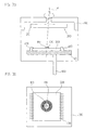
- FIG. 2 shows a schematic fragmentary view of a first exemplary embodiment of a rotary position measuring instrument in accordance with the present invention
- FIG. 3 a shows a lateral fragmentary view of the rotary position measuring instrument of FIG. 2 ;
- FIG. 3 b is a top view of an embodiment of a detector assembly used with the rotary position measuring instrument of FIG. 2 in accordance with the present invention
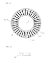
- FIG. 4 a is a top view of an embodiment of a graduated disk used with the rotary position measuring instrument of FIG. 2 in accordance with the present invention
- FIG. 4 b is a sectional view of a portion of the graduated disk of FIG. 4 a ;
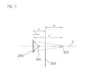
- FIG. 5 shows a schematic fragmentary view of a second exemplary embodiment of a rotary position measuring instrument in accordance with the present invention.
- FIG. 2 shows a first exemplary embodiment of a rotary position measuring instrument of the present invention, which is based on a central-projection scanning principle.
- a light source 10 is provided, which divergently illuminates a graduated disk that has a rotationally symmetrical, reflective measuring standard 20 . Between the light source 10 and the measuring standard 20 , no further interposed components are provided, which makes an especially compact design of the rotary position measuring instrument of the present invention possible.
- the measuring standard 20 on the graduated disk is embodied as a radial graduation, which includes graduation regions of different reflection properties disposed in a circle around the axis of rotation R.
- an incremental graduation with periodically disposed graduation regions of different reflectivity, or an absolute graduation with aperiodically disposed graduation regions of different periodicity may be provided.
- the incident beams are reflected back in the direction of the light source 10 , and in the detection plane the incident beams strike the rotationally symmetrical optoelectronic detector assembly 30 .
- the graduated disk having the measuring standard 20 is rotatable relative to the light source 10 and the detector assembly 30 about the axis of rotation R.
- the result in the detection plane is a circular-annular, modulated fringe pattern, which can be converted via the detector assembly 30 into rotary-angle-dependent position signals.
- the relative or absolute position of two objects rotatable relative to one another about the axis of rotation R can be determined.
- One of the two objects here is connected to the graduated disk or measuring standard 20 , and the other object is connected to the light source 10 and the detector assembly 30 .
- the two objects can, for instance, be machine parts that are rotatable relative to one another.
- the position signals generated via the position measuring instrument can be delivered to a machine controller, which uses them, for instance, for positioning the appropriate machine parts.
- the light source 10 is spaced apart on the axis of rotation R from the measuring standard 20 by the first distance u.
- the detector assembly 30 is spaced apart from the measuring standard 20 by the second distance v.
- the magnitude of the second distance v is selected to be different from the first distance u.
- an optical element effects a projection of an image of the light source 10 into a position on the axis of rotation R, which has a third distance u′ from the measuring standard 20 is provided in or integrated with the graduated disk; this third distance u′ differs in magnitude from the first distance u.
- the light source projected into this position that is, the light source image
- the beam path resulting from this image is indicated by dashed lines.
- the corresponding optical element in the graduated disk has been dimensioned such that the magnitude of the third distance u′ is identical to that of the second distance v.
- the selection of the magnitude of the third distance u′ to be identical to the second distance v is in no way essential to the present invention. That is, advantageous embodiments of the rotary position measuring instrument of the present invention can also be implemented with differently selected third distances u′.
- the optical element integrated with the graduated disk here has the optical effect of either a concave mirror or a convex mirror, each with a defined focal length f.
- the result is the optical effect of a concave mirror, and the focal length f is quantitatively larger than the object distance in the projection of an image by the concave mirror.
- the light source 10 is projected into the virtual light source 10 ′ at a position on the axis of rotation R that is at the third distance u′ from the measuring standard 20 .
- the optical effect of a concave mirror with the thus-determined focal length f must accordingly be ensured, so that a virtual projection of an image of the light source 10 into the desired position takes place, as shown.
- FIGS. 3 a , 3 b show various fragmentary views of a complete position measuring instrument.
- FIGS. 4 a , 4 b shown various views of the graduated disk, including the measuring standard, used in it.
- a detector assembly 300 is disposed on a stationary carrier board 500 .
- a light source 100 is placed centrally above the detector assembly 300 .
- the detector assembly 300 and the light source 100 are connected via bond wires 400 to signal lines—not shown in the drawings—in the carrier board 500 .
- the carrier board 500 is connected to a downstream electronics unit, also not shown, by way of which the position signals generated are transmitted and also by way of which the supply of current and voltage to the electronic components in the position measuring instrument is effected.
- the detector assembly 300 includes a circular-annular detector array 310 .
- the detector array 310 includes a plurality of individual detector elements disposed in a circular ring and periodically about the axis of rotation R.
- the graduated disk 210 is disposed rotatably about the axis of rotation R.
- the graduated disk 210 on the side toward the detector assembly 300 , has a reflective measuring standard 200 .
- An optical element integrated with the graduated disk 210 is provided, which has the optical effect described above, namely of projecting an image of the light source 100 at a position which has a third distance u′ from the measuring standard 200 .
- the optical element is embodied in the graduated disk 210 such that it has an optical effect like a concave mirror, as in the example of FIG. 2 , wherein the resultant third distance u′ is identical in magnitude to the second distance v.
- FIG. 4 a A top view on the graduated disk 210 in this exemplary embodiment is shown in FIG. 4 a
- a fragmentary cross-sectional view of the graduated disk 210 is shown in FIG. 4 b
- a reflective measuring standard 200 in the form of an incremental radial graduation which includes graduation regions 220 a , 220 b with different reflection properties that are disposed in a circular ring about the axis of rotation R.
- the graduation regions 220 a of the measuring standard 200 which are shown dark in FIG. 4 a , have a lesser reflectivity than the graduation regions 220 b located between them.
- the optical element which affects the defined projection of the image of the light source 100 is embodied via the radial graduated structures in the graduated disk 210 .
- the graduated disk 210 becomes a diffractive concave mirror with a defined focal length, by way of which the projection of the image of the light source 100 takes places, as explained.
- the selection of the relevant parameters of the graduated structures is based here on the known principle for designing diffractive elements for point-to-point image projection.
- a graduated disk 210 with a measuring standard 200 embodied in this way can be done, for example, first by creating the rotationally symmetrical graduated structure by depositing suitable films on a reflective carrier substrate and structuring them lithographically. Next, over the graduated structures the only slightly reflective graduation regions of the radial graduation are applied, for instance by depositing suitably absorbent materials.
- the graduated disk 210 it would also be possible to embody the graduated disk 210 by way of techniques known, for instance from the production of CDs. Then, in the only slightly reflective graduation regions, a diffractive fine structure is applied, which ensures that the light striking it does not reach the detector assembly, but instead is diffracted into other directions in space. Both these fine structures and the rotationally symmetrical graduated structures could first be molded in transparent plastic, for example, and then provided with a highly reflective metal film for instance of aluminum or gold.
- the optical effects in the graduated disk as a concave mirror
- an optical effect equivalent to a convex mirror can be attained via suitable graduated structures in the graduated disk.
- the focal length of the convex mirror is selected to be quantitatively greater than the object distance in the projection of an image by the convex mirror.
- FIG. 5 shows the scanning beam path of this exemplary embodiment in highly schematic form.
- a light source 1000 is provided, which is located next to the measuring standard 2000 at a first distance u away from it on the axis of rotation R. Analogous to the first exemplary embodiment of FIG. 3 , the detector assembly 3000 is spaced apart by the second distance v from the measuring standard 2000 .
- the measuring standard 2000 is embodied as a reflective measuring standard in the form of a radial graduation.
- the optical effects of FIG. 5 are embodied in the graduated disk.
- the optical effects affect the projection of an image of the light source 1000 into a defined position, which has the third distance u′ from the measuring standard 2000 .
- a virtual projection of an image of the light source 100 was effected via the optical element acting as a concave mirror.
- the optical element provided in the graduated disk is a real projection of the light source 1000 at the virtual light source image 1000 ′.
- the distance of the light source image 1000 ′ from the detector assembly 3000 is equivalent to a fourth distance w, which is identical in magnitude to the second distance v between the measuring standard 2000 and the detector assembly 3000 .
- the resultant third distance u′ here is not, as in the previous exemplary embodiment, identical in magnitude to the second distance v.
- the optical element acts as a concave mirror, but unlike the previous exemplary embodiment of FIG. 3 , the focal length of the concave mirror is quantitatively less than the object distance in the projection of an image by the concave mirror.
- the beams emitted by the virtual light source image 1000 ′ now pass first through the detector assembly 3000 , then strike the measuring standard 2000 , and finally, after reflection from the measuring standard 2000 , are propagated convergently in the direction of the detector assembly 3000 .
- an advantage of this exemplary embodiment proves not to be primarily the independence from fluctuations in the scanning distance, but the fact that there is a convergent beam path between the measuring standard 2000 and the detector assembly 3000 .
- the structures of the measuring standard 2000 are projected in reduced size into the detection plane, and accordingly even smaller detector surfaces in the detector assembly 3000 , compared to known systems of this kind, are sufficient.
- the result is once again an improved insensitivity to any soiling on the scanned measuring standard 2000 .
Landscapes
- Physics & Mathematics (AREA)
- General Physics & Mathematics (AREA)
- Optical Transform (AREA)
- Length Measuring Devices By Optical Means (AREA)
Applications Claiming Priority (3)
| Application Number | Priority Date | Filing Date | Title |
|---|---|---|---|
| DE102011082570.3 | 2011-09-13 | ||
| DE201110082570 DE102011082570A1 (de) | 2011-09-13 | 2011-09-13 | Rotatorische Positionsmesseinrichtung |
| DE102011082570 | 2011-09-13 |
Publications (2)
| Publication Number | Publication Date |
|---|---|
| US20130063732A1 US20130063732A1 (en) | 2013-03-14 |
| US8937726B2 true US8937726B2 (en) | 2015-01-20 |
Family
ID=46801323
Family Applications (1)
| Application Number | Title | Priority Date | Filing Date |
|---|---|---|---|
| US13/603,846 Active 2033-02-28 US8937726B2 (en) | 2011-09-13 | 2012-09-05 | Rotary position measuring instrument |
Country Status (5)
| Country | Link |
|---|---|
| US (1) | US8937726B2 (enExample) |
| EP (1) | EP2570780B1 (enExample) |
| JP (1) | JP6246460B2 (enExample) |
| CN (1) | CN102997948B (enExample) |
| DE (1) | DE102011082570A1 (enExample) |
Families Citing this family (4)
| Publication number | Priority date | Publication date | Assignee | Title |
|---|---|---|---|---|
| DE102012222077A1 (de) | 2012-12-03 | 2014-06-05 | Dr. Johannes Heidenhain Gmbh | Positionsmesseinrichtung |
| DE102016224012A1 (de) * | 2016-12-02 | 2018-06-07 | Dr. Johannes Heidenhain Gmbh | Positionsmesseinrichtung und Verfahren zum Betreiben einer Positionsmesseinrichtung |
| CN111458343B (zh) * | 2019-01-18 | 2024-08-06 | 深圳中科飞测科技股份有限公司 | 检测设备及检测方法 |
| JP7120200B2 (ja) * | 2019-10-15 | 2022-08-17 | 株式会社デンソー | 回転角検出装置 |
Citations (10)
| Publication number | Priority date | Publication date | Assignee | Title |
|---|---|---|---|---|
| US4572952A (en) * | 1982-07-28 | 1986-02-25 | Adrian March Research Ltd. | Position sensor with moire interpolation |
| US4844617A (en) * | 1988-01-20 | 1989-07-04 | Tencor Instruments | Confocal measuring microscope with automatic focusing |
| US5379132A (en) * | 1989-09-27 | 1995-01-03 | Canon Kabushiki Kaisha | Display apparatus for a head-up display system |
| JPH09133552A (ja) | 1995-11-08 | 1997-05-20 | Yaskawa Electric Corp | 光学式ロータリエンコーダ |
| US6429940B1 (en) * | 1999-02-26 | 2002-08-06 | Dr. Johannes Heidenhain Gmbh | Optical position measuring system employing a scale with multiple partial measuring graduations having different graduation periods |
| US20040090637A1 (en) * | 2002-08-07 | 2004-05-13 | Wolfgang Holzapfel | Interferential position measuring arrangement |
| US6885457B1 (en) * | 1998-08-01 | 2005-04-26 | Dr. Johannes Heidenhein Gmbh | Rotary position measuring system |
| US20070262250A1 (en) * | 2006-05-05 | 2007-11-15 | Ulrich Benner | Position-measuring device |
| WO2009144057A1 (de) * | 2008-05-31 | 2009-12-03 | Dr. Johannes Heidenhain Gmbh | Optische positionsmesseinrichtung |
| US20110286004A1 (en) * | 2010-05-21 | 2011-11-24 | Dr. Johannes Heidenhain Gmbh | Optical position measuring instrument |
Family Cites Families (12)
| Publication number | Priority date | Publication date | Assignee | Title |
|---|---|---|---|---|
| JPH07888Y2 (ja) * | 1988-02-22 | 1995-01-11 | 株式会社ミツトヨ | 光学式変位検出器 |
| JP2749900B2 (ja) * | 1989-09-11 | 1998-05-13 | 株式会社三協精機製作所 | 位置検出方法 |
| JP3500214B2 (ja) * | 1994-12-28 | 2004-02-23 | 日本電産コパル株式会社 | 光学式エンコーダ |
| JPH09105625A (ja) * | 1995-10-13 | 1997-04-22 | Topcon Corp | 距離測定装置 |
| JPH1123321A (ja) * | 1997-06-30 | 1999-01-29 | Canon Inc | 光学スケール及びそれを用いた変位情報測定装置 |
| JP3459755B2 (ja) * | 1997-06-30 | 2003-10-27 | キヤノン株式会社 | 変位情報測定装置 |
| JP2002139353A (ja) * | 2000-11-06 | 2002-05-17 | Olympus Optical Co Ltd | 光学式ロータリエンコーダ |
| GB0103582D0 (en) * | 2001-02-14 | 2001-03-28 | Renishaw Plc | Position determination system |
| DE102006042743A1 (de) * | 2006-09-12 | 2008-03-27 | Dr. Johannes Heidenhain Gmbh | Positionsmesseinrichtung |
| JP2008292352A (ja) * | 2007-05-25 | 2008-12-04 | Mitsutoyo Corp | 反射型エンコーダ |
| JP2009210374A (ja) * | 2008-03-04 | 2009-09-17 | Nikon Corp | エンコーダ及び受光ユニット |
| DE102008044858A1 (de) * | 2008-08-28 | 2010-03-04 | Dr. Johannes Heidenhain Gmbh | Optische Positionsmesseinrichtung |
-
2011
- 2011-09-13 DE DE201110082570 patent/DE102011082570A1/de not_active Withdrawn
-
2012
- 2012-08-29 EP EP12182164.9A patent/EP2570780B1/de active Active
- 2012-09-05 US US13/603,846 patent/US8937726B2/en active Active
- 2012-09-06 JP JP2012195723A patent/JP6246460B2/ja active Active
- 2012-09-13 CN CN201210338229.7A patent/CN102997948B/zh not_active Expired - Fee Related
Patent Citations (11)
| Publication number | Priority date | Publication date | Assignee | Title |
|---|---|---|---|---|
| US4572952A (en) * | 1982-07-28 | 1986-02-25 | Adrian March Research Ltd. | Position sensor with moire interpolation |
| US4844617A (en) * | 1988-01-20 | 1989-07-04 | Tencor Instruments | Confocal measuring microscope with automatic focusing |
| US5379132A (en) * | 1989-09-27 | 1995-01-03 | Canon Kabushiki Kaisha | Display apparatus for a head-up display system |
| JPH09133552A (ja) | 1995-11-08 | 1997-05-20 | Yaskawa Electric Corp | 光学式ロータリエンコーダ |
| US6885457B1 (en) * | 1998-08-01 | 2005-04-26 | Dr. Johannes Heidenhein Gmbh | Rotary position measuring system |
| US6429940B1 (en) * | 1999-02-26 | 2002-08-06 | Dr. Johannes Heidenhain Gmbh | Optical position measuring system employing a scale with multiple partial measuring graduations having different graduation periods |
| US20040090637A1 (en) * | 2002-08-07 | 2004-05-13 | Wolfgang Holzapfel | Interferential position measuring arrangement |
| US20070262250A1 (en) * | 2006-05-05 | 2007-11-15 | Ulrich Benner | Position-measuring device |
| WO2009144057A1 (de) * | 2008-05-31 | 2009-12-03 | Dr. Johannes Heidenhain Gmbh | Optische positionsmesseinrichtung |
| US20110109917A1 (en) * | 2008-05-31 | 2011-05-12 | Johanes Heidenhain GmbH | Optical position measuring device |
| US20110286004A1 (en) * | 2010-05-21 | 2011-11-24 | Dr. Johannes Heidenhain Gmbh | Optical position measuring instrument |
Non-Patent Citations (1)
| Title |
|---|
| Pettigrew, R.M., "Analysis of Grating Imaging and its Application to Displacement Meteorology," SPIE, vol. 36, 1st European Congress on Optics Applied to Meteorology (1977), pp. 325-332. |
Also Published As
| Publication number | Publication date |
|---|---|
| JP6246460B2 (ja) | 2017-12-13 |
| US20130063732A1 (en) | 2013-03-14 |
| EP2570780A3 (de) | 2017-01-11 |
| CN102997948A (zh) | 2013-03-27 |
| EP2570780A2 (de) | 2013-03-20 |
| EP2570780B1 (de) | 2018-01-03 |
| JP2013061330A (ja) | 2013-04-04 |
| DE102011082570A1 (de) | 2013-03-14 |
| CN102997948B (zh) | 2016-06-29 |
Similar Documents
| Publication | Publication Date | Title |
|---|---|---|
| CN103852090B (zh) | 位置测量装置 | |
| US7473886B2 (en) | Position-measuring device | |
| US7714273B2 (en) | Position-measuring device | |
| US7858922B2 (en) | Position-measuring device | |
| JP4724496B2 (ja) | 光学式エンコーダ | |
| CN102834690B (zh) | 位移测量方法和位移测量装置 | |
| CN102308186B (zh) | 光电位置测量装置和光电位置测量方法 | |
| US20120168615A1 (en) | Device and method for optically compensating for the measuring track decentralization in rotation angle sensors | |
| US20100134790A1 (en) | Optoelectronic longitudinal measurement method and optoelectronic longitudinal measurement device | |
| US8937726B2 (en) | Rotary position measuring instrument | |
| JPH02285214A (ja) | 測長器及びそれに用いるスケール部材 | |
| US7586621B2 (en) | Displacement-measuring optical scale and optical encoder using same | |
| CN102364307B (zh) | 位置检测装置 | |
| SE458153B (sv) | Optiskt vinkelmaetdon | |
| JP2011099869A (ja) | 光学式エンコーダ | |
| US7705289B2 (en) | Scanning unit for an optical position-measuring device | |
| CN113028998B (zh) | 光学位置测量装置 | |
| JPH07270121A (ja) | 位置センサ | |
| WO2007074752A1 (ja) | チルトセンサ及びエンコーダ | |
| JP2000266567A (ja) | ロータリエンコーダ | |
| JPH05126604A (ja) | 光学的位置検出器およびスケール製造方法 | |
| JPH04351918A (ja) | エンコーダ | |
| JPH04351919A (ja) | エンコーダ | |
| JPH0755507A (ja) | 光学式エンコーダ |
Legal Events
| Date | Code | Title | Description |
|---|---|---|---|
| AS | Assignment |
Owner name: DR. JOHANNES HEIDENHAIN GMBH, GERMANY Free format text: ASSIGNMENT OF ASSIGNORS INTEREST;ASSIGNOR:BENNER, ULRICH;REEL/FRAME:028959/0434 Effective date: 20120903 |
|
| FEPP | Fee payment procedure |
Free format text: PAYOR NUMBER ASSIGNED (ORIGINAL EVENT CODE: ASPN); ENTITY STATUS OF PATENT OWNER: LARGE ENTITY |
|
| STCF | Information on status: patent grant |
Free format text: PATENTED CASE |
|
| MAFP | Maintenance fee payment |
Free format text: PAYMENT OF MAINTENANCE FEE, 4TH YEAR, LARGE ENTITY (ORIGINAL EVENT CODE: M1551) Year of fee payment: 4 |
|
| MAFP | Maintenance fee payment |
Free format text: PAYMENT OF MAINTENANCE FEE, 8TH YEAR, LARGE ENTITY (ORIGINAL EVENT CODE: M1552); ENTITY STATUS OF PATENT OWNER: LARGE ENTITY Year of fee payment: 8 |