US8928172B2 - Booster control apparatus and an idling-stop system using the same - Google Patents
Booster control apparatus and an idling-stop system using the same Download PDFInfo
- Publication number
- US8928172B2 US8928172B2 US13/145,296 US200913145296A US8928172B2 US 8928172 B2 US8928172 B2 US 8928172B2 US 200913145296 A US200913145296 A US 200913145296A US 8928172 B2 US8928172 B2 US 8928172B2
- Authority
- US
- United States
- Prior art keywords
- target voltage
- voltage
- booster
- battery
- engine
- Prior art date
- Legal status (The legal status is an assumption and is not a legal conclusion. Google has not performed a legal analysis and makes no representation as to the accuracy of the status listed.)
- Expired - Fee Related, expires
Links
Images


Classifications
-
- F—MECHANICAL ENGINEERING; LIGHTING; HEATING; WEAPONS; BLASTING
- F02—COMBUSTION ENGINES; HOT-GAS OR COMBUSTION-PRODUCT ENGINE PLANTS
- F02D—CONTROLLING COMBUSTION ENGINES
- F02D29/00—Controlling engines, such controlling being peculiar to the devices driven thereby, the devices being other than parts or accessories essential to engine operation, e.g. controlling of engines by signals external thereto
- F02D29/02—Controlling engines, such controlling being peculiar to the devices driven thereby, the devices being other than parts or accessories essential to engine operation, e.g. controlling of engines by signals external thereto peculiar to engines driving vehicles; peculiar to engines driving variable pitch propellers
-
- F—MECHANICAL ENGINEERING; LIGHTING; HEATING; WEAPONS; BLASTING
- F02—COMBUSTION ENGINES; HOT-GAS OR COMBUSTION-PRODUCT ENGINE PLANTS
- F02D—CONTROLLING COMBUSTION ENGINES
- F02D17/00—Controlling engines by cutting out individual cylinders; Rendering engines inoperative or idling
- F02D17/04—Controlling engines by cutting out individual cylinders; Rendering engines inoperative or idling rendering engines inoperative or idling, e.g. caused by abnormal conditions
-
- F—MECHANICAL ENGINEERING; LIGHTING; HEATING; WEAPONS; BLASTING
- F02—COMBUSTION ENGINES; HOT-GAS OR COMBUSTION-PRODUCT ENGINE PLANTS
- F02N—STARTING OF COMBUSTION ENGINES; STARTING AIDS FOR SUCH ENGINES, NOT OTHERWISE PROVIDED FOR
- F02N11/00—Starting of engines by means of electric motors
- F02N11/08—Circuits or control means specially adapted for starting of engines
- F02N11/0814—Circuits or control means specially adapted for starting of engines comprising means for controlling automatic idle-start-stop
-
- F—MECHANICAL ENGINEERING; LIGHTING; HEATING; WEAPONS; BLASTING
- F02—COMBUSTION ENGINES; HOT-GAS OR COMBUSTION-PRODUCT ENGINE PLANTS
- F02N—STARTING OF COMBUSTION ENGINES; STARTING AIDS FOR SUCH ENGINES, NOT OTHERWISE PROVIDED FOR
- F02N11/00—Starting of engines by means of electric motors
- F02N11/08—Circuits or control means specially adapted for starting of engines
- F02N11/0862—Circuits or control means specially adapted for starting of engines characterised by the electrical power supply means, e.g. battery
- F02N11/0866—Circuits or control means specially adapted for starting of engines characterised by the electrical power supply means, e.g. battery comprising several power sources, e.g. battery and capacitor or two batteries
-
- B—PERFORMING OPERATIONS; TRANSPORTING
- B60—VEHICLES IN GENERAL
- B60W—CONJOINT CONTROL OF VEHICLE SUB-UNITS OF DIFFERENT TYPE OR DIFFERENT FUNCTION; CONTROL SYSTEMS SPECIALLY ADAPTED FOR HYBRID VEHICLES; ROAD VEHICLE DRIVE CONTROL SYSTEMS FOR PURPOSES NOT RELATED TO THE CONTROL OF A PARTICULAR SUB-UNIT
- B60W2510/00—Input parameters relating to a particular sub-units
- B60W2510/24—Energy storage means
- B60W2510/242—Energy storage means for electrical energy
- B60W2510/244—Charge state
-
- F—MECHANICAL ENGINEERING; LIGHTING; HEATING; WEAPONS; BLASTING
- F02—COMBUSTION ENGINES; HOT-GAS OR COMBUSTION-PRODUCT ENGINE PLANTS
- F02N—STARTING OF COMBUSTION ENGINES; STARTING AIDS FOR SUCH ENGINES, NOT OTHERWISE PROVIDED FOR
- F02N11/00—Starting of engines by means of electric motors
- F02N11/08—Circuits or control means specially adapted for starting of engines
- F02N2011/0881—Components of the circuit not provided for by previous groups
- F02N2011/0885—Capacitors, e.g. for additional power supply
-
- F—MECHANICAL ENGINEERING; LIGHTING; HEATING; WEAPONS; BLASTING
- F02—COMBUSTION ENGINES; HOT-GAS OR COMBUSTION-PRODUCT ENGINE PLANTS
- F02N—STARTING OF COMBUSTION ENGINES; STARTING AIDS FOR SUCH ENGINES, NOT OTHERWISE PROVIDED FOR
- F02N11/00—Starting of engines by means of electric motors
- F02N11/08—Circuits or control means specially adapted for starting of engines
- F02N2011/0881—Components of the circuit not provided for by previous groups
- F02N2011/0888—DC/DC converters
-
- Y—GENERAL TAGGING OF NEW TECHNOLOGICAL DEVELOPMENTS; GENERAL TAGGING OF CROSS-SECTIONAL TECHNOLOGIES SPANNING OVER SEVERAL SECTIONS OF THE IPC; TECHNICAL SUBJECTS COVERED BY FORMER USPC CROSS-REFERENCE ART COLLECTIONS [XRACs] AND DIGESTS
- Y02—TECHNOLOGIES OR APPLICATIONS FOR MITIGATION OR ADAPTATION AGAINST CLIMATE CHANGE
- Y02T—CLIMATE CHANGE MITIGATION TECHNOLOGIES RELATED TO TRANSPORTATION
- Y02T10/00—Road transport of goods or passengers
- Y02T10/10—Internal combustion engine [ICE] based vehicles
- Y02T10/40—Engine management systems
-
- Y02T10/48—
Definitions
- the present invention relates to a booster control apparatus, an idling-stop system using the same and a booster control method in an idling-stop vehicle.
- the idling-stop vehicle which performs an idling-stop for automatically stopping an engine for the time being when the vehicle stops due to the wait at traffic lights or the like.
- JP 2002-38984 discloses an arrangement in such an idling-stop vehicle in which a booster circuit for boosting the battery voltage is provided between the battery and an electrical load. The booster is activated when the battery voltage falls below a first set value due to an operation of a starter at the time of an engine start condition being met. The booster is stopped when the battery voltage increases above a second set value due to an operation of an alternator after the completion of the engine start.
- JP 2005-237149 discloses a technique directed to reducing such a change in the output voltage before and after the operation of the booster, wherein when the booster is activated in connection with the restart of the engine after the idling-stop, a target voltage of the booster is set based on the battery voltage immediately before the activation of the booster. Further, JP 2005-237149 discloses another embodiment in which the target voltage of the booster circuit is set in such a manner that voltage of the booster circuit is reduced gradually over a time with a predetermined voltage drop rate from the battery voltage immediately before the activation of the booster to a predetermined lower limit voltage.
- a booster control apparatus for controlling a booster provided between a battery and a load in an idling-stop vehicle in which a boosting operation of the booster is initiated in connection with a restart of an engine after an idling-stop, said booster control apparatus comprising:
- a first target voltage determination part configured to determine a first target voltage, based on a detected value or an estimated value of a voltage of the battery at the beginning of the idling-stop;
- a second target voltage determination part configured to determine a second target voltage, based on a detected value or an estimated value of a voltage of the battery at the beginning of the boosting operation of the booster;
- a target voltage setting part configured to set a target voltage for an output voltage of the booster
- a controlling part configured to control the booster based on the target voltage set by the target voltage setting part in such a manner that the output voltage of the booster follows the target voltage, wherein when the boosting operation of the booster is initiated in connection with the restart of the engine after the idling-stop, the target voltage setting part sets the target voltage in such a manner that the target voltage gradually increases from the second target voltage determined by the second target voltage determination part to the first target voltage determined by the first target voltage determination part.
- a booster control apparatus etc., can be obtained, by means of which a variation in an output voltage of the booster circuit at the time of an engine start (including a restart of an engine after an idling-stop) can be reduced.
- FIG. 1 is a diagram for illustrating a main configuration of an idling-stop system 1 in an idling-stop vehicle according to an embodiment of the present invention
- FIG. 2 is a diagram for illustrating a main function implemented by a booster control apparatus 22 ;
- FIG. 3 is a diagram for illustrating two examples of a target voltage pattern set in a target voltage pattern setting part 22 c;
- FIG. 4 is a flowchart for illustrating an example of determination processes in a first target voltage determination part 22 a and a second target voltage determination part 22 b and a target voltage pattern setting process in the target voltage pattern setting part 22 c;
- FIG. 5 is a flowchart for illustrating an example of a main process executed by a feedback control part 22 d;
- FIG. 6 is a diagram for illustrating a variation in an output voltage of the booster circuit 20 when the target voltage pattern according to the embodiment is applied;
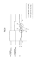
- FIG. 7 is a diagram for illustrating a variation in an output voltage of the booster circuit when the target voltage is set according to a first comparative example
- FIG. 8 is a diagram for illustrating a variation in an output voltage of the booster circuit when the target voltage is set according to a second comparative example.
- FIG. 9 is a diagram for illustrating a variation in an output voltage of the booster circuit when the target voltage is set according to a third comparative example.
- FIG. 1 is a diagram for illustrating a main configuration of an idling-stop system 1 in an idling-stop vehicle according to an embodiment of the present invention.
- the idling-stop system 1 mainly includes a battery 10 , an alternator 12 , a starter 18 , a booster circuit 20 , a booster control apparatus 22 , a load 30 and an EFI-ECU 50 .
- the battery 10 is mounted on the vehicle.
- the battery 10 may be a power source for supplying electrical power to electrical systems in the vehicle.
- the battery 10 is a rechargeable battery in a proffered embodiment.
- the battery 10 may be of various types, such as a lead acid battery, a nickel hydrogen battery, and a lithium ion battery; however, the lead acid battery is used in a proffered embodiment. Further, the battery 10 may include plural batteries or may include only one battery.
- the alternator 12 is mechanically connected to an engine 52 .
- the alternator 12 generates power using the rotation of the engine 52 .
- the alternator 12 is controlled by the EFI-ECU 52 , for example, which controls the engine 52 .
- the way of controlling the power generation of the alternator 12 may be arbitrary. For example, when the vehicle runs in a steady state or the engine 52 is idle, a target voltage to be generated by the alternator 12 is adjusted to such a value at which the electric discharge of the battery 10 doesn't occur. Further, when the vehicle slows down or the regenerative braking operates, the target voltage to be generated by the alternator 12 is adjusted to such a value which is greater than that when the vehicle runs in a steady state or the engine 52 is idle.
- the target voltage to be generated by the alternator 12 is set to zero as is the case with during the idling-stop (i.e., during the stop of the engine 52 ). In other words, the alternator 12 becomes inactive. It is noted that the battery 10 may be configured to accumulate electric energy generated by the alternator 12 during the traveling of the vehicle.
- the starter 18 is connected to the battery 10 .
- the starter 18 starts the engine 52 in the stop state using the electric energy from the battery when an engine start switch is operated to turn on or the idling-stop is terminated.
- the booster circuit 20 is a circuit for boosting the voltage supplied from the battery 10 to keep its output voltage at a constant voltage.
- the booster circuit 20 is connected to the battery 10 and the alternator 12 and supplies a stabilized output voltage to the load 30 .
- the battery voltage is input to an input terminal of the booster circuit 20 .
- the booster control apparatus 22 performs an on/off switching control (PWM control, for example) of a switching element (a power MOSFET, for example) with a variable duty ratio to keep the output voltage of the booster circuit 20 at a predetermined target voltage.
- PWM control for example
- a switching element a power MOSFET, for example
- the booster control apparatus 22 performs a feedback control to keep the output voltage the booster circuit 20 at a target voltage even if the voltage on the input side of the booster circuit 20 varies. Further, the booster control apparatus 22 stops the boosting operation temporarily when the output voltage exceeds the target voltage and thereafter restarts the boosting operation when the output voltage falls below the target voltage (see FIG. 5 ).
- the booster circuit 20 is switched between an active state and an inactive state under the control by the booster control apparatus 22 . If a boosting start signal supplied from the EFI-ECU 50 is in its OFF state, an inactive state of the booster circuit 20 (i.e., the status in which the booster circuit 20 is not operated) is implemented. In the inactive state in which the booster circuit 20 is turned off the input voltage of the booster circuit 20 is output as it is via a diode 72 , for example.
- the load 30 is connected to the output side of the booster circuit 20 and is connected to the battery 10 via the booster circuit 20 .
- the load 30 is an electrical load mounted on the vehicle.
- the type or the number of the loads 30 is arbitrary.
- the load 30 is auxiliary equipment which is easily affected by a change in the voltage applied and thus induces an unnatural feeling of a user, etc.
- the load 30 may include a lamp such as a head lamp, a tail lamp, etc., whose luminous intensity or intensity of illumination substantially changes because of a change in the voltage applied; an air conditioner (properly speaking, a blower motor) whose amount of air blown off substantially changes because of a change in the voltage applied; and a wiper (properly speaking, a wiper motor) whose wiping speed substantially changes because of a change in the voltage applied.
- the load 30 may include a meter and the like, a display device, etc.
- the booster control apparatus 22 controls the boosting operation of the booster circuit 20 as described above. The characterized portion of the way of this control is described later.
- the booster control apparatus 22 is configured mainly of a microprocessor that includes a CPU, a ROM in which control programs are stored, a RAM in which calculation results are stored, a timer, a counter, an input interface, an output interface, etc., for example, as is the case with an ordinary ECU. Further, the booster control apparatus 22 may include a purpose-built control circuit such as a feedback circuit (feedback control part 22 b described later), etc. Further, the booster control apparatus 22 is connected to a voltage detection circuit 40 for detecting the input voltage of the booster circuit 20 and a voltage detection circuit 42 for detecting the output voltage of the booster circuit 20 . The voltage detection circuits 40 and 42 may be incorporated in the booster control apparatus 22 .
- the EFI-ECU 50 performs an idling-stop control for reducing fuel consumption and an exhaust gas of carbon dioxide, etc., in addition to various controls of the engine 52 .
- the EFI-ECU 50 performs a final determination whether an idling-stop startup condition is met by checking whether other conditions for permitting the idling-stop, such as a condition as to a temperature of engine coolant, a condition as to a temperature of the battery 10 , a condition as to revolutions per minute of the engine 52 , are met. If the idling-stop startup condition is met, the EFI-ECU 50 sets an engine stop signal to its ON state to stop the engine 52 . In this way, operations such as fuel ejection and ignition are stopped without requiring a user to turn the ignition switch from an IG ON to an IG OFF, and consequently the engine 52 makes its transition from a running state to an inactive state.
- the EFI-ECU 50 determines whether an idling-stop termination condition is met based on determinations whether a shift range of a transmission if the vehicle is an Automatic Transmission (AT) vehicle is changed from “N (neutral)” range to “D (drive)” range or a brake pedal is released.
- the EFI-ECU 50 determines whether an idling-stop termination condition is met based on determinations whether a clutch pedal is pressed if the vehicle is a Manual Transmission (MT) vehicle.
- AT Automatic Transmission
- MT Manual Transmission
- the EFI-ECU 50 restarts the engine and supplies an ON signal of the boosting start signal to the booster control apparatus 22 .
- the starter 18 starts to operate without requiring a user to turn the ignition switch from an IG ON to a Starter ON, and consequently the engine 52 restarts.
- the EFI-ECU 50 supplies an OFF signal of the boosting start signal to the booster control apparatus 22 .
- the EFI-ECU 50 may supply an OFF signal of the boosting start signal to the booster control apparatus 22 .
- a part of the functions of the EFI-ECU 50 for example, a function of determining whether the respective conditions are met in the above-mentioned idling-stop control function
- the whole of the functions of the EFI-ECU 50 may be implemented by other ECU(s) or a similar control device (including the booster control apparatus 22 ).
- a part or the whole of the functions of the booster control apparatus 22 may be implemented by the EFI-ECU 50 or other ECU(s).
- FIG. 2 is a diagram for illustrating a main function implemented by the booster control apparatus 22 .
- the booster control apparatus 22 includes a first target voltage determination part 22 a , a second target voltage determination part 22 b , a target voltage pattern setting part 22 c and a feedback control part 22 d.
- the first target voltage determination part 22 a is supplied with the engine stop signal from the EFI-ECU 50 .
- the engine stop signal becomes ON state in order to cause the engine 52 to stop.
- the engine stop signal keeps its ON state when the engine is in its inactive state and keeps its OFF state when the engine is in its active state.
- a signal representing similar information for example, a signal representing that the idling-stop startup condition is met
- the first target voltage determination part 22 a is supplied with a detected value of the input voltage of the boost circuit 20 from the voltage detection circuit 40 . It is noted that since the alternator 12 is inactive during the idling-stop, the detected value of the input voltage of the boost circuit 20 from the voltage detection circuit 40 during the idling-stop corresponds to the voltage of the battery 10 (i.e., the battery voltage). It is also noted that instead of the detected value of the input voltage of the boost circuit 20 , a detected value of a voltage sensor which measures the voltage across the battery 10 may be used.
- the first target voltage determination part 22 a obtains a battery voltage (a detected value of the input voltage of the boost circuit 20 from the voltage detection circuit 40 ) at that time, and determines the obtained battery voltage as a first target voltage. It is noted that this battery voltage corresponds to the battery voltage at the time of stopping the engine 52 (i.e., at the time of starting the idling-stop).
- the time of stopping the engine 52 or the time of starting the idling-stop doesn't only indicate the precise instantaneous time point when the engine 52 stops and includes the times immediately before and after the time point when the engine 52 stops (or includes the times immediately before and after the time point when the idling-stop starts). This is because there is not substantial change in the battery voltage during a short period from the time immediately before the time of stopping the engine 52 to the time immediately after the time of stopping the engine 52 .
- the first target voltage determination part 22 a may use the battery voltage at the time of stopping the engine 52 as it is as a first target voltage. Alternatively, the first target voltage determination part 22 a may obtain the battery voltage at the time of stopping the engine 52 at several times (i.e., over time) and use the average value thereof as a first target voltage.
- the second target voltage determination part 22 b is supplied with the boosting start signal from the EFI-ECU 50 .
- the boosting start signal becomes ON state when the restart of the engine 52 is initiated after the idling-stop as mentioned above, and becomes OFF state when the restart of the engine 52 is completed and the voltage of the battery 10 is restored to the normal stable value due to the operation of the alternator 12 .
- the OFF timing of the boosting start signal is not limited to this example, and may be a timing when the restart of the engine 52 is completed or a timing thereafter.
- the boosting start signal may be changed to OFF state after a lapse of a predetermined fixed time from the time of starting the boosting provided that the restart of the engine 52 is completed. It is noted that instead of the ON signal of the boosting start signal a signal representing similar information (for example, a signal representing that the idling-stop termination condition is met) may be supplied.
- the second target voltage determination part 22 b is supplied with the detected value of the input voltage of the boost circuit 20 from the voltage detection circuit 40 . It is noted that since the alternator 12 is substantially inactive during the idling-stop or immediately after the restart of the engine 52 , the detected value of the input voltage of the boost circuit 20 from the voltage detection circuit 40 during such a time period corresponds to the voltage of the battery 10 (i.e., the battery voltage). It is also noted that instead of the detected value of the input voltage of the boost circuit 20 , a detected value of a voltage sensor which measures the voltage across the battery 10 may be used.
- the second target voltage determination part 22 b obtains a battery voltage (a detected value of the input voltage of the boost circuit 20 from the voltage detection circuit 40 ) at that time, and determines the obtained battery voltage as a second target voltage. It is noted that this battery voltage corresponds to the battery voltage at the time of starting the boosting operation of the booster circuit 20 (i.e., at the time of initiating the restart of the engine 52 ).
- the time of starting the boosting operation of the booster circuit 20 or the time of initiating the restart of the engine 52 doesn't only indicate the precise instantaneous time point when the boosting operation of the booster circuit 20 starts and includes the times immediately before and after the time point when the boosting operation of the booster circuit 20 starts (or includes the times immediately before and after the time point when the restart of the engine 52 is initiated). This is because there is not substantial change in the battery voltage during a short period from the time immediately before the time of starting the boosting operation of the booster circuit 20 to the time immediately after the time of starting the boosting operation of the booster circuit 20 . However, when the starter operates the battery voltage changes greatly. Thus, it is necessary to set the second target voltage based on the battery voltage before the operation of the starter 18 .
- the second target voltage determination part 22 b may use the battery voltage at the time of starting the boosting operation of the booster circuit 20 as it is as a second target voltage.
- the second target voltage determination part 22 b may obtain the battery voltage at the time of starting the boosting operation of the booster circuit 20 at several times (i.e., over time) and use the average value thereof as a second target voltage. It is noted that since the battery voltage falls gradually due to an electrical discharge of the battery 10 during the idling-stop, the second target voltage becomes lower than the first target voltage.
- the target voltage pattern setting part 22 c sets a changing pattern in time series of the target voltage (i.e., a target voltage pattern) based on the first target voltage obtained in the first target voltage determination part 22 a and the second target voltage obtained in the second target voltage determination part 22 b . Specifically, the target voltage pattern setting part 22 c sets the target voltage (the target voltage pattern) in such a manner that the target voltage gradually increases from the second target voltage to the first target voltage. The way of setting the target voltage pattern is described later with reference to FIG. 3 .
- the feedback control part 22 d is supplied with the detected value of the input voltage of the boost circuit 20 from the voltage detection circuit 40 , a detected value of the output voltage of the boost circuit 20 from the voltage detection circuit 42 and the boosting start signal from the EFI-ECU 50 .
- the feedback control part 22 d performs a feedback control of a switching operation (a duty ratio) of the switching element SW 1 based on the target voltage pattern (the target voltage varying in time series) set in the target voltage pattern setting part 22 c in such a manner that a pattern of the output voltage of the booster circuit 20 follows the target voltage pattern while monitoring the respective voltage values obtained from the voltage detection circuits 40 and 42 .
- FIG. 3 is a diagram for illustrating two examples of a target voltage pattern set in a target voltage pattern setting part 22 c.
- a portion (A) shows a waveshape of the boosting start signal in time series and a portion (B) shows the target voltage pattern.
- the boosting start signal becomes ON state, that is to say, the start of the boosting operation of the booster circuit 20 is instructed, at the time t 2 when the idling-stop termination condition is met, and the boosting start signal becomes OFF state at the time t 3 .
- an example of the target voltage pattern is indicated by P 1
- another example of the target voltage pattern is indicated by P 2 .
- the target voltage pattern P 1 is set in such a manner that the target voltage gradually increases from the second target voltage at the time t 2 to the first target voltage at the time t 3 . It is noted that in the illustrated example, the target voltage pattern P 1 shows that the target voltage increases in a linear manner; however, the target voltage may increase in a non-linear manner or a discontinuous manner.
- the target voltage pattern P 1 is suited for the case where the time period from the time t 2 to the time t 3 , that is to say, the time period from the time when the boosting start signal becomes ON state to the time when the boosting start signal becomes OFF state is a fixed value.
- the target voltage pattern P 2 is set in such a manner that the target voltage gradually increases from the second target voltage at the time t 2 to the first target voltage at the time t′ over time ⁇ t and thereafter (i.e., from time t′ to time t 3 ) stays at a constant value (i.e., the first target voltage). It is noted that in the illustrated example, the target voltage pattern P 2 shows that the target voltage increases in a linear manner; however, the target voltage may increase in a non-linear manner or a discontinuous manner.
- the time period ⁇ t from the time t 2 to the time t′ may be a fixed value or a variable value.
- the time period ⁇ t may be set to be shorter than a battery voltage restoring time which is taken for the battery voltage to be restored to its normal value.
- the battery voltage restoring time is determined based on the performance of the alternator 12 , the performance of the battery 10 and the operational status of the load 30 . It is noted that the battery voltage restoring time may be experimentally derived and the time period ⁇ t may be adapted to the derived battery voltage restoring time in advance. Alternatively, the battery voltage restoring time may be derived in real time because it could change dynamically.
- the time period ⁇ t may be adapted to the derived battery voltage restoring time in real time.
- the gradient of the target voltage pattern (and thus the time period ⁇ t) may be determined based on an upper tolerable value of a increasing rate of the battery voltage.
- the upper tolerable value of the increasing rate of the battery voltage is set to such a value at which the variation in the operation of the load 30 due to the increase of the battery voltage (for example, increase in luminous intensity of the lamp or the meter) doesn't become annoying for the user.
- about 0.5 V/100 ms may be adopted as an increasing rate (i.e., as the upper tolerable value of the increasing rate of the battery voltage) at which the increase in luminous intensity of the meter doesn't become annoying.
- FIG. 4 is a flowchart for illustrating an example of determination processes in the first target voltage determination part 22 a and the second target voltage determination part 22 b and a target voltage pattern setting process in the target voltage pattern setting part 22 c.
- step 400 in the first target voltage determination part 22 it is determined whether the engine stop signal from the EFI-ECU 50 becomes ON state. If it is determined that the engine stop signal from the EFI-ECU 50 becomes ON state, the process routine goes to step 402 .
- the first target voltage is determined based on the input voltage of the booster circuit 20 obtained from the voltage detection circuit 40 at this period (i.e., the latest detected value of the battery voltage).
- step 404 in the second target voltage determination part 22 b it is determined whether the boosting start signal from the EFI-ECU 50 becomes ON state. If it is determined that the boosting start signal from the EFI-ECU 50 becomes ON state, the process routine goes to step 406 . If it is determined that the boosting start signal from the EFI-ECU 50 becomes OFF state, the process routine waits until the boosting start signal from the EFI-ECU 50 becomes ON state.
- the second target voltage is determined based on the input voltage of the booster circuit 20 obtained from the voltage detection circuit 40 at this period (i.e., the latest detected value of the battery voltage). It is noted that there is a commonality between the first target voltage determined at step 402 and the second target voltage determined at step 406 in that they are set based on the detected value of the input voltage of the booster circuit 20 obtained from the voltage detection circuit 40 ; however, the first target voltage and the second target voltage are set based on the detected value of the input voltage of the booster circuit 20 obtained at different timing. Therefore, the first target voltage and the second target voltage are different from each other. In general, since the battery voltage falls gradually during the idling-stop, the second target voltage becomes lower than the first target voltage.
- the target voltage pattern of the booster circuit 20 is set based on the first target voltage determined at step 402 and the second target voltage determined at step 406 . Specifically, the target voltage pattern is set in a manner that the target voltage gradually increases from the second target voltage to the first target voltage (see FIG. 3 )
- the process routine proceeds to a process routine shown in FIG. 5 , which is described below.
- FIG. 5 is a flowchart for illustrating an example of a main process executed by the feedback control part 22 d .
- the process routine in FIG. 5 is executed subsequent to the above-mentioned process of step 408 in FIG. 4 .
- step 502 in the feedback control part 22 d it is determined whether the output voltage of the booster circuit 20 obtained from the voltage detection circuit 42 at this period (i.e., the latest detected value) is lower than the target voltage (i.e., the target voltage based on the target voltage pattern set in the target voltage pattern setting process shown in FIG. 4 ). If it is determined that the output voltage of the booster circuit 20 is lower than the target voltage, the process routine goes to step 504 . If it is determined that the output voltage of the booster circuit 20 is higher than or equal to the target voltage, the process routine goes to step 506 .
- step 504 in the feedback control part 22 d the boosting operation of the booster circuit 20 is activated (or kept being activated) based on the current target voltage (i.e., the target voltage based on the target voltage pattern set in the target voltage pattern setting process shown in FIG. 4 ). In other words, the feedback control is performed so as to make the output voltage of the booster circuit 20 follow the target voltage.
- the process routine goes to step 508 .
- step 506 in the feedback control part 22 d the boosting operation of the booster circuit 20 is deactivated (i.e., stopped).
- the process routine goes to step 508 .
- step 508 in the feedback control part 22 d it is determined whether the OFF signal of the boosting start signal is input from the EFI-ECU 50 . If it is determined whether the OFF signal of the boosting start signal is input from the EFI-ECU 50 , the process routine is terminated. On the other hand, it is determined whether the OFF signal of the boosting start signal is not input from the EFI-ECU 50 , the process routine goes to step 510 .
- the target voltage is updated based on the target voltage pattern (see FIG. 3 ) set in the target voltage pattern setting process shown in FIG. 4 .
- the target voltage to be used at the next period is set based on the target voltage pattern set in the target voltage pattern setting process shown in FIG. 4 .
- the process routine returns to step 502 after completing the process of step 510 , and then the process routine of the next period is executed.
- FIG. 6 is a diagram for illustrating a variation in an output voltage of the booster circuit 20 when the target voltage pattern according to the embodiment is applied.
- (A) shows a waveshape of the engine stop signal in time series
- (B) shows a waveshape of the boosting start signal in time series
- (C) shows a target voltage pattern (alternate long and short dashed line), a waveshape of a battery voltage (narrow line) and a waveshape of an output voltage of the booster circuit 20 (bold line) in time series.
- the idling-stop startup condition is met and thus the engine stop signal is set to its ON state
- the idling-stop termination condition is met and thus the boosting start signal is set to its ON state (i.e., the boosting operation of the booster circuit 20 is instructed to start)
- the boosting start signal is set to its OFF state.
- the battery voltage varies in the following manner. It is noted that in FIG. 6 (C), the battery voltage (narrow line) is the same as the output voltage of the booster circuit 20 (bold line) before time t 2 and after time t′′, and thus is not visible due to being overwritten by the output voltage (bold line). As shown in FIG. 6 (C), since the engine 52 and the alternator 12 are operated before time t 1 , the battery voltage and the output voltage of the booster circuit 20 maintains a substantially constant and relatively high value V H . At time t 1 , when the engine stop signal is set to its ON state, the engine 52 is stopped, and thus the alternator 12 is stopped. Thus, as shown in FIG. 6 (C), the battery voltage and the output voltage of the booster circuit 20 slowly decrease.
- the battery voltage and the output voltage of the booster circuit 20 stabilize at a substantially constant decreased value V L at time t p .
- the starter 18 is operated, and then the battery voltage steeply decreases. After that, when the restart of the engine 52 has succeeded, the starter 18 is stopped, and thus the battery voltage steeply increases. Further after that, the alternator 12 operates, and the battery voltage increases to be restored to the voltage before the execution of idling-stop.
- the target voltage pattern is set in the following manner.
- the values of the battery voltage detected at the timing indicated by “voltage detection” in the drawing are determined as the first target voltage and the second target voltage, respectively.
- the battery voltage (the alternator generation voltage) V H immediately before the ON signal of the engine stop signal becomes active i.e., engine stop
- the battery voltage V L immediately before the ON signal of the boosting start signal becomes active i.e., starting of the boosting operation
- the target voltage pattern (alternate long and short dashed line) is set in such a manner as shown in FIG. 3 . In other words, as shown in FIG.
- the target voltage is set to the second target voltage V L at time t 2 , and afterward the target voltage is set to increase toward the first target voltage V H gradually.
- the target voltage pattern (alternate long and short dashed line) is the same as the output voltage of the booster circuit 20 (bold line) from time t 2 to time t′′, and thus is not visible due to being overwritten by the output voltage (bold line).
- the output voltage of the booster circuit 20 varies in the following manner. Before time t 2 , since the booster circuit 20 is not operated, the output voltage of the booster circuit 20 varies in the same manner as the battery voltage, as mentioned above. Between time t 2 and time t′′ (when the output voltage exceeds the target voltage), since the booster circuit 20 is in operation, the output voltage of the booster circuit 20 slowly varies following the target voltage, in spite of the steep change of the battery voltage as mentioned above. After time t′′ when the output voltage exceeds the target voltage, since the booster circuit 20 is changed from its active state to its inactive state (see step 502 and step 506 in FIG. 5 ), the output voltage of the booster circuit 20 varies in the same manner as the battery voltage.
- the battery voltage is substantially restored to the voltage V H before the execution of idling-stop. Therefore, after time t′′, the variation in the output voltage of the booster circuit 20 is also small and the output voltage of the booster circuit 20 keeps a stable value.
- the target voltage of the booster circuit 20 is set in such a manner that the target voltage increases gradually from the battery voltage at the time of starting of the boosting operation to the battery voltage at the time of stopping of the engine.
- the target voltage of the booster circuit 20 is set in such a manner that the target voltage increases gradually from the battery voltage at the time of starting of the boosting operation to the battery voltage at the time of stopping of the engine.
- problems due to the steep changes in the output voltage of the booster circuit 20 such as blinking of lighting equipment, a steep variation in blower air flow, a steep variation in wiper speed, etc.
- FIG. 7 is a diagram for illustrating a variation in an output voltage of the booster circuit when the target voltage is set according to a first comparative example.
- (A) shows a waveshape of the engine stop signal in time series
- (B) shows a waveshape of the boosting start signal in time series
- (C) shows a waveshape of a battery voltage (narrow line) and a waveshape of an output voltage of the booster circuit (bold line) in time series.
- the target voltage is set to a constant value which is the battery voltage V L (see FIG. 6 ) immediately before the ON signal of the boosting start signal becomes active (i.e., starting of the boosting operation).
- the target voltage is set to the battery voltage V L at the time of starting of the boosting operation, there is no steep change appearing in the output voltage of the booster circuit at the time of starting of the boosting operation (around time t 2 ).
- the output voltage of the booster circuit is influenced directly by the steep increase of the battery voltage, and thus there is a steep variation appearing in the output voltage of the booster circuit. If such a steep variation in the output voltage of the booster circuit occurs, the problems such as blinking of lighting equipment, a steep variation in blower air flow, and a steep variation in wiper speed, etc., occur, as mentioned above.
- FIG. 8 is a diagram for illustrating a variation in an output voltage of the booster circuit when the target voltage is set according to a second comparative example.
- (A) shows a waveshape of the engine stop signal in time series
- (B) shows a waveshape of the boosting start signal in time series
- (C) shows a waveshape of a battery voltage (narrow line) and a waveshape of an output voltage of the booster circuit (bold line) in time series.
- the target voltage is set to a constant value which is the battery voltage V H (see FIG. 6 ) immediately before the ON signal of the engine stop signal becomes active (i.e., engine stop).
- FIG. 9 is a diagram for illustrating a variation in an output voltage of the booster circuit when the target voltage is set according to a third comparative example.
- (A) shows a waveshape of the engine stop signal in time series
- (B) shows a waveshape of the boosting start signal in time series
- (C) shows a waveshape of a battery voltage (narrow line) and a waveshape of an output voltage of the booster circuit (bold line) in time series.
- the target voltage of the booster circuit 20 is set in such a manner that the target voltage increases gradually from the battery voltage at the time of starting of boosting operation to the battery voltage at the time of stopping of the engine.
- the target voltage of the booster circuit 20 is set in such a manner that the target voltage increases gradually from the battery voltage at the time of starting of boosting operation to the battery voltage at the time of stopping of the engine.
- the detection of battery voltage used for determining the first target voltage and the second target voltage is triggered by the ON signal of the engine stop signal and the ON signal of the boosting start signal.
- the detection of the battery voltage at the time of stopping of the engine and the battery voltage at the time of starting of boosting operation is triggered by the ON signal of the engine stop signal and the ON signal of the boosting start signal.
- the detection of the battery voltage at the time of stopping of the engine and the battery voltage at the time of starting of boosting operation may be triggered by other equivalent signals.
- one of various signals by which the idling-stop startup condition is met may trigger the detection of the battery voltage at the time of stopping of the engine.
- one of various signals by which the idling-stop termination condition is met may trigger the detection of the battery voltage at the time of starting of boosting operation.
- the battery voltage at the time of stopping of the engine may be estimated based on other detected values or known design values.
- the battery voltage at the time of stopping of the engine may be estimated to be equivalent to the battery voltage when the vehicle is predicted to stop.
- the battery voltage (including an average battery voltage derived through the detection at several times) detected when the vehicle is predicted to stop may be set as the first target voltage.
- the vehicle stop may be predicted based on a vehicle speed signal (for example, change in a vehicle speed from a certain constant speed to a speed lower than a predetermined speed), a brake signal (for example, successive brake operations for a predetermined time period), an accelerator signal (for example, a pedal off operation of the accelerator pedal), or a combination thereof.
- the vehicle stop due to a red traffic light may be predicted based on positional information on an intersection from a navigation apparatus or positional information on a traffic light and positional information on the vehicle from a GPS receiver. Further, in addition to or instead of this, similarly, the vehicle stop due to a red traffic light may be predicted based on an image recognition result of the traffic light using a camera for monitoring a forward environment of the vehicle.
- the battery voltage including an average battery voltage derived through the detection at several times
- the battery voltage at the normal driving status may be set as the first target voltage.
- the battery voltage at the normal driving status may be estimated to be equal to a rated voltage of the battery 10 .
- the battery voltage at the time of starting of the boosting operation may be estimated based on other detected values or known design values. For example, an amount of a drop of the voltage during the idling-stop may be derived based on experiments or the like. In this case, the battery voltage at the time of starting of the boosting operation may be estimated by subtracting the amount of the drop of the voltage from the battery voltage at the time of stopping of the engine. Further, a voltage drop manner such as a gradient of the voltage drop during the idling-stop may be monitored.
- the battery voltage at the time of starting of the boosting operation may be estimated to be equivalent to the battery voltage when the voltage drop is reduced such as when the gradient of the voltage drop becomes substantially zero (i.e., the battery voltage around time t p in FIG. 6 (C)).
- the above-mentioned embodiment is related to the control when the booster circuit 20 is activated in connection with the restart of the engine 52 after the idling-stop.
- the booster circuit 20 is not operated in general. This is because in such a special situation of the ordinary start of the engine 52 a user has little concern for the blinking of lighting equipment, etc.
- the target voltage of the booster circuit 20 is set in such a manner that the target voltage increases gradually from the battery voltage at the time of starting of the boosting operation to the battery voltage at the time of stopping of the engine.
- the battery voltage at the time of stopping of the engine may be the battery voltage at the time of stopping of the engine detected at the previous trip (use) of the vehicle.
- the battery voltage at the normal driving status may be estimated to be equal to a rated voltage of the battery 10 . It is noted that in the case of the present invention being applied to the ordinary start of the engine the vehicle is not necessarily a vehicle in which the idling-stop system is provided.
Landscapes
- Engineering & Computer Science (AREA)
- Chemical & Material Sciences (AREA)
- Combustion & Propulsion (AREA)
- Mechanical Engineering (AREA)
- General Engineering & Computer Science (AREA)
- Power Engineering (AREA)
- Control Of Vehicle Engines Or Engines For Specific Uses (AREA)
- Dc-Dc Converters (AREA)
Applications Claiming Priority (1)
| Application Number | Priority Date | Filing Date | Title |
|---|---|---|---|
| PCT/JP2009/069282 WO2011058633A1 (ja) | 2009-11-12 | 2009-11-12 | 昇圧制御装置及びこれを用いるアイドリングストップシステム |
Publications (2)
| Publication Number | Publication Date |
|---|---|
| US20120212046A1 US20120212046A1 (en) | 2012-08-23 |
| US8928172B2 true US8928172B2 (en) | 2015-01-06 |
Family
ID=43991312
Family Applications (1)
| Application Number | Title | Priority Date | Filing Date |
|---|---|---|---|
| US13/145,296 Expired - Fee Related US8928172B2 (en) | 2009-11-12 | 2009-11-12 | Booster control apparatus and an idling-stop system using the same |
Country Status (5)
| Country | Link |
|---|---|
| US (1) | US8928172B2 (zh) |
| EP (1) | EP2500553B1 (zh) |
| JP (1) | JP4978734B2 (zh) |
| CN (1) | CN102132023B (zh) |
| WO (1) | WO2011058633A1 (zh) |
Cited By (1)
| Publication number | Priority date | Publication date | Assignee | Title |
|---|---|---|---|---|
| US20140278022A1 (en) * | 2013-03-12 | 2014-09-18 | Alpine Electronics, Inc. | Power supply device, on-vehicle electronic system, and method for controlling boosting circuit |
Families Citing this family (12)
| Publication number | Priority date | Publication date | Assignee | Title |
|---|---|---|---|---|
| KR101397023B1 (ko) * | 2012-03-23 | 2014-05-20 | 삼성에스디아이 주식회사 | 배터리 팩 및 배터리 팩의 제어 방법 |
| KR101361354B1 (ko) * | 2012-12-24 | 2014-02-10 | 현대자동차주식회사 | 부스트 컨버터의 승압 제어 방법 |
| CN104884770B (zh) * | 2012-12-27 | 2017-06-16 | 丰田自动车株式会社 | 车辆、控制装置及控制方法 |
| US9701312B2 (en) | 2013-12-11 | 2017-07-11 | Caterpillar Inc. | Idle reduction engine shutdown and restart system for a machine |
| JP5923126B2 (ja) * | 2014-02-18 | 2016-05-24 | 富士重工業株式会社 | バッテリ電圧の制御装置及びバッテリ電圧の制御方法 |
| US9745940B2 (en) | 2014-02-28 | 2017-08-29 | Caterpillar Inc. | Machine having hydraulic start assist system |
| JP6557503B2 (ja) * | 2015-04-22 | 2019-08-07 | 本田技研工業株式会社 | 燃料噴射弁用の昇圧制御装置 |
| JP6756202B2 (ja) * | 2016-09-12 | 2020-09-16 | トヨタ自動車株式会社 | 車両 |
| KR102500690B1 (ko) * | 2017-09-18 | 2023-02-17 | 삼성전자주식회사 | 배터리 상태를 기반으로 충전을 제어하는 방법 및 장치 |
| JP6839059B2 (ja) * | 2017-09-29 | 2021-03-03 | 株式会社デンソー | 電源制御装置 |
| US20190215378A1 (en) * | 2018-01-05 | 2019-07-11 | Cisco Technology, Inc. | Predicting vehicle dwell time to optimize v2i communication |
| CN110943504B (zh) * | 2018-09-21 | 2023-09-15 | 精工爱普生株式会社 | 移动设备 |
Citations (11)
| Publication number | Priority date | Publication date | Assignee | Title |
|---|---|---|---|---|
| JP2002038984A (ja) | 2000-07-25 | 2002-02-06 | Mitsubishi Motors Corp | アイドルストップ車両 |
| US20050067999A1 (en) * | 2002-01-16 | 2005-03-31 | Masaki Okamura | Voltage converter control apparatus, voltage conversion method, storage medium, program, drive system, and vehicle having the drive system |
| JP2005229756A (ja) | 2004-02-13 | 2005-08-25 | Toyota Motor Corp | 電圧発生装置、自動車、電圧発生装置の制御方法、自動車の制御方法、制御方法をコンピュータに実行させるためのプログラムを記憶したコンピュータ読取可能な記録媒体 |
| JP2005237149A (ja) | 2004-02-20 | 2005-09-02 | Toyota Motor Corp | 車両用電源装置 |
| US20060097579A1 (en) * | 2003-01-24 | 2006-05-11 | Mitsubishi Denki Kabushiki Kaisha | Power circuit for battery |
| JP2007056728A (ja) | 2005-08-23 | 2007-03-08 | Toyota Motor Corp | 車両用電源装置 |
| US20080012512A1 (en) * | 2006-07-13 | 2008-01-17 | Denso Corporation | Control apparatus for electric vehicles |
| US20080205086A1 (en) * | 2007-02-22 | 2008-08-28 | Lear Corporation | Inverter system |
| US20080203816A1 (en) * | 2007-02-28 | 2008-08-28 | Sanyo Electric Co., Ltd. | Power supply apparatus |
| JP2009142089A (ja) | 2007-12-07 | 2009-06-25 | Toyota Motor Corp | 車両用電源装置 |
| US7552705B2 (en) * | 2007-03-07 | 2009-06-30 | The Gates Corporation | Vehicle stop/start system with regenerative braking |
Family Cites Families (2)
| Publication number | Priority date | Publication date | Assignee | Title |
|---|---|---|---|---|
| JPH10176641A (ja) * | 1996-12-17 | 1998-06-30 | Denso Corp | 車載装置用電源回路 |
| JP2009013953A (ja) * | 2007-07-09 | 2009-01-22 | Toyota Motor Corp | エンジンの自動停止始動制御装置 |
-
2009
- 2009-11-12 US US13/145,296 patent/US8928172B2/en not_active Expired - Fee Related
- 2009-11-12 EP EP09847674.0A patent/EP2500553B1/en not_active Not-in-force
- 2009-11-12 CN CN2009801161243A patent/CN102132023B/zh not_active Expired - Fee Related
- 2009-11-12 JP JP2010527270A patent/JP4978734B2/ja not_active Expired - Fee Related
- 2009-11-12 WO PCT/JP2009/069282 patent/WO2011058633A1/ja active Application Filing
Patent Citations (12)
| Publication number | Priority date | Publication date | Assignee | Title |
|---|---|---|---|---|
| JP2002038984A (ja) | 2000-07-25 | 2002-02-06 | Mitsubishi Motors Corp | アイドルストップ車両 |
| US20050067999A1 (en) * | 2002-01-16 | 2005-03-31 | Masaki Okamura | Voltage converter control apparatus, voltage conversion method, storage medium, program, drive system, and vehicle having the drive system |
| US20060097579A1 (en) * | 2003-01-24 | 2006-05-11 | Mitsubishi Denki Kabushiki Kaisha | Power circuit for battery |
| JP2005229756A (ja) | 2004-02-13 | 2005-08-25 | Toyota Motor Corp | 電圧発生装置、自動車、電圧発生装置の制御方法、自動車の制御方法、制御方法をコンピュータに実行させるためのプログラムを記憶したコンピュータ読取可能な記録媒体 |
| US20070152641A1 (en) | 2004-02-13 | 2007-07-05 | Toyota Jidosha Kabushiki Kaisha | Voltage generator device, motor vehicle, control method for the voltage generator device, control method for the motor vehicle, and computer-readable recording medium storing program for causing computer to execute the control method |
| JP2005237149A (ja) | 2004-02-20 | 2005-09-02 | Toyota Motor Corp | 車両用電源装置 |
| JP2007056728A (ja) | 2005-08-23 | 2007-03-08 | Toyota Motor Corp | 車両用電源装置 |
| US20080012512A1 (en) * | 2006-07-13 | 2008-01-17 | Denso Corporation | Control apparatus for electric vehicles |
| US20080205086A1 (en) * | 2007-02-22 | 2008-08-28 | Lear Corporation | Inverter system |
| US20080203816A1 (en) * | 2007-02-28 | 2008-08-28 | Sanyo Electric Co., Ltd. | Power supply apparatus |
| US7552705B2 (en) * | 2007-03-07 | 2009-06-30 | The Gates Corporation | Vehicle stop/start system with regenerative braking |
| JP2009142089A (ja) | 2007-12-07 | 2009-06-25 | Toyota Motor Corp | 車両用電源装置 |
Non-Patent Citations (1)
| Title |
|---|
| International Search Report in International Application No. PCT/JP2009/069282; Dec. 8, 2009 (with English-language translation). |
Cited By (2)
| Publication number | Priority date | Publication date | Assignee | Title |
|---|---|---|---|---|
| US20140278022A1 (en) * | 2013-03-12 | 2014-09-18 | Alpine Electronics, Inc. | Power supply device, on-vehicle electronic system, and method for controlling boosting circuit |
| US9353719B2 (en) * | 2013-03-12 | 2016-05-31 | Alpine Electronics, Inc. | Power supply device, on-vehicle electronic system, and method for controlling boosting circuit |
Also Published As
| Publication number | Publication date |
|---|---|
| EP2500553A1 (en) | 2012-09-19 |
| US20120212046A1 (en) | 2012-08-23 |
| CN102132023A (zh) | 2011-07-20 |
| EP2500553B1 (en) | 2019-06-26 |
| JPWO2011058633A1 (ja) | 2013-03-28 |
| EP2500553A4 (en) | 2017-12-20 |
| CN102132023B (zh) | 2013-01-23 |
| WO2011058633A1 (ja) | 2011-05-19 |
| JP4978734B2 (ja) | 2012-07-18 |
Similar Documents
| Publication | Publication Date | Title |
|---|---|---|
| US8928172B2 (en) | Booster control apparatus and an idling-stop system using the same | |
| CN109591595B (zh) | 车辆及其定速巡航控制方法、装置和计算机可读存储介质 | |
| JP4474939B2 (ja) | 車両用電源装置 | |
| US20140330473A1 (en) | Vehicle control device, vehicle and vehicle control method | |
| US20150112578A1 (en) | Vehicular power-supply circuit | |
| JP2009240116A (ja) | 車両用発電機の制御装置 | |
| JP2007046508A (ja) | アイドルストップ制御装置およびアイドルストップ制御方法 | |
| KR20050069076A (ko) | 아이들 스톱 & 고 시스템 제어방법 | |
| JP3870903B2 (ja) | 車両用電源制御装置 | |
| JP2004232557A (ja) | 車両のエンジン制御装置 | |
| JP2006217765A (ja) | 車両用発電機の制御装置 | |
| JP2002155775A (ja) | エンジン自動制御装置 | |
| KR20100050786A (ko) | 아이들 스톱 앤드 고 차량의 램프 제어장치 및 방법 | |
| JP2009293451A (ja) | エンジン自動始動制御装置 | |
| KR102160964B1 (ko) | Epb 시스템의 고장 진단 방법 | |
| JP2016075237A (ja) | 車両用制御装置 | |
| JP2011247237A (ja) | アイドルストップ車の制御装置 | |
| JPH10153159A (ja) | 内燃機関の自動始動停止装置 | |
| KR101294491B1 (ko) | 전압 변환 장치를 이용한 알터네이터 발전 제어 시스템 | |
| JP5597083B2 (ja) | 車両の発電制御装置 | |
| KR102100782B1 (ko) | 슈퍼 커패시터를 구비한 공회전 제한 장치 및 공회전 제한 장치의 제어 방법 | |
| JP2003269211A (ja) | エンジン自動停止・自動再始動装置 | |
| JP2001341596A (ja) | 車両電装品の通電制御装置 | |
| JP2010138763A (ja) | アイドリングストップ車両用の電源装置 | |
| JP3849741B2 (ja) | 内燃機関の自動停止始動制御装置 |
Legal Events
| Date | Code | Title | Description |
|---|---|---|---|
| AS | Assignment |
Owner name: TOYOTA JIDOSHA KABUSHIKI KAISHA, JAPAN Free format text: ASSIGNMENT OF ASSIGNORS INTEREST;ASSIGNOR:GOTO, TOSHIO;REEL/FRAME:026617/0531 Effective date: 20100708 |
|
| STCF | Information on status: patent grant |
Free format text: PATENTED CASE |
|
| MAFP | Maintenance fee payment |
Free format text: PAYMENT OF MAINTENANCE FEE, 4TH YEAR, LARGE ENTITY (ORIGINAL EVENT CODE: M1551) Year of fee payment: 4 |
|
| FEPP | Fee payment procedure |
Free format text: MAINTENANCE FEE REMINDER MAILED (ORIGINAL EVENT CODE: REM.); ENTITY STATUS OF PATENT OWNER: LARGE ENTITY |
|
| LAPS | Lapse for failure to pay maintenance fees |
Free format text: PATENT EXPIRED FOR FAILURE TO PAY MAINTENANCE FEES (ORIGINAL EVENT CODE: EXP.); ENTITY STATUS OF PATENT OWNER: LARGE ENTITY |
|
| STCH | Information on status: patent discontinuation |
Free format text: PATENT EXPIRED DUE TO NONPAYMENT OF MAINTENANCE FEES UNDER 37 CFR 1.362 |
|
| FP | Lapsed due to failure to pay maintenance fee |
Effective date: 20230106 |