US8885317B2 - Micropulse bipolar corona ionizer and method - Google Patents
Micropulse bipolar corona ionizer and method Download PDFInfo
- Publication number
- US8885317B2 US8885317B2 US13/023,397 US201113023397A US8885317B2 US 8885317 B2 US8885317 B2 US 8885317B2 US 201113023397 A US201113023397 A US 201113023397A US 8885317 B2 US8885317 B2 US 8885317B2
- Authority
- US
- United States
- Prior art keywords
- ionizing
- positive
- pulse train
- negative
- voltage
- Prior art date
- Legal status (The legal status is an assumption and is not a legal conclusion. Google has not performed a legal analysis and makes no representation as to the accuracy of the status listed.)
- Active, expires
Links
- 238000000034 method Methods 0.000 title claims description 14
- 150000002500 ions Chemical class 0.000 claims abstract description 115
- 230000000694 effects Effects 0.000 claims description 13
- 238000013016 damping Methods 0.000 claims description 8
- 230000003068 static effect Effects 0.000 abstract description 6
- 230000005591 charge neutralization Effects 0.000 abstract description 5
- 239000007789 gas Substances 0.000 description 22
- 239000003990 capacitor Substances 0.000 description 14
- 230000009977 dual effect Effects 0.000 description 12
- MWUXSHHQAYIFBG-UHFFFAOYSA-N nitrogen oxide Inorganic materials O=[N] MWUXSHHQAYIFBG-UHFFFAOYSA-N 0.000 description 9
- 238000011109 contamination Methods 0.000 description 8
- 230000000670 limiting effect Effects 0.000 description 8
- CBENFWSGALASAD-UHFFFAOYSA-N Ozone Chemical compound [O-][O+]=O CBENFWSGALASAD-UHFFFAOYSA-N 0.000 description 7
- 230000002829 reductive effect Effects 0.000 description 7
- 239000004065 semiconductor Substances 0.000 description 6
- 230000010355 oscillation Effects 0.000 description 5
- 239000006227 byproduct Substances 0.000 description 3
- 230000007423 decrease Effects 0.000 description 3
- 230000003247 decreasing effect Effects 0.000 description 3
- 238000010586 diagram Methods 0.000 description 3
- 238000004519 manufacturing process Methods 0.000 description 3
- IJGRMHOSHXDMSA-UHFFFAOYSA-N Atomic nitrogen Chemical compound N#N IJGRMHOSHXDMSA-UHFFFAOYSA-N 0.000 description 2
- 239000000463 material Substances 0.000 description 2
- 230000001629 suppression Effects 0.000 description 2
- 229910000859 α-Fe Inorganic materials 0.000 description 2
- 230000005684 electric field Effects 0.000 description 1
- 230000005611 electricity Effects 0.000 description 1
- 239000007772 electrode material Substances 0.000 description 1
- 230000003628 erosive effect Effects 0.000 description 1
- 231100000206 health hazard Toxicity 0.000 description 1
- -1 ionizing waveform 64 Chemical class 0.000 description 1
- 238000006386 neutralization reaction Methods 0.000 description 1
- 230000003472 neutralizing effect Effects 0.000 description 1
- 229910052757 nitrogen Inorganic materials 0.000 description 1
- 239000002245 particle Substances 0.000 description 1
- 230000000007 visual effect Effects 0.000 description 1
Images


Classifications
-
- B—PERFORMING OPERATIONS; TRANSPORTING
- B03—SEPARATION OF SOLID MATERIALS USING LIQUIDS OR USING PNEUMATIC TABLES OR JIGS; MAGNETIC OR ELECTROSTATIC SEPARATION OF SOLID MATERIALS FROM SOLID MATERIALS OR FLUIDS; SEPARATION BY HIGH-VOLTAGE ELECTRIC FIELDS
- B03C—MAGNETIC OR ELECTROSTATIC SEPARATION OF SOLID MATERIALS FROM SOLID MATERIALS OR FLUIDS; SEPARATION BY HIGH-VOLTAGE ELECTRIC FIELDS
- B03C3/00—Separating dispersed particles from gases or vapour, e.g. air, by electrostatic effect
- B03C3/34—Constructional details or accessories or operation thereof
- B03C3/66—Applications of electricity supply techniques
- B03C3/68—Control systems therefor
-
- B—PERFORMING OPERATIONS; TRANSPORTING
- B03—SEPARATION OF SOLID MATERIALS USING LIQUIDS OR USING PNEUMATIC TABLES OR JIGS; MAGNETIC OR ELECTROSTATIC SEPARATION OF SOLID MATERIALS FROM SOLID MATERIALS OR FLUIDS; SEPARATION BY HIGH-VOLTAGE ELECTRIC FIELDS
- B03C—MAGNETIC OR ELECTROSTATIC SEPARATION OF SOLID MATERIALS FROM SOLID MATERIALS OR FLUIDS; SEPARATION BY HIGH-VOLTAGE ELECTRIC FIELDS
- B03C3/00—Separating dispersed particles from gases or vapour, e.g. air, by electrostatic effect
- B03C3/34—Constructional details or accessories or operation thereof
- B03C3/38—Particle charging or ionising stations, e.g. using electric discharge, radioactive radiation or flames
-
- H—ELECTRICITY
- H01—ELECTRIC ELEMENTS
- H01T—SPARK GAPS; OVERVOLTAGE ARRESTERS USING SPARK GAPS; SPARKING PLUGS; CORONA DEVICES; GENERATING IONS TO BE INTRODUCED INTO NON-ENCLOSED GASES
- H01T23/00—Apparatus for generating ions to be introduced into non-enclosed gases, e.g. into the atmosphere
Definitions
- the present invention relates to a micro-pulse bipolar corona ionizer for reducing or neutralizing positive and negative static charges on charged object. More particularly, the present invention relates to a micro-pulse bipolar corona ionizer that has an ion balance control circuit; a spark surge suppressor and corona activity circuit; a relatively low rate of emitter contamination; a relatively low corona-byproducts emission, such as ozone, nitrogen oxides and the like; or any combination of these features.
- AC corona ionizers are commonly used for static charge neutralization of charged objects. These ionizers, however, are prone to relatively high corona-byproducts emission, such as ozone and nitrogen oxides emissions in air, and a high rate of emitter contamination from the ambient environment. Emitter contamination decreases ionization efficiency and may affect ion balance, while ozone is a known health hazard. Consequently, a need exists for a solution for static charge neutralization that has a relatively low rate of emitter contamination, a relatively low ozone emission, ion balance control, or any combination of the foregoing.
- a solution for static charge neutralization that includes providing at least one pulse train pair to an emitter of an ionizer.
- the pulse train pair is disposed to include a positive pulse train and a negative pulse train that alternate in sequence.
- the positive pulse train includes an ionizing positive voltage waveform
- the negative pulse train includes an ionizing negative voltage waveform.
- Various alternative embodiments of the present invention are also disclosed, including an ion balance control circuit, a spark surge suppressor and corona activity circuit, or any combination of these circuits.
- FIG. 1 is a simplified exploded perspective view of a micro-pulse bipolar corona ionizer in accordance with one embodiment of the present invention
- FIG. 2 is an oscillator screen shot of a series of pulse train pairs with each pulse train pair including a positive pulse train and a negative pulse train in accordance with yet another embodiment of the present invention
- FIG. 3A depicts in block diagram form the sequence of positive and negative pulse trains that comprise an pulse train pair over time (T) in accordance with the embodiment of the present invention
- FIG. 3B depicts in block diagram form the sequence of negative and positive pulse trains that comprise an pulse train a pair over time (T) in accordance with an alternative embodiment of the present invention
- FIG. 4A is an oscillator screen shot of a positive pulse train that forms one portion of an pulse train pair in accordance with another embodiment of the present invention
- FIG. 4B is an oscillator screen shot of a negative pulse train that forms one portion of an pulse train pair in accordance with yet another embodiment of the present invention.
- FIG. 5A is a circuit diagram of an micro-pulse bipolar corona ionizer in accordance with yet another embodiment of the present invention.
- FIG. 5B is an example expanded view of the pulses shown in FIG. 5A ;
- FIG. 6A illustrates a method for creating bipolar ions by corona discharge by providing at least one pulse train pair to an emitter in accordance with yet another embodiment of the present invention.
- FIG. 6B illustrates optional additional steps to the method disclosed in FIG. 6A above in accordance with an alternative embodiment of the present invention.
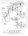
- FIG. 1 discloses a micro-pulse bipolar corona ionizer 10 that uses an ionizing electrode, named emitter 12 ; a conductive element or structure used as a reference electrode 14 ; a power supply 16 that is disposed to provide at least one voltage-alternating pulse train pair 18 to emitter 12 ; a gas source 20 disposed to provide a flow of gas 22 ; an ion balance circuit 24 that is electrically coupled to another electrode 26 , named ion balance electrode, and to a common reference bus 29 , such as ground; and a spark surge suppressor and corona activity circuit 28 coupled to reference electrode 14 and to common reference bus 29 .
- Power supply 16 is electrically coupled to common reference bus 29 , to reference electrode 14 through common reference bus 29 , and to emitter 12 .
- Pulse train pair 18 is received by emitter 12 and by reference electrode 14 through common reference bus 29 .
- pulse train pair 18 includes positive and negative pulse trains 30 and 32 that alternate in serial sequence.
- An upper dashed line 44 represents a positive corona threshold voltage, such as 4.5 kV
- a lower dashed line 46 represents a negative corona threshold voltage, such as ( ⁇ )4.25 kV.
- Each positive pulse train 30 is disposed to include an ionizing positive voltage waveform that has a maximum positive voltage amplitude which exceeds the voltage threshold for creating positive ions by corona discharge.
- negative pulse train 32 is disposed to include an ionizing negative voltage waveform that has a maximum negative voltage amplitude which exceeds the voltage threshold for creating negative ions by corona discharge.
- these respective positive and ionizing negative voltage waveforms alternatively create voltage gradients across a space 38 between emitter 12 and reference electrode 14 , generating by corona discharge an ion cloud that includes positive 34 and negative ions 36 .
- Using a serial sequence of pulse train pairs that each use positive and negative pulse trains provides efficient bipolar ionization for at least one emitter electrode.
- the number of pulse train pairs may be adjusted to maximize static charge neutralization or discharge of a target object, depending on the flow rate of gas blown or provided across an emitter, such as gas flow 22 and emitter 12 in FIG. 1 .
- the repetition rate for each pulse train 18 is not intended to be limiting in any way.
- the repetition rate can be adjusted accordingly to the power level desired for the embodiment disclosed in FIG. 2 can be set from one to several thousand times per second with a duty factor from 0.1% to 1%.
- the term duty factor may also be referred to herein as the effective ratio of pulse train power on versus pulse train power off per pulse train time period, such as pulse train time period 48 .
- Using a duty factor from 0.1% to 1% creates a very brief corona discharge, reducing ozone emissions as well as the rate of emitter contamination.
- the various embodiments of the present invention disclosed herein produces ozone emissions of concentrations of around 10 to 15 parts per billion (ppb), which is three to five times less than other types of known ionizers that use high frequency high-voltage alternating current to generate ions by corona discharge.
- the various embodiments disclosed herein also greatly reduce the rate of particle attraction to ionizer emitter(s), which in turn, reduces the rate of contamination of the emitter(s).
- pulse train 18 is disposed to include a positive pulse 30 train followed by a negative pulse train 32 in an alternating serial sequence.
- pulse train 18 may be disposed to include negative pulse train 32 followed by positive pulse train 30 in an alternating serial sequence.
- Positive and negative ions 34 and 36 may be also referred to collectively herein as a bipolar ion cloud 40 .
- a corona ionizer that uses pulse train pairs to generate a bipolar ion cloud may be referred to herein as a micro-pulse bipolar corona ionizer 10 .
- Emitter 12 may be formed from a loop of conducting wire but the use of a loop of emitter wire is not intended to be limiting in any way. Any emitter shape, such as a pointed electrode or other equivalents (not shown), may be used as alternatives. Emitter 12 may be made from any type of electrode material that can conduct electricity in a manner required to support the features described herein, including the creation of ions by corona discharge. Thus, emitter 12 may be made from a combination variety of materials, some of which may not be purely conductive, such as semiconductor, insulating or any combination of these materials.
- Reference electrode 14 is implemented in the form of a conducting fan guard but the use of this structure is not intended to be limiting.
- a separate non-conducting or conducting fan guard may be used in combination with a separately formed reference electrode.
- ion balance electrode 26 is implemented by using a conducting fan guard but the use of such a structure is not intended to be limiting.
- a separate fan guard may be used in combination with ion balance electrode 26 .
- Ion balance electrode 26 may be implemented by using any electrode that has a electrically conductive or semi-conductive surface, and may be placed at a location where bipolar ion cloud 40 will pass through, such as a location between target location 42 and the location where bipolar ion cloud 40 is created by the corona discharge.
- Bipolar ion cloud 40 is created by corona discharge generally within space 38 for the particular embodiment shown in FIG. 1 .
- Positive and negative pulse trains 30 and 32 may be referred to in the alternative as positive and negative micro-pulses, respectively.
- Gas source 20 may be used to enhance the mixing of positive and negative ions 34 and 36 , to enhance the range of delivery of positive and negative ions 34 and 36 to a selected target object (not shown) located at target location 42 to increase bipolar ion cloud density at target location 42 , or both.
- Gas source 20 in the embodiment shown is of a blower type, and employs a rotating fan to move air or gas through emitter 12 , reference electrode 14 and ion balance electrode 26 , such as gas flow 22 .
- the use, type, and placement location of gas source 20 are not intended to limit the scope and spirit of this disclosure in any way. For instance, as alternative embodiments and not illustrated in FIG. 1 , gas source 20 may be omitted, or if used, placed before emitter 12 so that gas or air may be blown or forced first through emitter 12 and then through reference electrode 14 and aimed towards a target location 42 .
- a fan-type gas source may be used as shown, or in alternative embodiments, compressed gas or air may be provided through a pipe, duct, plenum, or nozzle, a group of nozzles arranged on an ionizing bar, a nozzle surrounding at least a portion of an emitter, or the like (not shown).
- the configuration of gas flow 22 may be air, nitrogen, other gases, or any combination of these gases that is suitable for bipolar ion cloud delivery to target area 42 .
- Ion balance circuit 24 and ion balance electrode 26 may be used to balance ion current produced during the creation of bipolar ion cloud 40 by corona discharge. Ion balance circuit 24 is coupled to ion balance electrode 26 , common reference bus 29 , and power supply 16 .
- Ion balance circuit 24 generates a signal 31 that is received and used by power supply 16 to adjust the balance of positive and negative electrodes generated by pulse train pair 18 .
- Ion balance circuit 24 generates signal 31 by measuring the voltage 33 derived from positive and negative ions flowing past ion balance electrode 26 during operation. If voltage 33 is positive, ion balance circuit 24 adjusts signal 31 so that signal 31 causes power supply 16 to generate at least one pulse train pair, such as pulse train pair 18 , that creates more negative ions than positive ions. Similarly, if voltage 33 is negative, power supply 16 generates at least one pulse train pair that creates more positive ions than negative ions.
- Spark surge suppressor and corona activity circuit 28 is coupled to reference electrode 14 and common reference bus 29 and shunts a current (not shown) that can arise when a spark of voltage occurs between reference electrode 26 and common reference bus 29 . Spark surge suppressor and corona activity circuit 28 also provides a visual indicator that blinks in proportion to the amount of ions generated by micro-pulse bipolar corona ionizer 10 .
- spark surge suppressor and corona activity circuit 28 may be eliminated from the embodiment shown in FIG. 1 .
- reference electrode 14 may be directly coupled to common reference bus 29 .
- FIG. 4A is an oscillator screen shot of a positive pulse train 60 that forms one portion of an pulse train pair in accordance with another embodiment of the present invention.
- Pulse train pair 18 previously disclosed above with reference to FIGS. 2 and 3A 3 B, may be disposed to include a pulse train 60 , which includes two asymmetrical voltage waveforms, such as non-ionizing voltage waveform 62 , and ionizing voltage waveform 64 , which occur serially over a time period 68 .
- Non-ionizing and ionizing voltage waveforms 62 and 64 are followed by smaller negative and positive oscillations 69 .
- Negative and positive oscillations 69 are due to circuit resonance of the power supply used to generate pulse train 60 and are not intended to limit the present invention in anyway. Oscillations 69 may be completely reduced or eliminated by the use of a damping circuit as further disclosed below in FIG. 5A .
- At least one of the asymmetrical voltage waveforms such as ionizing voltage waveform 64 , has a maximum voltage amplitude 70 that exceeds the corona discharge voltage threshold necessary to create ions within a space between an emitter and reference electrode of a micro-pulse bipolar corona ionizer, such as space 38 , emitter 12 and reference electrode 14 , and ionizer 10 respectively disclosed above with FIG. 1 .
- These ions created by ionizing voltage waveform 64 have the same polarity as the voltage used by ionizing voltage waveform 64 , which in the example shown is a positive polarity.
- An ionizing voltage waveform that creates positive ions may be also referred to herein as an “ionizing positive voltage waveform”, such as ionizing voltage waveform 64 .
- the term “asymmetrical voltage waveforms” describes the voltage modulation profile of sequential waveforms that alternate in polarity and that have different maximum voltage amplitudes with one of the maximum voltage amplitudes exceeding the corona threshold necessary to create ions by corona discharge.
- a maximum amplitude 72 of non-ionizing voltage waveform 62 has a polarity (negative) that is opposite of the polarity (positive) of maximum amplitude 70 of ionizing waveform 64 .
- Non-ionizing voltage waveform 62 in the embodiment shown occurs before ionizing voltage waveform 64 and has a maximum amplitude 72 that is not sufficient to create ions by corona discharge.
- a non-ionizing voltage waveform that has a negative maximum voltage amplitude that is insufficient to create negative ions by corona discharge may be also referred to herein as a “non-ionizing negative voltage waveform”, such as non-ionizing voltage waveform 62 .
- a pulse train, such as pulse train 80 in FIG. 3B that includes a ionizing negative voltage waveform, which is a waveform that has a negative maximum voltage amplitude that exceeds the corona discharge voltage threshold necessary for creating negative ions, such as ionizing waveform 84 in FIG. 3B , is named herein as a “negative pulse train”.
- pulse train pair 18 has a pulse train sequence that starts with negative pulse train 32 followed by positive pulse train 30 .
- Using asymmetric voltage waveforms provides an efficient method for generating ions.
- the bipolar ion cloud oscillates in an area near emitter 12 that can be easily moved by an applied force, such as a gas flow or a superimposed electrical field. Because the period of ion generation is extremely short, corona byproduct emissions, such as ozone and nitrogen oxides is minimized and the rate of contamination on emitter 12 reduced.
- pulse train 80 in FIG. 4B is disposed to include two asymmetrical voltage waveforms, such as non-ionizing voltage waveform 82 and, ionizing voltage waveform 84 , which occur in sequence over a time period 88 .
- At least one of the asymmetrical voltage waveforms, such as ionizing voltage waveform 84 has a maximum voltage amplitude 90 that exceeds the corona discharge voltage threshold necessary to create ions within a space between an emitter and reference electrode of a micro-pulse bipolar corona ionizer, such as space 38 , emitter 14 and reference and micro-pulse bipolar corona ionizer 10 respectively disclosed above in FIG. 1 .
- Non-ionizing and ionizing voltage waveforms 82 and 84 are followed by smaller negative and positive oscillations 89 .
- Negative and positive oscillations 89 are created by the circuit resonance of the power supply used to generate pulse train 80 and are not intended to limit the present invention in anyway, and may be reduced or eliminated.
- Ions created by ionizing voltage waveform 84 have the same polarity as the voltage used by ionizing voltage waveform 84 , which in the example shown is a negative polarity.
- the maximum amplitude 92 of non-ionizing voltage waveform 82 has a polarity (positive) that is opposite of the polarity (negative) of maximum amplitude 90 of ionizing voltage waveform 84 .
- Non-ionizing voltage waveform 82 is not sufficient to create ions by corona discharge.
- Ionizing voltage waveform 84 may be also referred to herein as an “ionizing negative voltage waveform” because it can create negative ions by corona discharge.
- Non-ionizing waveform 82 may be referred to herein as a “non-ionizing positive voltage waveform” because it has a positive maximum voltage amplitude that is insufficient to create positive ions by corona discharge.
- a non-ionizing voltage waveform such as non-ionizing voltage waveform 62 or 82 , has rise and fall slew rates that are less than the rise and fall slew rates of the following ionizing waveform, such as ionizing waveform 64 or 84 corresponding to the same pulse train pair.
- a non-ionizing voltage waveform may be disposed to have a period of between 1 microsecond and 24 microseconds, and rise and fall slew rates that each range from 100 to 1000 Volts per microsecond.
- An ionizing voltage waveform such as ionizing voltage waveform 64 or 84 , has rise and fall slew rates that are each approximately 1000 to 5000 kilovolts per microsecond and a voltage waveform width of between 1 to 12 microseconds.
- each positive pulse train 60 in FIG. 4A generates positive ions.
- each negative pulse train 80 in FIG. 4B generates negative ions.
- FIG. 5A discloses a micro-pulse ionizer 120 that uses a wire emitter 122 , a reference electrode 124 , a power supply 126 disposed to provide at least one voltage-alternating pulse train pair 128 , a gas source 130 disposed to provide a flow of gas (not shown), an ion balance circuit 132 , an ion balance electrode 134 , a spark surge suppressor circuit and corona activity circuit 136 .
- Power supply 126 is electrically coupled to wire emitter 122 and a common reference bus, such as ground 139 , and is disposed to output pulse train pair 128 to wire emitter 122 during operation.
- Pulse train pair 128 includes a serial sequence of pulse trains.
- Each pulse train has a polarity that is opposite from the polarity of the other pulse train in voltage-alternating pulse train pair 128 .
- pulse train pair 128 and its pair of pulse trains may be respectively disposed to have the same function and characteristics previously described above for pulse train pair 18 , pulse train 60 and pulse train 80 .
- Emitter 122 , reference electrode 124 and gas source 130 may be implemented to have the same structure and function as described above with respect to emitter 12 , reference electrode 14 , and gas source 20 .
- Power supply 126 , ion balance circuit 132 , ion balance electrode 134 , and spark surge suppressor 136 may be implemented to have the same respective functions as power supply 16 , ion balance circuit 24 , ion balance electrode 26 and spark surge suppressor and corona activity circuit 28 previously disclosed above but are shown in FIG. 5A to have a particular circuit structure.
- power supply 126 includes a timer circuit 138 that generates a set of low voltage pulses 140 that each have a relatively short pulse duration 144 , a drive circuit 142 that is disposed to receive set of pulses 140 and a primary damping circuit 146 .
- Drive circuit 142 includes a D-Type flip-flop circuit 148 , named “dual delay circuit”, that has dual inverted outputs; a switching circuit 150 ; and transistors 152 and 154 .
- a set of pulses 140 are further illustrated in FIG. 5B .
- Timer circuit 138 and drive circuit 142 are collectively referred to as a pulse drive circuit 141 in this disclosure.
- Timer circuit 138 includes a timer IC 155 , a diode 156 , a resistor 158 , a capacitor 160 , and a resistor 162 .
- Timer IC 155 may be implemented by using any configurable general purpose timer, such as model number LMC555, which is available from National Semiconductor of Santa Clara, Calif.
- Timer IC 155 is an integrated circuit disposed to provide a configurable clock signal through a clock output 163 .
- these clock signals are used as pulses 140 .
- Diode 156 , resistor 158 and capacitor 160 establish the pulse duration 144 for pulse 140 (see FIGS. 4 and 5B ).
- Resistor 162 and capacitor 160 set the repetition rate for each pulse 140 .
- the repetition rate is equal to the inverse of pulse period 143 .
- diode 156 may be implemented using a diode having a marking code of 1N4248, while resistors 158 and 162 , and capacitor 160 have the following respective values: 1500 ohms, 240K ohms, and 0.01 ⁇ F (microfarads).
- LMC555 Low voltage is any voltage suitable for use with semiconductor components of the type described herein. Such semiconductor component voltages currently range in magnitude from 5 or 12, whether positive or negative, although in the embodiment disclosed herein positive low voltages of 5 and 12 volts are used.
- Dual delay circuit 148 is in the form of a D-type flip-flop that has two outputs which are inverted relative to each other. Dual delay circuit 148 may be implemented by using model number MM74C74 from Fairchild Semiconductor of San Jose, Calif. Dual delay circuit 148 is configured to provide two clock signals to switching circuit 150 . Switching circuit 150 may be implemented by using a commonly known integrated circuit that provides four dual input AND gates arranged in the manner shown, such as model number MC14081B, available from On Semiconductor Corporation of Phoenix, Ariz.
- Dual delay circuit 148 and switching circuit 150 alternately switch each pulse 140 between transistors 152 and 154 .
- Drive circuit 142 receives each pulse 140 , and routes each pulse 140 to clock input 161 from dual delay circuit 148 and to an input from each AND gate receive.
- the first output Q from dual delay circuit 148 is coupled to inputs 165 from two of the AND gates, and the second output (inverted Q) from dual delay circuit 148 is coupled to inputs 167 from the other two of the AND gates, and routed to the data pin of the switching circuit 148 .
- the preset and clear pins are coupled to a 12 volt source.
- pulse drive circuit 141 During the operation of power supply 126 , and for each pulse train generated, pulse drive circuit 141 enters a charging stage by causing a current to flow through one half of a primary coil 164 of high voltage transformer 166 for a selected duration. This time duration during which current passes through one half of primary coil 164 is set by and is approximately equivalent to pulse duration 144 of pulse 140 . Dual delay circuit 148 and switching circuit 150 alternately switch each pulse 140 between transistors 152 and 154 . Power supply 126 generates the asymmetrical waveforms of a positive pulse train, such as positive pulse train 30 or 60 in FIG.
- the stored energy produces a large positive pulse of voltage when the duration 144 of short pulse 140 expires, such as when trailing edge 145 of pulse 140 is reached, turning off transistor 152 abruptly and producing the large positive pulse of voltage (not shown) across primary coil 164 .
- Transformer 166 magnifies this large positive pulse of voltage and generates across secondary coil 170 a larger magnified ionizing waveform having a positive polarity.
- This large magnified voltage waveform is ultimately received by wire emitter 122 as an ionizing positive voltage waveform that forms a portion of a positive pulse train, such as ionizing positive voltage waveform 64 and positive pulse train 60 in FIG. 4A , respectively.
- Ionizing positive voltage waveform 64 is followed by smaller waveforms that oscillate between different polarities and with decreasing voltage amplitudes over time.
- the voltage amplitudes from these subsequent waveforms do not reach an ionizing voltage and are thus, non-ionizing voltage waveforms.
- These subsequent waveforms are caused by circuit resonance and can be controlled, eliminated or reduced by using primary damping circuit 146 .
- Power supply 126 generates the asymmetrical voltage waveforms for a negative pulse train, such as pulse train 32 or 80 in FIG. 2 or 4 B, in a manner similar to the generation of a positive pulse train as described immediately above. Power supply 126 , however, generates these asymmetrical waveforms for a negative pulse train when dual delay circuit and switching circuit 150 route a pulse 140 to the gate of transistor 154 , which causes pulse drive circuit 141 to enter into a charging stage. During this charging stage, transistor 154 causes a current to flow through center tap 165 and primary coil end 171 for a given duration. In the embodiment shown in FIG. 5A , this given duration during which current passes through primary coil 164 is set by and is approximately equivalent to pulse duration 144 .
- the current flowing through center tap 165 and primary coil end 171 produces a relatively small negative voltage pulse across one half of primary coil 164 and stores energy in primary coil 165 and in the air spaces and ferrite (if included) of high voltage transformer 166 .
- the direction of the current flow through the half portion primary coil 164 bounded by center tap 165 and primary coil end 171 during this charging stage is opposite from the direction of the current flow through the other half portion primary coil 164 , which is bounded by center tap 165 and primary coil end 169 used to generate a positive pulse train.
- both of these half portions of primary coil 164 are wound in the same direction.
- transformer 166 magnifies this small negative voltage waveform and produces a magnified positive voltage waveform across secondary coil 170 .
- This magnified positive voltage waveform is ultimately received by wire emitter 122 as the non-ionizing waveform of an asymmetrical voltage waveform that forms a portion of negative pulse train, such as non-ionizing positive voltage waveform 82 and negative pulse train 80 in FIG. 4B , respectively.
- the stored energy produces a large negative pulse of voltage when pulse duration 144 of short pulse 140 expires, such as when trailing edge 145 of pulse 140 is reached, turning off transistor 152 abruptly and producing the large negative pulse of voltage (not shown) across primary coil 164 .
- Transformer 166 magnifies this large negative pulse of voltage and generates across secondary coil 170 a larger magnified ionizing waveform having a negative polarity.
- This large magnified voltage waveform is ultimately received by wire emitter 122 as the ionizing negative voltage waveform of an asymmetrical voltage waveform that forms a portion of a negative pulse train, such as ionizing negative voltage waveform 84 and negative pulse train 80 in FIG. 4B , respectively.
- Ionizing negative voltage waveform 84 is followed by smaller waveforms that oscillate between different polarities and with decreasing voltage amplitudes over time.
- the voltage amplitudes from these subsequent waveforms do not reach an ionizing voltage and are thus, non-ionizing voltage waveforms.
- These subsequent waveforms are causing by circuit resonance and can be controlled, eliminated or reduced by using primary damping circuit 146 .
- High voltage transformer 166 is disposed to have a turns ratio of between 50 to 1 and 5000 to 1 on secondary coil 170 and primary coil 164 .
- transistor 154 causes the production of a negative pulse train
- transistor 152 causes the production of a positive pulse train, which collectively form a voltage-alternating pulse train pair that are ultimately received by emitter 122 and by reference electrode 124 through ground 137 , producing by corona discharge a bipolar ion cloud, such as bipolar ion cloud 40 in FIG. 1 .
- These positive and negative pulse trains have the same structure and function as positive and negative pulse trains 60 and 80 previously disclosed above in FIGS. 4A-4B , which respectively include a set of asymmetric waveforms, such as non-ionizing and ionizing voltage waveforms 62 - 64 , and 82 - 84 .
- the maximum voltage amplitude of the ionizing waveform, such as ionizing waveform 64 or 84 , for each pulse train produced at power supply output 168 is set according to the following variables:
- the primary damping circuit 146 which includes resistor 180 and capacitor 182 ;
- the impedance between transistor 154 and ground 137 which in the example shown in FIG. 5A is the resistance across the drain and source of transistor 177 .
- FIG. 5A In accordance with the embodiment of the present invention shown in FIG. 5A :
- the turns ratio of high voltage transformer 166 can range between 50 to 1 to 5000 to 1 for the secondary coil and primary coil;
- the primary coil inductance of high voltage transformer 164 is approximately 48 ⁇ H (microhenries) with each half portion approximately 14 ⁇ H;
- the pulse duration 144 of pulse 140 can range between one microsecond to 24 microseconds;
- resistor 176 and capacitor 178 are 1 to 100 ohms and 0.1 pF (picofarads), respectively;
- the resistance across the drain and source of transistor 177 can range from about 005 to 10 Ohms.
- These sequential asymmetrical waveforms comprise a pulse train, such as pulse train 60 or 80 , and are provided by power supply 126 at power supply output 168 .
- the inductance of primary coil 164 may be selected to be in the range of 10 to 100 ⁇ H and the load capacitance may be selected in the range of 3 to 60 pF. All values and model numbers of the circuit elements disclosed herein are not intended to limit the various embodiments disclosed herein. The actual values used will vary depending upon the dimensions and type of ionizer designed.
- Pulse trains generated by power supply 126 are disposed to have a relatively high slew rate, and, positive and negative pulse trains may be produced in a repeating sequential fashion by power supply 126 by using a relatively small-footprint high voltage transformer that does not include use multipliers, rectifiers, summing blocks or any combination of these components. Pulse repetition rate of each pulse train pair may be adjusted according to the gas flow used the distance of the target location containing the device selected for neutralization, the concentration of ions desired at the target location, or any combinations of these factors.
- Ion balance control circuit 132 in FIG. 5A includes transistor 177 , ion balance electrode 134 , resistor 184 , resistor 186 , and variable resistor 188 , sometimes referred to as a potentiometer, and capacitor 190 .
- transistor 177 Through transistor 177 , capacitor 190 , and potentiometer 192 , ion balance control circuit 132 is also coupled to ground 137 as shown.
- Resistors 184 and 186 produce a voltage at node 192 when ions flow past electrode 134 . This voltage is seen by the gate of transistor 177 , causing transistor 177 to change the resistance of transistor 177 across its source and drain.
- a small amount of bias current is added to the gate of transistor 177 by resistor 192 to compensate for the turn-on bias of transistor 177 .
- Capacitor 190 filters noise from pulses which may affect ion balance signal produced at node 192
- resistor 188 can be set to provide ion flow balance, such as zero, at the ion balance electrode or possibly at target object or target location, such as target location 42 in FIG. 1 .
- micro-pulse bipolar corona ionizer 120 begins to generate more positive then negative ions
- ion balance electrode 134 will acquire a positive charge.
- This positive charge creates a current flow across resistors 184 , 186 , and 188 , which increases the voltage at node 192 and at the gate of transistor 177 , and reduces the resistance across the source and drain of transistor 177 . Reducing the resistance across the source and drain of transistor 177 , increases the maximum voltage amplitude of the ionizing waveform of the negative pulse train, such as ionizing waveform 84 and negative pulse train 80 in FIG.
- node 192 acquires a reduced voltage or even a negative voltage, decreasing the voltage seen by the gate of transistor 177 , which raises the resistance of transistor 177 across its drain and source. This reduces the maximum voltage amplitude of the ionizing waveform from the negative pulse train, which in turn, reduces the production of negative ions until the voltage or charge at electrode 134 is sufficiently increased so that the ion balance at the target location previously selected is restored to approximately zero or to another preselected value.
- Spark surge suppressor and corona activity circuit 136 provides spark surge suppression and corona activity indicator functions.
- Diodes 194 and 196 , and capacitor 198 provide the spark surge suppression function. If a voltage spark occurs through reference electrode 124 , diode 194 shunts any resulting negative current through ground 137 , thus protecting the base of transistor 200 . Any positive spark surge current is shunted to ground 137 through diode 196 and capacitor 198 .
- Spark surge suppressor and corona activity circuit 136 provides the corona activity indicator function by using an electrode, such as reference electrode 124 , to receive ion current from wire emitter 122 and any currents from induced electrical corona noise signals which flow from to reference electrode 124 across the space separating reference electrode from wire emitter 122 .
- These currents are converted to voltage by inductor 202 , rectified by diode 196 and filtered by capacitor 198 , which collectively results in a voltage at node 204 and at the base of transistor 200 .
- a fluctuation in voltage at node 204 causes the voltage at the collector of transistor 200 to fluctuate in approximate proportion to the voltage at node 204 .
- Resistor 206 is coupled to the collector and to a 12 volt DC positive voltage and functions as a pull-down resistor.
- the anode end of LED 208 is coupled to the collector of transistor, while the cathode end of light emitting diode (LED) 208 is coupled to ground.
- a fluctuation of the voltage at the collector of transistor 200 causes LED 208 to flash or fluctuate as a function of the ion current generated by micro-pulse bipolar ionizer 120 .
- the voltage at the collector of transistor 200 may be sampled or used as an interrupt signal 210 by a microprocessor or equivalent (not shown) to enable the microprocessor to determine the state of ion generation.
- FIG. 6A illustrates a method for creating bipolar ions by corona discharge by providing at least one pulse train pair to an emitter in accordance with yet another embodiment of the present invention.
- at least one pulse train pair is provided to an emitter of an ionizer, such as pulse train pair 18 , emitter 12 and ionizer 10 in FIG. 1 .
- the pulse train pair is disposed to include a positive pulse train and a negative pulse train that alternate in sequence, such as positive and negative pulse trains 30 and 32 in FIG. 2 .
- the positive pulse train includes an ionizing positive voltage waveform and the negative pulse train including an ionizing negative voltage waveform. These ionizing positive and negative voltage waveforms alternately create voltage gradients across the emitter and the reference electrode, generating by corona discharge an ion cloud that includes positive and negative ions.
- FIG. 6B illustrates optional additional steps to the method disclosed in FIG. 6A above in accordance with an alternative embodiment of the present invention.
- a non-ionizing voltage waveform is generated before the ionizing waveform is generated for a pulse train.
- a non-ionizing negative voltage waveform may be generated before generating the ionizing positive waveform for a positive pulse train, such as positive pulse train 60 in FIG. 4A .
- a non-ionizing positive voltage waveform may be generated before generating the ionizing negative waveform for a negative pulse train, such as negative pulse train 80 in FIG. 4B .
- the non-ionizing voltage waveform is generated on a secondary coil of a high voltage transformer by storing energy on a primary coil of the transformer, such as secondary coil 170 , high voltage transformer 166 , and primary coil 164 in FIG. 5A , respectively.
- a voltage across this primary coil is generated when the energy charge is released, generating an ionizing voltage waveform across the secondary coil.
Landscapes
- Engineering & Computer Science (AREA)
- Automation & Control Theory (AREA)
- Elimination Of Static Electricity (AREA)
- Electrostatic Separation (AREA)
- Plasma Technology (AREA)
Priority Applications (8)
| Application Number | Priority Date | Filing Date | Title |
|---|---|---|---|
| US13/023,397 US8885317B2 (en) | 2011-02-08 | 2011-02-08 | Micropulse bipolar corona ionizer and method |
| TW101103565A TWI458213B (zh) | 2011-02-08 | 2012-02-03 | 微脈衝雙極電暈游離裝置與方法 |
| US13/367,369 US8773837B2 (en) | 2007-03-17 | 2012-02-06 | Multi pulse linear ionizer |
| JP2013553488A JP6018088B2 (ja) | 2011-02-08 | 2012-02-07 | コロナ放電式マイクロパルスバイポーライオナイザー及び方法 |
| PCT/US2012/024095 WO2012109206A1 (en) | 2011-02-08 | 2012-02-07 | Micropulse bipolar corona ionizer and method |
| KR1020137021728A KR101951682B1 (ko) | 2011-02-08 | 2012-02-07 | 마이크로펄스 바이폴라 코로나 이온화기 및 방법 |
| EP12704597.9A EP2673092B1 (en) | 2011-02-08 | 2012-02-07 | Micropulse bipolar corona ionizer and method |
| CN201280016280.4A CN103501914B (zh) | 2011-02-08 | 2012-02-07 | 微脉冲双极性电晕离子发生器及方法 |
Applications Claiming Priority (1)
| Application Number | Priority Date | Filing Date | Title |
|---|---|---|---|
| US13/023,397 US8885317B2 (en) | 2011-02-08 | 2011-02-08 | Micropulse bipolar corona ionizer and method |
Related Child Applications (2)
| Application Number | Title | Priority Date | Filing Date |
|---|---|---|---|
| US12/049,350 Continuation-In-Part US8009405B2 (en) | 2007-03-17 | 2008-03-16 | Low maintenance AC gas flow driven static neutralizer and method |
| US13/367,369 Continuation-In-Part US8773837B2 (en) | 2007-03-17 | 2012-02-06 | Multi pulse linear ionizer |
Publications (2)
| Publication Number | Publication Date |
|---|---|
| US20120200982A1 US20120200982A1 (en) | 2012-08-09 |
| US8885317B2 true US8885317B2 (en) | 2014-11-11 |
Family
ID=45688259
Family Applications (1)
| Application Number | Title | Priority Date | Filing Date |
|---|---|---|---|
| US13/023,397 Active 2032-11-13 US8885317B2 (en) | 2007-03-17 | 2011-02-08 | Micropulse bipolar corona ionizer and method |
Country Status (7)
| Country | Link |
|---|---|
| US (1) | US8885317B2 (enExample) |
| EP (1) | EP2673092B1 (enExample) |
| JP (1) | JP6018088B2 (enExample) |
| KR (1) | KR101951682B1 (enExample) |
| CN (1) | CN103501914B (enExample) |
| TW (1) | TWI458213B (enExample) |
| WO (1) | WO2012109206A1 (enExample) |
Cited By (8)
| Publication number | Priority date | Publication date | Assignee | Title |
|---|---|---|---|---|
| US9125284B2 (en) | 2012-02-06 | 2015-09-01 | Illinois Tool Works Inc. | Automatically balanced micro-pulsed ionizing blower |
| USD743017S1 (en) | 2012-02-06 | 2015-11-10 | Illinois Tool Works Inc. | Linear ionizing bar |
| US9380689B2 (en) | 2008-06-18 | 2016-06-28 | Illinois Tool Works Inc. | Silicon based charge neutralization systems |
| US9700643B2 (en) | 2014-05-16 | 2017-07-11 | Michael E. Robert | Sanitizer with an ion generator |
| US9808547B2 (en) | 2013-04-18 | 2017-11-07 | Dm Tec, Llc | Sanitizer |
| US9918374B2 (en) | 2012-02-06 | 2018-03-13 | Illinois Tool Works Inc. | Control system of a balanced micro-pulsed ionizer blower |
| US9950086B2 (en) | 2014-03-12 | 2018-04-24 | Dm Tec, Llc | Fixture sanitizer |
| US10124083B2 (en) | 2015-06-18 | 2018-11-13 | Dm Tec, Llc | Sanitizer with an ion generator and ion electrode assembly |
Families Citing this family (17)
| Publication number | Priority date | Publication date | Assignee | Title |
|---|---|---|---|---|
| US8773837B2 (en) | 2007-03-17 | 2014-07-08 | Illinois Tool Works Inc. | Multi pulse linear ionizer |
| US8885317B2 (en) | 2011-02-08 | 2014-11-11 | Illinois Tool Works Inc. | Micropulse bipolar corona ionizer and method |
| US20090316325A1 (en) * | 2008-06-18 | 2009-12-24 | Mks Instruments | Silicon emitters for ionizers with high frequency waveforms |
| US10548439B2 (en) | 2011-04-07 | 2020-02-04 | Excel Dryer, Inc. | Sanitizing hand dryer |
| US9421291B2 (en) * | 2011-05-12 | 2016-08-23 | Fifth Third Bank | Hand dryer with sanitizing ionization assembly |
| EP2812964B1 (en) * | 2012-02-06 | 2020-09-02 | Illinois Tool Works Inc. | Multi pulse linear ionizer |
| DE102012207219B4 (de) * | 2012-04-30 | 2017-11-23 | Gema Switzerland Gmbh | Antistatikvorrichtung und zugehöriges Betriebsverfahren |
| GB2521457A (en) * | 2013-12-20 | 2015-06-24 | Isis Innovation | Charge stabilized dielectric film for electronic devices |
| TWI652869B (zh) * | 2014-03-19 | 2019-03-01 | 美商伊利諾工具工程公司 | 自動平衡的微脈衝離子化吹風器 |
| JP5613347B1 (ja) * | 2014-05-12 | 2014-10-22 | 株式会社 片野工業 | イオン・オゾン風発生装置及び方法 |
| CN104689918A (zh) * | 2015-03-23 | 2015-06-10 | 中冶赛迪工程技术股份有限公司 | 一种湿式电除尘器 |
| CN106300020B (zh) * | 2015-05-12 | 2017-12-22 | 威驰股份有限公司 | 数位高周波离子产生装置 |
| DE102015113656A1 (de) * | 2015-08-18 | 2017-02-23 | Epcos Ag | Plasmagenerator und Verfahren zur Einstellung eines Ionenverhältnisses |
| CN105655228B (zh) * | 2015-12-31 | 2017-07-28 | 同方威视技术股份有限公司 | 一种电晕放电组件、离子迁移谱仪和电晕放电方法 |
| DE102016008900B4 (de) | 2016-07-22 | 2020-08-06 | Audi Ag | Belüftungsanordnung mit einer Ionisationsvorrichtung für ein Fahrzeug |
| CN109351479A (zh) * | 2018-10-26 | 2019-02-19 | 刘彦恺 | 一种新型多功能静电除尘器 |
| CN120835518B (zh) * | 2025-09-19 | 2025-12-16 | 上海摩软通讯技术有限公司 | 离子风散热机构及电子设备 |
Citations (85)
| Publication number | Priority date | Publication date | Assignee | Title |
|---|---|---|---|---|
| US3875035A (en) | 1971-08-25 | 1975-04-01 | Purification Sciences Inc | Solid state frequency converter for corona generator |
| US4138233A (en) | 1976-06-21 | 1979-02-06 | Senichi Masuda | Pulse-charging type electric dust collecting apparatus |
| US4417293A (en) | 1980-10-14 | 1983-11-22 | Office National D'etudes Et De Recherches Aerospatiales | Methods and apparatus for transferring electric charges of different signs into a space zone, and application to static electricity eliminators |
| US4442356A (en) | 1981-08-21 | 1984-04-10 | International Business Machines Corporation | Corona wire assembly and method |
| US4689715A (en) | 1986-07-10 | 1987-08-25 | Westward Electronics, Inc. | Static charge control device having laminar flow |
| JPS63143954A (ja) | 1986-12-03 | 1988-06-16 | ボイエイジヤ−.テクノロジ−ズ | 空気イオン化方法及び装置 |
| US4781736A (en) | 1986-11-20 | 1988-11-01 | United Air Specialists, Inc. | Electrostatically enhanced HEPA filter |
| US4878149A (en) | 1986-02-06 | 1989-10-31 | Sorbios Verfahrenstechnische Gerate Und Gmbh | Device for generating ions in gas streams |
| US4901194A (en) | 1988-07-20 | 1990-02-13 | Ion Systems, Inc. | Method and apparatus for regulating air ionization |
| EP0386318A1 (en) | 1989-03-07 | 1990-09-12 | Takasago Thermal Engineering Co. Ltd. | Equipment for removing static electricity from charged articles existing in clean space |
| US5005101A (en) | 1989-01-31 | 1991-04-02 | Gallagher James C | Method and apparatus for negative charge effect and separation of undesirable gases |
| US5047892A (en) | 1989-03-07 | 1991-09-10 | Takasago Thermal Engineering Co., Ltd. | Apparatus for removing static electricity from charged articles existing in clean space |
| US5055963A (en) | 1990-08-15 | 1991-10-08 | Ion Systems, Inc. | Self-balancing bipolar air ionizer |
| US5095400A (en) | 1988-12-06 | 1992-03-10 | Saito Kohki Co., Ltd. | Method and apparatus for eliminating static electricity |
| US5116583A (en) | 1990-03-27 | 1992-05-26 | International Business Machines Corporation | Suppression of particle generation in a modified clean room corona air ionizer |
| JPH0435958Y2 (enExample) | 1987-03-11 | 1992-08-25 | ||
| JPH0547490A (ja) | 1991-08-19 | 1993-02-26 | Shishido Seidenki Kk | 除電装置 |
| US5249094A (en) | 1990-03-22 | 1993-09-28 | Asahi Glass Company Ltd. | Pulsed-DC ionizer |
| JPH06275366A (ja) | 1993-03-22 | 1994-09-30 | Takasago Thermal Eng Co Ltd | 帯電物品の中和装置 |
| US5388769A (en) | 1993-09-20 | 1995-02-14 | Illinois Tool Works Inc. | Self-cleaning ionizing air gun |
| US5447763A (en) | 1990-08-17 | 1995-09-05 | Ion Systems, Inc. | Silicon ion emitter electrodes |
| JPH07249497A (ja) | 1994-03-11 | 1995-09-26 | Yokogawa Denshi Kiki Kk | 除電器のバランス調整回路 |
| US5535089A (en) | 1994-10-17 | 1996-07-09 | Jing Mei Industrial Holdings, Ltd. | Ionizer |
| US5550703A (en) | 1995-01-31 | 1996-08-27 | Richmond Technology, Inc. | Particle free ionization bar |
| US5630949A (en) | 1995-06-01 | 1997-05-20 | Tfr Technologies, Inc. | Method and apparatus for fabricating a piezoelectric resonator to a resonant frequency |
| JPH1055896A (ja) | 1996-08-07 | 1998-02-24 | Toshiba Chem Corp | イオナイザー |
| JPH10156213A (ja) | 1996-11-29 | 1998-06-16 | Toto Ltd | 空気清浄装置 |
| US5847917A (en) | 1995-06-29 | 1998-12-08 | Techno Ryowa Co., Ltd. | Air ionizing apparatus and method |
| JPH11273893A (ja) | 1998-03-26 | 1999-10-08 | Kazuo Okano | 噴射型イオン発生装置 |
| JP2000058290A (ja) | 1998-06-04 | 2000-02-25 | Keyence Corp | 除電装置 |
| JP2000133413A (ja) | 1998-10-27 | 2000-05-12 | Shishido Seidenki Kk | イオン生成装置 |
| WO2000038484A1 (en) | 1998-12-22 | 2000-06-29 | Illinois Tool Works, Inc. | Gas-purged ionizers and methods of achieving static neutralization thereof |
| US6145391A (en) | 1998-03-04 | 2000-11-14 | Regents Of The University Of Minnesota | Charged particle neutralizing apparatus and method of neutralizing charged particles |
| JP2001085189A (ja) | 1999-09-14 | 2001-03-30 | Sony Corp | イオン発生装置 |
| US6330146B1 (en) | 1999-03-12 | 2001-12-11 | Ion Systems, Inc. | Piezoelectric/electrostrictive device and method of manufacturing same |
| JP2002025748A (ja) | 2001-03-14 | 2002-01-25 | Nippon Pachinko Buhin Kk | イオン発生装置 |
| JP2002216994A (ja) | 2001-01-19 | 2002-08-02 | Keyence Corp | パルスac式除電装置 |
| US20020125423A1 (en) | 2001-03-08 | 2002-09-12 | Ebeling Daniel D. | Charge reduction electrospray ionization ion source |
| US6504700B1 (en) | 1997-03-18 | 2003-01-07 | Eltex-Elektrostatik Gmbh | Active discharge collector for minimizing positive and/or negative charges on moving material webs |
| US20030007307A1 (en) | 2001-07-03 | 2003-01-09 | Samsung Electro-Mechanics Co., Ltd. | Apparatus for removing static electricity using high-frequency high AC voltage |
| US20030011957A1 (en) | 2001-07-13 | 2003-01-16 | Microdrug Ag | Removing dose electric charge |
| US6653638B2 (en) | 2001-03-15 | 2003-11-25 | Keyence Corporation | Ion generating apparatus |
| WO2003100932A1 (fr) | 2002-05-27 | 2003-12-04 | L'air Liquide, Societe Anonyme A Directoire Et Conseil De Surveillance Pour L'etude Et L'exploitation Des Procedes Georges Claude | Procede et installation d'ionisation par decharge electrique a barriere dielectrique et production de substrats traites en surface |
| US6693788B1 (en) | 2001-05-09 | 2004-02-17 | Ion Systems | Air ionizer with static balance control |
| US20040130271A1 (en) | 2001-04-20 | 2004-07-08 | Yoshinori Sekoguchi | Ion generator and air conditioning apparatus |
| US6807044B1 (en) | 2003-05-01 | 2004-10-19 | Ion Systems, Inc. | Corona discharge apparatus and method of manufacture |
| US6826030B2 (en) | 2002-09-20 | 2004-11-30 | Illinois Tool Works Inc. | Method of offset voltage control for bipolar ionization systems |
| US6850403B1 (en) | 2001-11-30 | 2005-02-01 | Ion Systems, Inc. | Air ionizer and method |
| US20050052815A1 (en) | 2003-09-09 | 2005-03-10 | Smc Corporation | Static eliminating method and apparatus therefor |
| US20050083633A1 (en) | 2003-10-16 | 2005-04-21 | Ulrich Riebel | Aerosol charge altering device |
| EP1547693A1 (en) | 2003-06-05 | 2005-06-29 | Daikin Industries, Ltd. | Discharge apparatus and air purifying apparatus |
| JP2005216539A (ja) | 2004-01-27 | 2005-08-11 | Vessel Industrial Co Ltd | 放電電極と電極組立体とイオン発生装置 |
| US20050225922A1 (en) | 2004-04-08 | 2005-10-13 | Peter Gefter | Wide range static neutralizer and method |
| US20050236375A1 (en) | 2004-04-08 | 2005-10-27 | Peter Gefter | Ion generation method and apparatus |
| JP2005328904A (ja) | 2004-05-18 | 2005-12-02 | Sharp Corp | イオン発生装置およびこれを用いた空気調節装置 |
| JP2006012520A (ja) | 2004-06-24 | 2006-01-12 | Keyence Corp | 除電器の除電制御方法 |
| US20060018811A1 (en) | 2004-07-23 | 2006-01-26 | Sharper Image Corporation | Air conditioner device with removable driver electrodes |
| US20060021508A1 (en) | 2004-07-27 | 2006-02-02 | Samsung Electronics Co., Ltd. | Ion generating apparatus and air cleaning apparatus using the same |
| US20060071599A1 (en) | 2004-10-01 | 2006-04-06 | Curtis James R | Emitter electrodes formed of or coated with a carbide material for gas ionizers |
| JP2006196378A (ja) | 2005-01-17 | 2006-07-27 | Trinc:Kk | 除電器 |
| US20060232908A1 (en) | 2003-06-05 | 2006-10-19 | Shishido Electrostatic | Ion generator |
| US7126092B2 (en) | 2005-01-13 | 2006-10-24 | Watlow Electric Manufacturing Company | Heater for wafer processing and methods of operating and manufacturing the same |
| US7177133B2 (en) | 2002-04-09 | 2007-02-13 | Ionic Systems Ltd. | Method and apparatus for bipolar ion generation |
| US7180722B2 (en) | 2004-06-24 | 2007-02-20 | Illinois Tool Works, Inc. | Alternating current monitor for an ionizer power supply |
| US20070279829A1 (en) | 2006-04-06 | 2007-12-06 | Mks Instruments, Inc. | Control system for static neutralizer |
| US7339778B1 (en) | 2003-06-11 | 2008-03-04 | Ion Systems | Corona discharge static neutralizing apparatus |
| US7375944B2 (en) | 2003-12-02 | 2008-05-20 | Keyence Corporation | Ionizer and discharge electrode assembly to be assembled therein |
| JP2008124035A (ja) | 2008-01-07 | 2008-05-29 | Keyence Corp | 除電装置 |
| US20080151465A1 (en) | 2006-12-20 | 2008-06-26 | Keyence Corporation | Electricity Removal Apparatus |
| US20080199208A1 (en) | 2007-01-24 | 2008-08-21 | Schlitz Daniel J | Method and device to prevent dust agglomeration on corona electrodes |
| US20080225460A1 (en) * | 2007-03-17 | 2008-09-18 | Mks Instruments | Prevention of emitter contamination with electronic waveforms |
| US20080232021A1 (en) | 2007-03-17 | 2008-09-25 | Mks Instruments, Inc. | Low Maintenance AC Gas Flow Driven Static Neutralizer and Method |
| JP2009039893A (ja) | 2007-08-07 | 2009-02-26 | Seiko Epson Corp | テープ印刷装置およびプログラム |
| TW200939893A (en) | 2007-11-22 | 2009-09-16 | Smc Corp | Piezoelectric transformer type ionizer and neutralization method |
| US20090316325A1 (en) | 2008-06-18 | 2009-12-24 | Mks Instruments | Silicon emitters for ionizers with high frequency waveforms |
| US7679026B1 (en) | 2004-04-08 | 2010-03-16 | Mks Instruments, Inc. | Multi-frequency static neutralization of moving charged objects |
| US7751695B2 (en) | 2006-06-12 | 2010-07-06 | Lawrence Livermore National Security, Llc | High-speed massively parallel scanning |
| US8038775B2 (en) | 2009-04-24 | 2011-10-18 | Peter Gefter | Separating contaminants from gas ions in corona discharge ionizing bars |
| US8048200B2 (en) | 2009-04-24 | 2011-11-01 | Peter Gefter | Clean corona gas ionization for static charge neutralization |
| US8063336B2 (en) | 2004-04-08 | 2011-11-22 | Ion Systems, Inc. | Multi-frequency static neutralization |
| US8174814B2 (en) | 2007-11-22 | 2012-05-08 | Smc Corporation | Wire electrode type ionizer |
| US20120200982A1 (en) | 2011-02-08 | 2012-08-09 | Illinois Tool Works Inc. | Micropulse bipolar corona ionizer and method |
| US20120224293A1 (en) | 2007-03-17 | 2012-09-06 | Leslie Partridge | Multi pulse linear ionizer |
| JP5047490B2 (ja) | 2005-11-02 | 2012-10-10 | 日本バルカー工業株式会社 | うず巻形ガスケット |
| WO2013103368A1 (en) | 2012-01-06 | 2013-07-11 | Illinois Tool Works Inc. | Multi-sectional linear ionizing bar and ionization cell |
Family Cites Families (4)
| Publication number | Priority date | Publication date | Assignee | Title |
|---|---|---|---|---|
| US3943407A (en) * | 1973-08-01 | 1976-03-09 | Scientific Enterprises, Inc. | Method and apparatus for producing increased quantities of ions and higher energy ions |
| CN2418879Y (zh) * | 2000-04-19 | 2001-02-14 | 卢孝伟 | 负离子空气清新器 |
| JP4919794B2 (ja) * | 2006-12-20 | 2012-04-18 | 株式会社キーエンス | 除電装置 |
| JP5002842B2 (ja) * | 2007-06-20 | 2012-08-15 | シシド静電気株式会社 | イオンバランスの調整方法 |
-
2011
- 2011-02-08 US US13/023,397 patent/US8885317B2/en active Active
-
2012
- 2012-02-03 TW TW101103565A patent/TWI458213B/zh active
- 2012-02-07 CN CN201280016280.4A patent/CN103501914B/zh active Active
- 2012-02-07 WO PCT/US2012/024095 patent/WO2012109206A1/en not_active Ceased
- 2012-02-07 JP JP2013553488A patent/JP6018088B2/ja active Active
- 2012-02-07 EP EP12704597.9A patent/EP2673092B1/en active Active
- 2012-02-07 KR KR1020137021728A patent/KR101951682B1/ko active Active
Patent Citations (107)
| Publication number | Priority date | Publication date | Assignee | Title |
|---|---|---|---|---|
| US3875035A (en) | 1971-08-25 | 1975-04-01 | Purification Sciences Inc | Solid state frequency converter for corona generator |
| US4138233A (en) | 1976-06-21 | 1979-02-06 | Senichi Masuda | Pulse-charging type electric dust collecting apparatus |
| US4417293A (en) | 1980-10-14 | 1983-11-22 | Office National D'etudes Et De Recherches Aerospatiales | Methods and apparatus for transferring electric charges of different signs into a space zone, and application to static electricity eliminators |
| US4442356A (en) | 1981-08-21 | 1984-04-10 | International Business Machines Corporation | Corona wire assembly and method |
| US4878149A (en) | 1986-02-06 | 1989-10-31 | Sorbios Verfahrenstechnische Gerate Und Gmbh | Device for generating ions in gas streams |
| US4689715A (en) | 1986-07-10 | 1987-08-25 | Westward Electronics, Inc. | Static charge control device having laminar flow |
| US4781736A (en) | 1986-11-20 | 1988-11-01 | United Air Specialists, Inc. | Electrostatically enhanced HEPA filter |
| JPS63143954A (ja) | 1986-12-03 | 1988-06-16 | ボイエイジヤ−.テクノロジ−ズ | 空気イオン化方法及び装置 |
| JPH0435958Y2 (enExample) | 1987-03-11 | 1992-08-25 | ||
| US4901194A (en) | 1988-07-20 | 1990-02-13 | Ion Systems, Inc. | Method and apparatus for regulating air ionization |
| US5095400A (en) | 1988-12-06 | 1992-03-10 | Saito Kohki Co., Ltd. | Method and apparatus for eliminating static electricity |
| US5005101A (en) | 1989-01-31 | 1991-04-02 | Gallagher James C | Method and apparatus for negative charge effect and separation of undesirable gases |
| JPH03230499A (ja) | 1989-03-07 | 1991-10-14 | Takasago Thermal Eng Co Ltd | イオン発生装置およびこれを用いた清浄空間内の帯電物品の除電設備 |
| US5047892A (en) | 1989-03-07 | 1991-09-10 | Takasago Thermal Engineering Co., Ltd. | Apparatus for removing static electricity from charged articles existing in clean space |
| JP2520311B2 (ja) | 1989-03-07 | 1996-07-31 | 高砂熱学工業株式会社 | イオン発生装置およびこれを用いた清浄空間内の帯電物品の除電設備 |
| EP0386318A1 (en) | 1989-03-07 | 1990-09-12 | Takasago Thermal Engineering Co. Ltd. | Equipment for removing static electricity from charged articles existing in clean space |
| EP0386318B1 (en) | 1989-03-07 | 1994-07-20 | Takasago Thermal Engineering Co. Ltd. | Equipment for removing static electricity from charged articles existing in clean space |
| US5249094A (en) | 1990-03-22 | 1993-09-28 | Asahi Glass Company Ltd. | Pulsed-DC ionizer |
| US5116583A (en) | 1990-03-27 | 1992-05-26 | International Business Machines Corporation | Suppression of particle generation in a modified clean room corona air ionizer |
| US5055963A (en) | 1990-08-15 | 1991-10-08 | Ion Systems, Inc. | Self-balancing bipolar air ionizer |
| US5447763A (en) | 1990-08-17 | 1995-09-05 | Ion Systems, Inc. | Silicon ion emitter electrodes |
| JPH0547490A (ja) | 1991-08-19 | 1993-02-26 | Shishido Seidenki Kk | 除電装置 |
| JPH06275366A (ja) | 1993-03-22 | 1994-09-30 | Takasago Thermal Eng Co Ltd | 帯電物品の中和装置 |
| JP3401702B2 (ja) | 1993-03-22 | 2003-04-28 | 高砂熱学工業株式会社 | 帯電物品の中和装置 |
| US5388769A (en) | 1993-09-20 | 1995-02-14 | Illinois Tool Works Inc. | Self-cleaning ionizing air gun |
| JPH07249497A (ja) | 1994-03-11 | 1995-09-26 | Yokogawa Denshi Kiki Kk | 除電器のバランス調整回路 |
| US5535089A (en) | 1994-10-17 | 1996-07-09 | Jing Mei Industrial Holdings, Ltd. | Ionizer |
| US5550703A (en) | 1995-01-31 | 1996-08-27 | Richmond Technology, Inc. | Particle free ionization bar |
| US5630949A (en) | 1995-06-01 | 1997-05-20 | Tfr Technologies, Inc. | Method and apparatus for fabricating a piezoelectric resonator to a resonant frequency |
| US5847917A (en) | 1995-06-29 | 1998-12-08 | Techno Ryowa Co., Ltd. | Air ionizing apparatus and method |
| JPH1055896A (ja) | 1996-08-07 | 1998-02-24 | Toshiba Chem Corp | イオナイザー |
| JPH10156213A (ja) | 1996-11-29 | 1998-06-16 | Toto Ltd | 空気清浄装置 |
| JP3536560B2 (ja) | 1996-11-29 | 2004-06-14 | 東陶機器株式会社 | 空気清浄装置 |
| US6504700B1 (en) | 1997-03-18 | 2003-01-07 | Eltex-Elektrostatik Gmbh | Active discharge collector for minimizing positive and/or negative charges on moving material webs |
| US6145391A (en) | 1998-03-04 | 2000-11-14 | Regents Of The University Of Minnesota | Charged particle neutralizing apparatus and method of neutralizing charged particles |
| JPH11273893A (ja) | 1998-03-26 | 1999-10-08 | Kazuo Okano | 噴射型イオン発生装置 |
| JP2000058290A (ja) | 1998-06-04 | 2000-02-25 | Keyence Corp | 除電装置 |
| JP2000133413A (ja) | 1998-10-27 | 2000-05-12 | Shishido Seidenki Kk | イオン生成装置 |
| EP1142455A1 (en) | 1998-12-22 | 2001-10-10 | Illinois Tool Works Inc. | Gas-purged ionizers and methods of achieving static neutralization thereof |
| WO2000038484A1 (en) | 1998-12-22 | 2000-06-29 | Illinois Tool Works, Inc. | Gas-purged ionizers and methods of achieving static neutralization thereof |
| US6636411B1 (en) | 1998-12-22 | 2003-10-21 | Illinois Toolworks, Inc. | Gas-purged ionizers and methods of achieving static neutralization thereof |
| US6330146B1 (en) | 1999-03-12 | 2001-12-11 | Ion Systems, Inc. | Piezoelectric/electrostrictive device and method of manufacturing same |
| JP2001085189A (ja) | 1999-09-14 | 2001-03-30 | Sony Corp | イオン発生装置 |
| JP2002216994A (ja) | 2001-01-19 | 2002-08-02 | Keyence Corp | パルスac式除電装置 |
| US20020125423A1 (en) | 2001-03-08 | 2002-09-12 | Ebeling Daniel D. | Charge reduction electrospray ionization ion source |
| JP2002025748A (ja) | 2001-03-14 | 2002-01-25 | Nippon Pachinko Buhin Kk | イオン発生装置 |
| US6653638B2 (en) | 2001-03-15 | 2003-11-25 | Keyence Corporation | Ion generating apparatus |
| US20040130271A1 (en) | 2001-04-20 | 2004-07-08 | Yoshinori Sekoguchi | Ion generator and air conditioning apparatus |
| US6693788B1 (en) | 2001-05-09 | 2004-02-17 | Ion Systems | Air ionizer with static balance control |
| US20030007307A1 (en) | 2001-07-03 | 2003-01-09 | Samsung Electro-Mechanics Co., Ltd. | Apparatus for removing static electricity using high-frequency high AC voltage |
| US6671161B2 (en) | 2001-07-13 | 2003-12-30 | Microdrug Ag | Removing dose electric charge |
| US20030011957A1 (en) | 2001-07-13 | 2003-01-16 | Microdrug Ag | Removing dose electric charge |
| US6850403B1 (en) | 2001-11-30 | 2005-02-01 | Ion Systems, Inc. | Air ionizer and method |
| US7177133B2 (en) | 2002-04-09 | 2007-02-13 | Ionic Systems Ltd. | Method and apparatus for bipolar ion generation |
| WO2003100932A1 (fr) | 2002-05-27 | 2003-12-04 | L'air Liquide, Societe Anonyme A Directoire Et Conseil De Surveillance Pour L'etude Et L'exploitation Des Procedes Georges Claude | Procede et installation d'ionisation par decharge electrique a barriere dielectrique et production de substrats traites en surface |
| US6826030B2 (en) | 2002-09-20 | 2004-11-30 | Illinois Tool Works Inc. | Method of offset voltage control for bipolar ionization systems |
| US6807044B1 (en) | 2003-05-01 | 2004-10-19 | Ion Systems, Inc. | Corona discharge apparatus and method of manufacture |
| EP1547693B1 (en) | 2003-06-05 | 2012-05-09 | Daikin Industries, Ltd. | Discharge apparatus and air purifying apparatus |
| EP1547693A1 (en) | 2003-06-05 | 2005-06-29 | Daikin Industries, Ltd. | Discharge apparatus and air purifying apparatus |
| US20060232908A1 (en) | 2003-06-05 | 2006-10-19 | Shishido Electrostatic | Ion generator |
| US7339778B1 (en) | 2003-06-11 | 2008-03-04 | Ion Systems | Corona discharge static neutralizing apparatus |
| US20050052815A1 (en) | 2003-09-09 | 2005-03-10 | Smc Corporation | Static eliminating method and apparatus therefor |
| US7031133B2 (en) | 2003-10-16 | 2006-04-18 | Ulrich Riebel | Aerosol charge altering device |
| US20050083633A1 (en) | 2003-10-16 | 2005-04-21 | Ulrich Riebel | Aerosol charge altering device |
| US7375944B2 (en) | 2003-12-02 | 2008-05-20 | Keyence Corporation | Ionizer and discharge electrode assembly to be assembled therein |
| JP2005216539A (ja) | 2004-01-27 | 2005-08-11 | Vessel Industrial Co Ltd | 放電電極と電極組立体とイオン発生装置 |
| WO2005102582A1 (en) | 2004-04-08 | 2005-11-03 | Ion Systems, Inc. | Ion generation method and apparatus |
| US20050236375A1 (en) | 2004-04-08 | 2005-10-27 | Peter Gefter | Ion generation method and apparatus |
| US7679026B1 (en) | 2004-04-08 | 2010-03-16 | Mks Instruments, Inc. | Multi-frequency static neutralization of moving charged objects |
| US7057130B2 (en) | 2004-04-08 | 2006-06-06 | Ion Systems, Inc. | Ion generation method and apparatus |
| US7479615B2 (en) | 2004-04-08 | 2009-01-20 | Mks Instruments, Inc. | Wide range static neutralizer and method |
| US8063336B2 (en) | 2004-04-08 | 2011-11-22 | Ion Systems, Inc. | Multi-frequency static neutralization |
| US20050225922A1 (en) | 2004-04-08 | 2005-10-13 | Peter Gefter | Wide range static neutralizer and method |
| JP2005328904A (ja) | 2004-05-18 | 2005-12-02 | Sharp Corp | イオン発生装置およびこれを用いた空気調節装置 |
| JP4465232B2 (ja) | 2004-06-24 | 2010-05-19 | 株式会社キーエンス | 除電器の除電制御方法 |
| JP2006012520A (ja) | 2004-06-24 | 2006-01-12 | Keyence Corp | 除電器の除電制御方法 |
| US7180722B2 (en) | 2004-06-24 | 2007-02-20 | Illinois Tool Works, Inc. | Alternating current monitor for an ionizer power supply |
| US20060018811A1 (en) | 2004-07-23 | 2006-01-26 | Sharper Image Corporation | Air conditioner device with removable driver electrodes |
| US20060021508A1 (en) | 2004-07-27 | 2006-02-02 | Samsung Electronics Co., Ltd. | Ion generating apparatus and air cleaning apparatus using the same |
| US20060071599A1 (en) | 2004-10-01 | 2006-04-06 | Curtis James R | Emitter electrodes formed of or coated with a carbide material for gas ionizers |
| US7126092B2 (en) | 2005-01-13 | 2006-10-24 | Watlow Electric Manufacturing Company | Heater for wafer processing and methods of operating and manufacturing the same |
| JP2006196378A (ja) | 2005-01-17 | 2006-07-27 | Trinc:Kk | 除電器 |
| JP5047490B2 (ja) | 2005-11-02 | 2012-10-10 | 日本バルカー工業株式会社 | うず巻形ガスケット |
| US20070279829A1 (en) | 2006-04-06 | 2007-12-06 | Mks Instruments, Inc. | Control system for static neutralizer |
| US7751695B2 (en) | 2006-06-12 | 2010-07-06 | Lawrence Livermore National Security, Llc | High-speed massively parallel scanning |
| US20080151465A1 (en) | 2006-12-20 | 2008-06-26 | Keyence Corporation | Electricity Removal Apparatus |
| US7649728B2 (en) | 2006-12-20 | 2010-01-19 | Keyence Corporation | Electricity removal apparatus |
| US7822355B2 (en) | 2007-01-24 | 2010-10-26 | Ventiva, Inc. | Method and device to prevent dust agglomeration on corona electrodes |
| US20080199208A1 (en) | 2007-01-24 | 2008-08-21 | Schlitz Daniel J | Method and device to prevent dust agglomeration on corona electrodes |
| US20110299214A1 (en) | 2007-03-17 | 2011-12-08 | Peter Gefter | Low Maintenance AC Gas Flow Driven Static Neutralizer and Method |
| WO2008115884A1 (en) | 2007-03-17 | 2008-09-25 | Mks Instruments, Inc. | Low maintenance ac gas flow driven static neutralizer and method |
| US20080232021A1 (en) | 2007-03-17 | 2008-09-25 | Mks Instruments, Inc. | Low Maintenance AC Gas Flow Driven Static Neutralizer and Method |
| US20080225460A1 (en) * | 2007-03-17 | 2008-09-18 | Mks Instruments | Prevention of emitter contamination with electronic waveforms |
| US20120224293A1 (en) | 2007-03-17 | 2012-09-06 | Leslie Partridge | Multi pulse linear ionizer |
| US7813102B2 (en) | 2007-03-17 | 2010-10-12 | Illinois Tool Works Inc. | Prevention of emitter contamination with electronic waveforms |
| US8009405B2 (en) | 2007-03-17 | 2011-08-30 | Ion Systems, Inc. | Low maintenance AC gas flow driven static neutralizer and method |
| JP2009039893A (ja) | 2007-08-07 | 2009-02-26 | Seiko Epson Corp | テープ印刷装置およびプログラム |
| US7821762B2 (en) | 2007-11-22 | 2010-10-26 | Smc Corporation | Piezoelectric transformer type ionizer and neutralization method |
| TW200939893A (en) | 2007-11-22 | 2009-09-16 | Smc Corp | Piezoelectric transformer type ionizer and neutralization method |
| US8174814B2 (en) | 2007-11-22 | 2012-05-08 | Smc Corporation | Wire electrode type ionizer |
| JP5046390B2 (ja) | 2008-01-07 | 2012-10-10 | 株式会社キーエンス | 除電装置 |
| JP2008124035A (ja) | 2008-01-07 | 2008-05-29 | Keyence Corp | 除電装置 |
| US20090316325A1 (en) | 2008-06-18 | 2009-12-24 | Mks Instruments | Silicon emitters for ionizers with high frequency waveforms |
| US8048200B2 (en) | 2009-04-24 | 2011-11-01 | Peter Gefter | Clean corona gas ionization for static charge neutralization |
| US8038775B2 (en) | 2009-04-24 | 2011-10-18 | Peter Gefter | Separating contaminants from gas ions in corona discharge ionizing bars |
| US20120200982A1 (en) | 2011-02-08 | 2012-08-09 | Illinois Tool Works Inc. | Micropulse bipolar corona ionizer and method |
| WO2013103368A1 (en) | 2012-01-06 | 2013-07-11 | Illinois Tool Works Inc. | Multi-sectional linear ionizing bar and ionization cell |
Non-Patent Citations (51)
| Title |
|---|
| Advisory Action mailed Oct. 5, 2012 for U.S. Appl. No. 12/456,526. |
| Applicant-initiated Interview summary mailed Oct. 5, 2012 for U.S. Appl. No. 12/456,526. |
| International Preliminary Report on Patentability and Written Opinion for PCT/US05/09093, Jul. 28, 2005. |
| International Preliminary Report on Patentability and Written Opinion of the ISA for PCT/US2008/03488 (Jun. 9, 2009). |
| International Preliminary Report on Patentability and Written Opinion of the ISA for PCT/US2012/024095 (Jul. 5, 2012). |
| International Search Report and Written Opinion of the ISR (Feb. 19, 2013) for PCT/US2012/064045. |
| International Search Report for PCT/US05/09093, Jul. 28, 2005. |
| International Search Report for PCT/US2012/024095 (Aug. 16, 2012). |
| International search report, international preliminary report on patentability, and written opinion mailed Jul. 23, 2008 for PCT application PCT/US2007/065767. |
| Interview Summary mailed Mar. 9, 2011 for U.S. Appl. No. 11/398,446. |
| Notice Allowance mailed Oct. 28, 2009 for U.S. Appl. No. 11/623,316. |
| Notice of Allowability mailed Dec. 1, 2005 for U.S. Appl. No. 10/821,773. |
| Notice of allowability mailed Dec. 16, 2013 for U.S. Appl. No. 13/367,369. |
| Notice of Allowability mailed Jul. 12, 2011 for U.S. Appl. No. 11/398,446. |
| Notice of Allowability mailed Sep. 22, 2008 for U.S. Appl. No. 11/136,754. |
| Notice of Allowance for U.S. Appl. No. 12/075,967, mailed on Aug. 16, 2010. |
| Notice of Allowance for U.S. Appl. No. 12/075,967, mailed on Jun. 3, 2010. |
| Notice of Allowance for U.S. Appl. No. 12/075,967, mailed on Mar. 9, 2010. |
| Notice of Allowance for U.S. Appl. No. 13/367,369, mailed on May 9, 2014. |
| Notification of Transmittal of International Search Report and Written Opinion of the ISA, and International Search Report for PCT/US2008/03488 (Jun. 9, 2009). |
| Notification of transmittal of the Int'l Search Report and the written opinion of the ISA, & ISR & Written Opinion of ISA (mailed May 7, 2012) for PCT/US2012/024095. |
| Notification of Transmittal of the ISR and the Written Opinion (mailed Feb. 19, 2013) for PCT/US2012/064045. |
| Office Action (Advisory Action) mailed Apr. 11, 2013 for U.S. Appl. No. 13/210,267. |
| Office Action for U.S. Appl. No. 12/456,526, mailed on Mar. 11, 2014. |
| Office Action mailed Apr. 30, 2008 for U.S. Appl. No. 11/136,754. |
| Office Action mailed Aug. 11, 2005 for U.S. Appl. No. 10/821,773. |
| Office Action mailed Aug. 3, 2010 for U.S. Appl. No. 12/049,350. |
| Office Action mailed Dec. 13, 2010 for U.S. Appl. No. 11/398,446. |
| Office Action mailed Dec. 7, 2011 for U.S. Appl. No. 12/456,526. |
| Office Action mailed Feb. 2, 2013 for U.S. Appl. No. 13/367,369. |
| Office Action mailed Jan. 28, 2010 for U.S. Appl. No. 11/398,446. |
| Office Action mailed Jan. 4, 2011 for U.S. Appl. No. 12/049,350. |
| Office Action mailed Jan. 4, 2011 for U.S. Appl. No. 13/023,397. |
| Office Action mailed Jul. 22, 2009 for U.S. Appl. No. 11/623,316. |
| Office Action mailed Jul. 5, 2012 for U.S. Appl. No. 12/456,526. |
| Office Action mailed Jun. 1, 2007 for U.S. Appl. No. 11/136,754. |
| Office Action mailed Jun. 10, 2010 for U.S. Appl. No. 11/398,446. |
| Office Action mailed Jun. 12, 2013 for U.S. Appl. No. 13/367,369. |
| Office Action mailed Mar. 10, 2005 for U.S. Appl. No. 10/821,773. |
| Office Action mailed Mar. 28, 2007 for U.S. Appl. No. 11/136,754. |
| Office Action mailed Nov. 21, 2012 for U.S. Appl. No. 13/210,267. |
| Office Action mailed Oct. 30, 2008 for U.S. Appl. No. 11/623,316. |
| Office Action mailed on Aug. 2, 2012 for U.S. Appl. No. 13/210,267. |
| PCT Application PCT/US2012/033278, Notification of Trans . . . , International Search Report and Written Opinion of the International Searching Authority, mailed Sep. 14, 2012. |
| PCT/US08/03488 International Search Report; ISA/US; Jun. 9, 2009. |
| Search Report for Taiwan Invention Patent Application No. 101103565, dated Dec. 16, 2013. |
| Webpages from LIROS website, pages, date unknown, available online at http ://www.liroselectronic.com and http://www.liroselectronic.com/documents/NoStatic-2009-eng.pdf. |
| Webpages from LIROS website, pages, date unknown, available online at http ://www.liroselectronic.com and http://www.liroselectronic.com/documents/NoStatic-2009—eng.pdf. |
| Written Opinion of the ISA (Sep. 17, 2009), and International Search Report (mailed Sep. 25, 2008) for PCT/US2008/057262. |
| Written Opinion of the ISA for PCT/US2008/03488 (Jun. 9, 2009). |
| Written Opinion of the ISA for PCT/US2012/024095 (Aug. 13, 2013). |
Cited By (11)
| Publication number | Priority date | Publication date | Assignee | Title |
|---|---|---|---|---|
| US9380689B2 (en) | 2008-06-18 | 2016-06-28 | Illinois Tool Works Inc. | Silicon based charge neutralization systems |
| US9642232B2 (en) | 2008-06-18 | 2017-05-02 | Illinois Tool Works Inc. | Silicon based ion emitter assembly |
| US10136507B2 (en) | 2008-06-18 | 2018-11-20 | Illinois Tool Works Inc. | Silicon based ion emitter assembly |
| US9125284B2 (en) | 2012-02-06 | 2015-09-01 | Illinois Tool Works Inc. | Automatically balanced micro-pulsed ionizing blower |
| USD743017S1 (en) | 2012-02-06 | 2015-11-10 | Illinois Tool Works Inc. | Linear ionizing bar |
| US9510431B2 (en) | 2012-02-06 | 2016-11-29 | Illinois Tools Works Inc. | Control system of a balanced micro-pulsed ionizer blower |
| US9918374B2 (en) | 2012-02-06 | 2018-03-13 | Illinois Tool Works Inc. | Control system of a balanced micro-pulsed ionizer blower |
| US9808547B2 (en) | 2013-04-18 | 2017-11-07 | Dm Tec, Llc | Sanitizer |
| US9950086B2 (en) | 2014-03-12 | 2018-04-24 | Dm Tec, Llc | Fixture sanitizer |
| US9700643B2 (en) | 2014-05-16 | 2017-07-11 | Michael E. Robert | Sanitizer with an ion generator |
| US10124083B2 (en) | 2015-06-18 | 2018-11-13 | Dm Tec, Llc | Sanitizer with an ion generator and ion electrode assembly |
Also Published As
| Publication number | Publication date |
|---|---|
| US20120200982A1 (en) | 2012-08-09 |
| EP2673092B1 (en) | 2016-11-23 |
| JP6018088B2 (ja) | 2016-11-02 |
| JP2014507777A (ja) | 2014-03-27 |
| EP2673092A1 (en) | 2013-12-18 |
| CN103501914A (zh) | 2014-01-08 |
| KR101951682B1 (ko) | 2019-02-25 |
| CN103501914B (zh) | 2016-10-12 |
| WO2012109206A1 (en) | 2012-08-16 |
| TWI458213B (zh) | 2014-10-21 |
| KR20140010043A (ko) | 2014-01-23 |
| TW201236291A (en) | 2012-09-01 |
Similar Documents
| Publication | Publication Date | Title |
|---|---|---|
| US8885317B2 (en) | Micropulse bipolar corona ionizer and method | |
| US8773837B2 (en) | Multi pulse linear ionizer | |
| EP2812964B1 (en) | Multi pulse linear ionizer | |
| AU2004205310B2 (en) | High voltage power supply | |
| US4232355A (en) | Ionization voltage source | |
| KR20140103344A (ko) | 임펄스 전압 발생 장치 | |
| US7759654B2 (en) | Apparatus for generating corona discharges | |
| US8063336B2 (en) | Multi-frequency static neutralization | |
| CN107803282B (zh) | 电压施加装置以及放电装置 | |
| KR101675018B1 (ko) | 마이크로 펄스 하전 방식의 집진기용 전원장치 | |
| JP2001170522A (ja) | 静電応用機器用パルス重畳型高電圧発生装置 | |
| KR101417899B1 (ko) | 이온 밸런스 조정 장치 | |
| JP2015015234A (ja) | 除電装置 | |
| JP5650768B2 (ja) | イオン生成装置 | |
| Sack et al. | Parameter variations for enhanced over-voltage triggering of a switching spark gap | |
| JP2014203608A (ja) | 電源回路と、それを用いたイオン発生装置および電気機器 | |
| Rahman et al. | An Adjustable HVDC Power Supply using Integrated High Voltage Transformer with Some Protective & Controlling Features. | |
| JP2012090417A (ja) | 高電圧発生回路、イオン発生装置及び静電霧化装置 |
Legal Events
| Date | Code | Title | Description |
|---|---|---|---|
| AS | Assignment |
Owner name: ILLINOIS TOOL WORKS INC, ILLINOIS Free format text: ASSIGNMENT OF ASSIGNORS INTEREST;ASSIGNOR:PARTRIDGE, LESLIE WAYNE;REEL/FRAME:025902/0644 Effective date: 20110207 |
|
| STCF | Information on status: patent grant |
Free format text: PATENTED CASE |
|
| MAFP | Maintenance fee payment |
Free format text: PAYMENT OF MAINTENANCE FEE, 4TH YEAR, LARGE ENTITY (ORIGINAL EVENT CODE: M1551) Year of fee payment: 4 |
|
| MAFP | Maintenance fee payment |
Free format text: PAYMENT OF MAINTENANCE FEE, 8TH YEAR, LARGE ENTITY (ORIGINAL EVENT CODE: M1552); ENTITY STATUS OF PATENT OWNER: LARGE ENTITY Year of fee payment: 8 |