US8733157B2 - Cylinder inner pressure detector for internal combustion engine - Google Patents
Cylinder inner pressure detector for internal combustion engine Download PDFInfo
- Publication number
- US8733157B2 US8733157B2 US13/490,730 US201213490730A US8733157B2 US 8733157 B2 US8733157 B2 US 8733157B2 US 201213490730 A US201213490730 A US 201213490730A US 8733157 B2 US8733157 B2 US 8733157B2
- Authority
- US
- United States
- Prior art keywords
- inner pressure
- cylinder inner
- signal
- voltage
- reference voltage
- Prior art date
- Legal status (The legal status is an assumption and is not a legal conclusion. Google has not performed a legal analysis and makes no representation as to the accuracy of the status listed.)
- Active, expires
Links
- 238000002485 combustion reaction Methods 0.000 title claims abstract description 32
- 238000001514 detection method Methods 0.000 claims description 29
- 230000006641 stabilisation Effects 0.000 claims description 13
- 238000011105 stabilization Methods 0.000 claims description 13
- 230000006835 compression Effects 0.000 claims description 9
- 238000007906 compression Methods 0.000 claims description 9
- 238000006243 chemical reaction Methods 0.000 description 32
- 239000003990 capacitor Substances 0.000 description 10
- 239000000446 fuel Substances 0.000 description 8
- 238000000034 method Methods 0.000 description 8
- 230000008569 process Effects 0.000 description 7
- 238000002347 injection Methods 0.000 description 6
- 239000007924 injection Substances 0.000 description 6
- 230000003321 amplification Effects 0.000 description 4
- 238000013459 approach Methods 0.000 description 4
- 230000008859 change Effects 0.000 description 4
- 230000006870 function Effects 0.000 description 4
- 238000003199 nucleic acid amplification method Methods 0.000 description 4
- 238000010586 diagram Methods 0.000 description 3
- 230000000694 effects Effects 0.000 description 2
- 238000010304 firing Methods 0.000 description 2
- 238000004519 manufacturing process Methods 0.000 description 2
- 238000005070 sampling Methods 0.000 description 2
- 230000001133 acceleration Effects 0.000 description 1
- 238000010276 construction Methods 0.000 description 1
- 238000003780 insertion Methods 0.000 description 1
- 230000037431 insertion Effects 0.000 description 1
- 230000004048 modification Effects 0.000 description 1
- 238000012986 modification Methods 0.000 description 1
- 238000012545 processing Methods 0.000 description 1
- 230000009467 reduction Effects 0.000 description 1
- 230000035945 sensitivity Effects 0.000 description 1
- 239000002699 waste material Substances 0.000 description 1
Images


Classifications
-
- G—PHYSICS
- G01—MEASURING; TESTING
- G01L—MEASURING FORCE, STRESS, TORQUE, WORK, MECHANICAL POWER, MECHANICAL EFFICIENCY, OR FLUID PRESSURE
- G01L23/00—Devices or apparatus for measuring or indicating or recording rapid changes, such as oscillations, in the pressure of steam, gas, or liquid; Indicators for determining work or energy of steam, internal-combustion, or other fluid-pressure engines from the condition of the working fluid
- G01L23/08—Devices or apparatus for measuring or indicating or recording rapid changes, such as oscillations, in the pressure of steam, gas, or liquid; Indicators for determining work or energy of steam, internal-combustion, or other fluid-pressure engines from the condition of the working fluid operated electrically
- G01L23/10—Devices or apparatus for measuring or indicating or recording rapid changes, such as oscillations, in the pressure of steam, gas, or liquid; Indicators for determining work or energy of steam, internal-combustion, or other fluid-pressure engines from the condition of the working fluid operated electrically by pressure-sensitive members of the piezoelectric type
Definitions
- the present disclosure relates to a cylinder inner pressure detector for detecting an inner pressure of a cylinder of an internal combustion engine by converting a sensor signal from a cylinder inner pressure sensor.
- An internal combustion engine includes a cylinder inner pressure sensor for outputting a signal in accordance with an inner pressure of a combustion chamber of a cylinder of the engine.
- a body of the cylinder inner pressure sensor is arranged in an insertion hole formed on a cylinder head.
- the pressure in the combustion chamber is applied to a Piezo electric device via a diaphragm of the sensor.
- An output voltage of the Piezo electric device is output through an amplifier circuit in the sensor.
- a sensor signal from the sensor is input into an engine ECU (electronic control unit), and the engine ECU converts the signal to a digital signal so that an A/D conversion process is performed.
- the engine ECU detects the inner pressure of the cylinder based on the converted signal.
- the engine ECU detects a firing state of the engine such as an ignition timing and firing temperature based on the inner pressure.
- the engine ECU can detect a knocking of the engine and a misfire of the engine.
- the output voltage of the cylinder inner pressure sensor drifts due to the variation of the temperature and the pressure.
- the voltage of the sensor signal i.e., the offset voltage
- the offset voltage varies according to the combustion state.
- a means for preventing reduction of detection accuracy caused by the offset drift of the cylinder inner pressure sensor is to compensate the offset drift according to the processing of data obtained by converting the sensor signal with an A/D conversion method. This means is described in JP-A-2002-242750 and JP-A-2010-196556. Alternatively, the means is to cancel the offset drift by resetting the cylinder inner pressure sensor and/or an amplifier in an electric device at a certain time. This means is described in JP-A-H07-280686 and JP-A-2008-216223.
- the offset drift of the sensor signal output from the cylinder inner pressure sensor is not reduced.
- the offset drift of the sensor signal exists. Accordingly, it is necessary to set the gain of the cylinder inner pressure sensor and/or the input circuit to be low in order to always keep the sensor signal within the input range of the A/D converter circuit even when the offset voltage changes.
- the offset voltage is reduced just after the sensor and/or the amplifier are reset. However, the offset drift occurs before the sensor and/or the amplifier are reset. Accordingly, it is necessary to set the gain of the cylinder inner pressure sensor and/or the input circuit to be low in order to always keep the sensor signal within the input range of the A/D converter circuit even when the offset voltage changes.
- An offset voltage of a low price cylinder inner pressure sensor may change from ⁇ 0.5 volts to +0.5 volts when the input range is 5 volts.
- the gain is set to be low so that the sensor signal is disposed in the input range even if the offset voltage changes in a wide range, the dynamic range of the A/D converter circuit becomes narrow.
- a dynamic range of an A/D converter circuit with respect to a sensor signal of a cylinder inner pressure sensor is wide, and detection accuracy of a cylinder inner pressure is improved.
- an cylinder inner pressure detector for detecting a cylinder inner pressure of an internal combustion engine by converting a sensor signal from an analog signal to a digital signal, the sensor signal being output from a cylinder inner pressure sensor in accordance with the cylinder inner pressure
- the cylinder inner pressure detector includes: a reference voltage output circuit for outputting a reference voltage having a level, which is selected among a plurality of levels according to a switching signal; a level shift circuit for shifting a level of the sensor signal by a selected level of the reference voltage toward a signal potential side corresponding to a low pressure side of the cylinder inner pressure and for outputting a shifted sensor signal; a first A/D converter circuit for receiving the shifted sensor signal from the level shift circuit and for converting the shifted sensor signal from an analog signal to a digital signal; and a controller for outputting the switching signal, which provides the reference voltage to be selected by the reference voltage output circuit in such a manner that the reference voltage has the level disposed on the signal potential side corresponding to the low pressure
- the sensor signal corresponding to a high pressure period can be disposed in the input range of the first A/D converter circuit.
- an unused range of the input range attributed to the offset drift is reduced, so that an effective variable signal width as a dynamic range of the A/D converter circuit with respect to the sensor signal is widely secured.
- the gain with respect to the sensor signal can be set higher than a conventional art, so that the resolution of the first A/D converter circuit is improved, and the inner pressure is detected with high accuracy.
- FIG. 1 is a diagram showing a cylinder inner pressure detection circuit according to a first embodiment
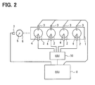
- FIG. 2 is a diagram showing an engine system
- FIG. 3 is a graph showing time variation of a voltage of a sensor signal
- FIG. 4 is a flowchart showing a cylinder inner pressure detection process
- FIG. 5 is a circuit diagram showing a differential amplifier circuit according to a second embodiment.
- an engine 1 as an internal combustion engine is a four stroke engine having four cylinders 2 , which are first to fourth cylinders.
- One combustion cycle includes first to fourth cycles, i.e., an intake stroke, a compression stroke, a power stroke (i.e., a combustion stroke) and an exhaust stroke.
- the cycle has a 720-degree CA cycle.
- Each stroke at one cylinder is performed with a deviation of 180-degree CA (crank angle) from an adjacent cylinder.
- 180-degree CA crank angle
- one stroke of one cylinder starts with a crank angle different from adjacent cylinder by 180 degrees.
- Each cylinder 2 includes a cylinder block and a cylinder head. Each cylinder 2 further includes a piston accommodated therein. Further, the cylinder 2 has a combustion chamber disposed over the piston.
- a cylinder inner pressure sensor 3 is arranged on the cylinder head of each cylinder 2 . In the pressure sensor 3 , pressure of a combustion chamber as the cylinder inner pressure is applied to a Piezo-electric device (e.g., Piezo-electric resistor) via a diaphragm. An output voltage of the Piezo-electric device is amplified, and then, the Piezo-electric device outputs a sensor signal. The voltage Vp of the sensor signal increases with the cylinder inner pressure.
- a Piezo-electric device e.g., Piezo-electric resistor
- An injector 4 for injecting fuel into the combustion chamber is arranged in the cylinder 2 .
- the piston is reciprocated.
- a crank shaft 5 as an output shaft of the engine rotates.
- a pulsar 6 having teeth disposed on an outer periphery of a body at predetermined intervals rotates together with the crank shaft 5 .
- a crank angle sensor 7 including an electro-magnetic pick-up unit faces the pulsar 7 .
- the sensor 7 outputs a crank angle signal having a pulse shape according to the rotation of the crank shaft 5 .
- the engine ECU 8 includes a micro computer 9 .
- the computer 9 executes a control program stored in a non-volatile memory.
- various sensor signals such as the crank angle signal and an acceleration opening degree signal are input unto the ECU 8 so that the ECU 8 obtains information about the driving conditions of the engine 1 .
- the ECU 8 executes a fuel supply control.
- the ECU 8 calculates a starting timing of injection of the fuel and an injection timing with respect to a fuel injection cylinder so that the ECU 8 executes a fuel injection control.
- the ECU 8 outputs an injection signal to an EDU (i.e., electronic driving unit) 10 so that the ECU 8 controls an injector 4 .
- EDU i.e., electronic driving unit
- FIG. 1 shows a cylinder inner pressure detection circuit 11 in the ECU 8 .
- a cylinder inner pressure detection circuit 11 includes the micro computer 9 , a crank angle signal input circuit 12 and a cylinder inner pressure signal input circuit 13 .
- the cylinder inner pressure signal input circuit 13 is arranged at each cylinder inner pressure sensor 3 .
- FIG. 1 shows only one circuit 13 .
- the detection circuit 11 , the sensor 3 and the crank angle sensor 7 are energized with a common power source voltage Vcc such as 5 volts so that they function.
- the crank angle signal input circuit 12 as a crank angle detection device detects a crank angle and a rotation speed based on the crank angle signal, which is output from a crank angle sensor 7 .
- the micro computer 9 as a controller includes a CPU 14 , a RAM 15 , a ROM 16 , an A/D converter circuit 17 and an input/output port.
- the ROM 16 as a non volatile memory stores the above described control program, various data used for the fuel supply control and the fuel injection control, and reference voltages Vr 1 , Vr 2 and Vr 3 .
- the A/D converter circuit 17 includes an A/D converter 18 and a multiplexer 19 so that the A/D converter circuit 17 provides multiple channels.
- the A/D converter 18 has a sample hold circuit.
- the input circuit 13 at each cylinder uses two channels. Thus, when the engine includes four cylinders, eight channels are used.
- the sensor signal output from the inner pressure sensor 3 is converted in an A/D conversion manner with using first and second channels CH 1 , CH 2 .
- the first channel CH 1 is provided by a first A/D converter circuit 17 a
- the second channel CH 2 is provided by a second A/D converter circuit 17 b .
- Other channels are not shown in FIG. 1 .
- the input range of the A/D converter circuit 17 at each channel is from zero volt as a lower limit voltage to 5 volts as an upper limit voltage.
- the input circuit 13 includes a reference voltage output circuit 20 , a buffer circuit 21 , a differential amplifier circuit 22 and the like.
- the reference voltage output circuit 20 outputs a reference voltage Vr having a certain level, which is selected among three different reference voltages Vr 1 , Vr 2 and Vr 3 having different levels based on a switching signal Sc.
- Each reference voltage Vr 1 , Vr 2 and Vr 3 is generated by dividing the power source voltage Vcc with multiple resistors 23 a to 23 d .
- the resistors 23 a - 23 d provide a voltage division circuit 23 .
- the selector switch 24 selects one of the reference voltages Vr 1 , Vr 2 and Vr 3 in accordance with the switching signal Sc.
- Selected reference voltage Vr is output via an operational amplifier 25 , which provides a voltage follower.
- the sensor signal output from the cylinder inner pressure sensor 3 has a frequency component in a range between 10 HZ and 120 Hz.
- unwanted components such as a noise of the sensor signal is removed by a low pass filter 26 , which includes a resistor 26 a and a capacitor 26 b .
- the sensor signal is input into the buffer circuit 21 .
- An output voltage Vq of the buffer circuit 21 is input into the differential amplifier circuit 22 and the second A/D converter circuit 17 b.
- the gain of the buffer circuit 21 is set such that the voltage Vq is disposed in an input range of the second A/D converter circuit 17 b in a whole region of the combustion cycle of the engine 1 , i.e., in a whole region of 720 degrees CA.
- the gain is set to be one. Accordingly, the sensor signal having the voltage Vp is input into the second A/D converter circuit 17 b without amplifying and shifting a level of the sensor signal.
- An input section of the second A/D converter circuit 17 b includes a low pass filter 27 , which includes a resistor 27 a and a capacitor 27 b .
- the capacitor 27 b reduces a sampling error, which is generated by a charge distribution between the capacitor 27 b and a capacitor for holding a sample in the A/D converter 18 .
- the differential amplifier circuit 22 corresponds to a level shift circuit.
- the circuit 22 includes an operational amplifier 22 a and resistors 22 b - 22 e .
- the resistance of each of the resistors 22 b and 22 d is defined as a resistance R 1
- the resistance of each of the resistors 22 c and 22 e is defined as a resistance R 2 .
- the output voltage Vs of the differential amplifier circuit 22 is obtained by the following equation F 1 .
- Vs R 2 /R 1( Vq ⁇ Vr ) F1
- the differential amplifier circuit 22 shifts a level of the sensor signal having the voltage of Vq output from the buffer circuit 21 by the reference voltage Vr in a direction of the signal voltage corresponding to the low pressure side of the inner pressure. Specifically, the circuit 22 reduces the voltage Vq of the sensor signal by the reference voltage Vr. Then, the circuit 22 amplifies (R 2 /R 1 ) times the reduced voltage Vq, and inputs the amplified voltage Vq to the first A/D converter circuit 17 a .
- the input unit for inputting into the first A/D converter circuit 17 a includes a diode 28 and a capacitor 29 .
- the capacitor 29 reduces a sampling error caused by the charge division between the capacitor 29 and a capacitor for holding a sample in the A/D converter 18 , similar to the capacitor 27 b.
- FIG. 3 shows time variation of the voltage Vp of the sensor signal in two combustion cycles.
- the cylinder inner pressure rapidly increases at the compression stroke. Then, after a compression top dead center (compression TDC), the inner pressure represents the maximum value in the power stroke. Then, the inner pressure rapidly reduces when the cycle proceeds from the power stroke to the exhaust stroke. The inner pressure reaches the minimum value when the cycle proceeds from the exhaust stroke to the intake stroke.
- the voltage Vp of the sensor signal also varies in accordance with the inner pressure. However, the offset voltage Vpo may change (i.e., drift) according to the temperature change and/or the pressure change.
- the offset voltage Vpo is the voltage Vp of the sensor signal while the inner pressure reduces to the minimum value. Specifically, the offset voltage Vpo is the voltage Vp of the sensor signal in a period from the ATDC of 300 degrees CA in one cycle to the BTDC of 150 degrees CA in a next cycle, the period in which the inner pressure is minimum. Between the one cycle and the next cycle in FIG. 3 , the offset voltage Vpo drifts by ⁇ Vd as an offset drift. Specifically, the offset voltage Vpo in the next cycle is different by ⁇ Vd from the one cycle.
- the voltage Vp of the sensor signal in a whole of the combustion cycle is disposed within an input range of the second A/D converter circuit 17 b between 0 volt and 5 volts.
- the gain of the differential amplifier circuit 22 shown in equations F 1 and F 2 is set to be larger than one.
- the maximum variation width of the voltage Vs of the sensor signal other than the drift, which is amplified in each combustion cycle is substantially equal to the input range width (e.g., 5 volts) of the first A/D converter circuit 17 a although the maximum variation width may be slightly different from the input range width by a little allowance width.
- the input range width e.g., 5 volts
- the sensor signal is defined as the voltage Vp, which is a value before amplifying.
- Vp the voltage
- the input range of the first A/D converter circuit 17 a relatively narrowed with respect to the sensor signal because of the amplification effect of the differential amplifier circuit 22 is shown as a chain double-dashed line.
- the level shift is performed with using the reference voltage Vr 3 , which is the nearest value of the offset voltage Vpo 1 and has the level on the signal potential side (i.e., zero volt side) corresponding to the low pressure side of the inner pressure from the offset voltage Vpo 1 .
- the level shift is performed with using the reference voltage Vr 2 , which is the nearest value of the offset voltage Vpo 2 and has the level on the signal potential side (i.e., zero volt side) corresponding to the low pressure side of the inner pressure from the offset voltage Vpo 2 .
- FIG. 4 shows a flowchart of the inner pressure detection process, which is executed repeatedly by the micro computer 9 .
- the A/D converter circuit 17 executes the A/D conversion with switching the multiplexer 19 so that the A/D conversion in each channel including the first A/D converter circuit 17 a and the second A/D converter circuit 17 b is sequentially executed.
- the digital conversion value output from each channel of the A/D converter circuit 17 is stored in the RAM 15 .
- the micro computer 9 detects the offset voltage Vpo in a period between the ATDC of 300 degrees CA in one cycle and the BTDC of 150 degrees CA in the next cycle.
- step S 1 it is determined whether the ATDC of 300 degrees CA is detected. Specifically, in step S 1 , until the ATDC of 300 degrees CA as the detection point is detected, the process is in a standby mode.
- step S 2 When it is determined that the ATDC of 300 degrees CA is detected, i.e., when the determination of step S 1 is “YES,” in step S 2 , the offset voltage Vpo is detected in step S 2 according to the digital conversion value output from the second A/D converter circuit 17 b .
- the micro computer 9 selects one of Vr 1 to Vr 3 as the reference voltage Vr, which is the nearest value of the offset voltage Vpo on the signal potential side corresponding to the low pressure side of the inner pressure from the offset voltage Vpo. Then, in step S 4 , the switching signal Sc for switching to the reference voltage Vr with using the reference voltage output circuit 20 .
- step S 4 the micro computer 9 outputs the switching signal Sc at a certain crank angle.
- the certain crank angle is prior to the crank angle, at which the detection of the inner pressure is actually necessitated, by at least an angle corresponding to a stabilization time Ts.
- the crank angle, at which the detection of the inner pressure is actually necessitated is for example, the BTDC 150 degrees CA.
- step S 5 the process waits for passing at least the stabilization time Ts.
- the micro computer 9 does not utilize the digital conversion value output from the first A/D converter circuit 17 a until the predetermined stabilization time Ts has elapsed since the switching signal Sc is output. Thus, it is restricted from erroneous detection of the inner pressure with using the digital conversion value before the operation is stabilized after the reference voltage Vr is switched.
- step S 6 the micro computer 9 inputs the digital conversion value from the first A/D converter circuit 17 a and the second A/D converter circuit 17 b . Since the reference voltage Vr is appropriately selected in step S 3 , the voltage Vs of the sensor signal to be output from the differential amplifier circuit 22 should be disposed within the input range of the first A/D converter circuit 17 a . Although normally the inner pressure sensor 3 outputs the voltage Vp in a range between 1 volt and 4 volts, the sensor 3 may output the voltage Vp out of the range. Further, the voltage Vs may exceed the input range of the first A/D converter circuit 17 a when the rapid offset drift occurs, or when the step width among the reference voltages Vr 1 to Vr 3 is very large.
- step S 7 the micro computer 9 executes calculation with reference to the digital conversion value output from the second A/D conversion circuit 17 b and the reference voltage Vr selected according to the switching signal Sc. Further, the microcomputer 9 determines whether the voltage Vs is disposed in the input range of the first A/D converter circuit 17 a in step S 7 . Here, when the micro computer 9 determines that the voltage Vs is disposed in the input range, i.e., when the determination of step S 7 is “YES,” it goes to step S 8 . In step S 8 , the micro computer 9 calculates the inner pressure based on the digital conversion value having the high resolution output from the first A/D converter circuit 17 a .
- step S 9 the micro computer 9 calculates the inner pressure based on the digital conversion value output from the second A/D converter circuit 17 b .
- steps S 7 and S 9 may be skipped.
- step S 10 the micro computer 9 determines whether the timing, at which the detection value of the inner pressure is needed, has come.
- the timing, at which the detection value of the inner pressure is needed may be the ATDC 180 degrees CA, for example.
- the computer 9 determines whether the cycle passes through the ATDC 180 degrees CA. Until the cycle passes through the ATDC 180 degrees CA, the computer repeats steps S 6 to S 9 . After the cycle passes through the ATDC 180 degrees CA, it returns to step S 1 . Then, in order to detect the inner pressure of the next combustion cycle, the computer starts to execute the detection process for detecting the offset voltage Vpo.
- the micro computer 9 detects the offset voltage Vpo of the sensor signal while the inner pressure is reduced.
- the computer 9 shifts the level of the sensor signal toward to the low pressure side by the reference voltage Vr corresponding to the offset voltage Vpo.
- the higher inner pressure can be detected according to the digital conversion value output from the first A/D converter circuit 17 a .
- the dynamic range of the first A/D converter circuit 17 a with respect to the sensor signal can be enlarged.
- the gain with respect to the sensor signal can be set higher, compared with a conventional detector.
- the resolution of the first A/D converter circuit 17 a is improved, so that the inner pressure is detected with high accuracy. The effects are obtained in a case where the offset drift occurs at the inner pressure sensor 3 and in a case where the gain of the sensor 3 as a sensing sensitivity factor is changed.
- the computer selects the reference voltage Vr, which is the nearest value of the offset voltage Vpo on the signal potential side corresponding to the low pressure side of the inner pressure from the offset voltage Vpo, and then, executes the level shift operation.
- the dynamic range can be broadened with using one of the reference voltages Vr 1 to Vr 3 , which are capable of being output from the reference voltage output circuit 20 .
- the cylinder inner pressure is detected with high accuracy.
- the differential amplifier circuit 22 executes both of the level shift operation and the amplification operation at the same time. Thus, the number of elements of the detector is reduced, and further, the manufacturing cost of the detector is reduced.
- the gain is set such that the maximum variation width of the output voltage Vs of the differential amplifier circuit 22 approaches the input range width of the first A/D converter circuit 17 a . Accordingly, very high resolution is obtained.
- the cylinder inner pressure detection circuit 11 includes the second A/D converter circuit 17 b for setting the voltage Vp of the sensor signal in a whole of the combustion cycle within the input range.
- the micro computer 9 detects the offset voltage Vpo with using the digital conversion value output from the second A/D converter circuit 17 b .
- the computer 9 detects the offset voltage Vpo.
- the computer detects the inner pressure based on the digital conversion value output from the second A/D converter circuit 17 b .
- the inner pressure detection circuit 11 includes a crank angle signal input circuit 12 for detecting the crank angle based on the crank angle signal.
- the computer 9 determines the period, in which the inner pressure is minimum, based on the detected crank angle. Thus, the computer 9 can detect the offset voltage Vpo accurately.
- the micro computer 9 outputs the switching signal Sc of the reference voltage Vr at the certain crank angle.
- the certain crank angle is prior to the crank angle, at which it is necessary to detect the inner pressure, by at least an angle corresponding to the stabilization time Ts of the reference voltage output circuit 20 and the differential amplifier circuit 22 .
- the inner pressure is detected with high accuracy under a condition that the operation of both of the reference voltage output circuit 20 and the differential amplifier circuit 22 is stable.
- the inner pressure detection circuit 11 includes the differential amplifier circuit 22 and the reference voltage output circuit 20 in each cylinder 2 .
- characteristic variations of the cylinder inner pressure sensors 3 of the cylinders 2 are individually adjusted.
- each cylinder 2 includes the reference voltage output circuit 20 , the influence of the noise caused at a time when the reference voltage Vr is switched is improved (i.e., reduced).
- FIG. 5 shows the differential amplifier circuit 30 in the cylinder inner pressure detection circuit 11 .
- the differential amplifier circuit 30 corresponding to the level shift circuit includes an operational amplifier 30 a , resistors 30 b - 30 g and selector switches 30 h , 30 i .
- the selector switch 30 h switches between the resistor 30 b and the resistor 30 h .
- the selector switch 30 i switches between the resistor 30 e and the resistor 30 f .
- the switch 30 h in association with the switch 30 i executes the switching operation according to the gain switching signal Sg.
- the resistance of each of the resistors 30 b , 30 e is defined as R 11
- the resistance of each of the resistors 30 c , 30 f is defined as R 12
- the resistance of each of the resistors 30 d , 30 g is defined as R 21 .
- the output voltage Vs of the differential amplifier circuit 30 satisfies the following equations F 3 and F 4 .
- Vs R 21 /R 11( Vq ⁇ Vr ) F3
- Vs R 21 /R 12( Vq ⁇ Vr ) F4
- the computer 9 detects the combustion conditions based on the sensor signals output from various sensors including the inner pressure sensor 3 .
- the computer 9 operates the selector switches 30 h , 30 i in such a manner that the maximum variation width of the voltage Vs under the combustion conditions is equal to or smaller than the input range width of the second A/D converter circuit 17 b and the maximum variation width approaches the input range width.
- the appropriately dynamic range with respect to the sensor signal is secured, and further, the resolution is improved.
- the micro computer 9 sets the input range in a range between 0 volt and 5 volts when the computer 9 executes the determination process in step S 7 for determining whether the voltage Vs is disposed in the input range of the first A/D converter circuit 17 a .
- the computer 9 may set the input range in a narrower range. For example, the upper limit of 5 volts of the input range of the first A/D converter circuit 17 a may be reduced, to an upper threshold voltage such as 4.5 volts. Further, the lower limit of 0 volt of the input range of the first A/D converter circuit 17 a may be increased to a lower threshold voltage such as 0.5 volt. In this case, the computer 9 determines whether the voltage Vs of the amplified sensor signal is disposed in the input range between the upper threshold voltage and the lower threshold voltage.
- the A/D conversion error near the upper limit voltage of the input range may be larger than the error in a middle of the input range.
- the A/D conversion error near the lower limit voltage of the input range e.g., in a range between 0 volt and 0.5 volts
- the A/D conversion error is reduced, so that the inner pressure is detected with high accuracy.
- step S 5 the computer 9 waits for the predetermined stabilization time Ts after the switching signal Sc is output so that the operation of the switching of the reference voltage Vr is stabilized.
- the computer 9 may determine that the operation of the switching of the reference voltage Vr is completed when the difference between the inner pressure detected by the digital conversion value output from the first A/D converter circuit 17 a and the inner pressure detected by the digital conversion value output from the second A/D converter circuit 17 b is equal to or smaller than a predetermined threshold value for the switching completion determination.
- the computer 9 may determine that the operation of the switching of the reference voltage Vr is completed after the earlier of: or the later of: the time when the stabilization time Ts has elapsed; or the time when the difference of the inner pressure is equal to or smaller than the predetermined threshold value. Thus, waste of time is minimized. Further, the computer 9 does not detect the inner pressure before the operation of the switching of the reference voltage Vr is completed, i.e., before the operation is stabilized.
- the first and second A/D converter circuits 17 a , 17 b execute the A/D conversion concurrently.
- the micro computer 9 may determine at any time in the combustion cycle whether an erroneous situation occurs when the difference between the inner pressure detected according to the digital conversion value output from the first A/D conversion circuit 17 a and the inner pressure detected according to the digital conversion value output from the second A/D conversion circuit 17 b is equal to or larger than an error determination threshold.
- the computer 9 detects the error occurring at least one of the first and second A/D converter circuits 17 a , 17 b . The reliability of the inner pressure detection circuit 11 is improved.
- the offset voltage Vpo is detected according to the digital conversion value output from the second A/D converter circuit 17 b .
- the offset voltage Vpo may be detected according to the digital conversion value output from the first A/D converter circuit 17 a .
- the gain may be set such that the voltage Vs of the sensor signal is disposed in the input range of the first A/D converter circuit 17 a .
- the offset voltage Vpo may be detected after the reference voltage Vr is changed so that the voltage Vs is disposed in the input range of the first A/D converter circuit 17 a . In this case, it is not necessary to equip the second A/D converter circuit 17 b in the detector.
- the second A/D converter circuit 17 b may execute the A/D conversion after the detector shifts the level of the sensor signal by a predetermined reference voltage.
- a buffer circuit 21 may be arranged in the first and second A/D converter circuits 17 a , 17 b , individually so that the gain of each buffer circuit 21 is set.
- the A/D converter circuit 17 may include an A/D converter 18 at each channel instead the A/D converter circuit 17 includes the multiplexer 19 .
- the level shift circuit may be a circuit other than the differential amplifier circuit 22 . As long as the level shift circuit performs the level shift function, the level shift circuit may be any circuit. In this case, the amplification function may be performed by other amplifier circuits such as the buffer circuit 21 .
- the reference voltage output circuit 20 can output three reference voltages Vr 1 to Vr 3 .
- the circuit 20 may output two, four or more reference voltages.
- the circuit 20 may output the reference voltage Vr, which is continuously variable (i.e., an analog value), and therefore, not the discrete voltage.
- the reference voltage Vr to be selected by the reference voltage output circuit 20 has the level on the signal potential side corresponding to the low pressure side of the inner pressure from the offset voltage Vpo, the reference voltage Vr may be any voltage. Thus, it is not necessary to select the reference voltage Vr, which is the nearest voltage of the offset voltage Vpo.
- the inner pressure detection circuit 11 includes the reference voltage detection circuit 20 at each cylinder 2 .
- a common reference voltage output circuit 20 may be arranged for multiple cylinders 2 .
- an cylinder inner pressure detector for detecting a cylinder inner pressure of an internal combustion engine by converting a sensor signal from an analog signal to a digital signal, the sensor signal being output from a cylinder inner pressure sensor in accordance with the cylinder inner pressure
- the cylinder inner pressure detector includes: a reference voltage output circuit for outputting a reference voltage having a level, which is selected among a plurality of levels according to a switching signal; a level shift circuit for shifting a level of the sensor signal by a selected level of the reference voltage toward a signal potential side corresponding to a low pressure side of the cylinder inner pressure and for outputting a shifted sensor signal; a first A/D converter circuit for receiving the shifted sensor signal from the level shift circuit and for converting the shifted sensor signal from an analog signal to a digital signal; and a controller for outputting the switching signal, which provides the reference voltage to be selected by the reference voltage output circuit in such a manner that the reference voltage has the level disposed on the signal potential side corresponding to the low pressure
- the sensor signal corresponding to a high pressure period can be disposed in the input range of the first A/D converter circuit.
- an unused range of the input range attributed to the offset drift is reduced, so that an effective variable signal width as a dynamic range of the A/D converter circuit with respect to the sensor signal is widely secured.
- the gain with respect to the sensor signal can be set higher than a conventional art, so that the resolution of the first A/D converter circuit is improved, and the inner pressure is detected with high accuracy.
- the cylinder inner pressure detector may further include: a second A/D converter circuit for receiving the sensor signal from the cylinder inner pressure sensor and for converting the sensor signal from an analog signal to a digital signal.
- the controller detects the offset voltage based on the digital signal output from the second A/D converter circuit when the cylinder inner pressure is minimum.
- the second A/D converter circuit executes the A/D conversion with shifting the level according to a constant reference voltage or without shifting the level of the sensor signal even if the offset of the sensor signal is varied.
- the reference voltage output circuit can select the reference voltage surely.
- a gain of the sensor signal to be input into the second A/D converter circuit may be set in such a manner that the voltage of the sensor signal is disposed in an input range of the second A/D converter circuit.
- the second A/D converter circuit can detect the inner pressure including the offset voltage without changing the gain of the sensor signal.
- the sensor signal exceeds the input range of the first A/D converter circuit when the offset voltage is drifted, the inner pressure is detected accurately by the second A/D converter circuit instead of the first A/D converter circuit.
- the cylinder inner pressure detector may further include: a crank angle detector for detecting a crank angle based on a crank angle signal, which is output from a crank angle sensor.
- the crank angle sensor is disposed in the internal combustion engine, and the controller detects the offset voltage based on the digital signal output from the second A/D converter circuit when the crank angle is separated from a compression top dead center by a predetermined angle or more.
- the inner pressure represents the maximum value in the power stroke around the compression top dead center. Then, the inner pressure reduces when the cycle proceeds from the power stroke to the exhaust stroke. The inner pressure increases again when the cycle proceeds from the intake stroke to the compression stroke.
- the inner pressure reaches the minimum value when the crank angle is separated from a compression top dead center by a predetermined angle or more.
- the inner pressure reaches the minimum value in a crank angle range between the exhaust stroke and the intake stroke.
- the controller outputs the switching signal at a crank angle, which is prior to the certain crank angle by at least an angle corresponding to a stabilization time of the reference voltage.
- the inner pressure is detected with high accuracy with using the stable reference voltage during the certain crank angle range at which the detection of the cylinder inner pressure is necessitated.
- the switching signal may be output at a certain crank angle, which corresponds to the stabilization time of the level shift circuit in addition to the stabilization time of the reference voltage.
- the controller may utilize the digital signal from the first A/D converter circuit after a predetermined stabilization time has elapsed since the switching signal is output.
- detection of the inner pressure with using the digital signal before the switching operation of the reference voltage is stabilized is prevented.
- the detection of the cylinder inner pressure is necessitated includes a reference voltage output operation executed by the reference voltage output circuit and an operation of the level shift circuit based on a new reference voltage. Further, the determination error of the erroneous situation is prevented since the digital signal before the switching operation of the reference voltage is stabilized is used.
- the level shift circuit may include a differential amplifier circuit, which shifts the level of the sensor signal by the reference voltage, and amplifies the shifted sensor signal with a predetermined gain.
- the differential amplifier circuit can shift the level of the sensor signal and set the gain, and therefore, the number of elements in the detector is reduced, and the manufacturing cost of the detector is also reduced.
- the A/D conversion is performed after the sensor signal is amplified by the differential amplifier circuit, the dynamic range of the sensor signal is appropriately secured even if the variation width of the inner pressure is small, so that the amplitude of the sensor signal is small. Accordingly, the resolution of the detector is improved.
Landscapes
- Chemical & Material Sciences (AREA)
- Engineering & Computer Science (AREA)
- Combustion & Propulsion (AREA)
- Physics & Mathematics (AREA)
- General Physics & Mathematics (AREA)
- Measuring Fluid Pressure (AREA)
- Combined Controls Of Internal Combustion Engines (AREA)
Applications Claiming Priority (2)
| Application Number | Priority Date | Filing Date | Title |
|---|---|---|---|
| JP2011-175911 | 2011-08-11 | ||
| JP2011175911A JP5413422B2 (ja) | 2011-08-11 | 2011-08-11 | 内燃機関の筒内圧検出装置 |
Publications (2)
| Publication Number | Publication Date |
|---|---|
| US20130036803A1 US20130036803A1 (en) | 2013-02-14 |
| US8733157B2 true US8733157B2 (en) | 2014-05-27 |
Family
ID=47676655
Family Applications (1)
| Application Number | Title | Priority Date | Filing Date |
|---|---|---|---|
| US13/490,730 Active 2032-11-24 US8733157B2 (en) | 2011-08-11 | 2012-06-07 | Cylinder inner pressure detector for internal combustion engine |
Country Status (2)
| Country | Link |
|---|---|
| US (1) | US8733157B2 (ja) |
| JP (1) | JP5413422B2 (ja) |
Cited By (1)
| Publication number | Priority date | Publication date | Assignee | Title |
|---|---|---|---|---|
| US20150323406A1 (en) * | 2012-10-05 | 2015-11-12 | Continental Automotive France | Measurement amplifying circuit for piezoelectric sensor positioned in an internal combustion engine |
Families Citing this family (7)
| Publication number | Priority date | Publication date | Assignee | Title |
|---|---|---|---|---|
| JP5579787B2 (ja) * | 2012-06-19 | 2014-08-27 | 本田技研工業株式会社 | 内燃機関の制御装置 |
| US9080920B2 (en) | 2013-03-05 | 2015-07-14 | Measurement Specialties, Inc. | System and method for multiplexed and buffered miniaturized sensor arrays |
| JP6079581B2 (ja) * | 2013-11-22 | 2017-02-15 | トヨタ自動車株式会社 | 筒内圧検出装置 |
| JP6249866B2 (ja) * | 2014-04-10 | 2017-12-20 | 本田技研工業株式会社 | 内燃機関の燃料噴射装置 |
| JP6398780B2 (ja) * | 2015-02-23 | 2018-10-03 | 株式会社デンソー | 内燃機関用電子制御装置 |
| WO2016208422A1 (ja) * | 2015-06-22 | 2016-12-29 | アルプス電気株式会社 | 圧力測定装置、圧力測定方法及びプログラム |
| EP3849485A4 (en) | 2018-09-12 | 2022-06-15 | Massachusetts Institute of Technology | SYSTEM AND METHOD FOR MEDICAL MONITORING WIRELESS DETECTION |
Citations (10)
| Publication number | Priority date | Publication date | Assignee | Title |
|---|---|---|---|---|
| JPH07280686A (ja) | 1994-04-07 | 1995-10-27 | Unisia Jecs Corp | 内燃機関の筒内圧検出装置 |
| JP2002242750A (ja) | 2001-02-14 | 2002-08-28 | Honda Motor Co Ltd | 内燃機関の筒内圧検出装置 |
| US20060032291A1 (en) * | 2003-04-21 | 2006-02-16 | Fuji Jukogyo Kabushiki Kaisha | Combustion-pressure-data acquisition system of multi-cylinder engine |
| JP2008216223A (ja) | 2007-03-08 | 2008-09-18 | Ngk Spark Plug Co Ltd | 筒内圧センサの出力補正装置及びこれを備えた筒内圧検出装置 |
| JP2008297952A (ja) | 2007-05-30 | 2008-12-11 | Denso Corp | 筒内圧センサの出力特性検出装置及び出力補正装置 |
| JP2009229328A (ja) | 2008-03-25 | 2009-10-08 | Ngk Spark Plug Co Ltd | 筒内圧センサの出力補正装置及びこれを備えた筒内圧検出装置 |
| JP2010196556A (ja) | 2009-02-24 | 2010-09-09 | Denso Corp | 発熱量算出装置、内燃機関の制御装置及びインジェクタの異常検出装置 |
| US20110088459A1 (en) * | 2009-10-16 | 2011-04-21 | Gm Global Technology Operations, Inc. | Method for determining an in-cylinder pressure curve of a multi-cylinder engine |
| US20120303238A1 (en) * | 2011-05-23 | 2012-11-29 | GM Global Technology Operations LLC | Cylinder pressure sensor compensation systems and methods |
| US20130179052A1 (en) * | 2012-01-11 | 2013-07-11 | Denso Corporaiton | Sensor signal processing device |
Family Cites Families (7)
| Publication number | Priority date | Publication date | Assignee | Title |
|---|---|---|---|---|
| JPS616748U (ja) * | 1984-06-20 | 1986-01-16 | 日産自動車株式会社 | 内燃機関の燃焼室内圧力検出装置 |
| JPH02259438A (ja) * | 1989-03-30 | 1990-10-22 | Matsushita Electric Ind Co Ltd | 内燃機関の気筒内圧力の零点検出装置と気筒内圧力の補正装置 |
| JP2582160B2 (ja) * | 1989-07-20 | 1997-02-19 | 株式会社日立製作所 | センサ装置 |
| JP2000341126A (ja) * | 1999-05-26 | 2000-12-08 | Matsushita Electric Works Ltd | D/a変換回路およびそれを用いた圧力センサ回路 |
| JP2001182596A (ja) * | 1999-12-28 | 2001-07-06 | Mikuni Corp | 内燃機関の吸気圧力検出装置 |
| JP4321029B2 (ja) * | 2002-09-17 | 2009-08-26 | 株式会社豊田中央研究所 | 圧力センサ出力処理装置と圧力センサ装置 |
| JP2009229329A (ja) * | 2008-03-25 | 2009-10-08 | Ngk Spark Plug Co Ltd | 筒内圧センサの出力補正装置及びこれを備えた筒内圧検出装置 |
-
2011
- 2011-08-11 JP JP2011175911A patent/JP5413422B2/ja active Active
-
2012
- 2012-06-07 US US13/490,730 patent/US8733157B2/en active Active
Patent Citations (11)
| Publication number | Priority date | Publication date | Assignee | Title |
|---|---|---|---|---|
| JPH07280686A (ja) | 1994-04-07 | 1995-10-27 | Unisia Jecs Corp | 内燃機関の筒内圧検出装置 |
| JP2002242750A (ja) | 2001-02-14 | 2002-08-28 | Honda Motor Co Ltd | 内燃機関の筒内圧検出装置 |
| US20060032291A1 (en) * | 2003-04-21 | 2006-02-16 | Fuji Jukogyo Kabushiki Kaisha | Combustion-pressure-data acquisition system of multi-cylinder engine |
| JP2008216223A (ja) | 2007-03-08 | 2008-09-18 | Ngk Spark Plug Co Ltd | 筒内圧センサの出力補正装置及びこれを備えた筒内圧検出装置 |
| JP2008297952A (ja) | 2007-05-30 | 2008-12-11 | Denso Corp | 筒内圧センサの出力特性検出装置及び出力補正装置 |
| JP2009229328A (ja) | 2008-03-25 | 2009-10-08 | Ngk Spark Plug Co Ltd | 筒内圧センサの出力補正装置及びこれを備えた筒内圧検出装置 |
| JP2010196556A (ja) | 2009-02-24 | 2010-09-09 | Denso Corp | 発熱量算出装置、内燃機関の制御装置及びインジェクタの異常検出装置 |
| US20110088459A1 (en) * | 2009-10-16 | 2011-04-21 | Gm Global Technology Operations, Inc. | Method for determining an in-cylinder pressure curve of a multi-cylinder engine |
| US20120303238A1 (en) * | 2011-05-23 | 2012-11-29 | GM Global Technology Operations LLC | Cylinder pressure sensor compensation systems and methods |
| US8600644B2 (en) * | 2011-05-23 | 2013-12-03 | GM Global Technology Operations LLC | Cylinder pressure sensor compensation systems and methods |
| US20130179052A1 (en) * | 2012-01-11 | 2013-07-11 | Denso Corporaiton | Sensor signal processing device |
Cited By (2)
| Publication number | Priority date | Publication date | Assignee | Title |
|---|---|---|---|---|
| US20150323406A1 (en) * | 2012-10-05 | 2015-11-12 | Continental Automotive France | Measurement amplifying circuit for piezoelectric sensor positioned in an internal combustion engine |
| US9658127B2 (en) * | 2012-10-05 | 2017-05-23 | Contintental Automotive France | Measurement amplifying circuit for piezoelectric sensor positioned in an internal combustion engine |
Also Published As
| Publication number | Publication date |
|---|---|
| JP2013040777A (ja) | 2013-02-28 |
| JP5413422B2 (ja) | 2014-02-12 |
| US20130036803A1 (en) | 2013-02-14 |
Similar Documents
| Publication | Publication Date | Title |
|---|---|---|
| US8733157B2 (en) | Cylinder inner pressure detector for internal combustion engine | |
| US8342011B2 (en) | Method for determining a value representative of the pressure in a combustion chamber of an internal combustion engine | |
| JP5796561B2 (ja) | 車載用電子制御装置 | |
| US8239116B2 (en) | Method and apparatus for generating injection signals for an injection system of an internal combustion engine | |
| US7757545B2 (en) | Device and method for determining trouble of cylinder pressure sensor | |
| CN105545508B (zh) | 用于空燃比控制和检测汽缸不平衡的方法和系统 | |
| US7909018B2 (en) | Control for determining a firing timing of an internal-combustion engine | |
| US8413495B2 (en) | Apparatus for correcting output of cylinder internal pressure sensor, and cylinder internal pressure detection apparatus including the same | |
| US20130338906A1 (en) | Control apparatus for internal combustion engine, method of controlling internal combustion engine, and computer-readable storage medium | |
| US9523621B2 (en) | Electronic control system | |
| JP2005291182A (ja) | 失火検出装置 | |
| US7881855B2 (en) | Method for metering fuel into combustion chambers of an internal combustion engine | |
| US5027775A (en) | Apparatus for controlling combustion condition | |
| US8418539B2 (en) | Method and circuit for processing a signal supplied by a piezoelectric sensor, and pressure-measuring device for piston engine | |
| US10309854B2 (en) | Method for processing a signal of a pressure measuring device inside an internal combustion engine | |
| JP4094475B2 (ja) | 多気筒エンジンの燃焼圧データ収集システム | |
| KR101858295B1 (ko) | 자동차의 연료 조절 시스템의 보정 방법 및 그 장치 | |
| JP2013147948A (ja) | 内燃機関の制御装置 | |
| US6915780B2 (en) | Combustion pressure data collection system for multi-cylinder engine | |
| KR102431892B1 (ko) | 전압 람다 특성 곡선의 적어도 일부에서 전압 오프셋을 검출하는 방법 | |
| FI113494B (fi) | Menetelmä mäntämoottorin nakutuksen tunnistusjärjestelmän asettamiseksi | |
| US7185637B1 (en) | Fuel injection control method and fuel injection control apparatus for engine | |
| JP5737205B2 (ja) | 筒内圧センサの異常診断装置 | |
| JP2020056367A (ja) | 内燃機関の燃焼状態検出装置および燃焼状態検出方法 | |
| JP4294463B2 (ja) | 内燃機関の筒内圧検出装置 |
Legal Events
| Date | Code | Title | Description |
|---|---|---|---|
| AS | Assignment |
Owner name: DENSO CORPORATION, JAPAN Free format text: ASSIGNMENT OF ASSIGNORS INTEREST;ASSIGNORS:ITOU, AKITO;KAWAKAMI, DAISUKE;REEL/FRAME:028335/0244 Effective date: 20120509 |
|
| FEPP | Fee payment procedure |
Free format text: PAYOR NUMBER ASSIGNED (ORIGINAL EVENT CODE: ASPN); ENTITY STATUS OF PATENT OWNER: LARGE ENTITY |
|
| STCF | Information on status: patent grant |
Free format text: PATENTED CASE |
|
| MAFP | Maintenance fee payment |
Free format text: PAYMENT OF MAINTENANCE FEE, 4TH YEAR, LARGE ENTITY (ORIGINAL EVENT CODE: M1551) Year of fee payment: 4 |
|
| MAFP | Maintenance fee payment |
Free format text: PAYMENT OF MAINTENANCE FEE, 8TH YEAR, LARGE ENTITY (ORIGINAL EVENT CODE: M1552); ENTITY STATUS OF PATENT OWNER: LARGE ENTITY Year of fee payment: 8 |