US8433224B2 - Development device, process cartridge including same, and image forming apparatus including same - Google Patents
Development device, process cartridge including same, and image forming apparatus including same Download PDFInfo
- Publication number
- US8433224B2 US8433224B2 US12/952,519 US95251910A US8433224B2 US 8433224 B2 US8433224 B2 US 8433224B2 US 95251910 A US95251910 A US 95251910A US 8433224 B2 US8433224 B2 US 8433224B2
- Authority
- US
- United States
- Prior art keywords
- developer
- compartment
- supply
- supply compartment
- end portion
- Prior art date
- Legal status (The legal status is an assumption and is not a legal conclusion. Google has not performed a legal analysis and makes no representation as to the accuracy of the status listed.)
- Expired - Fee Related, expires
Links
Images


Classifications
-
- G—PHYSICS
- G03—PHOTOGRAPHY; CINEMATOGRAPHY; ANALOGOUS TECHNIQUES USING WAVES OTHER THAN OPTICAL WAVES; ELECTROGRAPHY; HOLOGRAPHY
- G03G—ELECTROGRAPHY; ELECTROPHOTOGRAPHY; MAGNETOGRAPHY
- G03G15/00—Apparatus for electrographic processes using a charge pattern
- G03G15/06—Apparatus for electrographic processes using a charge pattern for developing
- G03G15/08—Apparatus for electrographic processes using a charge pattern for developing using a solid developer, e.g. powder developer
- G03G15/0822—Arrangements for preparing, mixing, supplying or dispensing developer
- G03G15/0844—Arrangements for purging used developer from the developing unit
-
- G—PHYSICS
- G03—PHOTOGRAPHY; CINEMATOGRAPHY; ANALOGOUS TECHNIQUES USING WAVES OTHER THAN OPTICAL WAVES; ELECTROGRAPHY; HOLOGRAPHY
- G03G—ELECTROGRAPHY; ELECTROPHOTOGRAPHY; MAGNETOGRAPHY
- G03G15/00—Apparatus for electrographic processes using a charge pattern
- G03G15/06—Apparatus for electrographic processes using a charge pattern for developing
- G03G15/08—Apparatus for electrographic processes using a charge pattern for developing using a solid developer, e.g. powder developer
- G03G15/0822—Arrangements for preparing, mixing, supplying or dispensing developer
- G03G15/0877—Arrangements for metering and dispensing developer from a developer cartridge into the development unit
-
- G—PHYSICS
- G03—PHOTOGRAPHY; CINEMATOGRAPHY; ANALOGOUS TECHNIQUES USING WAVES OTHER THAN OPTICAL WAVES; ELECTROGRAPHY; HOLOGRAPHY
- G03G—ELECTROGRAPHY; ELECTROPHOTOGRAPHY; MAGNETOGRAPHY
- G03G15/00—Apparatus for electrographic processes using a charge pattern
- G03G15/06—Apparatus for electrographic processes using a charge pattern for developing
- G03G15/08—Apparatus for electrographic processes using a charge pattern for developing using a solid developer, e.g. powder developer
- G03G15/0896—Arrangements or disposition of the complete developer unit or parts thereof not provided for by groups G03G15/08 - G03G15/0894
- G03G15/0898—Arrangements or disposition of the complete developer unit or parts thereof not provided for by groups G03G15/08 - G03G15/0894 for preventing toner scattering during operation, e.g. seals
-
- G—PHYSICS
- G03—PHOTOGRAPHY; CINEMATOGRAPHY; ANALOGOUS TECHNIQUES USING WAVES OTHER THAN OPTICAL WAVES; ELECTROGRAPHY; HOLOGRAPHY
- G03G—ELECTROGRAPHY; ELECTROPHOTOGRAPHY; MAGNETOGRAPHY
- G03G2215/00—Apparatus for electrophotographic processes
- G03G2215/08—Details of powder developing device not concerning the development directly
- G03G2215/0802—Arrangements for agitating or circulating developer material
- G03G2215/0816—Agitator type
- G03G2215/0819—Agitator type two or more agitators
- G03G2215/0822—Agitator type two or more agitators with wall or blade between agitators
Definitions
- the present invention generally relates to a development device using two-component developer consisting essentially of toner and carrier, a process cartridge including the same, and an image forming apparatus, such as a copier, a printer, a facsimile machine, or a multifunction machine having at least two of these capabilities, that includes the same.
- Two-component developer consisting essentially of toner and carrier is widely used in electrophotographic image forming apparatuses.
- Development devices using two-component developer typically include a developer container in which developer is contained, a rotary developer carrier such as a development roller, and a developer conveyance member such as a conveyance screw provided in the developer container.
- the developer conveyance member supplies developer to the developer carrier while transporting the developer through a developer supply compartment (i.e., a developer supply path) in the developer container in an axial direction of the developer carrier. Then, the developer carrier rotates and supplies the developer carried thereon to a development area facing an image carrier such as a photoconductor.
- the developer (hereinafter “used developer”) is collected either in the supply compartment (hereinafter “one-conveyance path method”) or a collection compartment separate from the supply compartment (hereinafter “supply-collection separation method).
- the one-conveyance path method has a drawback in that the concentration of toner in the developer in the supply compartment decreases downstream in a direction in which the developer is transported (hereinafter “developer conveyance direction”), and accordingly the concentration of toner in the developer supplied to the development area is uneven in the axial direction of the developer carrier. Such unevenness in toner concentration causes unevenness in image density of images formed on sheets of recording media and is undesirable. It is to be noted that hereinafter “downstream” and “upstream” as used in this specification means downstream and upstream in the developer conveyance direction unless otherwise specified.
- JP-2002-006599-A employs a supply-collection separation method in which used developer is collected in a collection compartment separate from the supply compartment (hereinafter “a supply-collection separation-type development device”).
- a supply-collection separation-type development device the concentration of toner in the developer in the supply compartment can be kept substantially constant in the developer conveyance direction.
- the concentration of toner in the developer supplied to the development area can be kept uniform in the axial direction of the developer carrier in the supply-collection separation-type development device, doing so makes it impossible to make such development devices compact.
- a vertical agitation arrangement shown in FIG. 17 is effective to make supply-collection separation-type development devices compact. More specifically, in a known supply-collection separation-type development device 3 Z shown in FIG. 17 , a supply compartment 301 SZ is disposed adjacent to and to one side of a developer carrier 302 Z (in FIG. 17 , in a lateral direction), and a collection compartment 301 CZ is disposed beneath the supply compartment 301 SZ. The collection compartment 301 CZ receives developer that has been transported to a downstream end portion of the supply compartment 301 SZ. In the development device 3 Z, developer is circulated in the direction indicated by outlined arrows A 1 and A 2 shown in FIG. 17 .
- the vertical agitation arrangement has a limitation regarding the location of a toner supply mechanism for supplying toner to the development device.
- developer is transported from the downstream end portion of the supply compartment 301 SZ to an upstream end portion of the collection compartment 301 CZ and transported from a downstream end portion of the collection compartment 301 CZ to an upstream end portion of the supply compartment 301 SZ, thus forming a developer circulation path.
- the development device 3 Z As the location of a toner supply port 310 Z through which toner is supplied to the developer circulating in the developer circulation path, a portion of the supply compartment 301 SZ facing the development area of the developer carrier 302 Z must be avoided. If toner is supplied to that portion, the toner just after supplied is likely to be carried by the developer carrier 302 Z to the development area. Since electrical charge of the toner just after supplied is insufficient, such toner can scatter on the backgrounds of output images or around the interior of the image forming apparatus if being used in image development.
- the toner supply position be positioned further from the upstream end portion of the supply compartment 301 SZ on the developer circulation path, outside the portion facing the development area of the developer carrier 302 Z.
- Such an arrangement can increase contact between the supplied toner and carrier particles in the developer, thus charging the supplied toner better, before the supplied toner reaches the upstream end portion of the supply compartment 301 SZ where the developer is carried onto the developer carrier 302 Z.
- toner is typically supplied to the collection compartment 301 CZ.
- to supply toner to the collection compartment 301 CZ in the vertical agitation arrangement in which the collection compartment 301 CZ is positioned beneath the supply compartment 301 SZ the arrangement is limited to the two arrangements described below.
- a toner supply route 350 is positioned on the side of the supply compartment 301 SZ, opposite the developer carrier 302 Z, and the toner supply port 310 Z, which is at a downstream end of the toner supply route 350 , is formed in a side wall of the collection compartment 301 CZ positioned beneath the supply compartment 301 SZ.
- This arrangement increases the size of the development device 3 Z in the lateral direction in FIG. 17 by a length corresponding to the width of the toner supply route 350 .
- FIG. 18 illustrates a second arrangement regarding the location of the toner supply route.
- a collection compartment 301 CZ′ is made longer than a supply compartment 301 SZ′ in the axial direction of a developer carrier 302 Z, and a toner supply port 310 Z is provided in the expanded portion of the collection compartment 301 CZ.
- This arrangement increases the size of the development device 3 Z 1 in the axial direction of the developer carrier 302 Z (in FIG. 18 , the lateral direction) by a length corresponding to the width of the toner supply port 310 Z.
- the development device becomes bulkier when toner is supplied to the collection compartment, which is not desirable.
- the inventors of the present embodiment recognize that there is a need for the development device to reduce scattering of toner in the background of output images and around the interior of the image forming apparatus without increasing the size of the device.
- one illustrative embodiment of the present invention provides a development device to develop a latent image formed on a latent image carrier with developer.
- the development device includes a developer carrier disposed facing the latent image carrier, to carry the developer by rotation to a development area facing the latent image carrier, a partition dividing an interior of the development device into at least a supply compartment and a collection compartment both facing the developer carrier and extending in an axial direction of the developer carrier, a developer circulation unit to circulate the developer in the development device, a toner supply port formed in an upper portion of a downstream end portion of the supply compartment in a developer conveyance direction in which the developer is circulated, positioned outside the development area in an axial direction of the developer carrier, and an airflow path limiter provided in the downstream end portion of the supply compartment and positioned closer to the development area than the toner supply port in the axial direction of the developer carrier, to restrict an airflow path above the developer in the downstream end portion of the supply compartment.
- the developer is supplied from the supply compartment to the developer carrier and is collected from the developer carrier to the collection compartment disposed lower than the supply compartment.
- a first communication port is formed in a bottom portion of the downstream end portion of the supply compartment, and a second communication port is formed in an upstream end portion of the supply compartment.
- the developer circulation unit includes a first developer conveyance member provided in the supply compartment, to supply the developer to the developer carrier while transporting the developer through the supply compartment in the axial direction of the developer carrier and a second developer conveyance member disposed in the collection compartment that faces the developer carrier, to transport in the axial direction of the developer carrier the developer separated from the developer carrier.
- Another illustrative embodiment provides a process cartridge that is removably installable in an image forming apparatus and including a latent image carrier on which a latent image is formed and the development device described above.
- Yet another illustrative embodiment provides an image forming apparatus including a latent image carrier on which a latent image is formed and the development device described above.
- FIG. 1 is a schematic diagram of an image forming apparatus according to an illustrative embodiment
- FIG. 2 in an end-on axial view of an image forming unit in the image forming apparatus shown in FIG. 1 ;
- FIG. 3 is a schematic cross-sectional view from a side of a development device according to an illustrative embodiment and illustrates flow of developer in the development device;
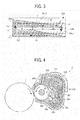
- FIG. 4 is an end-on axial view illustrating a downstream end portion of a collection compartment in the development device
- FIG. 5 illustrates distribution of magnetic flux density superimposed on a schematic end-on axial view of the development device
- FIG. 6 is a cross-sectional view from a side of a development roller included in the development device
- FIG. 7 is a perspective view illustrating a configuration of a developer circulation mechanism in the development device
- FIG. 8 is an exploded view of the developer circulation mechanism
- FIG. 9 is a schematic top view illustrating an interior of a supply compartment in the development device.
- FIG. 10 is a schematic end-on axial view of a portion of the supply compartment where a rib is provided
- FIG. 11 is a graph illustrating results of an experiment to evaluate scattering of toner in backgrounds on a photoconductor when the rib is provided (first condition) and is not provided (second condition);
- FIG. 12 is a schematic top view illustrating the interior of the supply compartment
- FIG. 13 is a schematic top view illustrating an interior of a supply compartment of a development device according to a first variation
- FIG. 14 is a schematic side view illustrating an interior of the development device according to the first variation
- FIG. 15 is a schematic top view illustrating an interior of a supply compartment in which location of a toner guide frame is different from that in FIGS. 13 and 14 ;
- FIG. 16 is a schematic end-on axial view illustrating a configuration of a developer circulation mechanism according to a second variation
- FIG. 17 is an end-on axial view of a development device of related art in which a developer collection compartment is disposed beneath a developer supply compartment and toner is supplied to the developer collection compartment;
- FIG. 18 is a cross-sectional view from a side of a development device of another related art in which a developer collection compartment is disposed beneath a developer supply compartment and toner is supplied to the developer collection compartment.
- FIG. 1 a multicolor image forming apparatus according to an illustrative embodiment of the present invention is described.
- FIG. 1 is a schematic diagram of an image forming apparatus according to the present embodiment.
- an image forming apparatus 100 is a tandem-type printer (hereinafter also “printer 100 ”) and includes multiple image forming units 17 K, 17 M, 17 Y, and 17 C arranged along a transport belt 15 that transports transfer sheets 8 (i.e., recording media).
- arrangement order of the image forming units 17 is not limited to that shown in FIG. 1 , and, for example, the image forming units 17 may be arranged in the order of magenta, cyan, yellow, and black with the image forming unit 17 K disposed extreme downstream in a direction in which the transfer sheet 8 is transported.
- Each image forming unit 17 includes a photoconductor 1 serving as a latent image carrier and forms black, magenta, yellow, or cyan images on the photoconductor 1 .
- each image forming unit 17 includes multiple components housed in a common unit casing and is configured as a process cartridge removably installable in a main body of the printer 100 although it is not necessary that those components are united as a single unit.
- the image forming units 17 K, 17 M, 17 Y, and 17 C have a similar configuration except for the color of toner used therein.
- the transport belt 15 is stretched around support rollers 18 and 19 .
- One of the rollers 18 and 19 is a driving roller and the other is a driven roller.
- the driving roller rotates, the transport belt 15 rotates in the direction indicated by an arrow shown in FIG. 1 .
- sheet cassettes 20 , 21 , and 22 are provided beneath the transport belt 15 , and a discharge tray 25 is provided on an upper surface of the main body of the printer 100 .
- the image forming unit 17 is described in further detail below.
- the photoconductor 1 rotates clockwise in FIG. 2 .
- a charging roller of a charging device 2 is provided above the photoconductor 1 .
- the charging device 2 in the present embodiment employs a contact-charging method, and the charging roller to which a charging bias is applied is disposed in contact with a circumferential surface of the photoconductor 1 , thereby charging the photoconductor 1 uniformly to a predetermined electrical potential.
- a noncontact method may be adopted.
- the circumferential surface of the photoconductor 1 thus charged uniformly by the charging device 2 receives an optical beam L (i.e., a writing light) emitted from an exposure unit 16 shown in FIG. 1 , and thus an electrostatic latent image is formed thereon.
- an optical beam L i.e., a writing light
- the charging device 2 and the exposure unit 16 together form a latent image forming unit.
- the electrostatic latent image formed on the photoconductor 1 is transported to a development area A (shown in FIG. 2 ) facing a development device 3 as the photoconductor 1 rotates.
- the development device 3 includes a casing 301 (shown in FIG. 2 ), serving as a developer container for containing two-component developer consisting essentially of toner and carrier and transports the developer to the development area A, in which toner in the developer adheres to the electrostatic latent image formed on the photoconductor 1 .
- the electrostatic latent image is developed into a toner image.
- the toner image is then transported to a portion facing the transport belt 15 , that is, a transfer area B shown in FIG. 2 , as the photoconductor 1 further rotates.
- the image forming unit 17 further includes a transfer device 5 positioned across the transport belt 15 from the photoconductor 1 , on an inner side of the transport belt 15 .
- the transfer device 5 in the present embodiment employs a transfer roller to which a transfer bias is applied. Alternatively, a corona discharge-type transfer device may be used.
- the image forming unit 17 further includes a cleaning unit 6 positioned downstream from the transfer device 5 in the rotational direction of the photoconductor 1 .
- the cleaning unit 6 includes a cleaning blade 601 , shown in FIG. 2 , for removing any toner remaining on the circumferential surface of the photoconductor 1 after the toner image is transferred therefrom onto the transfer sheet 8 .
- Multicolor image formation in the printer 100 is described below.
- each image forming unit 17 the circumferential surface of the photoconductor 1 is uniformly charged by the charging device 2 in the dark. Then, the exposure unit 16 directs the writing light L onto the charged circumferential surface of the photoconductor 1 , thus forming an electrostatic latent image thereon. Subsequently, the development device 3 develops the electrostatic latent image with toner, and thus single-color toner images are formed on the respective photoconductors 1 .
- the transfer sheet 8 on the top for example, in the sheet cassette 20 is picked up and fed along a sheet conveyance path 26 to a pair of registration rollers 23 .
- the registration rollers 23 stop the transfer sheet 8 and then send out the transfer sheet 8 , timed to coincide with image formation in the image forming unit 17 K.
- the transfer sheet 8 is attracted to the transport belt 15 electrostatically and is transported to the image forming unit 17 K positioned extreme upstream in the sheet conveyance direction.
- the transfer device 5 transfers the black toner image from the photoconductor 1 K onto the transfer sheet 8 . Then, the respective toner images on the photoconductors 1 M, 1 Y, and 1 C are transferred and superimposed one on another on the black image formed on the transfer sheet 8 carried by the transport belt 15 .
- a multicolor toner image is formed on the transfer sheet 8 , after which the transfer sheet 8 is separated from the transport belt 15 and is forwarded to a fixing device 24 . While the transfer sheet 8 passes between a pair of fixing rollers provided in the fixing device 24 , the multicolor toner image is fixed thereon. Then, the transfer sheet 8 is discharged onto the discharge tray 25 .
- the cleaning unit 6 removes any toner remaining on the circumferential surface of the photoconductor 1 after image transfer in preparation for subsequent image formation.
- the circumferential surface of the photoconductor 1 that has passed through the cleaning unit 6 is again charged by the charging device 2 uniformly. Thus, image formation is repeated.
- features of the present embodiment can adapt to an intermediate transfer method in which toner images formed on the photoconductors 1 are primarily transferred and superimposed one on another on an intermediate transfer member, such as an intermediate transfer belt, and then transferred from the intermediate transfer member onto the transfer sheet.
- an intermediate transfer member such as an intermediate transfer belt
- the toner image formed on the photoconductor 1 is transferred in the transfer area B onto the intermediate transfer member.
- FIG. 2 is a schematic end-on axial view of the image forming unit 17 in the printer 100 according to the present embodiment. It is to be noted that, in FIG. 2 , reference numeral 320 represents two-component developer.
- the development device 3 includes a development roller 302 serving as a developer carrier, and an interior of the casing 301 is divided by a partition 306 into a supply compartment 301 S and a collection compartment 301 C.
- the supply compartment 301 S extends in an axial direction of the development roller 302 , which is a direction perpendicular to the surface of paper on which FIG. 2 is drawn. While being transported in that direction, the two-component developer 320 including toner and carrier in the supply compartment 301 S is supplied onto a surface of the development roller 302 that is rotating.
- the development roller 302 transports the developer 320 carried thereon to the development area A, in which toner in the developer 320 adheres to the electrostatic latent image formed on the photoconductor 1 , thus developing it into a toner image.
- An opening is formed in the casing 301 of the development device 3 to expose the development roller 302 partially.
- the exposed portion of the development roller 302 faces the photoconductor 1 and is positioned close to and to a side of the photoconductor 1 (in the lateral direction in FIG. 2 ).
- the development area A is formed in the portion where the development roller 302 faces the photoconductor 1 .
- the developer 320 that has passed through the development area A is collected from the development roller 302 in the collection compartment 301 C separate from the supply compartment 301 S.
- the development device 3 employs a supply-collection separation method.
- the development device 3 includes a first conveyance screw or supply screw 304 provided in the supply compartment 301 S for transporting developer therein and a second conveyance screw or collection screw 305 provided in the collection compartment 301 C for transporting developer therein.
- the development device 3 further includes a doctor blade 303 for adjusting the amount of developer carried on the development roller 302 .
- reference numeral 9 represents a release area in which developer is separated from the development roller 302
- 10 represents an attraction area in which developer in the supply compartment 301 S is carried onto the development roller 302
- reference character O- 302 represents center of rotation of the development roller 302
- O- 2 represents that of the photoconductor 1
- O- 304 represents that of the first conveyance screw 304
- O- 305 represents that of the second conveyance screw 305 .
- FIG. 3 is a schematic cross-sectional view from a side of the development device 3 according to the present embodiment and illustrates flow of developer therein.
- the collection compartment 301 C is positioned beneath the supply compartment 301 S, and thus employs a vertical agitation arrangement.
- developer conveyance direction The developer transported in the direction indicated by arrow 11 shown in FIG. 3 (hereinafter “developer conveyance direction”) by the first conveyance screw 304 to a downstream end portion therein is transported through a communication port 309 (first communication port) formed on a bottom of that portion of the supply compartment 301 S, as indicated by arrow 14 , to an upstream end portion of the collection compartment 301 C in the developer conveyance direction.
- the developer transported in the direction indicated by arrow 12 by the second conveyance screw 305 to a downstream end portion of the collection compartment 301 C is further transported through an opening 307 (second communication port) formed therein, as indicated by arrow 13 shown in FIG. 3 , to an upstream end portion of the supply compartment 301 S.
- reference numeral 310 represents a toner supply port
- 308 represents a bladed wheel formed in the downstream end portion, corresponding to the opening 307 , of the collection compartment 305 in the developer conveyance direction by the second conveyance screw 305 .
- the bladed wheel 308 is described in further detail later with reference to FIG. 8 .
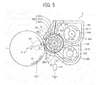
- FIG. 5 illustrates distribution of magnetic flux density superimposed on a schematic end-on axial view of the development device 3 .
- a magnet roller 302 d is provided inside the development roller 302 , and its position is fixed relative to the development device 3 .
- the magnet roller 302 d includes multiple magnets MG arranged in a circumferential direction of thereof, and a cylindrical sleeve 302 c provided outside the magnet roller 302 d rotates integrally with a rotary shaft 302 e .
- MG rotary shaft
- the magnet roller 302 d is fixed to the casing 301 , for example, so that each magnet MG faces in a predetermined direction.
- the development roller 302 transports the developer 320 carried on a surface of the sleeve 302 c , attracted by magnetic force exerted by the magnet MG, in the circumferential direction thereof as the sleeve 302 c rotates.
- reference characters GP 1 designates a gap between the photoconductor 1 and the development roller 302 (i.e., development gap), and GP 2 designates a gap between the development roller 302 and the partition 306 .
- FIG. 6 is a cross-sectional view of the development roller 302 along the axial direction thereof.
- reference character O- 302 a designates a center line passing through the center of rotation O- 302 of the development roller 302 .
- the development roller 302 further includes a fixed shaft 302 a fixed to the casing 301 , the magnet roller 302 d , which is cylindrical and united to the fixed shaft 302 a , the sleeve 302 c overlaying the magnet roller 302 d across a gap, and the rotary shaft 302 e united to the sleeve 302 c .
- the rotary shaft 302 e is rotatable relative to the fixed shaft 302 a via bearings 302 f , and the rotary shaft 302 e is driven by a driving unit, not shown.
- the multiple magnets MG are fixed on an outer circumferential surface of the magnet roller 302 d , arranged at predetermined intervals.
- the sleeve 302 c rotates around the magnets MG.
- the magnets MG form magnetic fields to cause developer particles to stand on end on the circumferential surface of the sleeve 302 c and to separate the developer particles from the sleeve 302 c .
- five magnets MG are provided inside the sleeve 302 c , thus generating five magnetic poles, as shown in the distribution of magnetic flux shown in FIG. 5 .
- the magnetic pole positioned on a vertical line connecting the center of rotation O- 302 of the development roller 302 and the center of rotation O- 2 of the photoconductor 1 is referred to as a magnetic pole P 1
- other magnetic poles are respectively referred to as magnetic poles P 2 , P 3 , P 4 , and P 5 from the upstream side in the rotational direction of the development roller 302 .
- the polarity of the magnetic poles P 1 , P 2 , P 3 , P 4 , and P 5 are north (N), south (S), N, N, and S, respectively.
- the magnetic poles P 1 through P 5 may have the reverse polarities to those shown in FIG. 5 .
- centers of the magnetic poles P 1 , P 2 , P 3 , and P 4 are substantially at eight o'clock, seven o'clock, five o'clock, and one o'clock, respectively.
- the development roller 302 In the development area A, the development roller 302 is not in direct contact with the photoconductor 1 , and the development gap GP 1 having a predetermined distance suitable for image development is kept between the development roller 302 and the photoconductor 1 . Developer particles are caused to stand on end on the circumferential surface of the development roller 302 in the magnetic pole P 1 and brought into contact with the surface of the photoconductor 1 . Thus, toner particles can adhere to the electrostatic latent image formed thereon, developing the latent image.
- a grounded power source VP for generating development bias is connected to the fixed shaft 302 a .
- Voltage from the power source VP connected to the fixed shaft 302 a is applied via the electroconductive bearings 302 f and the electroconductive rotary shaft 302 e to the sleeve 302 c .
- an electroconductive support body 31 that forms an innermost layer of the photoconductor 1 is grounded.
- an electrical field for conveying toner particles separated from carrier particles toward the photoconductor 1 is formed in the development area A, and accordingly the toner particles move toward the photoconductor 1 due to differences in electrical potential between the sleeve 302 c and the electrostatic latent image formed on the surface of the photoconductor 1 .
- the present embodiment describes development devices to be used in image forming apparatuses that involve an exposure process using optical writing light L. More specifically, the charging device 2 shown in FIG. 2 charges the photoconductor 1 uniformly to a negative electrical potential, and the portion on which an image is to be formed (i.e., an image portion) is exposed to the writing light L so as to reduce the amount of optical writing. Then, the image portion, that is, an electrostatic latent image, that has a reduced electrical potential is developed with toner particles whose polarity is negative, which is a method so-called “reversal development”.
- This is just an example, and, in development methods to which the features of the present invention are applicable are not limited to the description above regarding the polarity of charging potential of the photoconductor 1 .
- the developer 320 After being used in image development in the development area, the developer 320 is kept on the development roller 302 by the magnetic force exerted by the magnetic pole P 2 and is conveyed inside the casing 301 as the development roller 302 rotates.
- the portion of the casing 301 corresponding to the magnetic pole P 2 is positioned close to the circumferential surface of the sleeve 302 c and curved conforming to the circumferential surface of the sleeve 302 c . Therefore, scattering of toner particles is alleviated with sealing effects.
- the magnetic poles P 3 and P 4 positioned downstream from the magnetic pole P 2 in the rotational direction of the development roller 302 have an identical polarity. Consequently, magnetic force attracting the developer 320 to the surface of the development roller 302 becomes weaker between the magnetic poles P 3 and P 4 , and effects of releasing the developer 320 from the development roller 302 act in the release area 9 shown in FIGS. 2 and 4 .
- the developer 320 After image development, because toner therein has moved to the photoconductor 1 and adhered to the latent image, the developer 320 has a reduced toner concentration. Therefore, desired image density might not be attained if such developer 320 having a reduced toner concentration is not separated from the development roller 302 but is carried again to the development area A (hereinafter “carryover of developer”) and used in image development.
- the developer 320 is separated from the development roller 302 in the release area 9 (shown in FIG. 4 ) and collected in the collection compartment 301 C (shown in FIG. 5 ) separate from the supply compartment 301 S to prevent carryover of developer.
- the surface of the development roller 302 from which the developer 320 is separated reaches a portion facing the supply compartment 301 S as the development roller 302 rotates.
- the magnetic pole P 4 is present at that position, and the developer 320 flowing in the supply compartment 301 S is attracted to the attraction area 10 of the development roller 302 and carried thereon by the magnetic force exerted by the magnetic pole P 4 .
- the amount of the developer 320 carried by the magnetic force exerted by the magnetic pole P 4 on the development roller 302 is adjusted, after which the developer 320 is transported to the development area A.
- the magnetic pole P 5 positioned between the magnetic poles P 4 and P 1 serves as a developer conveyance pole for keeping developer on the surface of the development roller 302 in an area extending from the development doctor 303 to the development area A.
- FIG. 7 is a perspective view illustrating the components of the development device 4 assembled
- FIG. 8 is an exploded view of the components of the development device 4 .
- reference character O- 304 a represents a centerline that passes through the center of rotation O- 304 and parallels the centerline O- 302 a of the development roller 302 .
- the first conveyance screw 304 provided in the supply compartment 301 S includes a spiral blade 304 B fixed to a screw shaft 304 C and rotates clockwise in FIG. 7 on the centerline O- 304 a as indicated by an arrow shown in FIG. 7 .
- the first conveyance screw 304 transports developer from the back side to the front side in FIG. 7 as indicated by arrow 11 while agitating the developer.
- the first conveyance screw 304 transports developer in the axial direction from the back side to the front side in FIG. 7 .
- the second conveyance screw 305 provided in the collection compartment 301 C includes a spiral blade 305 B fixed to a screw shaft 305 J and rotates counterclockwise in FIG. 7 as indicated by an arrow shown in FIG. 7 on a centerline O- 305 a that passes through its center of rotation O- 305 and parallels the centerline O- 302 a of the development roller 302 .
- the second conveyance screw 305 transports developer from the front side to the back side in FIG. 7 as indicated by arrow 12 while agitating the developer.
- the second conveyance screw 305 transports developer in the axial direction from the front side to the back side in FIG. 7 , which is opposite the developer conveyance direction of the first conveyance screw 304 .
- the partition 306 provided between the first conveyance screw 304 and the second conveyance screw 305 thus separating the supply compartment 301 S including the first conveyance screw 304 from the collection compartment 301 C including the second conveyance screw 305 , is shaped like a cantilever supporter with one side thereof united to an inner face of the casing 301 on the side opposite the development roller 302 .
- the partition 306 is provided only in a center portion and is not present in both end portions in the long axis direction of the development roller 302 .
- the first and second conveyance screws 304 and 305 extend into both end portions in the long axis direction of the development roller 302 .
- developer is transported in the direction indicated by arrow 12 and then is blocked by a side wall of the casing 301 in the downstream end portion in the developer conveyance direction therein.
- the developer is piled against the side wall of the casing 301 and then moves in the direction indicated by arrow 13 through the opening 307 to the supply compartment 301 S.
- developer is transported in the direction indicated by arrow 11 and then flows down in the direction indicated by arrow 14 through the communication port 309 to the collection compartment 301 C.
- the developer can move between the supply compartment 301 S and the collection compartment 301 C in the both end portions in the long axis direction where the partition 306 is not present, and accordingly a developer circulation path in which developer flows in the order of arrows 11 , 14 , 12 , and 13 is formed.
- the partition 306 supports the developer 320 agitated by the first conveyance screw 304 from below, thus forming the supply compartment 301 S. Simultaneously, the partition 306 inhibits the developer separated from the development roller 302 in the release area 9 and collected in the collection compartment 301 C from moving to the supply compartment 301 S.
- the gap GP 2 between the circumferential surface of the development roller 302 and the partition 306 is preferably within a range of about 0.2 mm to 1 mm. If the gap GP 2 is less than 0.2 mm, the development roller 302 might contact the partition 306 due to eccentricities in rotation of the development roller 302 . If the gap GP 2 is greater than 1 mm, the effect of inhibiting the collected developer from moving to the supply compartment 301 S might be insufficient.
- the partition 306 functions even if positioned shifted from the release area 9 , the partition 306 might regulate a relatively large amount of developer in such an arrangement, thus increasing stress to the developer. Therefore, such an arrangement is not preferred unless arrangement described below is considered. Therefore, in the present embodiment, the release area 9 is disposed around the development roller 302 on the side opposite the photoconductor 1 and lower than the attraction area 10 , and the attraction area 10 is disposed adjacent to and downstream from the release area 9 in the rotational direction of the development roller 302 .
- the partition 306 is disposed in a portion between the release area 9 and the attraction area 10 , where the amount of developer adhering to the surface of the development roller 302 is extremely small so as to separate the space around the first conveyance screw 304 from the space around the second conveyance screw 305 . Moreover, an edge face of the partition 306 on the side of the development roller 302 faces the development roller 302 .
- the partition 306 can function because the partition 306 is provided in the portion where the amount of developer adhering to the surface of the development roller 302 is small. Additionally, stress to the developer caused by the partition 306 can be reduced. That is, the limitation in the size of the gap GP 2 between the development roller 302 and the partition 306 can be alleviated in designing the device. It is to be noted that stress to the developer can be further reduced by satisfying the range from about 0.2 mm to 1 mm as the size of the gap GP 2 , in addition to the above-described arrangement.
- the partition 306 is positioned so that the partition 306 is closest to the development roller 302 in a portion between the first conveyance screw 304 and the second conveyance screw 305 where the amount of developer adhering to the surface of the development roller 302 is extremely small, that is, within the release area 9 between the magnetic pole P 3 and the magnetic pole P 4 , where the density of magnetic flux on the surface of the development roller 302 is less than 10 mT.
- the bladed wheel 308 is provided instead of the spiral blade 305 B in the downstream end portion, in the area corresponding to the opening 307 , of the collection compartment 301 C in the developer conveyance direction of the second conveyance screw 305 .
- the bladed wheel 308 includes multiple planar blades radially extending from the screw shaft 305 J (centerline O- 305 a ) of the second conveyance screw 305 and flips up developer as the second conveyance screw 305 rotates.
- the centers of rotation O- 304 and O- 305 of the first and second conveyance screws 304 and 305 are substantially on an identical vertical line, and the bladed wheel 308 rotates counterclockwise in FIG. 4 while flipping up developer against the inner face of the casing 301 .
- the opening 307 extends from the position slightly shifted toward the inner face of the casing 301 from the vertical line connecting the centers of axes O- 304 and O- 305 to the inner face of the casing 301 so that the route in which the flipped developer moves is not blocked, and simultaneously the flipped developer does not fall toward the second conveyance screw 305 .
- the partition 306 is present on the side closer to the development roller 302 in the portion corresponding to the opening 307 similarly to the center portion in the longitudinal direction of the development roller 302 .
- the developer brought up through the opening 307 does not fall down to the second conveyance screw 305 but is attracted to the development roller 302 .
- the developer is either transported by the development roller 302 to the second conveyance screw 305 or to the first conveyance screw 304 .
- the developer can be circulated efficiently.
- the first conveyance screw 304 rotates clockwise FIG. 4 , opposite the direction in which the development roller 302 rotates. Generally, while transporting objects in their rotational directions, screws draw the object to be transported to the rotational direction. Therefore, the first conveyance screw 304 transports developer while drawing the developer to the side of the development roller 302 . Consequently, the amount of developer in contact with the development roller 302 can be increased, and developer can be supplied to the development roller 302 reliably.
- the second conveyance screw 305 rotates counterclockwise in FIG. 4 , which is identical to the direction in which the development roller 302 rotates.
- the second conveyance screw 305 transports developer while drawing the developer to the opposite side of the development roller 302 . Therefore, the developer once separated from the development roller 302 in the release area 9 by the magnetic force or the partition 306 can be prevented from adhering to the development roller 302 again.
- the developer having a reduced toner concentration after image development can be prevented from moving to the supply compartment 301 S in which the first conveyance screw 304 is provided.
- toner in the developer 302 contained in the development device 3 is consumed in image development, toner must be externally supplied to the developer in the development device 3 . It is preferred that the toner supply position be positioned further from the upstream end portion of the supply compartment 301 S on the developer circulation path, outside the portion facing the development area A of the development roller 302 , to prevent insufficiently charged toner from being supplied to the development area A.
- the communication port 309 is provided to transport the developer from the downstream end portion of the supply compartment 301 S to the upstream end portion of the collection compartment 301 C. Because the communication port 309 is preferably positioned outside the development area A so as not to cause shortage of developer supplied to the development area.
- the supply compartment 301 S is made longer than the development roller 302 in the axial direction of the developer carrier 302 so that its downstream end portion is positioned outside the development area A. In such a configuration, it is not necessary to expand the supply compartment 301 S further in the axial direction of the developer carrier 302 when toner is supplied to the extended portion.
- the toner supply port 310 is provided above the downstream end portion of the supply compartment 301 S (on the front side of the development device 3 ) where the communication port 309 is formed, outside the development area A. More specifically, the toner supply port 310 is formed in the casing 301 above the front-side end portion where the partition 306 is not present.
- toner supplied through the toner supply port 310 falls from the downstream end portion of the supply compartment 301 S, outside the area facing the development roller 302 (i.e., the development area A), through the communication port 309 to the upstream end portion of the collection compartment 301 C together with the developer.
- the toner is then transported in the collection compartment 301 C by the second conveyance screw 305 while being mixed with the developer.
- the developer flowing through the collection compartment 301 C is not supplied to the development roller 302 . Therefore, insufficiently charged developer in which the concentration of toner is uneven due to the toner newly supplied through the toner supply port 310 is not supplied to the development roller 302 nor is used in image development as is.
- the supplied toner is mixed with the developer collected from the development roller 302 , having a reduced toner concentration. Before reaching the downstream end portion of the collection compartment 301 C, the developer thus mixed can be charged sufficiently and the toner concentration can be equalized.
- the developer is brought up through the opening 307 to the supply compartment 301 S by the bladed wheel 308 or the like. While being transported to the front side of the device by the first conveyance screw 304 , the developer is supplied to the development roller 302 and used in image development.
- Toner supply is performed in such a downstream end portion of the supply compartment 301 S, that is, in an area adjacent to the development area A of the development roller 302 .
- toner is supplied downward to the downstream end portion of the supply compartment 301 S. Therefore, before being mixed in developer, the supplied toner particles can partly float in the air because they are fine particles having a small particle diameter.
- the amount of developer is smaller in the downstream end portion of the supply compartment 301 S than in the upstream end portion of the supply compartment 301 S. Therefore, space above the developer is larger on the downstream side than the upstream side in the supply compartment 301 S. Therefore, a greater amount of toner particles can float in the downstream end portion of the supply compartment 301 S compared with a case in which toner is supplied in the upstream end portion thereof.
- the downstream end portion of the supply compartment 301 S is adjacent to the area facing the development area A of the development roller 302 as described above, the floating toner particles just after supplied to the supply compartment 301 S are likely to move to the area facing the development area A and further be carried by the development roller 302 to the development area A. If such toner particles just after supplied are transported to the development area A, it is possible that the toner particles scatter in the background of output images or around the interior of the image forming apparatus.
- providing the toner supply port 310 in the downstream end portion of the supply compartment 301 S as in the present embodiment has an advantage that supplied toner can be mixed in developer promptly, compared with a comparative development device in which the toner supply port is provided in the collection compartment.
- the toner supply port is provided in the collection compartment, developer is transported in the collection compartment together with the supplied toner accumulated on the surface of the developer, and most of the supplied toner can remain on the surface of the developer until transported to the downstream end of the collection compartment.
- the supplied toner accumulating on the surface of the developer is mixed with developer in the downstream end of the collection compartment where developer is piled up and then is brought up through the opening to the supply compartment.
- the toner supply port 310 is provided in the downstream end portion of the supply compartment 301 S
- developer flowing in the supply compartment 301 S is supplied to the toner supplied through the toner supply port 310 down on the surface of the developer.
- the supplied toner is further mixed with developer while falling through the communication port 309 .
- the mixed developer is then transported through the collection compartment 301 C by the second conveyance screw 305 to the downstream end portion of the collection compartment 301 C while agitated also with the developer collected from the development roller 302 , having a reduced toner concentration.
- the developer is further agitated in the portion where developer is piled up through the opening 307 , thus brought up to the supply compartment 301 S.
- the supplied toner can be substantially mixed with developer promptly in the present embodiment, still, there can be toner particles not mixed in the developer but float in the air.
- the spiral blade 304 B of the first conveyance screw 304 agitates air in the space where the supplied toner falls when the first conveyance screw 304 rotates.
- the blade spiral 304 B stirs up the supplied toner that is not mixed in the developer.
- the portion of developer where the supplied toner falls down is agitated, it can happen that the supplied toner is stirred up again from the developer after being mixed therein.
- the present embodiment inhibits the floating supplied toner in the downstream end portion of the supply compartment 301 S from being supplied to the development area A as follows.
- FIG. 9 is a schematic top view illustrating the interior of the supply compartment 301 S.
- developer is partly carried onto the surface of the development roller 302 while being transported downstream (in FIG. 9 , to the right). Therefore, the amount of developer is greater on the upstream side and decreases downstream (to the right in FIG. 9 ) in the supply compartment 301 S.
- the developer flows downstream and, in the downstream end portion, falls down through the communication port 309 to the collection compartment 301 C. Accordingly, an airflow K 0 flowing in the same direction as the direction in which the developer flows is present above the developer in the downstream end portion of the supply compartment 301 S.
- a rib 311 serving as an airflow path limiter, is provided in the downstream end portion of the supply compartment 301 S so as to restricts an airflow path in which the airflow K 0 flows above the developer in the supply compartment 301 S, in particular, to reduce a cross-sectional area of the airflow path.
- the rib 311 is positioned closer to the development area of the development roller 302 than the toner supply port 310 , that is, upstream from the toner supply port 310 in the developer conveyance direction or axial direction of the development roller 302 .
- the rib 311 blocks partly or narrows the path through which the floating toner particles, supplied through the toner supply port 310 , move toward the development roller 301 .
- the velocity of airflow increases in the narrowed portion because the amount of air flowing does not change in front and the back of the narrowed portion. Consequently, an airflow K 1 that hinders movement of the floating toner particles to the side of the development roller 302 becomes stronger than the airflow K 0 flowing in a portion where the rib 311 is not provided. Therefore, the amount of floating toner particles that move to the side of the development roller 302 can be effectively reduced compared with a case in which the rib 311 is not provided.
- the rib 311 may extend about half the width of the supply compartment 301 S, that is, the length of the supply compartment 301 S in the direction horizontal and perpendicular to the axial direction of the development roller 302 . It is to be noted that, in the supply compartment 301 S, the rib 311 extends not only in the space above the developer but also into the area where the developer flows as shown in FIG. 10 . Although the rib 311 hinders the flow of developer in the supply compartment 301 S in this configuration to some extent, the developer can flow through the gap between the rib 311 and an inner face of the supply compartment 301 S to the downstream end portion of the supply compartment 301 S. Thus, circulation of developer is not inhibited.
- the amount of developer, hindered by the rib 311 increases on the downstream side in the supply compartment 301 S, the surface level of the developer rises. Consequently, the cross-sectional area of the airflow path through which the floating supplied toner particles move toward the development roller 302 can be further restricted. Therefore, the airflow K 1 that inhibits the floating toner particles from moving toward the development roller 302 can become stronger, thus reducing the amount of the toner particles moving to the development roller 302 more effectively.
- the rib 311 is positioned closer to the development roller 302 in the supply compartment 301 S on a virtual plane perpendicular to the screw shaft 304 C of the first conveyance screw 304 , that is, in the direction horizontal and perpendicular to the axial direction of the development roller 302 .
- This arrangement enables the rib 311 to block a linear route through which the supplied toner, fallen through the toner supply port 310 , moves toward the development roller 302 , thus attaining higher effects of inhibiting the supplied toner from moving toward the development roller 302 with the rib 311 .
- the toner lands on the developer in a portion away from the development roller 302 . Accordingly, before supplied onto the development roller 302 , such toner particles are transported downstream in the supply compartment 301 S and are not supplied to the development area A.
- the spiral blade 304 B attached to the screw shaft 304 C of the first conveyance screw 304 does not contact the rib 311 .
- the spiral blade 304 B is cut off in the portion corresponding to the rib 311 .
- the spiral blade 304 B of the first conveyance screw 304 may be reduced in size in the portion corresponding to the rib 311 .
- the spiral blade 304 B of the first conveyance screw 304 flips up the developer as described above, which is not desirable. Therefore, it is more preferable that the spiral blade 304 B of the first conveyance screw 304 be removed in the area extending from the position facing the rib 311 to the downstream end thereof in the developer conveyance direction. It is to be noted that removing that portion of the spiral blade 304 B from the first conveyance screw 304 does not impose adverse effects in circulation of developer because developer moves down to the communication port 309 under its own weight.
- FIG. 11 is a graph illustrating results of an experiment to evaluate scattering of toner in backgrounds on the photoconductor 1 when the rib 311 is provided (first condition) and is not provided (second condition).
- scattering of toner in backgrounds means a phenomenon that toner adheres to the non-image area of the photoconductor 1 where an electrostatic latent image is not formed. Scattering of toner in backgrounds occurs frequently or the degree of toner scattering increases when the ratio of insufficiently charged toner is large, that is, frictional charging between toner and carrier is insufficient.
- toner particles adhering to the non-image area of the photoconductor 1 was collected with transparent adhesive tape, and density of the collected toner particles was measured with an X-Rite spectrophotometric color densitometer. As can be seen from FIG.
- the degree of toner scattering in backgrounds was alleviated in the configuration in which the rib 311 was provided (first condition).
- the degree of toner scattering in backgrounds was thus alleviated because the rib 311 inhibited the supplied toner from being carried on the development roller 302 , thereby preventing it from being used in image development.
- the rib 311 can not only blocks the movement of floating toner to the development area by itself but also increase the strength of the airflow inhibiting the movement of floating toner to the development area. Therefore, the amount of floating toner moving to the development area can be reduced effectively.
- FIG. 12 illustrates a variation of the rib 311 .
- a face 312 of a rib 311 A on the side receiving the developer flowing in the supply compartment 301 S is inclined downstream in the developer conveyance direction therein. That is, a first end of the face 312 on the side of the gap between the rib 311 A and the inner wall of the supply compartment 301 S is positioned downstream from a second end opposite the first end of the rib 311 A.
- the rib 311 A may be triangular or trapeziform as shown in FIG. 12 when viewed from above.
- the inclined surface 312 (shown in FIG. 12 ) of the rib 311 A can also inhibit the developer in contact with the rib 311 A from accumulating there in the configuration in which the rib 311 A extends into the area where the developer flows in the supply compartment 301 S as in the present embodiment.
- FIG. 13 is a schematic top view illustrating an interior of a supply compartment 301 S 1 of a development device 3 A according to the first variation.
- FIG. 14 is a schematic side view of the development device 3 A according to the first variation.
- a toner guide frame 313 forming a toner guide path 314 is provided in a supply compartment 301 S 1 for guiding the supplied toner fallen through the toner supply port 310 to a bottom portion of the supply compartment 301 S 1 .
- a surface 313 A, which receives the developer flowing in the supply compartment 301 S 1 , of the toner guide frame 313 serves as the airflow path limiter instead of the above-described rib 311 .
- the lower end of the toner guide frame 313 is positioned slightly higher than the screw shaft 304 C of a first conveyance screw 304 - 1 provided in the supply compartment 301 S 1 .
- the spiral blade 304 B of the first conveyance screw 304 does not present in the area corresponding to the toner guide frame 313 .
- the toner guide frame 313 can better restrict diffusion of the supplied toner in the supply compartment 301 S 1 , compared with the above-described configuration in which the supplied toner falls directly to the supply compartment 301 S through the toner supply port 310 . Therefore, the floating supplied toner can be better inhibited from moving toward the development roller 302 and being used in image development.
- the toner guide frame 313 may extend beneath the screw shaft 304 C of the first conveyance screw 304 - 1 as indicated by broken lines shown in FIG. 14 .
- the toner guide frame 313 may be positioned on the side away from the development roller 302 as in a supply compartment 301 S 2 shown in FIG. 15 .
- FIG. 16 is a schematic end-on axial view illustrating a configuration of developer circulation in the second variation.
- developer circulation mechanism in the developer circulation mechanism according to the second variation, developer is circulated in three separate developer conveyance paths. It is to be noted that the configuration of the developer circulation mechanism using three developer conveyance paths is not limited to that of the second variation.
- the development device 3 B includes a supply compartment 301 S 3 in which a first conveyance screw 304 is provided, a collection compartment 301 C 3 in which a second conveyance screw 305 is provided, and an agitation compartment 301 A that receives developer from a downstream end portion of the supply compartment 301 S 3 and that of the collection compartment 301 C 3 and returns the developer to an upstream end portion of the supply compartment 301 S 3 .
- a third conveyance screw 315 is provided in the agitation compartment 301 A.
- developer is transported in an identical or similar direction in the supply compartment 301 S 3 and the collection compartment 301 C 3 , which is from the back side to the front side of the development device 3 B.
- a communication port 309 is formed in a downstream end portion of the supply compartment 301 S 3 and communicates with an upstream end portion of the agitation compartment 301 A, and a communication port connecting a downstream end portion of the collection compartment 301 C 3 and the upstream end portion of the agitation compartment 301 A is provided as well.
- developer is circulated as follows in the second variation.
- a first route is from the supply compartment 301 S 3 in which the first conveyance screw 304 is provided to the development roller 302 , the collection compartment 301 C 3 in which the second conveyance screw 305 is provided, and the agitation compartment 301 A in which the third conveyance member 315 is provided, and then returns to the supply compartment 301 S 3 .
- a second route is from the supply compartment 301 S 3 in which the first conveyance screw 304 is provided to the agitation compartment 301 A in which the third conveyance member 315 is provided and then returns to the supply compartment 301 S 3 .
- the collection compartment 301 C 3 as well as the agitation compartment 301 A are positioned beneath the supply compartment 301 S 3 , and the developer transported to the downstream end portion of the supply compartment 301 S 3 is transported through the communication port 309 to the agitation compartment 301 A.
- a toner supply port 310 is provided in the downstream end portion of the supply compartment 301 S 3 . Therefore, similarly to the above-described embodiment, to inhibit toner supplied through the toner supply port 310 from floating and moving to the development roller 302 , an airflow path limiter such as the rib 311 shown in FIG. 9 is provided. Needless to say, the airflow path limiter is not limited to the rib 311 , and alternatively, for example, the toner guide frame 313 according to the first variation may be used.
Landscapes
- Physics & Mathematics (AREA)
- General Physics & Mathematics (AREA)
- Dry Development In Electrophotography (AREA)
Applications Claiming Priority (2)
| Application Number | Priority Date | Filing Date | Title |
|---|---|---|---|
| JP2009-290420 | 2009-12-22 | ||
| JP2009290420A JP5500422B2 (ja) | 2009-12-22 | 2009-12-22 | 現像装置、並びに、これを備えたプロセスカートリッジ及び画像形成装置 |
Publications (2)
| Publication Number | Publication Date |
|---|---|
| US20110150525A1 US20110150525A1 (en) | 2011-06-23 |
| US8433224B2 true US8433224B2 (en) | 2013-04-30 |
Family
ID=43415202
Family Applications (1)
| Application Number | Title | Priority Date | Filing Date |
|---|---|---|---|
| US12/952,519 Expired - Fee Related US8433224B2 (en) | 2009-12-22 | 2010-11-23 | Development device, process cartridge including same, and image forming apparatus including same |
Country Status (4)
| Country | Link |
|---|---|
| US (1) | US8433224B2 (de) |
| EP (1) | EP2339408A3 (de) |
| JP (1) | JP5500422B2 (de) |
| CN (1) | CN102103345B (de) |
Cited By (2)
| Publication number | Priority date | Publication date | Assignee | Title |
|---|---|---|---|---|
| US9405223B2 (en) | 2014-06-12 | 2016-08-02 | Ricoh Company, Ltd. | Developing device, image forming apparatus, and process cartridge |
| US20180277401A1 (en) * | 2017-03-27 | 2018-09-27 | Ebara Corporation | Substrate processing method and apparatus |
Families Citing this family (19)
| Publication number | Priority date | Publication date | Assignee | Title |
|---|---|---|---|---|
| JP5585871B2 (ja) | 2010-08-31 | 2014-09-10 | 株式会社リコー | 現像装置、並びに、これを備えたプロセスカートリッジ及び画像形成装置 |
| JP5598311B2 (ja) | 2010-12-22 | 2014-10-01 | 株式会社リコー | 現像装置、プロセスカートリッジおよび画像形成装置 |
| JP5692642B2 (ja) | 2011-02-14 | 2015-04-01 | 株式会社リコー | 現像装置、画像形成装置、及びプロセスカートリッジ |
| JP5773245B2 (ja) | 2011-02-28 | 2015-09-02 | 株式会社リコー | 現像装置、画像形成装置、及びプロセスカートリッジ |
| US8688017B2 (en) * | 2011-03-11 | 2014-04-01 | Oki Data Corporation | Image formation unit and image formation apparatus |
| JP2013020062A (ja) * | 2011-07-11 | 2013-01-31 | Canon Inc | 現像装置 |
| JP5839263B2 (ja) | 2011-08-01 | 2016-01-06 | 株式会社リコー | 現像装置、プロセスカートリッジ、及び、画像形成装置 |
| JP5765624B2 (ja) | 2011-08-19 | 2015-08-19 | 株式会社リコー | 現像装置、画像形成装置、及びプロセスカートリッジ |
| JP5950156B2 (ja) | 2011-09-09 | 2016-07-13 | 株式会社リコー | プロセスカートリッジ、及び、画像形成装置 |
| JP2014102495A (ja) | 2012-10-23 | 2014-06-05 | Ricoh Co Ltd | 現像装置および画像形成装置 |
| JP6119323B2 (ja) | 2013-03-13 | 2017-04-26 | 株式会社リコー | 現像装置、プロセスカートリッジ及び画像形成装置 |
| US9625851B2 (en) | 2015-02-13 | 2017-04-18 | Ricoh Company, Ltd. | Developing device and image forming apparatus incorporating same |
| JP6620978B2 (ja) | 2015-10-22 | 2019-12-18 | 株式会社リコー | 現像装置、画像形成装置およびプロセスカートリッジ |
| US10031441B2 (en) | 2015-10-26 | 2018-07-24 | Ricoh Company, Ltd. | Developing device, and image forming apparatus and process cartridge incorporating same |
| US9791806B1 (en) * | 2016-04-25 | 2017-10-17 | Lexmark International, Inc. | Developer roll having magnetic zones of varying axial length for a dual component development electrophotographic image forming device |
| JP6873822B2 (ja) * | 2017-05-26 | 2021-05-19 | キヤノン株式会社 | 現像装置 |
| JP2019028322A (ja) | 2017-07-31 | 2019-02-21 | 株式会社リコー | 現像装置及びプロセスカートリッジ及び画像形成装置 |
| JP7148890B2 (ja) * | 2018-10-10 | 2022-10-06 | 株式会社リコー | 画像形成装置 |
| JP2020112690A (ja) * | 2019-01-11 | 2020-07-27 | ヒューレット−パッカード デベロップメント カンパニー エル.ピー.Hewlett‐Packard Development Company, L.P. | 画像形成システム |
Citations (21)
| Publication number | Priority date | Publication date | Assignee | Title |
|---|---|---|---|---|
| US5381217A (en) * | 1991-06-21 | 1995-01-10 | Kabushiki Kaisha Toshiba | Detachably mounted toner unit having a toner supply unit and a toner recovery housing unit |
| US5845183A (en) | 1994-05-12 | 1998-12-01 | Ricoh Company, Ltd. | Developing device for an image forming apparatus |
| JP2002006599A (ja) | 2000-06-27 | 2002-01-09 | Canon Inc | 現像装置および画像形成装置 |
| US6505014B2 (en) | 2000-09-29 | 2003-01-07 | Ricoh Company, Ltd. | Image forming apparatus and an image forming process unit |
| US6671484B2 (en) | 2000-09-05 | 2003-12-30 | Ricoh Company, Ltd. | Image forming apparatus having developing device with magnet roller with particular magnetic flux density |
| US6721516B2 (en) | 2001-01-19 | 2004-04-13 | Ricoh Company, Ltd. | Image forming apparatus |
| US7035575B2 (en) | 2003-04-16 | 2006-04-25 | Ricoh Company, Ltd. | Developing device, image forming apparatus, and process cartridge |
| JP2007072347A (ja) | 2005-09-09 | 2007-03-22 | Ricoh Co Ltd | 現像装置、プロセスカートリッジ、及び、画像形成装置 |
| EP1791035A1 (de) | 2005-11-25 | 2007-05-30 | Ricoh Company, Ltd. | Entwicklereinheit für einen Zweikomponentenentwickler |
| JP2007163933A (ja) | 2005-12-15 | 2007-06-28 | Samsung Electronics Co Ltd | 現像装置および画像形成装置 |
| US20080056747A1 (en) | 2006-09-04 | 2008-03-06 | Yasuo Miyoshi | Developing device, process cartridge and image forming apparatus |
| US7536141B2 (en) | 2005-04-11 | 2009-05-19 | Ricoh Company, Ltd. | Developing device, process cartridge and image forming apparatus |
| US20090169264A1 (en) | 2007-12-26 | 2009-07-02 | Yasuo Miyoshi | Developing device, process cartridge, and image forming apparatus, method of developing latent image |
| US20090220252A1 (en) * | 2008-02-28 | 2009-09-03 | Kabushiki Kaisha Toshiba | Image forming apparatus and image forming method |
| US20090232558A1 (en) | 2008-03-11 | 2009-09-17 | Norio Kudo | Developing device and image forming apparatus including same |
| US20090238610A1 (en) | 2008-03-18 | 2009-09-24 | Yasuo Miyoshi | Developing device, process cartridge, and image forming apparatus |
| US7599649B2 (en) | 2006-08-22 | 2009-10-06 | Ricoh Co., Ltd | Development device and process cartridge including development device |
| US7650101B2 (en) | 2004-11-26 | 2010-01-19 | Ricoh Co., Ltd. | Image forming apparatus capable of effectively developing images |
| US7769326B2 (en) | 2006-12-13 | 2010-08-03 | Ricoh Company, Ltd. | Developing device, process cartridge, and image forming apparatus |
| US20100202805A1 (en) | 2009-02-06 | 2010-08-12 | Yasuo Miyoshi | Development device, process cartridge, and image forming apparatus |
| US20100215401A1 (en) | 2009-02-24 | 2010-08-26 | Yoshihiro Fujiwara | Development device, process cartridge, and image forming apparatus |
Family Cites Families (10)
| Publication number | Priority date | Publication date | Assignee | Title |
|---|---|---|---|---|
| JPH09106161A (ja) * | 1995-10-11 | 1997-04-22 | Ricoh Co Ltd | 現像装置 |
| JPH09114243A (ja) * | 1995-10-20 | 1997-05-02 | Fuji Xerox Co Ltd | 現像装置 |
| JPH10198165A (ja) * | 1997-01-06 | 1998-07-31 | Toshiba Corp | 現像装置および画像形成装置 |
| JP3894998B2 (ja) * | 1997-03-19 | 2007-03-22 | 株式会社東芝 | 現像装置 |
| JP2004133187A (ja) * | 2002-10-10 | 2004-04-30 | Canon Inc | 電子写真装置 |
| US7171137B2 (en) * | 2003-10-30 | 2007-01-30 | Samsung Electronics Co., Ltd. | Developing apparatus and image forming equipment and method thereof |
| JP2006171037A (ja) * | 2004-12-10 | 2006-06-29 | Canon Inc | 現像剤補給装置及び画像形成装置 |
| JP5012254B2 (ja) * | 2007-06-26 | 2012-08-29 | 富士ゼロックス株式会社 | 画像形成装置 |
| JP5269379B2 (ja) * | 2007-10-04 | 2013-08-21 | シャープ株式会社 | 現像装置およびそれを備える画像形成装置、ならびにトナーの補給方法 |
| JP2009290420A (ja) | 2008-05-28 | 2009-12-10 | Konica Minolta Business Technologies Inc | 画像形成装置及び安定化制御方法 |
-
2009
- 2009-12-22 JP JP2009290420A patent/JP5500422B2/ja not_active Expired - Fee Related
-
2010
- 2010-11-23 US US12/952,519 patent/US8433224B2/en not_active Expired - Fee Related
- 2010-11-25 EP EP10192592A patent/EP2339408A3/de not_active Withdrawn
- 2010-12-22 CN CN2010105996218A patent/CN102103345B/zh not_active Expired - Fee Related
Patent Citations (24)
| Publication number | Priority date | Publication date | Assignee | Title |
|---|---|---|---|---|
| US5381217A (en) * | 1991-06-21 | 1995-01-10 | Kabushiki Kaisha Toshiba | Detachably mounted toner unit having a toner supply unit and a toner recovery housing unit |
| US5845183A (en) | 1994-05-12 | 1998-12-01 | Ricoh Company, Ltd. | Developing device for an image forming apparatus |
| JP2002006599A (ja) | 2000-06-27 | 2002-01-09 | Canon Inc | 現像装置および画像形成装置 |
| US6671484B2 (en) | 2000-09-05 | 2003-12-30 | Ricoh Company, Ltd. | Image forming apparatus having developing device with magnet roller with particular magnetic flux density |
| US6505014B2 (en) | 2000-09-29 | 2003-01-07 | Ricoh Company, Ltd. | Image forming apparatus and an image forming process unit |
| US6901233B2 (en) | 2001-01-19 | 2005-05-31 | Ricoh Company, Ltd. | Image forming apparatus |
| US6721516B2 (en) | 2001-01-19 | 2004-04-13 | Ricoh Company, Ltd. | Image forming apparatus |
| US7035575B2 (en) | 2003-04-16 | 2006-04-25 | Ricoh Company, Ltd. | Developing device, image forming apparatus, and process cartridge |
| US20100014895A1 (en) | 2004-11-26 | 2010-01-21 | Hiroshi Hosokawa | Image forming apparatus capable of effectively developing images |
| US7650101B2 (en) | 2004-11-26 | 2010-01-19 | Ricoh Co., Ltd. | Image forming apparatus capable of effectively developing images |
| US7536141B2 (en) | 2005-04-11 | 2009-05-19 | Ricoh Company, Ltd. | Developing device, process cartridge and image forming apparatus |
| JP2007072347A (ja) | 2005-09-09 | 2007-03-22 | Ricoh Co Ltd | 現像装置、プロセスカートリッジ、及び、画像形成装置 |
| EP1791035A1 (de) | 2005-11-25 | 2007-05-30 | Ricoh Company, Ltd. | Entwicklereinheit für einen Zweikomponentenentwickler |
| US20070122202A1 (en) | 2005-11-25 | 2007-05-31 | Kenichi Taguma | Developing unit and image forming apparatus including the same |
| JP2007163933A (ja) | 2005-12-15 | 2007-06-28 | Samsung Electronics Co Ltd | 現像装置および画像形成装置 |
| US7599649B2 (en) | 2006-08-22 | 2009-10-06 | Ricoh Co., Ltd | Development device and process cartridge including development device |
| US20080056747A1 (en) | 2006-09-04 | 2008-03-06 | Yasuo Miyoshi | Developing device, process cartridge and image forming apparatus |
| US7769326B2 (en) | 2006-12-13 | 2010-08-03 | Ricoh Company, Ltd. | Developing device, process cartridge, and image forming apparatus |
| US20090169264A1 (en) | 2007-12-26 | 2009-07-02 | Yasuo Miyoshi | Developing device, process cartridge, and image forming apparatus, method of developing latent image |
| US20090220252A1 (en) * | 2008-02-28 | 2009-09-03 | Kabushiki Kaisha Toshiba | Image forming apparatus and image forming method |
| US20090232558A1 (en) | 2008-03-11 | 2009-09-17 | Norio Kudo | Developing device and image forming apparatus including same |
| US20090238610A1 (en) | 2008-03-18 | 2009-09-24 | Yasuo Miyoshi | Developing device, process cartridge, and image forming apparatus |
| US20100202805A1 (en) | 2009-02-06 | 2010-08-12 | Yasuo Miyoshi | Development device, process cartridge, and image forming apparatus |
| US20100215401A1 (en) | 2009-02-24 | 2010-08-26 | Yoshihiro Fujiwara | Development device, process cartridge, and image forming apparatus |
Non-Patent Citations (1)
| Title |
|---|
| Extended European Search Report issued Apr. 11, 2012, in European Patent Application No. 10192592.3. |
Cited By (3)
| Publication number | Priority date | Publication date | Assignee | Title |
|---|---|---|---|---|
| US9405223B2 (en) | 2014-06-12 | 2016-08-02 | Ricoh Company, Ltd. | Developing device, image forming apparatus, and process cartridge |
| US20180277401A1 (en) * | 2017-03-27 | 2018-09-27 | Ebara Corporation | Substrate processing method and apparatus |
| US10811284B2 (en) * | 2017-03-27 | 2020-10-20 | Ebara Corporation | Substrate processing method and apparatus |
Also Published As
| Publication number | Publication date |
|---|---|
| JP2011133533A (ja) | 2011-07-07 |
| CN102103345B (zh) | 2013-08-21 |
| JP5500422B2 (ja) | 2014-05-21 |
| US20110150525A1 (en) | 2011-06-23 |
| EP2339408A3 (de) | 2012-05-09 |
| EP2339408A8 (de) | 2011-09-14 |
| CN102103345A (zh) | 2011-06-22 |
| EP2339408A2 (de) | 2011-06-29 |
Similar Documents
| Publication | Publication Date | Title |
|---|---|---|
| US8433224B2 (en) | Development device, process cartridge including same, and image forming apparatus including same | |
| US8989621B2 (en) | Development device, and process cartridge and image forming apparatus including same | |
| JP4861152B2 (ja) | 現像装置及びプロセスカートリッジ並びに画像形成装置 | |
| US8620194B2 (en) | Developing device, process cartridge, image forming apparatus, and developer discharge device having a discharge port | |
| US8873979B2 (en) | Development device, process cartridge, and image forming apparatus incorporating same | |
| US8027623B2 (en) | Developing device, process cartridge, and image forming apparatus having a discharge port facing a section of a transport member without a screw part | |
| US8135314B2 (en) | Developing device, process cartridge, and image forming apparatus, method of developing latent image | |
| EP1168098A2 (de) | Entwicklerzufuhrbehälter und Bilderzeugungsgerät, auf das ein solcher Behälter placiert werden kann | |
| KR20130048693A (ko) | 현상 장치 및 화상 형성 장치 | |
| JP2006047886A (ja) | 現像装置、カートリッジ及び画像形成装置 | |
| KR20120135369A (ko) | 현상기 및 이를 채용한 전자사진방식 화상형성장치 | |
| JP5689219B2 (ja) | 現像装置、プロセスカートリッジ及び画像形成装置 | |
| JP4339276B2 (ja) | 現像装置およびこの現像装置が適用された画像形成装置 | |
| US9310718B2 (en) | Development device and image forming apparatus including the same | |
| JP2011170188A (ja) | 現像装置、並びに、これを備えたプロセスカートリッジ及び画像形成装置 | |
| JP5386960B2 (ja) | 現像装置、プロセスカートリッジ及び画像形成装置 | |
| JP4639164B2 (ja) | 画像形成装置 | |
| JP5510734B2 (ja) | 現像装置、プロセスカートリッジ、及び、画像形成装置 | |
| JP2007003953A (ja) | 現像装置 | |
| JP2006003602A (ja) | 現像方法、現像装置及び画像形成装置 | |
| JPH11184225A (ja) | 現像装置 | |
| JP2007156012A (ja) | 現像装置、プロセスカートリッジ、及び、画像形成装置 | |
| JP2005164999A (ja) | 現像装置及び画像形成装置 | |
| JP2014032340A (ja) | 現像装置、プロセスカートリッジ及び画像形成装置 | |
| JP2011081281A (ja) | 現像装置、プロセスカートリッジ、及び、画像形成装置 |
Legal Events
| Date | Code | Title | Description |
|---|---|---|---|
| AS | Assignment |
Owner name: RICOH COMPANY LIMITED, JAPAN Free format text: ASSIGNMENT OF ASSIGNORS INTEREST;ASSIGNORS:FUJIWARA, YOSHIHIRO;MIYOSHI, YASUO;HOSOKAWA, HIROSHI;AND OTHERS;SIGNING DATES FROM 20101116 TO 20101117;REEL/FRAME:025399/0391 |
|
| FEPP | Fee payment procedure |
Free format text: PAYOR NUMBER ASSIGNED (ORIGINAL EVENT CODE: ASPN); ENTITY STATUS OF PATENT OWNER: LARGE ENTITY |
|
| STCF | Information on status: patent grant |
Free format text: PATENTED CASE |
|
| FPAY | Fee payment |
Year of fee payment: 4 |
|
| FEPP | Fee payment procedure |
Free format text: MAINTENANCE FEE REMINDER MAILED (ORIGINAL EVENT CODE: REM.); ENTITY STATUS OF PATENT OWNER: LARGE ENTITY |
|
| LAPS | Lapse for failure to pay maintenance fees |
Free format text: PATENT EXPIRED FOR FAILURE TO PAY MAINTENANCE FEES (ORIGINAL EVENT CODE: EXP.); ENTITY STATUS OF PATENT OWNER: LARGE ENTITY |
|
| STCH | Information on status: patent discontinuation |
Free format text: PATENT EXPIRED DUE TO NONPAYMENT OF MAINTENANCE FEES UNDER 37 CFR 1.362 |
|
| FP | Lapsed due to failure to pay maintenance fee |
Effective date: 20210430 |