US8429829B2 - Measuring device - Google Patents
Measuring device Download PDFInfo
- Publication number
- US8429829B2 US8429829B2 US13/073,625 US201113073625A US8429829B2 US 8429829 B2 US8429829 B2 US 8429829B2 US 201113073625 A US201113073625 A US 201113073625A US 8429829 B2 US8429829 B2 US 8429829B2
- Authority
- US
- United States
- Prior art keywords
- measuring
- measuring device
- stop
- measuring head
- head
- Prior art date
- Legal status (The legal status is an assumption and is not a legal conclusion. Google has not performed a legal analysis and makes no representation as to the accuracy of the status listed.)
- Active, expires
Links
Images


Classifications
-
- B—PERFORMING OPERATIONS; TRANSPORTING
- B24—GRINDING; POLISHING
- B24B—MACHINES, DEVICES, OR PROCESSES FOR GRINDING OR POLISHING; DRESSING OR CONDITIONING OF ABRADING SURFACES; FEEDING OF GRINDING, POLISHING, OR LAPPING AGENTS
- B24B49/00—Measuring or gauging equipment for controlling the feed movement of the grinding tool or work; Arrangements of indicating or measuring equipment, e.g. for indicating the start of the grinding operation
- B24B49/02—Measuring or gauging equipment for controlling the feed movement of the grinding tool or work; Arrangements of indicating or measuring equipment, e.g. for indicating the start of the grinding operation according to the instantaneous size and required size of the workpiece acted upon, the measuring or gauging being continuous or intermittent
- B24B49/04—Measuring or gauging equipment for controlling the feed movement of the grinding tool or work; Arrangements of indicating or measuring equipment, e.g. for indicating the start of the grinding operation according to the instantaneous size and required size of the workpiece acted upon, the measuring or gauging being continuous or intermittent involving measurement of the workpiece at the place of grinding during grinding operation
- B24B49/045—Specially adapted gauging instruments
-
- B—PERFORMING OPERATIONS; TRANSPORTING
- B24—GRINDING; POLISHING
- B24B—MACHINES, DEVICES, OR PROCESSES FOR GRINDING OR POLISHING; DRESSING OR CONDITIONING OF ABRADING SURFACES; FEEDING OF GRINDING, POLISHING, OR LAPPING AGENTS
- B24B5/00—Machines or devices designed for grinding surfaces of revolution on work, including those which also grind adjacent plane surfaces; Accessories therefor
- B24B5/36—Single-purpose machines or devices
- B24B5/42—Single-purpose machines or devices for grinding crankshafts or crankpins
Definitions
- the invention relates to a measuring device. More particularly, the invention relates to a measuring device for in-process measurement of test specimens during a machining process on a machine tool, in particular a machine tool such as a grinding machine.
- crank pins of the crankshaft must be ground to size on a grinding machine. To ensure that the grinding operation is ended as soon as a desired size is reached, it is necessary to continuously check the crank pin during the machining operation, in particular with regard to its diameter and roundness, within the scope of an in-process measurement method.
- EP-A-0859689 discloses a corresponding measuring device.
- a measuring device is known from EP-A-1370391 which is used for in-process measurement of crank pins during a grinding operation on a grinding machine.
- the known measuring device has a measuring head which is connected via a rod assembly to a base body of the measuring device so as to be pivotable about a first pivot axis.
- the known measuring device also has a means for pivoting the measuring head in and out of the measuring position.
- the measuring head is pivoted by the means provided for this purpose into a measuring position in which the measuring head, for example using a measuring prism, comes to rest against the crank pin to be measured.
- the crank pin undergoes an orbital rotation about the rotational axis of the crankshaft.
- the grinding wheel remains in contact with the crank pin, and for this purpose is movably supported radially with respect to the rotational axis of the crankshaft.
- the measuring head follows the motions of the crank pin.
- the base body of the measuring device is connected to a base body of the grinding machine, so that during the grinding operation the measuring device is moved in the radial direction of the crankshaft, synchronously with the grinding wheel of the grinding machine.
- a measuring device of this type which has a base body, and a measuring head which may be moved between a rest position and a measuring position.
- the known measuring device also has a means for moving the measuring head from the rest position into the measuring position, whereby this means may be formed in particular by a means for pivoting the measuring head.
- the known measuring device also has a stop for limiting the motion of the measuring head from the rest position into the measuring position.
- An object of the invention is to overcome the drawbacks of the PRIOR ART measuring devices.
- An object of the invention is to provide a measuring device, in particular for the in-process measurement of test pieces during a machining operation on a machine tool, in particular a grinding machine, whose operational reliability is increased.
- Another object of the invention is to provide a measuring device, in particular for the in-process measurement of test pieces during a machining operation on a machine tool, in particular a grinding machine, whose operational reliability is increased, and which has a base body, and a measuring head which is movable between a rest position and a measuring position, and having an apparatus for moving the measuring head from the rest position into the measuring position, and having a stop for limiting the motion of the measuring head from the rest position into the measuring position, whose operational reliability is increased.
- the inventive measuring device in particular for the in-process measurement of test pieces during a machining operation on a machine tool, in particular a grinding machine
- the inventive measuring device including having a base body, a measuring head which is movable between a rest position and a measuring position, and an apparatus for moving the measuring head from the rest position into the measuring position.
- the inventive measuring device likewise includes a stop for limiting the motion of the measuring head from the rest position into the measuring position, a motorized drive unit which is operatively associated with the stop for adjusting the position of the stop in such a way that the measuring position is adjustable, and a control unit for activating the drive unit.
- measuring devices of this type are used, for example and in particular, for checking the dimensional accuracy of crank pins of a crankshaft within the scope of an in-process measurement during a machining operation on a grinding machine.
- the same measuring device is used to measure crankshafts having different dimensions and to measure different diameters of the crank pins thereof.
- the invention is based on the concept of configuring the measuring device in such a way that the stop is displaced in a particularly simple and reliable manner.
- the invention provides that a motorized drive unit is associated with the stop for adjusting the position of the stop in such a way that the measuring position is adjustable, and a control unit for activating the drive unit is associated with the drive unit. According to the invention, the position of the stop is thus adjusted in a motorized manner via the control by the control unit. In this manner the risk of faulty adjustments is significantly reduced as compared to manually adjusting the position of the stop.
- a measuring position that is, a position in which the motion of the measuring head is limited by the stop, and therefore a predetermined position of the stop
- the adjustment of the position of the stop, and thus of the measuring position may then be carried out in a semi-automatic or completely automatic manner.
- the operation of the measuring device according to the invention is thus greatly simplified. In this way, complicated manual adjustments are completely or largely dispensed with.
- the invention thus improves the operational reliability and handling of the measuring device according to the invention in a surprisingly simple manner.
- the motorized drive unit may be configured in any desirable manner, for example as a hydraulic or pneumatic drive.
- the drive unit is configured as a drive unit that is operated by an electric motor. Suitable motors are available as relatively simple, inexpensive, and robust standard components.
- control unit is configured for automatic or semi-automatic activation of the drive unit.
- a means may be provided which, after a changing of the measuring prism, recognizes which prism is installed and transmits the appropriate information to the control unit.
- the control unit is then able to set the associated position of the stop.
- RFID radio frequency identification
- the control unit After a prism is installed, the control unit automatically recognizes which prism has been installed. On this basis, the stop may then be controlled by the control unit to move into the required position in a completely automatic manner.
- a changing of the measuring prism automatically results in a corresponding adjustment of stop, and thus to a displacement of the measuring position.
- an indication is provided as to which measuring prism is involved.
- the control unit controls the stop to move into the associated position.
- an input unit may be associated with the control unit for inputting the position of the stop to be adjusted.
- the input unit may be configured as a keyboard or touchscreen, for example.
- the position of the stop to be adjusted may be entered directly by the user. However, the position may also be entered indirectly, in that the user indicates, for example, the diameter of a crank pin to be measured, and on this basis the control unit determines the required position of the stop and appropriately activates the drive unit.
- the means for moving the measuring head between the rest position and the measuring position has a rod assembly via which the measuring head is connected or connectable to a part of the machine tool, in particular to a carriage of a grinding machine.
- the measuring device is used, for example, to measure a crank pin of a crankshaft which undergoes an orbital rotation about the rotational axis of the crankshaft during a machining operation on a grinding machine
- the rod assembly it is advantageous for the rod assembly to be configured in such a way that the measuring head follows an orbital rotation of the test piece about an axis during the machining operation. In this manner, during the machining operation the measuring head may remain in continuous contact with the test piece which is undergoing an orbital rotation, so that the particular measuring task may be carried out continuously.
- the measuring head has a measuring probe and a measuring prism.
- a measuring prism is understood to mean a device which establishes a defined contact with the test piece, so that output signals of the measuring probe operating according to the scanner principle may be used to draw conclusions concerning, for example, the roundness and/or dimensions of a test piece.
- the measuring device is advantageously a roundness and/or dimension measuring device for measuring the roundness and/or dimensions, in particular a diameter, in particular of a crank pin of a crankshaft, as provided in another advantageous embodiment.
- the measuring probe is in signal transmission connection with a downstream evaluation unit which evaluates the output signals of the measuring probe in such a way that conclusions may be drawn concerning the roundness and/or dimensions of a test piece, in particular of a crank pin of a crankshaft.
- a machine tool according to the invention in particular a grinding machine, which is provided with at least one of the measuring devices set forth herein.
- the position of the stop may be adjusted in a stepless manner.
- the drive unit has at least one linear drive.
- Appropriate linear drives are available as simple and relatively inexpensive standard components.
- pivoting in and out refers to a motion of the measuring head between its rest position and a measuring position in which the measuring head rests against the test piece to be measured, independently of the trajectory described by the measuring head in its motion between the rest position and the measuring position.
- the measuring head may move along any desired, for example parabolic, trajectory between its rest position and its measuring position.
- the measuring device according to the invention is particularly well suited for the in-process measurement of test pieces during a machining operation on a machine tool.
- the measuring according to the invention device is also suitable for carrying out measurements outside a machining operation.
- FIG. 1 shows in a highly schematic illustration a side view of an embodiment of a measuring device according to the invention in a rest position of the measuring head;
- FIG. 2A through 2E show the measuring device according to FIG. 1 in various kinematic phases
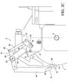
- FIG. 3 shows, in the same illustration as FIG. 1 , the embodiment according to FIG. 1 during the motion of the measuring head into the measuring position;
- FIGS. 4A and 4B show in a highly schematic illustration a first embodiment of a motorized drive unit according to the invention for adjusting the position of the stop in two positions of the stop;
- FIGS. 5A and 5B show, in the same illustration as FIG. 4 , a second embodiment of a motorized drive unit.
- FIG. 1 shows an embodiment of a measuring device 2 according to the invention which is used for the in-process measurement of test pieces during a machining operation on a grinding machine 4 .
- the grinding machine 4 which for simplicity is only partially illustrated, has a grinding wheel 8 which is rotatable about a rotational axis 6 fixed to the machine, and which is used for machining a test piece, which in the present embodiment is formed by a crank pin 10 of a crankshaft.
- the measuring device 2 has a measuring head 12 which is connected via a rod assembly or linkage 14 to a base body 18 of the measuring device 2 so as to be pivotable about a first pivot axis 16 .
- the measuring device 2 also has a means for pivoting the measuring head 12 in or out of the measuring position, as explained in greater detail below.
- the linkage 14 has a first rod assembly element or first linkage element 20 and a second rod assembly or linkage element 22 which are mounted so as to be pivotable about the first pivot axis 16 .
- a third rod assembly or linkage element 26 is connected which is pivotable about a second pivot axis 24 , and whose end facing away from the second pivot axis 24 is connected to a fourth rod assembly or linkage element so as to be pivotable about a third pivot axis 28 , the fourth rod assembly element being connected to the first rod assembly element 20 , at a distance from the third pivot axis 28 , so as to be pivotable about a fourth pivot axis.
- first rod assembly element 20 and the third rod assembly element 26 are provided in a nonparallel manner with respect to one another, the distance between the first pivot axis 16 and the second pivot axis 24 being smaller than the distance between the third pivot axis 28 and the fourth pivot axis 32 .
- the second rod assembly element 22 has a lever arm 34 such that the lever arm 34 together with the rod assembly element 22 forms a two-armed angle lever, whose function is explained in greater detail below.
- the measuring head 12 is provided on a holding arm 35 which is connected to the fourth rod assembly element 30 extending past the fourth pivot axis 32 .
- the connection between the holding arm 34 and the fourth rod assembly element 30 has a rigid configuration. It is apparent from FIG. 2A that in the illustrated embodiment a free end of the holding arm 34 which supports the measuring head 12 is angled toward the first pivot axis 16 , wherein a portion of the holding arm 34 connected to the fourth rod assembly element 30 together with the fourth rod assembly element 30 define an angle greater than 90°.
- the measuring head 12 has a linearly deflectable measuring probe 36 , indicated by a dashed line in FIG. 2A .
- the measuring head 12 also has a measuring prism 38 .
- the manner in which roundness and/or dimension measurements are performed on a test piece, in particular a crank pin of a crankshaft or another cylindrical component, using a system composed of a linearly deflectable measuring probe 36 and a measuring prism 38 is generally known to one skilled in the art and therefore is not explained in greater detail herein.
- the measuring device 2 also has a means for moving the measuring head 12 from a rest position into the measuring position, which in the present embodiment has a means for pivoting the measuring head 12 in and out which engages with the rod assembly 14 , as explained in greater detail with reference to FIG. 1 .
- the means for pivoting the measuring head 12 in and out has a pivot-in device 40 and a separate pivot-out device 42 .
- the pivot-in device 40 has a spring means, which in the present embodiment includes a spring 44 , configured as a compression spring, which acts on the measuring head 12 via the rod assembly 14 in a pivot-in direction represented by an arrow 46 in FIG. 1 .
- the spring 44 is configured as a compression spring, and at one end is supported on the base body 18 of the measuring device 2 and at the other end is supported on the lever arm 34 , so that the spring 44 acts on the lever arm 34 in the counterclockwise direction in FIG. 1 , and thus tends to move the measuring head 12 in the pivot-in direction 46 by means of the rod assembly 14 .
- the pivot-out device 42 in this embodiment has a hydraulic cylinder 48 , the piston of which is connected at its free end to the base body 18 of the measuring device 2 .
- the piston rod 50 of the hydraulic cylinder 48 is connected to a lever system 42 , in the present embodiment configured as a toggle lever, the free end of which facing away from the piston rod 50 is connected to a one-armed lever 54 , which is supported coaxially with the pivot axis 16 , in an eccentric manner with respect to the first pivot axis 16 .
- the lever 54 At its free end the lever 54 has a journal 56 , which extends into the plane of the drawing, and which loosely acts on the first rod assembly element 20 , so that for a motion in a pivot-out direction which corresponds to a clockwise motion in the drawing, the lever 54 functions as a carrier for the first rod assembly element 20 .
- a sensor means is provided which is in operative connection with a control means for controlling the pivot-in device 40 and the pivot-out device 42 .
- Measured values which are recorded by the measuring probe 36 during a measuring operation are evaluated using an evaluation computer.
- the manner in which corresponding measured values are evaluated is generally known to one skilled in the art and therefore is not explained in greater detail herein.
- the mode of functioning of the measuring device 2 according to the invention is as follows:
- the hydraulic cylinder 48 For pivoting the measuring head 12 in the pivot-in direction 46 , the hydraulic cylinder 48 is activated in such a way that its piston rod 50 travels to the right in FIG. 1 .
- the spring 44 presses against the lever arm 34 , so that the lever arm 34 is pivoted in the counterclockwise direction in FIG. 2 . Since the lever arm 34 is connected to the second rod assembly element 22 in a rotationally fixed manner, the second rod assembly element 22 and therefore the entire rod assembly 14 is pivoted in the counterclockwise direction in FIG. 2 .
- FIG. 2B shows the measuring head 12 in a position between the rest position and the measuring position.
- FIG. 2 C shows the measuring head 12 in a search position in which it is not yet in contact with the crank pin 10 .
- FIG. 2D shows the measuring head 12 in its measuring position, in which it is in contact with the crank pin 10 .
- FIG. 2E corresponds to FIG. 2C , the measuring head 12 being illustrated in its search position with respect to a crank pin 10 ′ of larger diameter.
- FIG. 3 shows the measuring device 2 in the search position of the measuring head 12 , which is also illustrated in FIG. 2C . It is apparent from a comparison of FIG. 1 and FIG. 3 that the lever 54 is pivoted in the counterclockwise direction in FIG. 1 by means of the lever system 42 when the piston rod 50 of the hydraulic cylinder 48 is extended, until the angular position of the lever 54 illustrated in FIG. 3 is reached. As shown in FIG. 1 and FIG. 3 that the lever 54 is pivoted in the counterclockwise direction in FIG. 1 by means of the lever system 42 when the piston rod 50 of the hydraulic cylinder 48 is extended, until the angular position of the lever 54 illustrated in FIG. 3 is reached. As shown in FIG.
- the journal 56 is provided at a distance from the first rod assembly element 20 in the circumferential direction of the first rotational axis 16 , so that the first rod assembly element 20 and therefore the entire rod assembly 14 is able to move freely under the effect of the weight of the measuring head 12 , including the holding arm 34 , and the pressure force exerted by the spring 44 .
- the measuring head 12 contacts the crank pin 10 , the measuring head following orbital rotations of the crank pin 10 about the crankshaft during the grinding operation.
- the base body 18 of the measuring device 2 is connected to a mounting of the grinding wheel 8 , in particular to a carriage of the grinding machine, in a fixed manner so that the measuring device 2 follows translatory motions of the grinding wheel 8 in the radial direction of the rotational axis 6 .
- the measuring probe 36 records measured values, on the basis of which the roundness and/or the diameter of the crank pin may be assessed in the evaluation computer downstream from the measuring probe 36 .
- the grinding wheel 8 is disengaged from the crank pin 10 .
- the control unit activates the hydraulic cylinder 48 in such a way that the piston rod 50 thereof moves to the left in FIG. 3 .
- This causes the lever 54 to be pivoted in the clockwise direction in FIG. 3 by means of the lever system 42 .
- the roller 56 is provided at a distance from the rod assembly element 20 in the circumferential direction of the first pivot axis 16 , the measuring head 12 initially remains in the measuring position. When the roller 56 comes into contact with the first rod assembly element 20 upon further pivoting of the lever 54 in the clockwise direction in FIG.
- the lever 54 functions as a carrier upon further pivoting in the clockwise direction and carries the first rod assembly element 20 , and therefore the entire rod assembly 14 , in the clockwise direction, so that the measuring head is pivoted out in the direction opposite the pivot-in direction 46 until the rest position illustrated in FIG. 1 is reached.
- the measuring head moves in the circumferential direction of the crank pin 10 with an angular stroke, which angular stroke in the illustrated embodiment is about ⁇ 7° and +5°, i.e., 12° total.
- a motorized drive unit 80 (see FIG. 4 ) is operatively associated with the stop 57 for adjusting the position of the stop 57 in such a way that the measuring position is adjustable.
- the measuring position is understood to mean the position in which the lever arm 34 comes to rest against the stop 57 , independently from the motion of the measuring head 12 together with the crank pin 10 after it engages with the crank pin.
- the drive unit is configured as a drive unit operated by an electric motor, and has a linear drive 82 having an electric motor 84 .
- the stop 57 is connected to one end of a one-armed lever 86 , the other end of which is mounted so as to be pivotable about a pivot axis 88 .
- the position of the stop 57 is adjusted by pivoting the lever 86 .
- an output element 92 which is linearly movable along a double arrow 90 , is articulatedly connected to one end of a rod 94 , the other end of which is articulatedly connected to the lever 86 at a distance from the pivot axis 88 and the stop 57 .
- a control unit 96 For activating the drive unit 80 , a control unit 96 is provided which may be in the form of a control computer, for example.
- an input unit 98 which is used by an operator of the measuring device 2 to manually enter the position of the stop 57 to be adjusted is associated on the one hand with the control unit 96 .
- the operator enters the desired or required position of the stop 57 via the input unit 98 .
- the control unit then activates the drive unit 80 in such a way that the stop 57 is moved into the selected position. It may be necessary to adjust the position of the stop 57 , for example, when a crank pin 10 having a larger diameter than that in FIG. 2A is to be measured, and in particular a larger measuring prism 38 is used for this purpose. In such a case, the position of the stop 57 may be adjusted by the operator, for example by entering the diameter of the crank pin to be measured or an identifier for the measuring prism 38 used. The control unit 96 then converts the diameter of the crank pin or the identifier for the measuring prism 38 to the associated position of the stop 57 and appropriately activates the drive unit 80 . In this regard, the position of the stop 57 is adjusted semi-automatically.
- control unit 96 is connected to an RFID reader, an RFID chip being associated with each measuring prism 38 used in conjunction with the measuring device 2 .
- the RFID reader reads, when the measuring device 2 is started, for example, the RFID chip associated with the measuring prism 38 used, and transmits the associated data to the control unit 96 , which determines the required position of the stop 57 and correspondingly activates the drive unit.
- control unit 96 the input unit 98 , and the RFID reader have been omitted in FIGS. 4B , 5 A, and 5 B.
- FIG. 4B shows the stop 57 in a position that is shifted with respect to FIG. 4A , with the lever 86 pivoted in the counterclockwise direction with respect to FIG. 4A , so that when the measuring head 12 pivots in, the lever arm 34 correspondingly comes to rest against the stop 57 at a later time.
- FIG. 5A shows a second embodiment of a drive unit 80 used according to the invention, which differs from the embodiment according to FIG. 4A in that the stop 57 is provided directly at the output element 92 of the linear drive 82 .
- the stop 57 is not pivoted, and instead is linearly displaced along the linear displacement axis of the output element 92 , and in the illustrated embodiment is displaced in height.
- FIG. 5B shows the embodiment according to FIG. 5A in a position in which the stop 57 is shifted downward in the drawing compared to FIG. 5A , so that in comparison to FIG. 5A the lever arm 34 comes to rest against the stop 57 at a correspondingly later time.
- the invention greatly increases the operational reliability of the measuring device 2 according to the invention, and is configured to make operation simpler and less time-consuming.
- FIGS. 2A through 2E show a variant which has a slightly modified configuration with respect to the embodiment according to FIG. 1 and FIG. 3 , which, however, is consistent with the embodiment according to FIG. 1 and FIG. 3 with regard to the basic principle of the invention.
Applications Claiming Priority (3)
| Application Number | Priority Date | Filing Date | Title |
|---|---|---|---|
| DE102010013069 | 2010-03-26 | ||
| DE102010013069.9-52 | 2010-03-26 | ||
| DE102010013069A DE102010013069B4 (de) | 2010-03-26 | 2010-03-26 | Meßvorrichtung |
Publications (2)
| Publication Number | Publication Date |
|---|---|
| US20110232117A1 US20110232117A1 (en) | 2011-09-29 |
| US8429829B2 true US8429829B2 (en) | 2013-04-30 |
Family
ID=44063330
Family Applications (1)
| Application Number | Title | Priority Date | Filing Date |
|---|---|---|---|
| US13/073,625 Active 2031-06-08 US8429829B2 (en) | 2010-03-26 | 2011-03-28 | Measuring device |
Country Status (4)
| Country | Link |
|---|---|
| US (1) | US8429829B2 (de) |
| EP (1) | EP2368667B1 (de) |
| CN (1) | CN102198635B (de) |
| DE (1) | DE102010013069B4 (de) |
Cited By (12)
| Publication number | Priority date | Publication date | Assignee | Title |
|---|---|---|---|---|
| US20120324747A1 (en) * | 1995-10-03 | 2012-12-27 | Dall Aglio Carlo | Method for checking the diameter of a cylindrical part in orbital motion |
| US20150285609A1 (en) * | 2014-04-07 | 2015-10-08 | Jtekt Corporation | Machine tool including affected layer detection sensor |
| US20160102959A1 (en) * | 2013-06-17 | 2016-04-14 | Marposs Societa' Per Azioni | Apparatus for checking dimensions and/or shape of a mechanical part |
| US9393663B2 (en) | 2010-08-23 | 2016-07-19 | Hommel-Etamic Gmbh | Measuring device |
| US9562756B2 (en) | 2012-09-20 | 2017-02-07 | Jenoptik Industrial Metrology Germany Gmbh | Measuring device with calibration |
| US20170082417A1 (en) * | 2015-09-17 | 2017-03-23 | Jenoptik Industrial Metrology Germany Gmbh | Roundness and/or dimension measuring device |
| US10408597B2 (en) | 2016-04-18 | 2019-09-10 | Jenoptik Industrial Metrology Germany Gmbh | Measuring assembly |
| US10480965B2 (en) | 2016-07-20 | 2019-11-19 | Jenoptik Industrial Metrology Germany Gmbh | Surface measuring device |
| US10760891B2 (en) | 2017-03-29 | 2020-09-01 | Jenoptik Industrial Metrology Germany Gmbh | Surface measuring apparatus |
| US10928177B2 (en) | 2018-02-15 | 2021-02-23 | Jenoptik Industrial Metrology Germany Gmbh | Measuring apparatus for surface or contour measurement |
| US11255653B2 (en) | 2018-12-19 | 2022-02-22 | Jenoptik Industrial Metrology Germany Gmbh | Method for operating a surface measurement apparatus |
| US11454487B2 (en) | 2019-05-07 | 2022-09-27 | Jenoptik Industrial Metrology Germany Gmbh | Surface measuring apparatus |
Families Citing this family (13)
| Publication number | Priority date | Publication date | Assignee | Title |
|---|---|---|---|---|
| DE102009032353A1 (de) * | 2009-07-08 | 2011-09-08 | Hommel-Etamic Gmbh | Verfahren zur Ermittlung der Form eines Werkstücks |
| DE102009042252B4 (de) * | 2009-09-22 | 2014-03-06 | Jenoptik Industrial Metrology Germany Gmbh | Meßvorrichtung |
| DE102010013069B4 (de) | 2010-03-26 | 2012-12-06 | Hommel-Etamic Gmbh | Meßvorrichtung |
| US20130115034A1 (en) * | 2011-11-08 | 2013-05-09 | Caterpillar Inc. | Pin position sensor mounting assembly |
| JP6071103B2 (ja) * | 2012-03-09 | 2017-02-01 | 株式会社ニデック | 眼鏡枠形状測定装置 |
| CN102672612B (zh) * | 2012-06-06 | 2014-07-02 | 贵阳险峰机床有限责任公司 | 用于数控轧辊磨床在线测量工件装置 |
| ES2731292T3 (es) * | 2013-09-16 | 2019-11-14 | Marposs Spa | Aparato para verificar las dimensiones diametrales de muñequillas |
| DE102013226733B4 (de) * | 2013-12-19 | 2021-12-23 | Erwin Junker Grinding Technology A.S. | VERFAHREN UND SCHLEIFMASCHINE ZUM MESSEN UND ERZEUGEN EINER AUßENSOLLKONTUR EINES WERKSTÜCKES DURCH SCHLEIFEN |
| DE202014011006U1 (de) * | 2014-09-24 | 2017-04-20 | Jenoptik Industrial Metrology Germany Gmbh | Messvorrichtung |
| JP6554964B2 (ja) * | 2015-07-21 | 2019-08-07 | 株式会社ジェイテクト | 研削盤 |
| JP6597012B2 (ja) * | 2015-07-21 | 2019-10-30 | 株式会社ジェイテクト | 研削盤 |
| IT201700088988A1 (it) | 2017-08-02 | 2019-02-02 | Marposs Spa | Apparecchiatura per il controllo di dimensioni diametrali di un perno in moto orbitale |
| DE102019104949A1 (de) | 2019-01-07 | 2020-07-09 | Jenoptik Industrial Metrology Germany Gmbh | Messkopf einer Messvorrichtung zur Formmessung an wellenartigen Werkstücken |
Citations (122)
| Publication number | Priority date | Publication date | Assignee | Title |
|---|---|---|---|---|
| US1425283A (en) | 1921-04-02 | 1922-08-08 | Frederick J Pratt | Grinding gauge |
| US1557903A (en) | 1921-04-18 | 1925-10-20 | Skf Svenska Kullagerfab Ab | Means for testing the progress of work in machines for grinding bodies of revolution |
| US1815049A (en) | 1927-07-08 | 1931-07-21 | Norton Co | Work size mechanism for grinding machines |
| US1892005A (en) | 1930-12-15 | 1932-12-27 | Int Harvester Co | Gauge |
| FR756177A (fr) | 1931-07-25 | 1933-12-06 | Norton Co | Perfectionnements aux machines à rectifier |
| US1941456A (en) * | 1928-08-23 | 1934-01-02 | Charles E Wisner | Grinding gauge |
| GB405817A (en) | 1932-03-12 | 1934-02-15 | Landis Tool Co | Gauging apparatus for grinding or abrading machines or like machine tools |
| US2408672A (en) | 1944-04-22 | 1946-10-01 | Materiel Automobile Sa Pour La | Apparatus for measuring or checking transverse dimensions |
| US2603043A (en) | 1947-07-18 | 1952-07-15 | Sarl Ets Gendron Freres | Gauge controlled grinding wheel feed mechanism |
| US2789354A (en) | 1949-01-21 | 1957-04-23 | Optical Gaging Prod Inc | Profile contour machine |
| US2909873A (en) | 1957-04-29 | 1959-10-27 | James C Fisk | Gauge support |
| US2949708A (en) | 1959-06-24 | 1960-08-23 | Cincinnati Milling Machine Co | Gage head for in-process gaging in machine tool |
| US3157971A (en) | 1963-02-07 | 1964-11-24 | Landis Tool Co | Size control device adaptable to different diameters |
| US3274693A (en) | 1965-02-04 | 1966-09-27 | Bendix Corp | Method and apparatus for roundness measurement |
| US3321869A (en) | 1964-07-13 | 1967-05-30 | Farrel Corp | Machine tool |
| US3352022A (en) | 1965-10-11 | 1967-11-14 | James C Fisk | Upright grinding gauge |
| US3352065A (en) | 1964-09-09 | 1967-11-14 | Henschel Werke A G | Machine for grinding crankshafts |
| US3386178A (en) | 1965-08-11 | 1968-06-04 | Philip S. Arnold | Grinding gage |
| US3603044A (en) | 1969-06-10 | 1971-09-07 | Litton Industries Inc | Gauge mechanism for grinding machines |
| US3648377A (en) | 1969-06-25 | 1972-03-14 | Bendix Corp | Sling roundness gage |
| DE2146360A1 (de) | 1970-09-18 | 1972-03-30 | Litton Industries Inc | Werkzeugmaschine zur programmierten Bearbeitung eines Werkstückes |
| US3663190A (en) | 1970-04-22 | 1972-05-16 | James C Fisk | Gauge support |
| US3688411A (en) | 1969-04-26 | 1972-09-05 | Toyoda Machine Works Ltd | Wide range dimension measuring apparatus |
| US3777441A (en) | 1971-06-03 | 1973-12-11 | Toyoda Machine Works Ltd | Grinding machine |
| US3793775A (en) | 1970-12-03 | 1974-02-26 | Toyoda Machine Works Ltd | Sizing device |
| US3802087A (en) | 1971-07-19 | 1974-04-09 | Inductosyn Corp | Measuring apparatus |
| GB1361275A (en) | 1970-07-22 | 1974-07-24 | Raiteri A | Diameter measuring device |
| US3863352A (en) | 1973-06-14 | 1975-02-04 | American Gage & Mach | Gaging apparatus with flow control mechanism |
| US3987552A (en) | 1974-07-01 | 1976-10-26 | Inductosyn Corporation | Measuring apparatus |
| US4106241A (en) | 1976-10-28 | 1978-08-15 | Fisk James C | Grinding gauge support |
| US4141149A (en) | 1976-09-30 | 1979-02-27 | Gravure Research Institute, Inc. | Portable comparator gage for measuring the relative deviation in the diameter of cylinders |
| US4175462A (en) | 1977-06-17 | 1979-11-27 | Simon Jonathan C | System for selection and phase control of humbucking coils in guitar pickups |
| US4176461A (en) | 1974-05-03 | 1979-12-04 | Spetsialnoe Knostruktorskoe Bjuro PO Proektirovaniju Shlifovalnogo Oborudovania | Device for measuring the deviation of object with nominally circular cross-section from the round shape |
| US4244110A (en) | 1978-07-20 | 1981-01-13 | The Warner & Swasey Company | Workpiece end locator |
| GB2086778A (en) | 1980-10-28 | 1982-05-19 | Landis Lund Ltd | Method and apparatus for indexing of a crankshaft |
| US4351115A (en) | 1979-04-05 | 1982-09-28 | Finike Italiana Marposs, S.P.A. | Apparatus for checking the linear dimensions of shafts |
| EP0068082A2 (de) | 1981-06-13 | 1983-01-05 | Dr. Johannes Heidenhain GmbH | Verfahren zur Messung der Rundheitsabweichungen von Rotations-körpern |
| US4414748A (en) | 1982-02-16 | 1983-11-15 | The Unites States Of America As Represented By The Department Of Energy | Ball mounting fixture for a roundness gage |
| US4429464A (en) | 1982-01-29 | 1984-02-07 | Burrus Brice M | Roundness calibration standard |
| US4437239A (en) | 1980-12-23 | 1984-03-20 | Finike Italiana Marposs S.P.A. | Gauge for the dimensional checking of a mechanical piece |
| US4480412A (en) | 1982-09-03 | 1984-11-06 | Litton Industrial Products, Inc. | In-process grinding gage |
| US4485593A (en) | 1981-05-30 | 1984-12-04 | Naxos-Union Schleifmittel Und Schleifmaschinenfabrik | Grinding machine for crankshaft pins |
| US4524546A (en) | 1983-06-06 | 1985-06-25 | Armco Inc | Roll profile gauge |
| GB2161101A (en) | 1984-07-03 | 1986-01-08 | Schaudt Maschinenbau Gmbh | Apparatus for monitoring the diameters of crankpins during treatment in grinding machines |
| US4596076A (en) | 1982-06-03 | 1986-06-24 | Meseltron S.A. | Device for handling a cylindrical or spherical piece |
| US4606130A (en) | 1984-01-13 | 1986-08-19 | Schaudt Maschinenbau Gmbh | Apparatus for monitoring the diameters and axial positions of workpieces in machine tools |
| US4625413A (en) | 1984-10-15 | 1986-12-02 | Finike Italiana Marposs S.P.A. | Head for checking dimensions of mechanical parts |
| US4637144A (en) * | 1984-07-03 | 1987-01-20 | Schaudt Maschinenbau Gmbh | Apparatus for monitoring the diameters of crankpins during treatment in grinding machines |
| US4651438A (en) | 1985-03-27 | 1987-03-24 | Hommelwerke Gmbh | Eccentricity measuring apparatus |
| US4679331A (en) | 1985-08-26 | 1987-07-14 | Ppg Industries, Inc. | Apparatus and method for determining contour characteristics of a contoured article |
| GB2197477A (en) | 1986-10-28 | 1988-05-18 | David Alun Armstrong | Diametral variation determination for workpieces |
| US4807400A (en) | 1986-03-20 | 1989-02-28 | Giustina International S.P.A. | Measuring apparatus for grinding machines for cylinders with structural and surface checking devices |
| US4819195A (en) | 1987-01-20 | 1989-04-04 | The Warner & Swasey Company | Method for calibrating a coordinate measuring machine and the like and system therefor |
| EP0322120A2 (de) | 1987-11-30 | 1989-06-28 | Btg International Limited | Verfahren und Vorrichtung zum Messen der Querdimensionen von Werkstücken |
| US4903413A (en) | 1986-02-07 | 1990-02-27 | Rank Taylor Hobson Limited | Surface profile measurement of workpieces |
| EP0382336A2 (de) | 1989-02-07 | 1990-08-16 | Industrial Metal Products Corporation | Grössenkontrollschuh für eine Feinstbearbeitungsmaschine |
| US4958442A (en) | 1988-08-19 | 1990-09-25 | J. M. Voith Gmbh | Measuring device, specifically for measuring the diameter of rolls on roll grinders |
| US4986004A (en) | 1989-01-04 | 1991-01-22 | Pat Messtechnik Gmbh | Method and apparatus for measuring the configuration of cylinder bores in workpieces |
| US5021650A (en) | 1989-03-29 | 1991-06-04 | Rsf-Elektronik Gesellschaft M.B.H. | Method of electronically correcting position errors in an incremental measuring system and measuring system for carrying out the method |
| US5054205A (en) | 1987-10-09 | 1991-10-08 | Marposs Societa' Per Azioni | Wide range apparatus for checking linear dimensions of parts |
| US5058325A (en) | 1988-09-27 | 1991-10-22 | Societe Procedes Machines Speciales, S.P.M.S. | Machine for the abrasive machining of cylindrical journals on components, in particular for machining journals and crank pins on crankshafts using abrasive material |
| US5077908A (en) | 1987-11-04 | 1992-01-07 | David Moore | Apparatus for measuring the roundness of a surface of an object |
| EP0469439A1 (de) | 1990-08-02 | 1992-02-05 | Meseltron S.A. | Vorrichtung zum Messen des Durchmessers von zylindrischen Werkstücken während der Bearbeitung |
| US5086569A (en) | 1987-11-09 | 1992-02-11 | Marposs Societa' Per Azioni | Apparatus for checking dimensions of workpieces |
| US5088207A (en) | 1989-12-13 | 1992-02-18 | Betsill Harry E | True end-to-end electronic saddle micrometer |
| US5095634A (en) | 1988-12-09 | 1992-03-17 | Pietzsch Automatisierungstechnik Gmbh | Instrument for simultaneously measuring a succession of cylinder bores |
| US5097602A (en) | 1990-07-09 | 1992-03-24 | Westinghouse Electric Corp. | Apparatus and method for automated inspection of a surface contour on a workpiece |
| US5099585A (en) | 1991-02-19 | 1992-03-31 | Control Gaging, Inc. | In-process machine gage |
| EP0480222A2 (de) | 1990-10-06 | 1992-04-15 | FEINPRÜF PERTHEN GmbH | Induktiver Längenmesstaster |
| US5123173A (en) | 1988-08-11 | 1992-06-23 | Marposs Societa' Per Azioni | Apparatus for checking features of parts |
| US5136527A (en) | 1990-10-05 | 1992-08-04 | Precision Devices, Inc. | Surface finish measuring device and method for gear teeth |
| US5337485A (en) | 1992-01-28 | 1994-08-16 | Chien An Y | Roundness error and crown electronic measuring system |
| US5419056A (en) | 1993-07-29 | 1995-05-30 | Thomas E. Breitenstein | Centerless gaging apparatus for checking the concentricity and straightness of shank-type tools and the like |
| US5479096A (en) | 1994-08-08 | 1995-12-26 | Lucas Industries, Inc. | Analog sensing system with digital temperature and measurement gain and offset correction |
| DE4419656C2 (de) | 1994-06-06 | 1996-05-15 | Naxos Union Schleifmittel | Einrichtung zur Durchmesser- und/oder Rundheitsmessung beim exzentrischen Rundschleifen |
| US5542188A (en) | 1994-06-09 | 1996-08-06 | Zeiss Messgeratebau GmbH | Measuring apparatus for checking the dimensions of cylindrical workpieces |
| US5551814A (en) | 1992-11-05 | 1996-09-03 | Kabushiki Kaisha Komatsu Seisakusho | Crankshaft milling machine control system |
| US5551906A (en) | 1994-11-23 | 1996-09-03 | Voith Sulzer Paper Technology North America Inc. | Caliper assembly for grinder |
| GB2300582A (en) | 1995-05-06 | 1996-11-13 | Western Atlas Uk Ltd | Gauging the diameter of eccentric cylindrical workpieces |
| EP0810067A1 (de) | 1996-05-31 | 1997-12-03 | Toshiba Kikai Kabushiki Kaisha | Verfahren und Gerät zum Messen des Durchmessers einer Walze in einer Walzenschleifmaschine |
| DE29722951U1 (de) | 1996-12-31 | 1998-02-19 | Daewoo Heavy Ind Co Ltd | Werkzeugpositionsdetektor für eine Drehbank |
| US5758431A (en) | 1993-01-21 | 1998-06-02 | Marposs Societa' Per Azioni | Apparatus for checking geometrical features of pieces with rotational symmetry |
| EP0859689A1 (de) | 1995-10-03 | 1998-08-26 | Marposs Societa' Per Azioni | Vorrichtung zur prüfung des durchmessers von kurbelwellenzapfen rotierend mit einer orbitalen bewegung |
| DE4412682C2 (de) | 1994-04-13 | 1998-09-03 | Doerries Scharmann Ag I K | Vorrichtung zum Vermessen exzentrisch umlaufender Werkstücke |
| EP0878704A1 (de) | 1997-05-13 | 1998-11-18 | Gretag-Macbeth AG | Remissionsmessvorrichtung |
| EP0903199A2 (de) | 1997-09-23 | 1999-03-24 | Unova U.K. Limited | Verbesserungen an oder in Bezug auf Messen |
| US5902925A (en) | 1996-07-01 | 1999-05-11 | Integrated Sensor Solutions | System and method for high accuracy calibration of a sensor for offset and sensitivity variation with temperature |
| US5914593A (en) | 1993-06-21 | 1999-06-22 | Micro Strain Company, Inc. | Temperature gradient compensation circuit |
| US5919081A (en) | 1996-09-04 | 1999-07-06 | Unova Ip Corporation | Method and apparatus for computer numerically controlled pin grinder gauge |
| US5956659A (en) | 1997-03-26 | 1999-09-21 | Johannes Heidenhain Gmbh | Arrangement and method for the automatic correction of error-containing scanning signals of incremental position-measuring devices |
| US6029363A (en) | 1998-04-03 | 2000-02-29 | Mitutoyo Corporation | Self-calibrating position transducer system and method |
| US6062948A (en) | 1996-04-19 | 2000-05-16 | Schmitt Measurement Systems, Inc. | Apparatus and method for gauging a workpiece |
| US6088924A (en) | 1995-10-06 | 2000-07-18 | Etamic Sa | Machine for grinding a cylindrical piece in orbital motion |
| US6116269A (en) | 1998-07-07 | 2000-09-12 | Fasco Controls Corporation | Solenoid pressure transducer |
| US6159074A (en) | 1999-01-07 | 2000-12-12 | Kube; Samuel C. | Caliper assembly for a grinding machine |
| EP1063052A2 (de) | 1999-06-25 | 2000-12-27 | Toyoda Koki Kabushiki Kaisha | Vorrichtung zum Erfassen von Dimensionsfehlern von exzentrischen Zylindern durch Anwendung einem in Kontakt solch einem exzentrischen Zylinder gehaltenes Messgerät |
| US6167634B1 (en) | 1998-03-28 | 2001-01-02 | Snu Precision Co., Ltd. | Measurement and compensation system for thermal errors in machine tools |
| GB0105627D0 (en) | 2001-03-07 | 2001-04-25 | Cipla Ltd | Preparation of phthalanes |
| US6256898B1 (en) | 1998-03-31 | 2001-07-10 | Balance Systems S.P.A. | Workpiece-measuring apparatus, in particular for grinding machines |
| US6266570B1 (en) | 1996-01-24 | 2001-07-24 | Siemens Ag | Method for determination and optimization of an operating accuracy of a machine tool, a robot or the like |
| US6304827B1 (en) | 1999-09-16 | 2001-10-16 | Sensonor Asa | Sensor calibration |
| US6321171B1 (en) | 1998-04-03 | 2001-11-20 | Tektronix, Inc. | Electronic measurement instrument probe accessory offset, gain, and linearity correction method |
| US20020066179A1 (en) | 2000-12-01 | 2002-06-06 | Hall Hendley W. | System and method for metalization of deep vias |
| US6415200B1 (en) | 1992-02-14 | 2002-07-02 | Toyota Jidosha Kabushiki Kaisha | Apparatus and method for feedback-adjusting working condition for improving dimensional accuracy of processed workpieces |
| US6430832B1 (en) | 2000-01-18 | 2002-08-13 | Marposs Societa' Per Azioni | Apparatus for the in-process dimensional checking of cylindrical parts |
| US20020155790A1 (en) | 2001-04-19 | 2002-10-24 | Toyoda Koki Kabushiki Kaisha | Method and apparatus for grinding eccentric cylindrical portions of workpiece with diameter measuring device |
| WO2002090047A1 (en) | 2001-05-07 | 2002-11-14 | Marposs Società per Azioni | Apparatus for the diameter checking of eccentric portions of a mechanical piece in the course of the machining in a grinding machine |
| US6487787B1 (en) | 2001-08-03 | 2002-12-03 | Mitutoyo Corporation | System and method for determination of error parameters for performing self-calibration and other functions without an external position reference in a transducer |
| US6487896B1 (en) | 1998-03-13 | 2002-12-03 | Marposs Societa' Per Azioni | Head, system and method for the linear dimension checking of a mechanical piece |
| US6490912B1 (en) | 1999-11-02 | 2002-12-10 | Hommelwerke Gmbh | Probe for sensing the characteristics of a surface of a workpiece |
| US20030009895A1 (en) | 2000-03-06 | 2003-01-16 | Dall'aglio Carlo | Apparatus and methods for measuring the pin diameter of a crankshaft at the place of grinding |
| US20030056386A1 (en) | 2000-03-06 | 2003-03-27 | Franco Danielli | Apparatus and method to measure the dimensional and form deviation of crankpins at the place of grinding |
| US6560890B1 (en) | 2002-02-21 | 2003-05-13 | General Electric Company | Fixture for locating and clamping a part for laser drilling |
| US6568096B1 (en) | 1999-02-22 | 2003-05-27 | Obschestvo s Ogranichennoi Otvetctvennostju “Tekhnomash” | Device and method for measuring shape deviations of a cylindrical workpiece and correcting steadying element and correcting follower for use therewith |
| US6645047B1 (en) | 2000-03-20 | 2003-11-11 | Control Gaging, Inc. | Automatic gage head positioning system |
| US20040055172A1 (en) * | 2001-03-02 | 2004-03-25 | Franco Danielli | Apparatus for checking dimensional and geometrical features of pins |
| US6711829B2 (en) | 2000-09-29 | 2004-03-30 | Toyoda Koki Kabushiki Kaisha | Method for measuring work portion and machining method |
| US20050217130A1 (en) | 2002-06-12 | 2005-10-06 | Franco Danielli | Apparatus for checking the dimensional and geometric features of pins |
| DE102008016228A1 (de) | 2008-03-27 | 2009-10-08 | Hollinger Maschinen Gmbh | Eckenverputzmaschine sowie Verfahren zum Bearbeiten von Ecken eines verschweißten Profilrahmens |
| US7665222B2 (en) | 2006-02-16 | 2010-02-23 | Marposs Societa' Per Azioni | Gauge for checking radial dimensions of mechanical pieces |
| US20110119943A1 (en) | 2009-09-22 | 2011-05-26 | Yan Arnold | Measuring device |
| US20110232117A1 (en) | 2010-03-26 | 2011-09-29 | Hommel-Etamic Gmbh | Measuring device |
Family Cites Families (6)
| Publication number | Priority date | Publication date | Assignee | Title |
|---|---|---|---|---|
| US3321669A (en) * | 1964-04-13 | 1967-05-23 | Westinghouse Electric Corp | Time delay circuit using thermistors |
| JPH0752828B2 (ja) * | 1989-06-19 | 1995-06-05 | 株式会社日立製作所 | 半導体素子の駆動方法 |
| SE469135B (sv) * | 1991-09-25 | 1993-05-17 | Expandi Systems Ab | Anordning vid laensa |
| JP2001269864A (ja) * | 2000-03-24 | 2001-10-02 | Toyoda Mach Works Ltd | 半径測定式定寸装置を備えた工作機械 |
| JP3939959B2 (ja) * | 2001-10-24 | 2007-07-04 | 株式会社日平トヤマ | クランクシャフト加工機のピン径測定方法 |
| KR101486889B1 (ko) * | 2006-12-27 | 2015-01-28 | 마코 서지컬 코포레이션 | 공간 내에 조절가능한 포지티브 스톱을 제공하기 위한 장치 및 방법 |
-
2010
- 2010-03-26 DE DE102010013069A patent/DE102010013069B4/de not_active Expired - Fee Related
-
2011
- 2011-03-01 EP EP11001656.5A patent/EP2368667B1/de active Active
- 2011-03-25 CN CN201110072993XA patent/CN102198635B/zh not_active Expired - Fee Related
- 2011-03-28 US US13/073,625 patent/US8429829B2/en active Active
Patent Citations (161)
| Publication number | Priority date | Publication date | Assignee | Title |
|---|---|---|---|---|
| US1425283A (en) | 1921-04-02 | 1922-08-08 | Frederick J Pratt | Grinding gauge |
| US1557903A (en) | 1921-04-18 | 1925-10-20 | Skf Svenska Kullagerfab Ab | Means for testing the progress of work in machines for grinding bodies of revolution |
| US1815049A (en) | 1927-07-08 | 1931-07-21 | Norton Co | Work size mechanism for grinding machines |
| US1941456A (en) * | 1928-08-23 | 1934-01-02 | Charles E Wisner | Grinding gauge |
| US1892005A (en) | 1930-12-15 | 1932-12-27 | Int Harvester Co | Gauge |
| FR756177A (fr) | 1931-07-25 | 1933-12-06 | Norton Co | Perfectionnements aux machines à rectifier |
| GB405817A (en) | 1932-03-12 | 1934-02-15 | Landis Tool Co | Gauging apparatus for grinding or abrading machines or like machine tools |
| US2408672A (en) | 1944-04-22 | 1946-10-01 | Materiel Automobile Sa Pour La | Apparatus for measuring or checking transverse dimensions |
| US2603043A (en) | 1947-07-18 | 1952-07-15 | Sarl Ets Gendron Freres | Gauge controlled grinding wheel feed mechanism |
| US2789354A (en) | 1949-01-21 | 1957-04-23 | Optical Gaging Prod Inc | Profile contour machine |
| US2909873A (en) | 1957-04-29 | 1959-10-27 | James C Fisk | Gauge support |
| US2949708A (en) | 1959-06-24 | 1960-08-23 | Cincinnati Milling Machine Co | Gage head for in-process gaging in machine tool |
| US3157971A (en) | 1963-02-07 | 1964-11-24 | Landis Tool Co | Size control device adaptable to different diameters |
| US3321869A (en) | 1964-07-13 | 1967-05-30 | Farrel Corp | Machine tool |
| US3352065A (en) | 1964-09-09 | 1967-11-14 | Henschel Werke A G | Machine for grinding crankshafts |
| US3274693A (en) | 1965-02-04 | 1966-09-27 | Bendix Corp | Method and apparatus for roundness measurement |
| US3386178A (en) | 1965-08-11 | 1968-06-04 | Philip S. Arnold | Grinding gage |
| US3352022A (en) | 1965-10-11 | 1967-11-14 | James C Fisk | Upright grinding gauge |
| US3688411A (en) | 1969-04-26 | 1972-09-05 | Toyoda Machine Works Ltd | Wide range dimension measuring apparatus |
| US3603044A (en) | 1969-06-10 | 1971-09-07 | Litton Industries Inc | Gauge mechanism for grinding machines |
| US3648377A (en) | 1969-06-25 | 1972-03-14 | Bendix Corp | Sling roundness gage |
| US3663190A (en) | 1970-04-22 | 1972-05-16 | James C Fisk | Gauge support |
| GB1361275A (en) | 1970-07-22 | 1974-07-24 | Raiteri A | Diameter measuring device |
| US3694970A (en) | 1970-09-18 | 1972-10-03 | Litton Industries Inc | Offset size adjustment circuit for grinding machines |
| DE2146360A1 (de) | 1970-09-18 | 1972-03-30 | Litton Industries Inc | Werkzeugmaschine zur programmierten Bearbeitung eines Werkstückes |
| GB1362996A (en) | 1970-09-18 | 1974-08-14 | Litton Industries Inc | Machine tools |
| US3793775A (en) | 1970-12-03 | 1974-02-26 | Toyoda Machine Works Ltd | Sizing device |
| US3777441A (en) | 1971-06-03 | 1973-12-11 | Toyoda Machine Works Ltd | Grinding machine |
| US3802087A (en) | 1971-07-19 | 1974-04-09 | Inductosyn Corp | Measuring apparatus |
| US3863352A (en) | 1973-06-14 | 1975-02-04 | American Gage & Mach | Gaging apparatus with flow control mechanism |
| US4176461A (en) | 1974-05-03 | 1979-12-04 | Spetsialnoe Knostruktorskoe Bjuro PO Proektirovaniju Shlifovalnogo Oborudovania | Device for measuring the deviation of object with nominally circular cross-section from the round shape |
| US3987552A (en) | 1974-07-01 | 1976-10-26 | Inductosyn Corporation | Measuring apparatus |
| US4141149A (en) | 1976-09-30 | 1979-02-27 | Gravure Research Institute, Inc. | Portable comparator gage for measuring the relative deviation in the diameter of cylinders |
| US4106241A (en) | 1976-10-28 | 1978-08-15 | Fisk James C | Grinding gauge support |
| US4175462A (en) | 1977-06-17 | 1979-11-27 | Simon Jonathan C | System for selection and phase control of humbucking coils in guitar pickups |
| US4244110A (en) | 1978-07-20 | 1981-01-13 | The Warner & Swasey Company | Workpiece end locator |
| US4351115A (en) | 1979-04-05 | 1982-09-28 | Finike Italiana Marposs, S.P.A. | Apparatus for checking the linear dimensions of shafts |
| GB2086778A (en) | 1980-10-28 | 1982-05-19 | Landis Lund Ltd | Method and apparatus for indexing of a crankshaft |
| US4437239A (en) | 1980-12-23 | 1984-03-20 | Finike Italiana Marposs S.P.A. | Gauge for the dimensional checking of a mechanical piece |
| US4485593A (en) | 1981-05-30 | 1984-12-04 | Naxos-Union Schleifmittel Und Schleifmaschinenfabrik | Grinding machine for crankshaft pins |
| EP0068082A2 (de) | 1981-06-13 | 1983-01-05 | Dr. Johannes Heidenhain GmbH | Verfahren zur Messung der Rundheitsabweichungen von Rotations-körpern |
| US4429464A (en) | 1982-01-29 | 1984-02-07 | Burrus Brice M | Roundness calibration standard |
| US4414748A (en) | 1982-02-16 | 1983-11-15 | The Unites States Of America As Represented By The Department Of Energy | Ball mounting fixture for a roundness gage |
| US4596076A (en) | 1982-06-03 | 1986-06-24 | Meseltron S.A. | Device for handling a cylindrical or spherical piece |
| US4480412A (en) | 1982-09-03 | 1984-11-06 | Litton Industrial Products, Inc. | In-process grinding gage |
| US4524546A (en) | 1983-06-06 | 1985-06-25 | Armco Inc | Roll profile gauge |
| US4606130A (en) | 1984-01-13 | 1986-08-19 | Schaudt Maschinenbau Gmbh | Apparatus for monitoring the diameters and axial positions of workpieces in machine tools |
| GB2161101A (en) | 1984-07-03 | 1986-01-08 | Schaudt Maschinenbau Gmbh | Apparatus for monitoring the diameters of crankpins during treatment in grinding machines |
| US4637144A (en) * | 1984-07-03 | 1987-01-20 | Schaudt Maschinenbau Gmbh | Apparatus for monitoring the diameters of crankpins during treatment in grinding machines |
| US4625413A (en) | 1984-10-15 | 1986-12-02 | Finike Italiana Marposs S.P.A. | Head for checking dimensions of mechanical parts |
| US4651438A (en) | 1985-03-27 | 1987-03-24 | Hommelwerke Gmbh | Eccentricity measuring apparatus |
| US4679331A (en) | 1985-08-26 | 1987-07-14 | Ppg Industries, Inc. | Apparatus and method for determining contour characteristics of a contoured article |
| US4903413A (en) | 1986-02-07 | 1990-02-27 | Rank Taylor Hobson Limited | Surface profile measurement of workpieces |
| US4807400A (en) | 1986-03-20 | 1989-02-28 | Giustina International S.P.A. | Measuring apparatus for grinding machines for cylinders with structural and surface checking devices |
| GB2197477A (en) | 1986-10-28 | 1988-05-18 | David Alun Armstrong | Diametral variation determination for workpieces |
| US4819195A (en) | 1987-01-20 | 1989-04-04 | The Warner & Swasey Company | Method for calibrating a coordinate measuring machine and the like and system therefor |
| US5054205A (en) | 1987-10-09 | 1991-10-08 | Marposs Societa' Per Azioni | Wide range apparatus for checking linear dimensions of parts |
| US5077908A (en) | 1987-11-04 | 1992-01-07 | David Moore | Apparatus for measuring the roundness of a surface of an object |
| US5086569A (en) | 1987-11-09 | 1992-02-11 | Marposs Societa' Per Azioni | Apparatus for checking dimensions of workpieces |
| EP0322120A2 (de) | 1987-11-30 | 1989-06-28 | Btg International Limited | Verfahren und Vorrichtung zum Messen der Querdimensionen von Werkstücken |
| US5123173A (en) | 1988-08-11 | 1992-06-23 | Marposs Societa' Per Azioni | Apparatus for checking features of parts |
| US4958442A (en) | 1988-08-19 | 1990-09-25 | J. M. Voith Gmbh | Measuring device, specifically for measuring the diameter of rolls on roll grinders |
| US5058325A (en) | 1988-09-27 | 1991-10-22 | Societe Procedes Machines Speciales, S.P.M.S. | Machine for the abrasive machining of cylindrical journals on components, in particular for machining journals and crank pins on crankshafts using abrasive material |
| US5095634A (en) | 1988-12-09 | 1992-03-17 | Pietzsch Automatisierungstechnik Gmbh | Instrument for simultaneously measuring a succession of cylinder bores |
| US4986004A (en) | 1989-01-04 | 1991-01-22 | Pat Messtechnik Gmbh | Method and apparatus for measuring the configuration of cylinder bores in workpieces |
| EP0382336A2 (de) | 1989-02-07 | 1990-08-16 | Industrial Metal Products Corporation | Grössenkontrollschuh für eine Feinstbearbeitungsmaschine |
| US5021650A (en) | 1989-03-29 | 1991-06-04 | Rsf-Elektronik Gesellschaft M.B.H. | Method of electronically correcting position errors in an incremental measuring system and measuring system for carrying out the method |
| US5088207A (en) | 1989-12-13 | 1992-02-18 | Betsill Harry E | True end-to-end electronic saddle micrometer |
| US5097602A (en) | 1990-07-09 | 1992-03-24 | Westinghouse Electric Corp. | Apparatus and method for automated inspection of a surface contour on a workpiece |
| US5150545A (en) | 1990-08-02 | 1992-09-29 | Meseltron S.A. | Arrangement for measuring the diameter of cylindrical parts during the machining thereof |
| EP0469439A1 (de) | 1990-08-02 | 1992-02-05 | Meseltron S.A. | Vorrichtung zum Messen des Durchmessers von zylindrischen Werkstücken während der Bearbeitung |
| US5136527A (en) | 1990-10-05 | 1992-08-04 | Precision Devices, Inc. | Surface finish measuring device and method for gear teeth |
| EP0480222A2 (de) | 1990-10-06 | 1992-04-15 | FEINPRÜF PERTHEN GmbH | Induktiver Längenmesstaster |
| US5099585A (en) | 1991-02-19 | 1992-03-31 | Control Gaging, Inc. | In-process machine gage |
| US5337485A (en) | 1992-01-28 | 1994-08-16 | Chien An Y | Roundness error and crown electronic measuring system |
| US6415200B1 (en) | 1992-02-14 | 2002-07-02 | Toyota Jidosha Kabushiki Kaisha | Apparatus and method for feedback-adjusting working condition for improving dimensional accuracy of processed workpieces |
| US5551814A (en) | 1992-11-05 | 1996-09-03 | Kabushiki Kaisha Komatsu Seisakusho | Crankshaft milling machine control system |
| US5758431A (en) | 1993-01-21 | 1998-06-02 | Marposs Societa' Per Azioni | Apparatus for checking geometrical features of pieces with rotational symmetry |
| US5914593A (en) | 1993-06-21 | 1999-06-22 | Micro Strain Company, Inc. | Temperature gradient compensation circuit |
| US5419056A (en) | 1993-07-29 | 1995-05-30 | Thomas E. Breitenstein | Centerless gaging apparatus for checking the concentricity and straightness of shank-type tools and the like |
| DE4412682C2 (de) | 1994-04-13 | 1998-09-03 | Doerries Scharmann Ag I K | Vorrichtung zum Vermessen exzentrisch umlaufender Werkstücke |
| DE4419656C2 (de) | 1994-06-06 | 1996-05-15 | Naxos Union Schleifmittel | Einrichtung zur Durchmesser- und/oder Rundheitsmessung beim exzentrischen Rundschleifen |
| US5542188A (en) | 1994-06-09 | 1996-08-06 | Zeiss Messgeratebau GmbH | Measuring apparatus for checking the dimensions of cylindrical workpieces |
| US5479096A (en) | 1994-08-08 | 1995-12-26 | Lucas Industries, Inc. | Analog sensing system with digital temperature and measurement gain and offset correction |
| US5551906A (en) | 1994-11-23 | 1996-09-03 | Voith Sulzer Paper Technology North America Inc. | Caliper assembly for grinder |
| GB2300582A (en) | 1995-05-06 | 1996-11-13 | Western Atlas Uk Ltd | Gauging the diameter of eccentric cylindrical workpieces |
| US5761821A (en) | 1995-05-06 | 1998-06-09 | Western Atlas U.K. Limited | Gauging the diameter of eccentric cylindrical workpiece parts |
| US6298571B1 (en) | 1995-10-03 | 2001-10-09 | Marpos Societa' Per Azioni | Apparatus for checking diametral dimensions of rotating cylindrical parts |
| US7607239B2 (en) | 1995-10-03 | 2009-10-27 | Marposs, Societá per Azioni | Apparatus for checking diametral dimensions of cylindrical parts rotating with an orbital motion |
| EP0859689A1 (de) | 1995-10-03 | 1998-08-26 | Marposs Societa' Per Azioni | Vorrichtung zur prüfung des durchmessers von kurbelwellenzapfen rotierend mit einer orbitalen bewegung |
| US20100000109A1 (en) * | 1995-10-03 | 2010-01-07 | Dall Aglio Carlo | Apparatus for checking diametral dimensions of a rotating cylindrical part during a grinding thereof |
| US7954253B2 (en) * | 1995-10-03 | 2011-06-07 | Marposs Societa' Per Azioni | Apparatus for checking diametral dimensions of a rotating cylindrical part during a grinding thereof |
| US6067721A (en) | 1995-10-03 | 2000-05-30 | Marposs Societa' Per Azioni | Apparatus for checking the diameter of crankpins rotating with an orbital motion |
| US20020020075A1 (en) | 1995-10-03 | 2002-02-21 | Dall'aglio Carlo | Apparatus for checking diametral dimensions of cylindrical parts rotating with an orbital motion |
| EP0859689B1 (de) | 1995-10-03 | 1999-11-24 | Marposs Societa' Per Azioni | Vorrichtung zur prüfung des durchmessers von kurbelwellenzapfen rotierend mit einer orbitalen bewegung |
| US20110239478A1 (en) * | 1995-10-03 | 2011-10-06 | Dall Aglio Carlo | Apparatus for checking diametral dimensions of a rotating cylindrical part during a grinding thereof |
| US6088924A (en) | 1995-10-06 | 2000-07-18 | Etamic Sa | Machine for grinding a cylindrical piece in orbital motion |
| US6266570B1 (en) | 1996-01-24 | 2001-07-24 | Siemens Ag | Method for determination and optimization of an operating accuracy of a machine tool, a robot or the like |
| US6062948A (en) | 1996-04-19 | 2000-05-16 | Schmitt Measurement Systems, Inc. | Apparatus and method for gauging a workpiece |
| US5771599A (en) | 1996-05-31 | 1998-06-30 | Toshiba Kikai Kabushiki Kaisha | Method of and instrument for measuring roll diameter in roll grinder |
| EP0810067A1 (de) | 1996-05-31 | 1997-12-03 | Toshiba Kikai Kabushiki Kaisha | Verfahren und Gerät zum Messen des Durchmessers einer Walze in einer Walzenschleifmaschine |
| US5902925A (en) | 1996-07-01 | 1999-05-11 | Integrated Sensor Solutions | System and method for high accuracy calibration of a sensor for offset and sensitivity variation with temperature |
| US5919081A (en) | 1996-09-04 | 1999-07-06 | Unova Ip Corporation | Method and apparatus for computer numerically controlled pin grinder gauge |
| DE29722951U1 (de) | 1996-12-31 | 1998-02-19 | Daewoo Heavy Ind Co Ltd | Werkzeugpositionsdetektor für eine Drehbank |
| US5956659A (en) | 1997-03-26 | 1999-09-21 | Johannes Heidenhain Gmbh | Arrangement and method for the automatic correction of error-containing scanning signals of incremental position-measuring devices |
| US5982501A (en) | 1997-05-13 | 1999-11-09 | Gretag-Macbeth Ag | Reflectance measuring device |
| EP0878704A1 (de) | 1997-05-13 | 1998-11-18 | Gretag-Macbeth AG | Remissionsmessvorrichtung |
| DE69809667T2 (de) | 1997-09-23 | 2003-04-24 | Unova Uk Ltd | Verbesserungen an oder in Bezug auf Messen |
| EP0903199A2 (de) | 1997-09-23 | 1999-03-24 | Unova U.K. Limited | Verbesserungen an oder in Bezug auf Messen |
| US6487896B1 (en) | 1998-03-13 | 2002-12-03 | Marposs Societa' Per Azioni | Head, system and method for the linear dimension checking of a mechanical piece |
| US6167634B1 (en) | 1998-03-28 | 2001-01-02 | Snu Precision Co., Ltd. | Measurement and compensation system for thermal errors in machine tools |
| US6256898B1 (en) | 1998-03-31 | 2001-07-10 | Balance Systems S.P.A. | Workpiece-measuring apparatus, in particular for grinding machines |
| US6321171B1 (en) | 1998-04-03 | 2001-11-20 | Tektronix, Inc. | Electronic measurement instrument probe accessory offset, gain, and linearity correction method |
| US6029363A (en) | 1998-04-03 | 2000-02-29 | Mitutoyo Corporation | Self-calibrating position transducer system and method |
| US6116269A (en) | 1998-07-07 | 2000-09-12 | Fasco Controls Corporation | Solenoid pressure transducer |
| US6159074A (en) | 1999-01-07 | 2000-12-12 | Kube; Samuel C. | Caliper assembly for a grinding machine |
| US6568096B1 (en) | 1999-02-22 | 2003-05-27 | Obschestvo s Ogranichennoi Otvetctvennostju “Tekhnomash” | Device and method for measuring shape deviations of a cylindrical workpiece and correcting steadying element and correcting follower for use therewith |
| EP1063052A2 (de) | 1999-06-25 | 2000-12-27 | Toyoda Koki Kabushiki Kaisha | Vorrichtung zum Erfassen von Dimensionsfehlern von exzentrischen Zylindern durch Anwendung einem in Kontakt solch einem exzentrischen Zylinder gehaltenes Messgerät |
| EP1063052B1 (de) | 1999-06-25 | 2004-11-10 | Toyoda Koki Kabushiki Kaisha | Vorrichtung zum Erfassen von Dimensionsfehlern von exzentrischen Zylindern durch Anwendung einem in Kontakt solch einem exzentrischen Zylinder gehaltenes Messgerät |
| DE60015654T2 (de) | 1999-06-25 | 2005-08-11 | Toyoda Koki K.K., Kariya | Vorrichtung zum Erfassen von Dimensionsfehlern von exzentrischen Zylindern durch Anwendung einem in Kontakt solch einem exzentrischen Zylinder gehaltenes Messgerät |
| US6304827B1 (en) | 1999-09-16 | 2001-10-16 | Sensonor Asa | Sensor calibration |
| US6490912B1 (en) | 1999-11-02 | 2002-12-10 | Hommelwerke Gmbh | Probe for sensing the characteristics of a surface of a workpiece |
| US6430832B1 (en) | 2000-01-18 | 2002-08-13 | Marposs Societa' Per Azioni | Apparatus for the in-process dimensional checking of cylindrical parts |
| US20040045181A1 (en) | 2000-01-18 | 2004-03-11 | Dall'aglio Carlo | Apparatus for the in-process dimensional checking of orbitally rotating crankpins |
| US7690127B2 (en) | 2000-01-18 | 2010-04-06 | Marposs, S.P.A. | Apparatus for the dimensional checking of an orbitally rotating crankpin of a crankshaft |
| US7464482B2 (en) | 2000-01-18 | 2008-12-16 | Marposs, S.P.A. | Apparatus for the dimensional checking of orbitally rotating pins |
| EP1118833B1 (de) | 2000-01-18 | 2009-07-15 | Marposs Societa' Per Azioni | Apparat zum Prüfen der Abmessung von zylindrischen Teilen |
| US6643943B2 (en) * | 2000-01-18 | 2003-11-11 | Marposs Societa' Per Azioni | Apparatus for the in-process dimensional checking of orbitally rotating crankpins |
| US20080155848A1 (en) | 2000-01-18 | 2008-07-03 | Dall Aglio Carlo | Apparatus for the dimensional checking of orbitally rotating pins |
| US20090113736A1 (en) | 2000-01-18 | 2009-05-07 | Dall Aglio Carlo | Apparatus for the dimensional checking of an orbitally rotating crankpin of a crankshaft |
| US7325324B2 (en) | 2000-01-18 | 2008-02-05 | Marposs Societa' Per Azioni | Method for the in-process dimensional checking of orbitally rotating crankpins |
| US20070039196A1 (en) | 2000-01-18 | 2007-02-22 | Dall Aglio Carlo | Method for the in-process dimensional checking of orbitally rotating crankpins |
| US7024785B2 (en) * | 2000-01-18 | 2006-04-11 | Marposs Societa' Per Azioni | Method for the in-process dimensional checking of orbitally rotating crankpins |
| US20020166252A1 (en) | 2000-01-18 | 2002-11-14 | Marposs Spa | Apparatus for the in-process dimensional checking of cylindrical parts |
| US6848190B2 (en) | 2000-01-18 | 2005-02-01 | Marposs Societa' Per Azioni | Apparatus for the in-process dimensional checking of orbitally rotating crankpins |
| US20050178018A1 (en) | 2000-01-18 | 2005-08-18 | Dall'aglio Carlo | Method for the in-process dimensional checking of orbitally rotating crankpins |
| US20030056386A1 (en) | 2000-03-06 | 2003-03-27 | Franco Danielli | Apparatus and method to measure the dimensional and form deviation of crankpins at the place of grinding |
| US7047658B2 (en) | 2000-03-06 | 2006-05-23 | Marposs Societa Per Azioni | Apparatus and method to measure the dimensional and form deviation of crankpins at the place of grinding |
| US6931749B2 (en) | 2000-03-06 | 2005-08-23 | Marposs Societa' Per Azioni | Apparatus and methods for measuring the pin diameter of a crankshaft at the place of grinding |
| US20030009895A1 (en) | 2000-03-06 | 2003-01-16 | Dall'aglio Carlo | Apparatus and methods for measuring the pin diameter of a crankshaft at the place of grinding |
| EP1263547B1 (de) | 2000-03-06 | 2007-12-26 | Marposs Societa Per Azioni | Vorrichtung und verfahren zum messen der dimensions- und formabweichung von kurbelzapfen am ort des schleifens |
| US6645047B1 (en) | 2000-03-20 | 2003-11-11 | Control Gaging, Inc. | Automatic gage head positioning system |
| US6711829B2 (en) | 2000-09-29 | 2004-03-30 | Toyoda Koki Kabushiki Kaisha | Method for measuring work portion and machining method |
| US20020066179A1 (en) | 2000-12-01 | 2002-06-06 | Hall Hendley W. | System and method for metalization of deep vias |
| EP1370391B1 (de) | 2001-03-02 | 2005-06-01 | Marposs Societa Per Azioni | Vorrichtung zur überprüfung von geometrischen und massmerkmalen von stiften |
| US20040055172A1 (en) * | 2001-03-02 | 2004-03-25 | Franco Danielli | Apparatus for checking dimensional and geometrical features of pins |
| US6952884B2 (en) | 2001-03-02 | 2005-10-11 | Marposs Societa' Per Azioni | Apparatus for checking dimensional and geometrical features of pins |
| GB0105627D0 (en) | 2001-03-07 | 2001-04-25 | Cipla Ltd | Preparation of phthalanes |
| US6511364B2 (en) | 2001-04-19 | 2003-01-28 | Toyoda Koki Kabushiki Kaisha | Method and apparatus for grinding eccentric cylindrical portions of workpiece with diameter measuring device |
| US20020155790A1 (en) | 2001-04-19 | 2002-10-24 | Toyoda Koki Kabushiki Kaisha | Method and apparatus for grinding eccentric cylindrical portions of workpiece with diameter measuring device |
| US20040137824A1 (en) | 2001-05-07 | 2004-07-15 | Dall'aglio Carlo | Apparatus for the diameter checking of eccentric portions of a mechanical piece in the course of the machining in a grinding machine |
| US6955583B2 (en) | 2001-05-07 | 2005-10-18 | Marposs Societa′ per Azioni | Apparatus for the diameter checking of eccentric portions of a mechanical piece in the course of the machining in a grinding machine |
| WO2002090047A1 (en) | 2001-05-07 | 2002-11-14 | Marposs Società per Azioni | Apparatus for the diameter checking of eccentric portions of a mechanical piece in the course of the machining in a grinding machine |
| US6487787B1 (en) | 2001-08-03 | 2002-12-03 | Mitutoyo Corporation | System and method for determination of error parameters for performing self-calibration and other functions without an external position reference in a transducer |
| US6560890B1 (en) | 2002-02-21 | 2003-05-13 | General Electric Company | Fixture for locating and clamping a part for laser drilling |
| US7020974B2 (en) | 2002-06-12 | 2006-04-04 | Marposs Societa′ per Azioni | Apparatus for checking the dimensional and geometric features of pins |
| US20050217130A1 (en) | 2002-06-12 | 2005-10-06 | Franco Danielli | Apparatus for checking the dimensional and geometric features of pins |
| US7665222B2 (en) | 2006-02-16 | 2010-02-23 | Marposs Societa' Per Azioni | Gauge for checking radial dimensions of mechanical pieces |
| DE102008016228A1 (de) | 2008-03-27 | 2009-10-08 | Hollinger Maschinen Gmbh | Eckenverputzmaschine sowie Verfahren zum Bearbeiten von Ecken eines verschweißten Profilrahmens |
| US20110119943A1 (en) | 2009-09-22 | 2011-05-26 | Yan Arnold | Measuring device |
| US20110232117A1 (en) | 2010-03-26 | 2011-09-29 | Hommel-Etamic Gmbh | Measuring device |
Non-Patent Citations (20)
| Title |
|---|
| "Automatisierte Dreipunktmessung zur Rundheitsbestimmung an Kolbenbolzen", "Automated Three-Point Measurement for Determining Roundness on Piston Pins", Studienarbeit Jörg Seewig, Universität Hannover, Fachbereich Elektrotechnik, Dezember 1992. |
| "Crankshaft Gauging Machines," Hommelwerke (1985). |
| Curve fitting best practice, Part 3: Fitting data, 2008, IDBS Enabling Science. |
| EP0859689 A1 English language Abstract (1 pg.). |
| European Search Report in EP 11001656, dated Jun. 9, 2011 (3 pgs.). |
| German Patent and Trademark Office (EPMA) Office Action in counterpart German priority application No. 10 2009 042, filed Sep. 22, 2009, dated Apr. 7, 2010 (3 pgs.). |
| German Search Report in DE 10 2010 013 069, dated Sep. 23, 2010 (3 pgs.). |
| Leaflet-Fenar Marposs (1991). |
| Martin Marinov, Optimization methods for scattered data approximation with subdivision surfaces, Elsevier Science, Jul. 19, 2005. |
| Office Action dated Jan. 28, 2011 in German Application No. 10 2010 035 147.4, filed Aug. 23, 2010 (3 pgs.). |
| Office Action in counterpart European patent application No. EP 10 00 9546 from European Patent Office (EPO), dated Nov. 2010 (4 pgs.). |
| PCT Intl. Search Report for App. No. PCT/ 03/05740 (mailed Oct. 30, 2003. |
| PCT Intl. Search Report for App. No. PCT/EP 00/128076 (mailed Feb. 26, 2003). |
| PCT Intl. Search Report for App. No. PCT/EP 01/00596 (mailed Jun. 15, 2001). |
| PCT Intl. Search Report for App. No. PCT/EP 02/02022 (mailed Jul. 9, 2002). |
| PCT Intl. Search Report for App. No. PCT/EP 02/04394 (mailed Sep. 27, 2002). |
| Portion of Marposs Catalogue (circa 1970). |
| PTO Communication Mailed Jan. 23, 2008 in Response to Suggestion of Interference Filed Feb. 28, 2008, 10 pages. |
| U.S. Appl. No. 12/923,412, dated Sep. 2010, Arnold. |
| Zvi Drezner, On the circle closest to a set of points, 2002, Computers & Operations Research, 29, 637-650. |
Cited By (16)
| Publication number | Priority date | Publication date | Assignee | Title |
|---|---|---|---|---|
| US8667700B2 (en) * | 1995-10-03 | 2014-03-11 | Marposs Societa' Per Azioni | Method for checking the diameter of a cylindrical part in orbital motion |
| US20120324747A1 (en) * | 1995-10-03 | 2012-12-27 | Dall Aglio Carlo | Method for checking the diameter of a cylindrical part in orbital motion |
| US9393663B2 (en) | 2010-08-23 | 2016-07-19 | Hommel-Etamic Gmbh | Measuring device |
| US9562756B2 (en) | 2012-09-20 | 2017-02-07 | Jenoptik Industrial Metrology Germany Gmbh | Measuring device with calibration |
| US9784553B2 (en) * | 2013-06-17 | 2017-10-10 | Marposs Societa' Per Azioni | Apparatus for checking dimensions and/or shape of a mechanical part |
| US20160102959A1 (en) * | 2013-06-17 | 2016-04-14 | Marposs Societa' Per Azioni | Apparatus for checking dimensions and/or shape of a mechanical part |
| US9599445B2 (en) * | 2014-04-07 | 2017-03-21 | Jtekt Corporation | Machine tool including affected layer detection sensor |
| US20150285609A1 (en) * | 2014-04-07 | 2015-10-08 | Jtekt Corporation | Machine tool including affected layer detection sensor |
| US20170082417A1 (en) * | 2015-09-17 | 2017-03-23 | Jenoptik Industrial Metrology Germany Gmbh | Roundness and/or dimension measuring device |
| US9879969B2 (en) * | 2015-09-17 | 2018-01-30 | Jenoptik Industrial Metrology Germany Gmbh | Roundness and/or dimension measuring device |
| US10408597B2 (en) | 2016-04-18 | 2019-09-10 | Jenoptik Industrial Metrology Germany Gmbh | Measuring assembly |
| US10480965B2 (en) | 2016-07-20 | 2019-11-19 | Jenoptik Industrial Metrology Germany Gmbh | Surface measuring device |
| US10760891B2 (en) | 2017-03-29 | 2020-09-01 | Jenoptik Industrial Metrology Germany Gmbh | Surface measuring apparatus |
| US10928177B2 (en) | 2018-02-15 | 2021-02-23 | Jenoptik Industrial Metrology Germany Gmbh | Measuring apparatus for surface or contour measurement |
| US11255653B2 (en) | 2018-12-19 | 2022-02-22 | Jenoptik Industrial Metrology Germany Gmbh | Method for operating a surface measurement apparatus |
| US11454487B2 (en) | 2019-05-07 | 2022-09-27 | Jenoptik Industrial Metrology Germany Gmbh | Surface measuring apparatus |
Also Published As
| Publication number | Publication date |
|---|---|
| DE102010013069B4 (de) | 2012-12-06 |
| EP2368667A1 (de) | 2011-09-28 |
| EP2368667B1 (de) | 2014-08-06 |
| CN102198635A (zh) | 2011-09-28 |
| DE102010013069A1 (de) | 2011-09-29 |
| CN102198635B (zh) | 2013-10-30 |
| US20110232117A1 (en) | 2011-09-29 |
Similar Documents
| Publication | Publication Date | Title |
|---|---|---|
| US8429829B2 (en) | Measuring device | |
| US8336224B2 (en) | Measuring device | |
| US9562756B2 (en) | Measuring device with calibration | |
| US8678879B2 (en) | Grinding machine and measuring apparatus | |
| US8286361B2 (en) | Apparatus for checking diametral dimensions of a cylindrical part in orbital motion in a numerical control grinding machine | |
| US20080155848A1 (en) | Apparatus for the dimensional checking of orbitally rotating pins | |
| US9683914B2 (en) | Device for measuring the faces of a crank bearing | |
| US10315271B2 (en) | Dressing system for electrode of spot welding gun | |
| US7437263B2 (en) | Method and apparatus for controlling the machining of mechanical pieces | |
| US11255653B2 (en) | Method for operating a surface measurement apparatus | |
| CN201917456U (zh) | 一种汽车零部件的检测设备 | |
| US9475242B2 (en) | Eyeglass lens processing apparatus | |
| US20050197049A1 (en) | Grinding machine | |
| US20140004774A1 (en) | Support Assembly For Use With A Machine Tool And Methods Of Operation Thereof | |
| JP2016135520A (ja) | 加工装置 | |
| JP3998149B2 (ja) | タップ位置センサー | |
| JP2007260789A (ja) | 定寸検出方法及び定寸装置 | |
| US20190056210A1 (en) | Measuring device | |
| CN117260423B (zh) | 轴套内卡槽双重定位在线检测装置及其方法 | |
| TW200528231A (en) | Polishing device and method for judgment of the thickness of polished member | |
| JP7052292B2 (ja) | 研削装置及び研削方法 | |
| JP2007160458A (ja) | 定寸装置 | |
| JP2005014131A (ja) | 加工装置 | |
| CN104266614A (zh) | 一种全自动平板平面度检测装置 | |
| CN108180370A (zh) | 一种影像仪工件压紧固定机构 |
Legal Events
| Date | Code | Title | Description |
|---|---|---|---|
| AS | Assignment |
Owner name: HOMMEL-ETAMIC GMBH, GERMANY Free format text: ASSIGNMENT OF ASSIGNORS INTEREST;ASSIGNOR:ARNOLD, YAN;REEL/FRAME:026386/0640 Effective date: 20110520 |
|
| STCF | Information on status: patent grant |
Free format text: PATENTED CASE |
|
| FPAY | Fee payment |
Year of fee payment: 4 |
|
| MAFP | Maintenance fee payment |
Free format text: PAYMENT OF MAINTENANCE FEE, 8TH YEAR, LARGE ENTITY (ORIGINAL EVENT CODE: M1552); ENTITY STATUS OF PATENT OWNER: LARGE ENTITY Year of fee payment: 8 |
|
| AS | Assignment |
Owner name: JENOPTIK INDUSTRIAL METROLOGY GERMANY GMBH, GERMANY Free format text: CHANGE OF NAME;ASSIGNOR:HOMMEL-ETAMIC GMBH;REEL/FRAME:060859/0158 Effective date: 20130305 |
|
| AS | Assignment |
Owner name: MOVOMATIC SA, SWITZERLAND Free format text: NUNC PRO TUNC ASSIGNMENT;ASSIGNOR:JENOPTIK INDUSTRIAL METROLOGY GERMANY GMBH;REEL/FRAME:065185/0447 Effective date: 20230523 |