US8038202B2 - Operators section construction for work vehicle - Google Patents
Operators section construction for work vehicle Download PDFInfo
- Publication number
- US8038202B2 US8038202B2 US12/411,096 US41109609A US8038202B2 US 8038202 B2 US8038202 B2 US 8038202B2 US 41109609 A US41109609 A US 41109609A US 8038202 B2 US8038202 B2 US 8038202B2
- Authority
- US
- United States
- Prior art keywords
- operating
- deck
- driver
- seat
- operating device
- Prior art date
- Legal status (The legal status is an assumption and is not a legal conclusion. Google has not performed a legal analysis and makes no representation as to the accuracy of the status listed.)
- Active, expires
Links
Images


Classifications
-
- E—FIXED CONSTRUCTIONS
- E02—HYDRAULIC ENGINEERING; FOUNDATIONS; SOIL SHIFTING
- E02F—DREDGING; SOIL-SHIFTING
- E02F9/00—Component parts of dredgers or soil-shifting machines, not restricted to one of the kinds covered by groups E02F3/00 - E02F7/00
- E02F9/16—Cabins, platforms, or the like, for drivers
- E02F9/163—Structures to protect drivers, e.g. cabins, doors for cabins; Falling object protection structure [FOPS]; Roll over protection structure [ROPS]
-
- E—FIXED CONSTRUCTIONS
- E02—HYDRAULIC ENGINEERING; FOUNDATIONS; SOIL SHIFTING
- E02F—DREDGING; SOIL-SHIFTING
- E02F9/00—Component parts of dredgers or soil-shifting machines, not restricted to one of the kinds covered by groups E02F3/00 - E02F7/00
- E02F9/16—Cabins, platforms, or the like, for drivers
-
- B—PERFORMING OPERATIONS; TRANSPORTING
- B60—VEHICLES IN GENERAL
- B60R—VEHICLES, VEHICLE FITTINGS, OR VEHICLE PARTS, NOT OTHERWISE PROVIDED FOR
- B60R7/00—Stowing or holding appliances inside vehicle primarily intended for personal property smaller than suit-cases, e.g. travelling articles, or maps
- B60R7/04—Stowing or holding appliances inside vehicle primarily intended for personal property smaller than suit-cases, e.g. travelling articles, or maps in driver or passenger space, e.g. using racks
-
- B—PERFORMING OPERATIONS; TRANSPORTING
- B66—HOISTING; LIFTING; HAULING
- B66C—CRANES; LOAD-ENGAGING ELEMENTS OR DEVICES FOR CRANES, CAPSTANS, WINCHES, OR TACKLES
- B66C13/00—Other constructional features or details
- B66C13/52—Details of compartments for driving engines or motors or of operator's stands or cabins
- B66C13/54—Operator's stands or cabins
- B66C13/56—Arrangements of handles or pedals
-
- E—FIXED CONSTRUCTIONS
- E02—HYDRAULIC ENGINEERING; FOUNDATIONS; SOIL SHIFTING
- E02F—DREDGING; SOIL-SHIFTING
- E02F9/00—Component parts of dredgers or soil-shifting machines, not restricted to one of the kinds covered by groups E02F3/00 - E02F7/00
- E02F9/26—Indicating devices
Definitions
- said support bracket includes an attaching portion to be fixed to the upper face of said operating deck, and a supporting portion provided erect from said attaching portion for supporting said operating box; said attaching portion is positioned substantially within a right/left width of said operating box; and a face of said operating box opposite from said driver' seat is adjacent in the right/left direction, to an end of said operating deck.
- the operating bracket attaches the first valve and the second valve with the plurality of projections projecting from the vertical wall provided erect on the operating deck to the lateral side
- the first valve and the second valve are supported in the cantilever manner, so that the valves can be attached/detached from the lateral side.
- the attachment/detachment and maintenance of the first and second valves can be carried out easily, and the area occupied by the operator's section can be compact.
- FIG. 12 a plan view showing the inner construction of the left operating device
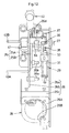
- FIG. 13 a front view showing the inner construction of the left operating device
- FIG. 20 an overall side view of the swiveling work vehicle.
- numeral 1 denotes a backhoe as an example of a work vehicle (swiveling work vehicle).
- This backhoe 1 includes an upper swiveling body (upper structure member) 2 , a traveling device 3 provided downwardly of the swiveling body 2 , a dozer device 5 as an implement attached to the front portion of the traveling device 3 , and an excavator device 7 as an implement attached to the front portion of the swiveling body 2 .
- a mounting portion 21 a for the driver's seat 8 In the upper face of the operating device 21 , there are formed a mounting portion 21 a for the driver's seat 8 , a mounting portion 21 b for the left operating device 21 and a mounting portion 21 c for the right operating device 23 and on these mounting portions 21 a - 21 c , the driver's seat 8 , the left operating device 22 and the right operating device 23 are mounted respectively and fixed thereto by means of fastening members such as bolts.
- the bottom face of a sheet 8 A has a right/left width greater than a cushioning member 8 B.
- the operating box 26 is provided in the form of a box by welding a right plate member 26 b forming the right wall and the rear wall to a left plate member 26 a forming the left wall, fixedly attaching an attaching plate 26 c to the front portions of these plate members, and fixedly attaching a bearing plate 26 d to the inner face of the right wall of the right plate member 26 a , and the left side face of the left plate member 26 a being substantially flush or adjacent, in the right/left direction, to the left leg portion 21 L of the operating deck 21 .
- the spacing between the left and right plate members 26 a , 26 b is shorter than the width of the attaching plate 26 c.
- the cam member 33 defines a cam groove 34 extending from the base end portion to the leading end of the member 33 , and from the support portion 2 B of the support bracket 25 , a guide pin 5 having a right/left axis projects and the cam groove 34 is engaged with this guide pin 35 via a cam follower.
- the pivot shaft 32 is positioned rearwardly and upwardly of the horizontal shaft 27 and the guide pin 35 is positioned forwardly and upwardly of the horizontal shaft 27 and at a position intermediate between the pivot shaft 32 and the horizontal shaft 27 .
- the cam member 33 extends forwardly and downwardly from the pivot shaft 32 and the cam groove 34 is formed with a length which allows a necessary angular, e.g. 50 degree fore/aft pivotal movement of the operating box 26 .
- a stay 37 is provided erect, and between this stay 37 and the attaching plate 26 c of the operating box 26 , a return spring 38 is incorporated to be contactable with a stopper 54 provided in the right plate member 26 a . And, by the return spring 38 , the unload lever 31 is urged in the depressing direction (the counterclockwise direction in FIGS. 9-11 ).
- the switch piece of the pivot detecting means 55 projects, thereby to detect pushing-up of the unload lever 31 (unloading condition), thus disabling operations of the swivel, arm, boom, bucket by the left and right operating devices 22 , 23 .
- a gas damper 39 for assisting the upward pivotal movement of the left operating device 22 , and there are provided also use position contacting means 41 and avoiding position contacting means 42 comprised of a cushion and a contacting portion.
- the tank room of the operational oil tank T or the like is disposed on the right side of the vehicle body 6 .
- the tank room can be disposed on the left side of the vehicle body 6 and the layouts of the operational tank T and the driver's seat 8 and the arrangements of the left and right operating devices 22 , 23 can be in reverse in the right and left direction.
Landscapes
- Engineering & Computer Science (AREA)
- Mining & Mineral Resources (AREA)
- Civil Engineering (AREA)
- General Engineering & Computer Science (AREA)
- Structural Engineering (AREA)
- Mechanical Engineering (AREA)
- Component Parts Of Construction Machinery (AREA)
- Operation Control Of Excavators (AREA)
Applications Claiming Priority (9)
| Application Number | Priority Date | Filing Date | Title |
|---|---|---|---|
| JP2008-084038 | 2008-03-27 | ||
| JP2008-084037 | 2008-03-27 | ||
| JP2008084036A JP4648962B2 (ja) | 2008-03-27 | 2008-03-27 | 作業機の操縦部構造 |
| JP2008084037A JP4746642B2 (ja) | 2008-03-27 | 2008-03-27 | 作業機の操縦部構造 |
| JP2008-084036 | 2008-03-27 | ||
| JPJP2008-084038 | 2008-03-27 | ||
| JPJP2008-084036 | 2008-03-27 | ||
| JPJP2008-084037 | 2008-03-27 | ||
| JP2008084038A JP4648963B2 (ja) | 2008-03-27 | 2008-03-27 | 作業機の操縦部構造 |
Publications (2)
| Publication Number | Publication Date |
|---|---|
| US20090243338A1 US20090243338A1 (en) | 2009-10-01 |
| US8038202B2 true US8038202B2 (en) | 2011-10-18 |
Family
ID=40809877
Family Applications (1)
| Application Number | Title | Priority Date | Filing Date |
|---|---|---|---|
| US12/411,096 Active 2030-01-21 US8038202B2 (en) | 2008-03-27 | 2009-03-25 | Operators section construction for work vehicle |
Country Status (4)
| Country | Link |
|---|---|
| US (1) | US8038202B2 (zh) |
| EP (1) | EP2105538B1 (zh) |
| KR (1) | KR101090637B1 (zh) |
| CN (1) | CN101545273B (zh) |
Cited By (4)
| Publication number | Priority date | Publication date | Assignee | Title |
|---|---|---|---|---|
| US20140017053A1 (en) * | 2011-06-13 | 2014-01-16 | Hitachi Construction Machinery Co., Ltd. | Construction machine |
| US20140367534A1 (en) * | 2013-06-13 | 2014-12-18 | Kobelco Construction Machinery Co., Ltd. | Sheet stand and working machine including same |
| US9707865B1 (en) * | 2016-05-04 | 2017-07-18 | Deere & Company | Operator seat swivel with arm release |
| US11274420B2 (en) * | 2019-07-02 | 2022-03-15 | Gugsoo An | Console box for excavator |
Families Citing this family (10)
| Publication number | Priority date | Publication date | Assignee | Title |
|---|---|---|---|---|
| JP5180248B2 (ja) * | 2010-03-09 | 2013-04-10 | 株式会社神戸製鋼所 | 油圧配管の支持構造及びこれを備えた作業機械 |
| KR101033666B1 (ko) * | 2010-10-11 | 2011-05-12 | 대호 (주) | 트랙터의 운전캡 |
| JP5881637B2 (ja) * | 2013-03-29 | 2016-03-09 | 株式会社クボタ | 作業機のキャビン装置 |
| CN103441441B (zh) * | 2013-08-30 | 2016-01-13 | 上海三一重机有限公司 | 一种插接抽拉式具有集成控制功能的座椅装置及机械设备 |
| CN106480923B (zh) * | 2015-09-02 | 2020-01-14 | 中国航空工业第六一八研究所 | 一种挖掘机高人机工效操纵装置 |
| US9745719B1 (en) * | 2016-02-29 | 2017-08-29 | Deere & Company | Mechanical control arrangement for work vehicle |
| US10837158B2 (en) * | 2018-02-07 | 2020-11-17 | Manitou Equipment America, Llc | Loader, operator seat assembly with integrated, non-electronic hydraulic pilot valves |
| CN109626218B (zh) * | 2019-01-03 | 2023-10-27 | 江龙船艇科技股份有限公司 | 一种船用室外同步旋转装吊装置 |
| CN112336105A (zh) * | 2019-08-09 | 2021-02-09 | 张寒 | 一种多维可调的工业设备控制联动台 |
| CN113998594B (zh) * | 2021-11-05 | 2024-05-14 | 江苏骁阳机械股份有限公司 | 一种吊机用具有散热效果的静音外壳总成 |
Citations (14)
| Publication number | Priority date | Publication date | Assignee | Title |
|---|---|---|---|---|
| JPH09195315A (ja) | 1996-01-22 | 1997-07-29 | Yutani Heavy Ind Ltd | 建設機械のフロアプレート構造 |
| US6039141A (en) * | 1998-02-23 | 2000-03-21 | Case Corporation | Moving operator and display unit |
| US6086142A (en) * | 1998-06-01 | 2000-07-11 | Caterpillar Inc. | Adjustable operator station for a work machine and an associated method for positioning an operator station relative to a cab floor of a work machine |
| JP2002149255A (ja) | 2000-11-10 | 2002-05-24 | Kubota Corp | 作業車の運転操縦装置 |
| US6612636B2 (en) * | 2001-08-29 | 2003-09-02 | Deere & Company | Hand reference for control panel of utility vehicle |
| JP2004116048A (ja) | 2002-09-24 | 2004-04-15 | Kubota Corp | 作業機 |
| US6942282B1 (en) * | 2004-06-17 | 2005-09-13 | Cnh America Llc | Wrap-around cab control layout for bale wagon |
| US20050210718A1 (en) | 2004-03-29 | 2005-09-29 | Kubota Corporation | Swiveling utility machine having swivel deck |
| US20060170251A1 (en) * | 2003-03-04 | 2006-08-03 | Hajime Ishii | Construction machine |
| US7243982B2 (en) * | 2004-06-22 | 2007-07-17 | Caterpillar Inc | Operator's cab for a work machine |
| JP2007217892A (ja) | 2006-02-14 | 2007-08-30 | Hitachi Constr Mach Co Ltd | 建設機械 |
| US20090195025A1 (en) * | 2008-01-31 | 2009-08-06 | James Shurts | Tether Attachment For Seat Tilting |
| US20100109380A1 (en) * | 2008-10-30 | 2010-05-06 | Caterpillar Forest Products Inc. | Wiper control arrangement |
| US20100187859A1 (en) * | 2009-01-27 | 2010-07-29 | Clark Equipment Company | Work Machine Vehicle Having Joystick Controls on an Adjustable Suspended Seatbar |
Family Cites Families (3)
| Publication number | Priority date | Publication date | Assignee | Title |
|---|---|---|---|---|
| DE9204392U1 (zh) * | 1992-04-01 | 1992-05-27 | Licentia Patent-Verwaltungs-Gmbh, 6000 Frankfurt, De | |
| JP4695017B2 (ja) * | 2006-05-12 | 2011-06-08 | 日立建機株式会社 | 建設機械 |
| CN201021500Y (zh) * | 2007-02-01 | 2008-02-13 | 徐州徐工特种工程机械有限公司 | 挖掘装载机驾驶室 |
-
2009
- 2009-03-12 KR KR1020090020968A patent/KR101090637B1/ko active IP Right Grant
- 2009-03-24 EP EP09156085.4A patent/EP2105538B1/en active Active
- 2009-03-25 US US12/411,096 patent/US8038202B2/en active Active
- 2009-03-27 CN CN2009101387025A patent/CN101545273B/zh active Active
Patent Citations (14)
| Publication number | Priority date | Publication date | Assignee | Title |
|---|---|---|---|---|
| JPH09195315A (ja) | 1996-01-22 | 1997-07-29 | Yutani Heavy Ind Ltd | 建設機械のフロアプレート構造 |
| US6039141A (en) * | 1998-02-23 | 2000-03-21 | Case Corporation | Moving operator and display unit |
| US6086142A (en) * | 1998-06-01 | 2000-07-11 | Caterpillar Inc. | Adjustable operator station for a work machine and an associated method for positioning an operator station relative to a cab floor of a work machine |
| JP2002149255A (ja) | 2000-11-10 | 2002-05-24 | Kubota Corp | 作業車の運転操縦装置 |
| US6612636B2 (en) * | 2001-08-29 | 2003-09-02 | Deere & Company | Hand reference for control panel of utility vehicle |
| JP2004116048A (ja) | 2002-09-24 | 2004-04-15 | Kubota Corp | 作業機 |
| US20060170251A1 (en) * | 2003-03-04 | 2006-08-03 | Hajime Ishii | Construction machine |
| US20050210718A1 (en) | 2004-03-29 | 2005-09-29 | Kubota Corporation | Swiveling utility machine having swivel deck |
| US6942282B1 (en) * | 2004-06-17 | 2005-09-13 | Cnh America Llc | Wrap-around cab control layout for bale wagon |
| US7243982B2 (en) * | 2004-06-22 | 2007-07-17 | Caterpillar Inc | Operator's cab for a work machine |
| JP2007217892A (ja) | 2006-02-14 | 2007-08-30 | Hitachi Constr Mach Co Ltd | 建設機械 |
| US20090195025A1 (en) * | 2008-01-31 | 2009-08-06 | James Shurts | Tether Attachment For Seat Tilting |
| US20100109380A1 (en) * | 2008-10-30 | 2010-05-06 | Caterpillar Forest Products Inc. | Wiper control arrangement |
| US20100187859A1 (en) * | 2009-01-27 | 2010-07-29 | Clark Equipment Company | Work Machine Vehicle Having Joystick Controls on an Adjustable Suspended Seatbar |
Cited By (5)
| Publication number | Priority date | Publication date | Assignee | Title |
|---|---|---|---|---|
| US20140017053A1 (en) * | 2011-06-13 | 2014-01-16 | Hitachi Construction Machinery Co., Ltd. | Construction machine |
| US20140367534A1 (en) * | 2013-06-13 | 2014-12-18 | Kobelco Construction Machinery Co., Ltd. | Sheet stand and working machine including same |
| US9382692B2 (en) * | 2013-06-13 | 2016-07-05 | Kobelco Construction Machinery Co., Ltd. | Seat stand and working machine including same |
| US9707865B1 (en) * | 2016-05-04 | 2017-07-18 | Deere & Company | Operator seat swivel with arm release |
| US11274420B2 (en) * | 2019-07-02 | 2022-03-15 | Gugsoo An | Console box for excavator |
Also Published As
| Publication number | Publication date |
|---|---|
| KR101090637B1 (ko) | 2011-12-08 |
| CN101545273A (zh) | 2009-09-30 |
| CN101545273B (zh) | 2012-02-15 |
| KR20090103722A (ko) | 2009-10-01 |
| US20090243338A1 (en) | 2009-10-01 |
| EP2105538A3 (en) | 2017-04-19 |
| EP2105538A2 (en) | 2009-09-30 |
| EP2105538B1 (en) | 2019-01-23 |
Similar Documents
| Publication | Publication Date | Title |
|---|---|---|
| US8038202B2 (en) | Operators section construction for work vehicle | |
| US8205701B2 (en) | Operating system for tractor | |
| US7530418B2 (en) | Construction machine | |
| JP4695017B2 (ja) | 建設機械 | |
| JP4988661B2 (ja) | 建設機械 | |
| KR100585924B1 (ko) | 건설 기계 | |
| JP4648963B2 (ja) | 作業機の操縦部構造 | |
| US9534354B2 (en) | Construction machine | |
| JP2007092278A (ja) | バックホーの上部構造 | |
| JP4746642B2 (ja) | 作業機の操縦部構造 | |
| JP4648962B2 (ja) | 作業機の操縦部構造 | |
| KR100938946B1 (ko) | 프론트 로더 및 이를 구비한 로더 작업기 | |
| JP4381364B2 (ja) | バックホー | |
| JP2007092327A (ja) | バックホー | |
| JP4703334B2 (ja) | バックホー | |
| JP4614894B2 (ja) | 作業車のキャノピ | |
| JP4515367B2 (ja) | バックホー | |
| JP4291219B2 (ja) | 建設機械 | |
| JP4738188B2 (ja) | 作業車のキャノピ | |
| JP2007092326A (ja) | バックホー | |
| JP2009023658A (ja) | トラクタ | |
| JP2000096611A (ja) | 旋回作業機 | |
| JPH0913423A (ja) | バックホー装置付きホイルローダ | |
| JP2005105603A (ja) | 旋回作業機 | |
| JP2002004319A (ja) | バックホウ |
Legal Events
| Date | Code | Title | Description |
|---|---|---|---|
| AS | Assignment |
Owner name: KUBOTA CORPORATION, JAPAN Free format text: ASSIGNMENT OF ASSIGNORS INTEREST;ASSIGNORS:UEDA, MASAAKI;SAKAI, TAKEHIRO;REEL/FRAME:022794/0939 Effective date: 20090423 |
|
| STCF | Information on status: patent grant |
Free format text: PATENTED CASE |
|
| FEPP | Fee payment procedure |
Free format text: PAYOR NUMBER ASSIGNED (ORIGINAL EVENT CODE: ASPN); ENTITY STATUS OF PATENT OWNER: LARGE ENTITY |
|
| FPAY | Fee payment |
Year of fee payment: 4 |
|
| MAFP | Maintenance fee payment |
Free format text: PAYMENT OF MAINTENANCE FEE, 8TH YEAR, LARGE ENTITY (ORIGINAL EVENT CODE: M1552); ENTITY STATUS OF PATENT OWNER: LARGE ENTITY Year of fee payment: 8 |
|
| MAFP | Maintenance fee payment |
Free format text: PAYMENT OF MAINTENANCE FEE, 12TH YEAR, LARGE ENTITY (ORIGINAL EVENT CODE: M1553); ENTITY STATUS OF PATENT OWNER: LARGE ENTITY Year of fee payment: 12 |