US7763377B2 - Electrochemical element having an ellipsoidal assembly configured for high power input - Google Patents
Electrochemical element having an ellipsoidal assembly configured for high power input Download PDFInfo
- Publication number
- US7763377B2 US7763377B2 US11/150,123 US15012305A US7763377B2 US 7763377 B2 US7763377 B2 US 7763377B2 US 15012305 A US15012305 A US 15012305A US 7763377 B2 US7763377 B2 US 7763377B2
- Authority
- US
- United States
- Prior art keywords
- positive
- negative
- electrode
- current collector
- lead
- Prior art date
- Legal status (The legal status is an assumption and is not a legal conclusion. Google has not performed a legal analysis and makes no representation as to the accuracy of the status listed.)
- Expired - Fee Related, expires
Links
- 239000003792 electrolyte Substances 0.000 claims abstract description 9
- 238000003466 welding Methods 0.000 claims description 21
- 239000007774 positive electrode material Substances 0.000 claims description 16
- 239000007773 negative electrode material Substances 0.000 claims description 14
- 238000004804 winding Methods 0.000 abstract description 8
- 239000011149 active material Substances 0.000 abstract description 3
- 230000000052 comparative effect Effects 0.000 description 15
- HBBGRARXTFLTSG-UHFFFAOYSA-N Lithium ion Chemical compound [Li+] HBBGRARXTFLTSG-UHFFFAOYSA-N 0.000 description 10
- 229910001416 lithium ion Inorganic materials 0.000 description 10
- 238000009413 insulation Methods 0.000 description 9
- 238000007789 sealing Methods 0.000 description 8
- 230000000712 assembly Effects 0.000 description 6
- 238000000429 assembly Methods 0.000 description 6
- 239000003990 capacitor Substances 0.000 description 5
- NUJOXMJBOLGQSY-UHFFFAOYSA-N manganese dioxide Chemical compound O=[Mn]=O NUJOXMJBOLGQSY-UHFFFAOYSA-N 0.000 description 4
- 229910052751 metal Inorganic materials 0.000 description 4
- 239000002184 metal Substances 0.000 description 4
- 238000012360 testing method Methods 0.000 description 4
- 238000001035 drying Methods 0.000 description 3
- 239000011888 foil Substances 0.000 description 3
- 238000002156 mixing Methods 0.000 description 3
- 239000000203 mixture Substances 0.000 description 3
- -1 polyethylene Polymers 0.000 description 3
- OIFBSDVPJOWBCH-UHFFFAOYSA-N Diethyl carbonate Chemical compound CCOC(=O)OCC OIFBSDVPJOWBCH-UHFFFAOYSA-N 0.000 description 2
- KMTRUDSVKNLOMY-UHFFFAOYSA-N Ethylene carbonate Chemical compound O=C1OCCO1 KMTRUDSVKNLOMY-UHFFFAOYSA-N 0.000 description 2
- SECXISVLQFMRJM-UHFFFAOYSA-N N-Methylpyrrolidone Chemical compound CN1CCCC1=O SECXISVLQFMRJM-UHFFFAOYSA-N 0.000 description 2
- 239000002033 PVDF binder Substances 0.000 description 2
- 239000011230 binding agent Substances 0.000 description 2
- 238000000748 compression moulding Methods 0.000 description 2
- 238000004898 kneading Methods 0.000 description 2
- 238000000034 method Methods 0.000 description 2
- 229920002981 polyvinylidene fluoride Polymers 0.000 description 2
- 238000003825 pressing Methods 0.000 description 2
- 229920003048 styrene butadiene rubber Polymers 0.000 description 2
- OKTJSMMVPCPJKN-UHFFFAOYSA-N Carbon Chemical compound [C] OKTJSMMVPCPJKN-UHFFFAOYSA-N 0.000 description 1
- RYGMFSIKBFXOCR-UHFFFAOYSA-N Copper Chemical compound [Cu] RYGMFSIKBFXOCR-UHFFFAOYSA-N 0.000 description 1
- 229910001290 LiPF6 Inorganic materials 0.000 description 1
- 229910002097 Lithium manganese(III,IV) oxide Inorganic materials 0.000 description 1
- 239000004698 Polyethylene Substances 0.000 description 1
- 239000006230 acetylene black Substances 0.000 description 1
- 230000003213 activating effect Effects 0.000 description 1
- 229910052782 aluminium Inorganic materials 0.000 description 1
- XAGFODPZIPBFFR-UHFFFAOYSA-N aluminium Chemical compound [Al] XAGFODPZIPBFFR-UHFFFAOYSA-N 0.000 description 1
- 229910021383 artificial graphite Inorganic materials 0.000 description 1
- 238000005452 bending Methods 0.000 description 1
- 239000011248 coating agent Substances 0.000 description 1
- 238000000576 coating method Methods 0.000 description 1
- 239000006258 conductive agent Substances 0.000 description 1
- 238000007796 conventional method Methods 0.000 description 1
- 239000011889 copper foil Substances 0.000 description 1
- 230000002950 deficient Effects 0.000 description 1
- 238000013461 design Methods 0.000 description 1
- 239000006185 dispersion Substances 0.000 description 1
- 230000004927 fusion Effects 0.000 description 1
- 238000005470 impregnation Methods 0.000 description 1
- 238000009434 installation Methods 0.000 description 1
- 239000012212 insulator Substances 0.000 description 1
- XGZVUEUWXADBQD-UHFFFAOYSA-L lithium carbonate Chemical compound [Li+].[Li+].[O-]C([O-])=O XGZVUEUWXADBQD-UHFFFAOYSA-L 0.000 description 1
- 239000011572 manganese Substances 0.000 description 1
- 238000004519 manufacturing process Methods 0.000 description 1
- 239000000463 material Substances 0.000 description 1
- 238000005259 measurement Methods 0.000 description 1
- 229910052987 metal hydride Inorganic materials 0.000 description 1
- 239000012046 mixed solvent Substances 0.000 description 1
- 238000012986 modification Methods 0.000 description 1
- 230000004048 modification Effects 0.000 description 1
- 229910052759 nickel Inorganic materials 0.000 description 1
- PXHVJJICTQNCMI-UHFFFAOYSA-N nickel Substances [Ni] PXHVJJICTQNCMI-UHFFFAOYSA-N 0.000 description 1
- 230000008520 organization Effects 0.000 description 1
- 229920000573 polyethylene Polymers 0.000 description 1
- 239000007787 solid Substances 0.000 description 1
- 239000002904 solvent Substances 0.000 description 1
Images




Classifications
-
- H—ELECTRICITY
- H01—ELECTRIC ELEMENTS
- H01M—PROCESSES OR MEANS, e.g. BATTERIES, FOR THE DIRECT CONVERSION OF CHEMICAL ENERGY INTO ELECTRICAL ENERGY
- H01M4/00—Electrodes
- H01M4/02—Electrodes composed of, or comprising, active material
- H01M4/13—Electrodes for accumulators with non-aqueous electrolyte, e.g. for lithium-accumulators; Processes of manufacture thereof
-
- H—ELECTRICITY
- H01—ELECTRIC ELEMENTS
- H01M—PROCESSES OR MEANS, e.g. BATTERIES, FOR THE DIRECT CONVERSION OF CHEMICAL ENERGY INTO ELECTRICAL ENERGY
- H01M10/00—Secondary cells; Manufacture thereof
- H01M10/04—Construction or manufacture in general
- H01M10/0431—Cells with wound or folded electrodes
-
- H—ELECTRICITY
- H01—ELECTRIC ELEMENTS
- H01M—PROCESSES OR MEANS, e.g. BATTERIES, FOR THE DIRECT CONVERSION OF CHEMICAL ENERGY INTO ELECTRICAL ENERGY
- H01M10/00—Secondary cells; Manufacture thereof
- H01M10/05—Accumulators with non-aqueous electrolyte
- H01M10/058—Construction or manufacture
- H01M10/0587—Construction or manufacture of accumulators having only wound construction elements, i.e. wound positive electrodes, wound negative electrodes and wound separators
-
- H—ELECTRICITY
- H01—ELECTRIC ELEMENTS
- H01M—PROCESSES OR MEANS, e.g. BATTERIES, FOR THE DIRECT CONVERSION OF CHEMICAL ENERGY INTO ELECTRICAL ENERGY
- H01M50/00—Constructional details or processes of manufacture of the non-active parts of electrochemical cells other than fuel cells, e.g. hybrid cells
- H01M50/50—Current conducting connections for cells or batteries
- H01M50/531—Electrode connections inside a battery casing
- H01M50/536—Electrode connections inside a battery casing characterised by the method of fixing the leads to the electrodes, e.g. by welding
-
- H—ELECTRICITY
- H01—ELECTRIC ELEMENTS
- H01M—PROCESSES OR MEANS, e.g. BATTERIES, FOR THE DIRECT CONVERSION OF CHEMICAL ENERGY INTO ELECTRICAL ENERGY
- H01M50/00—Constructional details or processes of manufacture of the non-active parts of electrochemical cells other than fuel cells, e.g. hybrid cells
- H01M50/50—Current conducting connections for cells or batteries
- H01M50/531—Electrode connections inside a battery casing
- H01M50/538—Connection of several leads or tabs of wound or folded electrode stacks
-
- H—ELECTRICITY
- H01—ELECTRIC ELEMENTS
- H01M—PROCESSES OR MEANS, e.g. BATTERIES, FOR THE DIRECT CONVERSION OF CHEMICAL ENERGY INTO ELECTRICAL ENERGY
- H01M10/00—Secondary cells; Manufacture thereof
- H01M10/05—Accumulators with non-aqueous electrolyte
- H01M10/052—Li-accumulators
- H01M10/0525—Rocking-chair batteries, i.e. batteries with lithium insertion or intercalation in both electrodes; Lithium-ion batteries
-
- Y—GENERAL TAGGING OF NEW TECHNOLOGICAL DEVELOPMENTS; GENERAL TAGGING OF CROSS-SECTIONAL TECHNOLOGIES SPANNING OVER SEVERAL SECTIONS OF THE IPC; TECHNICAL SUBJECTS COVERED BY FORMER USPC CROSS-REFERENCE ART COLLECTIONS [XRACs] AND DIGESTS
- Y02—TECHNOLOGIES OR APPLICATIONS FOR MITIGATION OR ADAPTATION AGAINST CLIMATE CHANGE
- Y02E—REDUCTION OF GREENHOUSE GAS [GHG] EMISSIONS, RELATED TO ENERGY GENERATION, TRANSMISSION OR DISTRIBUTION
- Y02E60/00—Enabling technologies; Technologies with a potential or indirect contribution to GHG emissions mitigation
- Y02E60/10—Energy storage using batteries
-
- Y—GENERAL TAGGING OF NEW TECHNOLOGICAL DEVELOPMENTS; GENERAL TAGGING OF CROSS-SECTIONAL TECHNOLOGIES SPANNING OVER SEVERAL SECTIONS OF THE IPC; TECHNICAL SUBJECTS COVERED BY FORMER USPC CROSS-REFERENCE ART COLLECTIONS [XRACs] AND DIGESTS
- Y02—TECHNOLOGIES OR APPLICATIONS FOR MITIGATION OR ADAPTATION AGAINST CLIMATE CHANGE
- Y02P—CLIMATE CHANGE MITIGATION TECHNOLOGIES IN THE PRODUCTION OR PROCESSING OF GOODS
- Y02P70/00—Climate change mitigation technologies in the production process for final industrial or consumer products
- Y02P70/50—Manufacturing or production processes characterised by the final manufactured product
Definitions
- the present invention relates to an electrochemical element such as a battery or an electric double layer capacitor having a prismatic outer shape and comprising an electrode assembly composed of positive and negative electrodes wound into a flat shape, and being accommodated into a case together with an electrolyte.
- the invention relates to an electrochemical element having a current collection structure designed for high power output.
- an electrode assembly having a winding structure composed of positive and negative electrodes wound with a separator interposed therebetween is widely employed in order to increase a reaction area per unit volume.
- the electrode assembly is accommodated in a metal case with an electrolyte, and the case is sealed.
- An electrochemical element is configured through connecting the positive and negative electrodes to portions serving as positive and external negative connection terminals, respectively, for allowing an external connection.
- the positive and negative electrodes are formed by coating an active material to a current collector made of a foil or a thin metal mesh plate, and thus a current path is created through connecting the positive and negative current collectors to portions serving as positive and external negative connection terminals, respectively, by leads.
- a current path from a distant portion in the wound strip-shaped current collector to the connected portion becomes longer, resulting in an increase in electrical loss and temperature rise during a high-rate charge/discharge.
- the internal resistance of a current path should be reduced as much as possible.
- an electrode assembly is formed into a cylindrical shape through winding positive and negative electrodes with a separator interposed therebetween such that part of a current collector of the positive or negative electrode is protruded from one end of the electrode assembly.
- the current collector protruded from the end is bent inward by pressing the protruded collector in a direction of cylinder axis to form flat regions, and a current collecting plate is welded to the flat regions.
- strip-shaped positive and negative electrodes each having a current collector exposed from an edge in the width direction of the strip are wound around a flat winding core to which metal plates serving as positive and negative terminals are attached.
- the positive and negative terminals are welded to the exposed current collector portions of the positive and negative electrodes, respectively, to form a flat wound electrode, and the end of the each of the positive and negative terminals is extended from a battery case.
- an electrode assembly is formed such that a plurality of current collecting leads are projected from the current collectors of the wound positive and negative electrodes along a line in a radial direction.
- the plurality of current collecting leads arranged in the radial direction are bundled, and the bundled portion is clamped with a terminal member made of the same material as the current collecting lead. The clamped portion is then welded to form an output terminal.
- the present invention has been made in view of the above problems in the conventional techniques. It is an object of the present invention to provide an electrochemical element comprising a connection structure which improves the current collection efficiency from an electrode assembly.
- an electrochemical element comprising an electrode assembly accommodated in a case with an electrolyte, the electrode assembly including a positive electrode formed of a strip-shaped positive current collector coated with a positive electrode active material and a negative electrode formed of a strip-shaped negative current collector coated with a negative electrode active material, the positive electrode and the negative electrode being wound around with a separator interposed therebetween, a positive lead bonded to the positive electrode being connected to a portion serving as an external positive connection terminal, and a negative lead bonded to the negative electrode being connected to a portion serving as an external negative connection terminal.
- the positive electrode includes an exposed current collector portion at least at one end in a width direction where the positive electrode active material has not been coated.
- the negative electrode includes an exposed current collector portion at least at the other end in the width direction where the negative electrode active material has not been coated.
- the separator has a smaller width than those of the positive and negative electrodes, and the positive and negative electrodes with the separator interposed therebetween are wound around to form the electrode assembly having an ellipsoidal cross-section.
- the exposed current collector portion of the positive electrode protruding beyond the separator from the one end is pressed in the shorter side direction of the ellipsoidal cross-section and is welded to form a welding joint
- the exposed current collector portion of the negative electrode protruding beyond the separator from the other end is pressed in the shorter side direction of the ellipsoidal cross-section and is welded to form a welding joint.
- the strip-shaped positive and negative electrodes are wound around into a flat shape to form the electrode assembly. Subsequently, the exposed current collector portion of the positive electrode protruding beyond the separator from the one end of the electrode assembly is pressed to be brought into contact with each other and welded, and the exposed current collector portion of the negative electrode protruding beyond the separator from the other end of the electrode assembly is pressed to be brought into contact with each other and welded. Therefore, the positive electrode is connected to the positive lead at a plurality of portions, and also the negative electrode is connected to the negative lead at a plurality of portions.
- an electrochemical element comprising an electrode assembly accommodated in a case with an electrolyte, the electrode assembly including a positive electrode formed of a strip-shaped positive current collector coated with a positive electrode active material and a negative electrode formed of a strip-shaped negative current collector coated with a negative electrode active material, the positive electrode and the negative electrode being wound around with a separator interposed therebetween, a positive lead bonded to the positive electrode being connected to a portion serving as an external positive connection terminal, and a negative lead bonded to the negative electrode being connected to a portion serving as an external negative connection terminal.
- the positive or negative electrode includes an exposed current collector portion at least at one end in a width direction where the positive or negative electrode active material has not been coated.
- the separator has a smaller width than those of the positive and negative electrodes, and the positive and negative electrodes with the separator interposed therebetween are wound around to form the electrode assembly having an ellipsoidal cross-section.
- the exposed current collector portion of the positive or negative electrode protruding beyond the separator from the one end is pressed in the shorter side direction of the ellipsoidal cross-section and is welded to form a welding joint.
- the positive and negative electrodes are wound around into a flat shape to form the electrode assembly. Subsequently, the exposed current collector portion of the positive or negative electrode is pressed and welded at the one end side. Then, the positive or negative electrode is connected to the lead at a plurality of portions. Therefore, an electrochemical element having a small internal resistance and excellent current collection efficiency is configured.
- the position of the separator interposed between the positive and negative electrodes and the width of the separator are adjusted such that the edges thereof are located inside the edge of the exposed current collector portion to be pressed and welded and are located outside the edge of the electrode not to be pressed and welded. Therefore, a short-circuited between the positive and negative electrodes due to the deformation of the electrodes is prevented during pressing the exposed current collector portion.
- connection of the positive and negative leads to the positive and negative electrodes may be configured such that the positive lead is connected to the exposed current collector portion formed on the positive electrode in one end in the lengthwise direction and the negative lead is connected to the exposed current collector portion formed on the negative electrode in the other end in the lengthwise direction.
- the positive or negative lead may also be connected to the exposed current collector portion to be pressed and welded. In this case, the configuration of the positive and negative electrodes may be simplified.
- FIG. 1 is a cross-sectional view showing the configuration of a lithium ion rechargeable battery according to one embodiment of the present invention
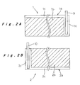
- FIG. 2A is a plan view showing the configuration of a positive electrode of the battery shown in FIG. 1
- FIG. 2B is a plan view showing the configuration of a negative electrode of the battery shown in FIG. 1 ;
- FIGS. 3A and 3B are schematic cross-sectional views showing the configuration of the electrode assembly employing the electrodes of the above;
- FIG. 4 is a perspective view showing the configuration of the electrode assembly
- FIG. 5 is a schematic illustration showing the electrode structure of the prior art applied to a Comparative Example.
- FIG. 6 is a schematic illustration showing the electrode structure of the prior art applied to another Comparative Example.
- the connection structure according to the present invention is applied to a lithium ion rechargeable battery which is an example of an electrochemical element.
- the lithium ion rechargeable battery according to the present embodiment has an outer shape of a flat prismatic shape, and comprises an electrode assembly 4 accommodated in a battery case 12 .
- the electrode assembly 4 is formed by winding a positive electrode and a negative electrode with a separator interposed therebetween such that the cross section thereof has an ellipsoidal shape.
- a positive lead 9 pulled out from the positive electrode is electrically connected to an external positive connection terminal 21 provided in a sealing plate 14 which seals the opening of the battery case 12 and is insulated from the external positive connection terminal 21 .
- a negative lead 10 is pulled out from the negative electrode and is connected to the sealing plate 14 .
- the positive electrode 1 composing the electrode assembly 4 is formed from a strip-shaped positive current collector 1 a having a required length and a width. Both sides of the positive current collector 1 a are coated with a positive electrode active material 1 b such that an uncoated exposed positive current collector portion 1 c is formed on each side at one end in the width direction and one end in the lengthwise direction. A positive lead 9 is welded on the exposed positive current collector portion 1 c formed in the one end in the lengthwise direction on the positive current collector 1 a .
- a solution of polyvinylidene fluoride in a solvent N-methylpyrrolidone (NMP)
- NMP N-methylpyrrolidone
- the paste of the positive electrode active material 1 b is applied to both sides of the positive electrode collector 1 a made of aluminum foil having a thickness of 15 ⁇ m such that the uncoated exposed positive current collector portion 1 c having a predetermined width is formed at the one end in the width direction and the one end in the lengthwise direction, and the coated positive electrode active material is subjected to drying.
- the layers of the positive electrode active material 1 b are formed such that the total thickness of the coated positive electrode active material on both the sides after drying is 280 ⁇ m, which is reduced to 200 ⁇ m by compression molding.
- the negative electrode 2 is formed from a strip-shaped negative current collector 2 a having a required length and a width. Both sides of the negative current collector 2 a are coated with a negative electrode active material 2 b such that an uncoated exposed negative current collector portion 2 c is formed on each side at the other end (opposite to the one end) in the width direction and the other end (opposite to the one end) in the lengthwise direction. A negative lead 10 is welded on the exposed negative current collector portion 2 c formed in the other end in the lengthwise direction on the negative current collector 2 a .
- the negative electrode active material 2 b is prepared through mixing artificial graphite with styrene-butadiene rubber (SBR) serving as a binder in a ratio by weight of 97:3.
- SBR styrene-butadiene rubber
- an aqueous dispersion of styrene-butadiene rubber is employed, and the above mixing ratio is based on the solid contents.
- the paste of the negative electrode active material 2 b is applied to both sides of the negative electrode collector 2 a made of a copper foil having a thickness of 14 ⁇ m such that the uncoated exposed negative current collector portion 2 c having a predetermined width is formed at the other end in the width direction and the other end in the lengthwise direction, and the coated negative electrode is subjected to drying.
- the coated negative electrode 2 is subjected to compression molding to obtain a thickness of 170 ⁇ m.
- the positive and negative electrodes 1 and 2 configured as above are layered with a separator 3 made of a microporous polyethylene film interposed therebetween, and wound around into a spiral shape to form the electrode assembly 4 having an ellipsoidal cross-section.
- the layered positions of the positive and negative electrodes 1 and 2 and the width of the separator 3 are adjusted such that, at the one end side in which the exposed positive current collector portion 1 c is formed on the positive electrode 1 in the width direction, the exposed positive current collector portion 1 c is located outside the one edge of the separator 3 and the one edge of the negative electrode 2 is located inside the one edge of the separator 3 .
- the exposed negative current collector portion 2 c is located outside the other edge of the separator 3 and the other edge of the positive electrode 1 is located inside the other edge of the separator 3 , as shown in FIG. 3A .
- the layered portions of the exposed positive current collector portion 1 c of the positive electrode 1 are pressed in the thickness direction of the wound electrode assembly 4 and brought the layered portions of the exposed positive current collector portion 1 c adjacent to each other through the negative electrode 2 and the separator 3 into pressure contact.
- the pressure-contacted portion is then welded at a welding point S to form a welding joint, as shown in FIGS. 3B and 4 .
- the layered portions of the exposed negative current collector portion 2 c of the negative electrode 2 are pressed in the thickness direction of the wound electrode assembly 4 and brought the layered portions of the exposed negative current collector portion 2 c adjacent to each other through the positive electrode plate 1 and the separator 3 into pressure contact.
- the pressure-contacted portion is then welded at a welding portion S to form a welding joint. Only one welding portion S may be employed, but the welding joint is preferably made at a plurality of welding portions.
- the electrode assembly 4 configured as above is then inserted into the battery case 12 formed into a flat prismatic tube having a bottom as shown in FIG. 1 .
- One end of the positive lead 9 is bonded to the exposed positive current collector portion 1 c formed in the lengthwise direction on the positive electrode 1 composing the electrode assembly 4 , and the other end of the positive lead 9 is welded to the external positive connection terminal 21 insulatingly attached to the sealing plate 14 through the use of an insulator 15 .
- one end of the negative lead 10 is bonded to the exposed negative current collector portion 2 c formed in the lengthwise direction on the negative electrode 2 , and the other end of the negative lead 10 is welded to the sealing plate 14 .
- the periphery of the sealing plate 14 to which the positive and negative leads 9 and 10 are bonded, is laser-welded to the opening of the battery case 12 to seal the opening of the battery case 12 .
- An inlet 18 is provided in the sealing plate 14 , and an electrolyte is introduced into the battery case 12 though the inlet 18 .
- a sealing plug 19 is welded to the inlet 18 for hermetically sealing the battery case 12 , and thus the assembly of the lithium ion rechargeable battery having a flat prismatic shape is completed.
- the electrolyte employed is a mixed solvent of ethylene carbonate (EC) and diethyl carbonate (DEC) at volume ratio of 1:1 with a 1 mol/dm 3 lithium hexafluorophosphate (LiPF 6 ) dissolved therein.
- EC ethylene carbonate
- DEC diethyl carbonate
- the lithium ion rechargeable battery configured as above has a prismatic outer shape, and comprises a current collecting structure which supports a high-rate charge/discharge current. Therefore, a battery pack with space efficiency will be configured by combining such a plurality of the lithium ion rechargeable batteries, and such battery pack is preferable to be employed as a power source of an electric tool or electric vehicle.
- prismatic lithium ion rechargeable batteries (width: 50 mm, height: 95 mm, thickness: 10 mm, design capacity: 3000 mAh) were fabricated by use of the structure of the embodiment and conventional structure for comparison.
- Example 1 the current collecting structure according to the above embodiment is applied, and in Example 2, the current collecting structure according to the embodiment is applied only to the negative electrode side configuration.
- Comparative Example 1 a conventional structure is applied. In this case, positive and negative electrodes each having an exposed current collector portion formed in one end in the width direction of each electrode are wound around into a flat shape, and respective current collector plates are welded to the exposed current collector portion extending from one end of the positive electrode and the exposed current collector portion extending from the other end of the negative electrode, as shown in FIG. 5 .
- Comparative Example 2 a conventional structure is also applied.
- a positive or negative lead is welded to an exposed current collector portion formed in one end in the lengthwise direction of either the corresponding positive or negative electrode, and the positive and negative electrodes are wound around into a flat shape.
- the electrode assemblies having the abovementioned structures were fabricated, and a direct current resistance was measured by means of an insulation resistance tester connected to the positive and negative leads. An electrode assembly having a direct current resistance of less than 1 M ⁇ was determined as a defective, and the results shown in Table 1 were obtained. In Examples 1 and 2 and Comparative Example 2, insulation failure was not detected. However, 20 electrode assemblies of Comparative Example 1 out of 100 assemblies had insulation failure which might be generated during the welding process. In the electrode assemblies having insulation failure, a hole generated due to the heat during welding was found to be observed in the separator around the positive current collecting terminal, and the negative and positive electrodes were brought into contact. In this regard, it is concluded that the connection structure in which the periphery of the electrode is welded cannot not be properly applied to a device such as a lithium ion battery employing a thin electrode current collector.
- Batteries were fabricated using the electrode assemblies which had passed the insulation fault test.
- the batteries were charged at a constant current of 1500 mA up to 4.2V, and discharged at a constant current of 1500 mA to 3.0V. This cycle was repeated three times in total for activating the batteries. Subsequently, the internal resistance was measured by use of an AC current having a measuring frequency of 1 kHz. The results are shown in Table 2.
- the batteries of Examples 1 and 2 and Comparative Example 1 have a small internal resistance (about 4.5 to 9.0 m ⁇ , on average).
- the batteries of Comparative Example 2 have a large internal resistance (about 15.5 m ⁇ , on average). This is because the electron conduction from the electrode at the opposite end to the current collector lead is inefficient in the batteries of Comparative Example 2.
- the distance to the current collector lead is shortened in the connection structure of the other batteries, resulting in the reduction in the internal resistance.
- the current collecting structure of the present invention has been applied to a lithium ion rechargeable battery.
- the present invention may also be applied to a battery having other wound electrode assembly structure such as a nickel metal hydride battery and an electric double layer capacitor.
- an electrochemical element having a small internal resistance and a high power output is produced with a high yield by means of the current collection structure according to the present invention. Therefore, an electrochemical element preferable for a driving power source of a power tool or an electric vehicle in which a charge/discharge at a high-rate current is required is provided.
Landscapes
- Chemical & Material Sciences (AREA)
- Chemical Kinetics & Catalysis (AREA)
- Electrochemistry (AREA)
- General Chemical & Material Sciences (AREA)
- Engineering & Computer Science (AREA)
- Manufacturing & Machinery (AREA)
- Materials Engineering (AREA)
- Connection Of Batteries Or Terminals (AREA)
- Secondary Cells (AREA)
- Battery Electrode And Active Subsutance (AREA)
- Electric Double-Layer Capacitors Or The Like (AREA)
Applications Claiming Priority (2)
| Application Number | Priority Date | Filing Date | Title |
|---|---|---|---|
| JP2004175186A JP5032737B2 (ja) | 2004-06-14 | 2004-06-14 | 電気化学素子 |
| JP2004-175186 | 2004-06-14 |
Publications (2)
| Publication Number | Publication Date |
|---|---|
| US20050277022A1 US20050277022A1 (en) | 2005-12-15 |
| US7763377B2 true US7763377B2 (en) | 2010-07-27 |
Family
ID=35460923
Family Applications (1)
| Application Number | Title | Priority Date | Filing Date |
|---|---|---|---|
| US11/150,123 Expired - Fee Related US7763377B2 (en) | 2004-06-14 | 2005-06-13 | Electrochemical element having an ellipsoidal assembly configured for high power input |
Country Status (3)
| Country | Link |
|---|---|
| US (1) | US7763377B2 (ja) |
| JP (1) | JP5032737B2 (ja) |
| CN (2) | CN101916840B (ja) |
Cited By (9)
| Publication number | Priority date | Publication date | Assignee | Title |
|---|---|---|---|---|
| US20100173194A1 (en) * | 2007-07-20 | 2010-07-08 | Naoko Fujiya | Electric energy storage device and manufactruing method thereof |
| US20100287763A1 (en) * | 2008-01-22 | 2010-11-18 | Kenji Tsuchiya | Battery production method |
| CN102856519A (zh) * | 2011-07-01 | 2013-01-02 | 株式会社杰士汤浅国际 | 蓄电元件及衬垫 |
| US9030805B2 (en) | 2012-03-28 | 2015-05-12 | Panasonic Intellectual Property Management Co., Ltd. | Capacitor and capacitor module using the same |
| US9281511B2 (en) | 2010-04-19 | 2016-03-08 | Gs Yuasa International Ltd. | Battery cell and device provided with the battery cell |
| US20190237811A1 (en) * | 2017-03-28 | 2019-08-01 | Lg Chem, Ltd. | Pouch-Shaped Secondary Battery Having Structure In Which Bidirectional Cell Is Changed To Unidirectional Cell |
| US11335980B2 (en) * | 2017-03-17 | 2022-05-17 | Libest Inc. | Flexible battery |
| US11380965B2 (en) * | 2015-05-06 | 2022-07-05 | Samsung Electronics Co., Ltd | Cell structure for secondary battery and secondary battery having the cell structure |
| WO2025149138A1 (de) * | 2024-01-11 | 2025-07-17 | Bayerische Motoren Werke Aktiengesellschaft | Baugruppe, elektrische zelle und verfahren zur herstellung einer baugruppe für eine elektrische zelle |
Families Citing this family (32)
| Publication number | Priority date | Publication date | Assignee | Title |
|---|---|---|---|---|
| US20110016706A1 (en) * | 2006-04-19 | 2011-01-27 | Exa Energy Technology Co., Ltd. | Rechargeable battery fabrication method |
| US7706129B2 (en) * | 2006-05-29 | 2010-04-27 | Panasonic Corporation | Electric double-layer capacitor and method for manufacturing the same |
| US20080026293A1 (en) * | 2006-07-26 | 2008-01-31 | Eveready Battery Company, Inc. | Lithium-iron disulfide cylindrical cell with modified positive electrode |
| CN101174681B (zh) | 2006-10-30 | 2010-05-12 | 比亚迪股份有限公司 | 极片复合体、电芯和锂离子电池 |
| JP4501081B2 (ja) * | 2006-12-06 | 2010-07-14 | ソニー株式会社 | 電極の形成方法および電池の製造方法 |
| CN101453002A (zh) | 2007-11-29 | 2009-06-10 | 比亚迪股份有限公司 | 一种电池及其制备方法 |
| CN201146200Y (zh) | 2007-12-18 | 2008-11-05 | 比亚迪股份有限公司 | 一种电池组用壳体及包括该壳体的电池组 |
| JP5132783B2 (ja) * | 2007-12-25 | 2013-01-30 | ビーワイディー カンパニー リミテッド | 加熱端子を有するバッテリシステム |
| US8092936B2 (en) | 2007-12-25 | 2012-01-10 | Byd Co. Ltd. | Electrochemical cell having a coiled core |
| US20090159354A1 (en) | 2007-12-25 | 2009-06-25 | Wenfeng Jiang | Battery system having interconnected battery packs each having multiple electrochemical storage cells |
| US8420254B2 (en) | 2007-12-25 | 2013-04-16 | Byd Co. Ltd. | End cover assembly for an electrochemical cell |
| US8276695B2 (en) | 2007-12-25 | 2012-10-02 | Byd Co. Ltd. | Battery electrode sheet |
| JP4359857B1 (ja) * | 2008-05-13 | 2009-11-11 | トヨタ自動車株式会社 | 角型電池 |
| JP5420888B2 (ja) * | 2008-12-15 | 2014-02-19 | パナソニック株式会社 | 電池 |
| JP5299980B2 (ja) * | 2008-12-19 | 2013-09-25 | エルジー ケム. エルティーディ. | 高出力リチウム二次電池 |
| JP5327523B2 (ja) * | 2009-02-10 | 2013-10-30 | トヨタ自動車株式会社 | 二次電池 |
| US20110052969A1 (en) * | 2009-09-01 | 2011-03-03 | Gm Global Technology Operations, Inc. | Cell tab joining for battery modules |
| KR101156331B1 (ko) * | 2010-01-26 | 2012-06-13 | 에스비리모티브 주식회사 | 전극 조립체, 상기 전극 조립체를 제조하는 방법 및 상기 전극 조립체를 포함하는 이차전지 |
| US9048487B2 (en) | 2010-09-13 | 2015-06-02 | Samsung Sdi Co., Ltd. | Secondary battery and manufacturing method thereof |
| JP6066254B2 (ja) * | 2011-09-27 | 2017-01-25 | 株式会社Gsユアサ | 蓄電素子、及び蓄電素子の製造方法 |
| KR20130049535A (ko) * | 2011-11-04 | 2013-05-14 | 삼성에스디아이 주식회사 | 이차 전지 |
| WO2015151580A1 (ja) | 2014-03-31 | 2015-10-08 | Necエナジーデバイス株式会社 | 二次電池 |
| JP6735445B2 (ja) | 2014-06-26 | 2020-08-05 | パナソニックIpマネジメント株式会社 | 捲回型電池 |
| CN104851596A (zh) * | 2015-05-26 | 2015-08-19 | 铜陵同飞科技有限公司 | 一种超级电容器电极芯及超级电容器制作方法 |
| JP6935798B2 (ja) * | 2016-07-29 | 2021-09-15 | 三洋電機株式会社 | 二次電池の製造方法 |
| KR102624595B1 (ko) * | 2016-12-23 | 2024-01-15 | 삼성전자주식회사 | 배터리의 활물질 도포 방법 및 상기 배터리를 구비한 전자 장치 |
| CN108400276B (zh) * | 2017-02-06 | 2021-03-05 | 丰田自动车株式会社 | 二次电池及其制造方法 |
| DE202018006912U1 (de) | 2017-04-14 | 2024-05-16 | Lg Energy Solution, Ltd. | Sekundärbatterie und Herstellung |
| CN112447937B (zh) * | 2019-09-04 | 2024-07-09 | 通用汽车环球科技运作有限责任公司 | 具有高长宽比电极的电化学电芯 |
| KR20210037929A (ko) * | 2019-09-30 | 2021-04-07 | 현대자동차주식회사 | 전기자동차용 배터리 셀 및 이의 제조방법 |
| KR102856167B1 (ko) * | 2020-06-08 | 2025-09-04 | 주식회사 엘지에너지솔루션 | 전극 조립체 및 이를 포함하는 이차 전지 |
| KR102794895B1 (ko) * | 2022-01-19 | 2025-04-14 | 삼성에스디아이 주식회사 | 이차 전지 |
Citations (10)
| Publication number | Priority date | Publication date | Assignee | Title |
|---|---|---|---|---|
| US5154993A (en) * | 1990-04-27 | 1992-10-13 | Eveready Battery Company, Inc. | Electrode strips for coiled assemblies and method of producing them |
| JPH09180761A (ja) | 1995-12-27 | 1997-07-11 | Fuji Elelctrochem Co Ltd | スパイラル形リチウムイオン二次電池 |
| JPH1050556A (ja) | 1996-08-05 | 1998-02-20 | Okamura Kenkyusho:Kk | 電気二重層コンデンサ |
| JP2000040501A (ja) | 1998-07-21 | 2000-02-08 | Denso Corp | 扁平巻回電極電池 |
| JP2000294222A (ja) | 1999-04-08 | 2000-10-20 | Matsushita Electric Ind Co Ltd | 二次電池 |
| JP2001038475A (ja) * | 1999-07-29 | 2001-02-13 | Denso Corp | 積層体の接合方法および電池 |
| CN2598160Y (zh) | 2002-12-30 | 2004-01-07 | 比亚迪股份有限公司 | 方型锂离子二次电池 |
| US20040061476A1 (en) | 2002-09-18 | 2004-04-01 | Matsushita Electric Industrial Co., Ltd. | Prismatic battery |
| US20050058908A1 (en) | 2003-09-17 | 2005-03-17 | Sanyo Electric Co., Ltd. | Secondary cell |
| US20050214642A1 (en) | 2004-03-29 | 2005-09-29 | Kim Ki-Ho | Electrode package and secondary battery using the same |
Family Cites Families (4)
| Publication number | Priority date | Publication date | Assignee | Title |
|---|---|---|---|---|
| JPH1154111A (ja) * | 1997-08-05 | 1999-02-26 | Japan Storage Battery Co Ltd | 二次電池用電極シート及び二次電池 |
| JP2000150306A (ja) * | 1998-11-12 | 2000-05-30 | Toyota Motor Corp | 電池またはキャパシタの集電方式 |
| JP3551365B2 (ja) * | 2000-06-20 | 2004-08-04 | 株式会社デンソー | 扁平形状巻回型電極電池 |
| JP4061938B2 (ja) * | 2001-12-20 | 2008-03-19 | トヨタ自動車株式会社 | 蓄電素子およびその製造方法 |
-
2004
- 2004-06-14 JP JP2004175186A patent/JP5032737B2/ja not_active Expired - Fee Related
-
2005
- 2005-06-13 US US11/150,123 patent/US7763377B2/en not_active Expired - Fee Related
- 2005-06-14 CN CN2010102667153A patent/CN101916840B/zh not_active Expired - Fee Related
- 2005-06-14 CN CNA2005100763348A patent/CN1716658A/zh active Pending
Patent Citations (12)
| Publication number | Priority date | Publication date | Assignee | Title |
|---|---|---|---|---|
| US5154993A (en) * | 1990-04-27 | 1992-10-13 | Eveready Battery Company, Inc. | Electrode strips for coiled assemblies and method of producing them |
| JPH09180761A (ja) | 1995-12-27 | 1997-07-11 | Fuji Elelctrochem Co Ltd | スパイラル形リチウムイオン二次電池 |
| JPH1050556A (ja) | 1996-08-05 | 1998-02-20 | Okamura Kenkyusho:Kk | 電気二重層コンデンサ |
| JP2000040501A (ja) | 1998-07-21 | 2000-02-08 | Denso Corp | 扁平巻回電極電池 |
| JP2000294222A (ja) | 1999-04-08 | 2000-10-20 | Matsushita Electric Ind Co Ltd | 二次電池 |
| JP2001038475A (ja) * | 1999-07-29 | 2001-02-13 | Denso Corp | 積層体の接合方法および電池 |
| US20040061476A1 (en) | 2002-09-18 | 2004-04-01 | Matsushita Electric Industrial Co., Ltd. | Prismatic battery |
| CN2598160Y (zh) | 2002-12-30 | 2004-01-07 | 比亚迪股份有限公司 | 方型锂离子二次电池 |
| US20050058908A1 (en) | 2003-09-17 | 2005-03-17 | Sanyo Electric Co., Ltd. | Secondary cell |
| CN1599117A (zh) | 2003-09-17 | 2005-03-23 | 三洋电机株式会社 | 二次电池 |
| US20050214642A1 (en) | 2004-03-29 | 2005-09-29 | Kim Ki-Ho | Electrode package and secondary battery using the same |
| CN1681146A (zh) | 2004-03-29 | 2005-10-12 | 三星Sdi株式会社 | 电极封装及使用该电极封装的二次电池 |
Non-Patent Citations (7)
| Title |
|---|
| English language Abstract of CN 1599117, Mar. 23, 2005. |
| English language Abstract of CN 1681146, Oct. 12, 2005. |
| English Language Abstract of JP 10-050556, Feb. 20, 1998. |
| English Language Abstract of JP 2000-040501, Feb. 8, 2000. |
| English Language Abstract of JP 2000-294222, Oct. 20, 2000. |
| English language Abstract of JP 9-180761, Jul. 11, 1997. |
| U.S. Appl. No. 11/150,095 to Kozuki et al., filed Jun. 13, 2005. |
Cited By (14)
| Publication number | Priority date | Publication date | Assignee | Title |
|---|---|---|---|---|
| US20100173194A1 (en) * | 2007-07-20 | 2010-07-08 | Naoko Fujiya | Electric energy storage device and manufactruing method thereof |
| US8283067B2 (en) * | 2007-07-20 | 2012-10-09 | Enax, Inc. | Electric energy storage device and manufacturing method thereof |
| US20100287763A1 (en) * | 2008-01-22 | 2010-11-18 | Kenji Tsuchiya | Battery production method |
| US8734537B2 (en) * | 2008-01-22 | 2014-05-27 | Toyota Jidosha Kabushiki Kaisha | Battery production method |
| US9281511B2 (en) | 2010-04-19 | 2016-03-08 | Gs Yuasa International Ltd. | Battery cell and device provided with the battery cell |
| CN102856519B (zh) * | 2011-07-01 | 2016-01-20 | 株式会社杰士汤浅国际 | 蓄电元件及衬垫 |
| CN102856519A (zh) * | 2011-07-01 | 2013-01-02 | 株式会社杰士汤浅国际 | 蓄电元件及衬垫 |
| US9030805B2 (en) | 2012-03-28 | 2015-05-12 | Panasonic Intellectual Property Management Co., Ltd. | Capacitor and capacitor module using the same |
| US11380965B2 (en) * | 2015-05-06 | 2022-07-05 | Samsung Electronics Co., Ltd | Cell structure for secondary battery and secondary battery having the cell structure |
| US11335980B2 (en) * | 2017-03-17 | 2022-05-17 | Libest Inc. | Flexible battery |
| US12068506B2 (en) | 2017-03-17 | 2024-08-20 | Libest Inc. | Flexible battery |
| US20190237811A1 (en) * | 2017-03-28 | 2019-08-01 | Lg Chem, Ltd. | Pouch-Shaped Secondary Battery Having Structure In Which Bidirectional Cell Is Changed To Unidirectional Cell |
| US11114700B2 (en) * | 2017-03-28 | 2021-09-07 | Lg Chem, Ltd. | Pouch-shaped secondary battery having structure in which bidirectional cell is changed to unidirectional cell |
| WO2025149138A1 (de) * | 2024-01-11 | 2025-07-17 | Bayerische Motoren Werke Aktiengesellschaft | Baugruppe, elektrische zelle und verfahren zur herstellung einer baugruppe für eine elektrische zelle |
Also Published As
| Publication number | Publication date |
|---|---|
| JP5032737B2 (ja) | 2012-09-26 |
| CN101916840A (zh) | 2010-12-15 |
| CN1716658A (zh) | 2006-01-04 |
| JP2005353519A (ja) | 2005-12-22 |
| US20050277022A1 (en) | 2005-12-15 |
| CN101916840B (zh) | 2012-11-28 |
Similar Documents
| Publication | Publication Date | Title |
|---|---|---|
| US7763377B2 (en) | Electrochemical element having an ellipsoidal assembly configured for high power input | |
| US7745041B2 (en) | Electrochemical element | |
| JP6289899B2 (ja) | 非水電解質電池、組電池及び蓄電池装置 | |
| JP4659861B2 (ja) | 扁平型二次電池およびその製造方法 | |
| US8815426B2 (en) | Prismatic sealed secondary cell and method of manufacturing the same | |
| US8603664B2 (en) | Assembled battery with stacked metal plate connection member | |
| US8367243B2 (en) | Lithium secondary battery | |
| US20050048361A1 (en) | Stacked type lithium ion secondary batteries | |
| JP4538694B2 (ja) | 電極捲回型電池 | |
| US20130157095A1 (en) | Secondary battery and method of preparing the same | |
| CN115552684B (zh) | 二次电池 | |
| US7153606B2 (en) | Secondary battery | |
| JP6972175B2 (ja) | 電池パック | |
| US8822055B2 (en) | Secondary battery | |
| JP4670275B2 (ja) | バイポーラ電池および組電池 | |
| US6258487B1 (en) | Lithium secondary battery including a divided electrode base layer | |
| US11552374B2 (en) | Electrode for non-aqueous electrolyte secondary battery and non-aqueous electrolyte secondary battery | |
| JP3588264B2 (ja) | 二次電池 | |
| JP5433164B2 (ja) | リチウムイオン二次電池 | |
| JP2006004729A (ja) | 電気化学素子 | |
| JP2003338276A (ja) | リチウムイオン二次電池 | |
| JP4288556B2 (ja) | 電池 | |
| JP2000353539A (ja) | 電極捲回型二次電池 | |
| JP2003346775A (ja) | 電 池 | |
| US20230395907A1 (en) | Secondary battery |
Legal Events
| Date | Code | Title | Description |
|---|---|---|---|
| AS | Assignment |
Owner name: MATSUSHITA ELECTRIC INDUSTRIAL CO., LTD., JAPAN Free format text: ASSIGNMENT OF ASSIGNORS INTEREST;ASSIGNOR:KOZUKI, KIYOMI;REEL/FRAME:016685/0894 Effective date: 20050322 |
|
| AS | Assignment |
Owner name: PANASONIC CORPORATION, JAPAN Free format text: CHANGE OF NAME;ASSIGNOR:MATSUSHITA ELECTRIC INDUSTRIAL CO., LTD.;REEL/FRAME:021897/0671 Effective date: 20081001 Owner name: PANASONIC CORPORATION,JAPAN Free format text: CHANGE OF NAME;ASSIGNOR:MATSUSHITA ELECTRIC INDUSTRIAL CO., LTD.;REEL/FRAME:021897/0671 Effective date: 20081001 |
|
| FEPP | Fee payment procedure |
Free format text: PAYOR NUMBER ASSIGNED (ORIGINAL EVENT CODE: ASPN); ENTITY STATUS OF PATENT OWNER: LARGE ENTITY |
|
| FPAY | Fee payment |
Year of fee payment: 4 |
|
| FEPP | Fee payment procedure |
Free format text: MAINTENANCE FEE REMINDER MAILED (ORIGINAL EVENT CODE: REM.) |
|
| LAPS | Lapse for failure to pay maintenance fees |
Free format text: PATENT EXPIRED FOR FAILURE TO PAY MAINTENANCE FEES (ORIGINAL EVENT CODE: EXP.); ENTITY STATUS OF PATENT OWNER: LARGE ENTITY |
|
| STCH | Information on status: patent discontinuation |
Free format text: PATENT EXPIRED DUE TO NONPAYMENT OF MAINTENANCE FEES UNDER 37 CFR 1.362 |
|
| FP | Lapsed due to failure to pay maintenance fee |
Effective date: 20180727 |