US7570392B2 - Error diffusion method and apparatus using weighted vectors along a diagonal to correct for non-ideal ink ejection - Google Patents
Error diffusion method and apparatus using weighted vectors along a diagonal to correct for non-ideal ink ejection Download PDFInfo
- Publication number
- US7570392B2 US7570392B2 US11/340,185 US34018506A US7570392B2 US 7570392 B2 US7570392 B2 US 7570392B2 US 34018506 A US34018506 A US 34018506A US 7570392 B2 US7570392 B2 US 7570392B2
- Authority
- US
- United States
- Prior art keywords
- value
- nozzle
- pixel data
- error
- error diffusion
- Prior art date
- Legal status (The legal status is an assumption and is not a legal conclusion. Google has not performed a legal analysis and makes no representation as to the accuracy of the status listed.)
- Expired - Fee Related, expires
Links
Images


Classifications
-
- H—ELECTRICITY
- H04—ELECTRIC COMMUNICATION TECHNIQUE
- H04N—PICTORIAL COMMUNICATION, e.g. TELEVISION
- H04N1/00—Scanning, transmission or reproduction of documents or the like, e.g. facsimile transmission; Details thereof
- H04N1/40—Picture signal circuits
- H04N1/405—Halftoning, i.e. converting the picture signal of a continuous-tone original into a corresponding signal showing only two levels
- H04N1/4051—Halftoning, i.e. converting the picture signal of a continuous-tone original into a corresponding signal showing only two levels producing a dispersed dots halftone pattern, the dots having substantially the same size
- H04N1/4052—Halftoning, i.e. converting the picture signal of a continuous-tone original into a corresponding signal showing only two levels producing a dispersed dots halftone pattern, the dots having substantially the same size by error diffusion, i.e. transferring the binarising error to neighbouring dot decisions
Definitions
- the present invention relates to a printing device used in a facsimile machine, a copying machine, and office automation equipment, a printing device control program, and a printing device control method, and more particularly, to a so-called ink-jet printing device configured to draw specific characters and images by ejecting fine particles of liquid inks of several colors onto a print sheet (recording member), a printing device control program, a printing device control method, a print data generation device, a print data generation program, and a print data generation method.
- an ink-jet printer a printer adopting the ink jet method (hereinafter, referred to as an ink-jet printer) will be described.
- Ink-jet printers have been used extensively among not only offices but also general users as personal computers and digital cameras have come into widespread use because they are generally inexpensive and high-quality color printed matter can be obtained easily.
- An ink-jet printer normally produces desired printed matter by moving a mobile body, called a carriage and provided with an ink cartridge and a print head in a single-piece design, to reciprocate over a medium used for printing (for example, a print sheet) in a direction perpendicular to the paper transportation direction, and simultaneously ejecting (discharging) dot-shaped particles of liquid inks from the nozzles provided to the print head to draw specific characters and images on the medium.
- a medium used for printing for example, a print sheet
- ejecting (discharging) dot-shaped particles of liquid inks from the nozzles provided to the print head to draw specific characters and images on the medium.
- an ink-jet printer of a type that executes printing by moving the print heads on the carriage to reciprocate in a direction perpendicular to the paper transportation direction the print heads have to reciprocate several tens to a hundred times or more to clearly print a full page.
- a printing device adopting another method such as a laser printer using electrophotographic technology such as in a copying machine.
- an ink-jet printer of a type that omits the carriage by disposing a long print head of a size comparable to (or larger than) the width of the print sheet is known. Because there is no need to move the print head in the width direction of the print sheet in this ink-jet printer, a so-called single-scan (1-pass) printing can be achieved, which in turn enables printing as fast as a laser printer.
- the carriage to mount the print heads thereon and a driving system to move the carriage can be omitted.
- the housing of the printer can therefore be reduced in size and weight; moreover, there is another advantage that the printer becomes remarkably quiet.
- the ink-jet printer of the firstly-mentioned type is generally referred to as “a multi-pass printer”, and the ink-jet printer of the secondly-mentioned type is generally referred to as “a line-head printer” or “a serial printer”.
- the print head indispensable to the ink-jet printer is provided with fine nozzles having a diameter of about 10 to 70 ⁇ m that are aligned at regular intervals in one line or in lines in more than one row along the printing direction.
- This configuration may possibly give rise to a so-called flight deviation (or flight bend) phenomenon, which is an event that the ink ejecting direction of a part of the nozzles is inclined due to a manufacturing error or the landing position of a dot formed by a given nozzle is displaced from the ideal position because this nozzle is disposed at a position displaced from the ideal position.
- flight deviation or flight bend
- the banding phenomenon noticeably occurs more readily with a line-head printer in which the print head or a medium used for printing is fixed (1-pass printing) than with the multi-pass printer (serial printer) (for the multi-pass printer, a technique has been devised to make the banding less noticeable by exploiting its configuration to move the print head to reciprocate a number of times).
- variances among nozzles and an ink ejection failure are addressed as follows. That is, variances among heads are addressed using a shading correction technique in a less dense portion, whereas the banding or variances are made less noticeable using an alternate color to the original color (for example, in the case of printing in black, cyan or magenta is used as an alternate color to black) in a dense portion.
- a quantity of ejected ink is increased for adjacent nozzles corresponding to pixels in the neighborhood of a non-ejecting nozzle for a solid image (an image portion having a relatively large area in comparison with a line image, and it is a region densely covered with ink; however, there may be a case where it is not fully covered due to an edge effect), so that a solid image is formed using the nozzles as a whole.
- the banding phenomenon is avoided by absorbing a variance in the quantity of ink ejected from the nozzles by feeding back a quantity of variance in each nozzle to error diffusion.
- the first technique in the related art for suppressing the banding phenomenon and variances using another color has a problem that the hue changes in a portion where this technique is applied. This technique is therefore unsuitable for printing that requires a high image quality and a high quality, such as printing of a color picture image.
- the second technique in the related art has no problem when a solid image is produced as printed matter. However, this technique cannot be used when halftone printed matter is produced. In addition, the method of filling fine lines using another color has no problem for use to a limited extent. However, for an image on which the color used as an alternate color is used continuously, the hue changes in part of the image. This technique therefore has the same problem as the first technique in the related art.
- the third technique in the related art has difficulty solving a problem that the dot formation content has discrepancies, because complicated processing is required to enable appropriate feedback for solving such a problem.
- the fourth technique in the related art has a problem that in a case where dots of different sizes are formed using nozzles in the neighborhood in the downstream processing after binarization, when the dots have a ⁇ characteristic, there is a risk that the area grayscale is lost in the portion where this technique is applied.
- One advantage of some aspects of the invention is to provide a novel printing device, printing device control program, printing device control method, print data generation device, print data generation program, and print data generation method, wherein each can eliminate or make deterioration of print image quality almost unnoticeable.
- Another advantage of some aspects of the invention is to provide a novel printing device, printing device control program, printing device control method, print data generation device, print data generation program, and print data generation method, wherein each can eliminate or make deterioration of print image quality resulting from the banding phenomenon attributed to the flight deviation phenomenon almost unnoticeable.
- a further advantage of some aspects of the invention is to provide a novel printing device, printing device control program, printing device control method, print data generation device, print data generation program, and print data generation method, wherein each can eliminate or make deterioration of print image quality resulting from an ink ejection failure almost unnoticeable.
- the error diffusion portion selects a specific error diffusion matrix for each selected pixel data from the error diffusion matrix storage portion according to the nozzle information, and diffuses the error to the pixel data that has not been subjected to the N-value conversion processing according to the selected error diffusion matrix.
- the image data acquisition portion is able to acquire image data having an M-value (M ⁇ 3) pixel value.
- the nozzle information storage portion is able to store nozzle information indicating the characteristic of each nozzle.
- the error diffusion matrix storage portion is able to store plural kinds of error diffusion matrices having different diffusion ratios of the error assigned to pixel data as diffusion targets.
- the pixel data selecting portion is able to select specific pixel data in the image data.
- the N-value conversion processing portion is able to perform the N-value conversion processing that is the processing to convert the M-value (M ⁇ 3) pixel value indicated by the selected pixel data to an N (M>N ⁇ 2) value.
- the error diffusion portion is able to diffuse the error to pixel data that has not been subjected to the N-value conversion processing in the image data according to the error diffusion matrix by using a difference between the value of the selected pixel data and the value of the selected pixel data after the N-value conversion processing as the error, thereby updating pixel values in the image data.
- the print data generation portion is able to generate print data that defines information about a dot formation content of the nozzles corresponding to the image data after the N-value conversion processing.
- the printing portion is able to print the image on the medium using the print head according to the print data.
- the error diffusion portion selects a specific error diffusion matrix for each selected pixel data from the error diffusion matrix storage portion according to the nozzle information, and diffuses the error to the pixel data that has not been subjected to the N-value conversion processing according to the selected error diffusion matrix.
- the dot referred to herein means a single region on a print medium formed by ink that is ejected from one or more than one nozzle and lands on the print medium. It goes without saying that the area of the dot is never “0”, and the dot has a certain size (area); moreover, plural kinds of dots that differ in size are present. It should be noted, however, that a dot formed by ejecting ink does not necessarily form a perfect circle. For example, when a dot is formed in a shape other than a perfect circle, for example, in an elliptical shape, an average diameter is deemed as the dot diameter.
- an equivalent dot in the shape of a perfect circle having an area equal to an area of a dot formed by ejecting a specific quantity of ink is assumed, and the diameter of the equivalent dot is deemed as the dot diameter.
- strike dots having different densities separately, for example, methods as follows are possible: striking dots having the same size and different densities, striking dots having the same density and different sizes, and overstriking dots having the same density and different quantities of ejected ink to vary the densities.
- one ink droplet ejected from one nozzle splits and lands on the medium it is assumed that a single dot is formed.
- aspects relating to a printing device control program aspects relating to a printing device control method, aspects relating to a print data generation device, aspects relating to a print data generation program, aspects relating to a print data generation method, aspects relating to recording media having recorded the programs, and the description in the Description of Exemplary Embodiments column below.
- the nozzle information storage portion stores the nozzle information including information about a quantity of the flight deviation and information indicating the absence or presence of an ejection failure of each nozzle by any means at any time.
- the nozzle information storage portion may have stored the nozzle information previously, or it may store the nozzle information by an input from the outside when the printing device is activated without having pre-stored the nozzle information.
- the nozzle information can be stored at any timing as long as it is the timing at which the printing device is restored to a state stored during use.
- a quantity of displacement of the dot formation position and an ink ejection condition of nozzles forming the print head may be checked from the printing result by the print head using an optical printing result read portion, such as a scanner, so that the checking result is pre-stored as the nozzle information.
- a quantity of displacement of the dot formation position and an ink ejection condition of nozzles forming the print head may be checked during the use of the printing device in the same manner as the checking at the time of shipment from the factory, so that the checking result is stored as the nozzle information.
- a quantity of displacement of the dot formation position and an ink ejection condition of the print head may be checked after the use of the printing device from the printing result by the print head using an optical printing result read portion, such as a scanner, periodically or at a predetermined time to address a change of the characteristic of the print head, so that the nozzle information can be updated by storing the checking result together with the data at the time of shipment from the factory or by writing the checking result over the data at the time of shipment.
- aspects relating to a printing device control program aspects relating to a printing device control method, aspects relating to a print data generation device, aspects relating to a print data generation program, aspects relating to a print data generation method, aspects relating to recording media having recorded the programs, and the description in the Description of Exemplary Embodiments column below.
- the information about the dot formation content of the nozzles is made of information needed when dots are formed by a nozzle, such as information about the absence or presence of dots (whether dots are formed by the nozzle) and information about the sizes of dots when dots are formed (for example, one of three sizes: large, medium, and small) for each pixel value in the image data. For example, when there is only one forming size, it may be made of information about the absence or presence of dots alone.
- the banding phenomenon includes a printing failure in which a white streak and a dark steak occur simultaneously in the printing result due to the so-called flight deviation phenomenon caused by a nozzle whose dot forming position is displaced from the ideal forming position, a printing failure in which a white streak or a dark streak occurs in the printing result due to an inadequate quantity of ejected ink caused by a non-ejecting nozzle, and a printing failure in which a white streak or a dark streak occurs in the printing result due to the ⁇ characteristic of a dot formed by the nozzle.
- aspects relating to a printing device control program aspects relating to a printing device control method, aspects relating to a print data generation device, aspects relating to a print data generation program, aspects relating to a print data generation method, aspects relating to recording media having recorded the programs, and the description in the Description of Exemplary Embodiments column below.
- the error diffusion matrix means a matrix having stored information (relative position information) indicating the position (diffusion direction) of pixel data as diffusion targets with respect to the pixel data to be diffused and information about diffusion ratios assigned to the respective pixel data as diffusion targets, which is used when the M-value pixel data is converted to an N value by the N-value conversion processing and subsequently, so that a difference (error) between an N value after the conversion and an M value before the conversion is diffused (distributed) to pixel data that has not been subjected to the N-value conversion processing in the neighborhood of the pixel data of interest (this is generally referred to as the error diffusion method).
- error diffusion matrices such as matrices having different shapes, matrices having different sizes (different numbers of diffusion targets), and matrices having different diffusion ratios.
- the diffusion direction means, for example, a direction of a weight vector of the pixel of interest (selected pixel) according to the error diffusion matrix.
- a fundamental vector is set first. As is shown in FIG. 22A , given the origin (0, 0) as the coordinate of the pixel of interest, (1, 0) as the coordinate of the pixel immediately to the right of the pixel of interest, and (0, 1) as the coordinate of the pixel immediately below the pixel of interest. Then, the fundamental vector of the pixel of interest can be expressed by Equations (1) and (2) below (shown also in FIG. 22A ).
- Equations (1) and (2) shown also in FIG. 22A ).
- the error diffusion matrix shown in FIG. 22B When the pixel of interest shown in FIG. 22A is converted to an N value according to the error diffusion matrix shown in FIG. 22B , a difference between the pixel value of the pixel of interest after the N-value conversion and the pixel value of the pixel of interest before the N-value conversion is calculated as an error.
- the error is then diffused to the neighboring pixels present at positions defined in the error diffusing matrix with weights defined in the error diffusion matrix shown in FIG. 22B (numerical values written in the cells immediately to the right, immediately below, at diagonally lower left, and at diagonally lower right with respect to the cell of the pixel of interest in FIG. 22B ).
- the ratios (numerical values shown in the respective cells) of the error to be diffused to the neighboring pixels are referred to as the error diffusion ratios.
- the weight vector is the fundamental vector multiplied with each weight.
- the weight vectors for pixels ( 1 ) through ( 4 ) shown in FIG. 22C are expressed by Equations (3) through (6) below, respectively.
- the fundamental vector multiplied by 7/16 which is the weight assigned to the pixel ( 1 ) shown in FIG. 22B
- the fundamental vector multiplied by 3/16 which is the weight assigned to the pixel ( 2 )
- the weight vector expressed by Equation (4) is the weight vector expressed by Equation (4) below.
- the fundamental vector multiplied by 5/16, which is the weight assigned to the pixel ( 3 ) is the weight vector expressed by Equation (5) below.
- the fundamental vector multiplied by 1/16 which is the weight assigned to the pixel ( 4 ), is the weight vector expressed by Equation (6) below.
- Equation ⁇ -> 7 / 16 ⁇ ⁇ a ⁇ ( Equation ⁇ ⁇ 3 ) ( Equation ⁇ ⁇ 4 ) ( Equation ⁇ ⁇ 5 ) ( Equation ⁇ ⁇ 6 )
- the diffusion direction is a direction indicated by a sum (the weight vector of the entire error diffusion matrix) of the weight vectors expressed by Equations (3) through (6) above, which is expressed by Equation (7) below.
- the opposite direction means a direction in which the direction indicated by the weight vector of the entire error diffusion matrix expressed by Equation (7) above is directly opposite.
- the opposite direction establishes a relation expressed by Equation (8) below between the weight vector of the entire error diffusion matrix and the directly opposite weight vector of the pixel of interest.
- Equation (8) Equation (8)
- the weight vector expressed by Equation (7) above multiplied by a negative constant ⁇ is the weight vector having the directly opposite vector direction.
- the nozzle information includes ejection failure information indicating absence or presence of an ink ejection failure for each nozzle.
- An ink ejection failure means a state where a nozzle is incapable of ejecting ink in an ideal manner, for example, in a case where the nozzle is totally incapable of ejecting ink, a quantity of ejected ink is insufficient, a quantity of ejected ink is excessive, or the nozzle is not able to eject ink at the ideal position.
- the absence or presence of an ink ejection failure with the nozzle can be detected, for example, by a CCD sensor provided to the printing device.
- Information indicating the absence or presence of an ink ejection failure can be therefore generated according to the detection result.
- aspects relating to a printing device control program aspects relating to a printing device control method, aspects relating to a print data generation device, aspects relating to a print data generation program, aspects relating to a print data generation method, aspects relating to recording media having recorded the programs, and the description in the Description of Exemplary Embodiments column below.
- FIG. 1 is a block diagram showing the configuration of a printing device of the invention.
- FIG. 2 is a view showing the hardware configuration of a computer system.
- FIG. 3 is a partial enlarged bottom view showing the structure of a print head of the invention.
- FIG. 4 is a partial enlarged side elevation of the print head.
- FIG. 5 is a flowchart detailing printing processing by the printing device.
- FIG. 6 is a flowchart detailing print data generation processing by the printing device according to a first embodiment of the invention.
- FIG. 7 is a view showing one example of a dot pattern formed by a black nozzle module alone having no failing nozzle that causes the flight deviation.
- FIG. 8 is a view showing one example of a dot pattern formed by the black nozzle module having a nozzle that causes the flight deviation phenomenon.
- FIG. 9 is a view showing one example of a dot pattern formed by the black nozzle module having a nozzle that has an ink ejection failure (herein, non-ejection).
- FIG. 10 is a view showing one example of information about an N value and information about the threshold for each N value regarding a dot size.
- FIG. 11A is a view showing absolute ejection accuracy information (information about a quantity of flight deviation) for each nozzle.
- FIG. 11B is a view showing relative ejection accuracy information for each nozzle.
- FIG. 12 is a view used to describe the reason why the relative ejection accuracy information is necessary.
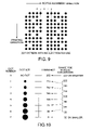
- FIG. 13 is a view showing the absence or presence of an ejection failure (herein, non-ejection) for each nozzle.
- FIG. 14A is a view showing one example of the configuration of an error diffusion matrix.
- FIG. 14B is a view showing diffusion ratios set in respective error diffusion matrices and kinds of error diffusion matrices stored in an error diffusion matrix storage portion.
- FIG. 15 is a flowchart detailing the print data generation processing by the printing device.
- FIG. 16 is a gradation image used in one example.
- FIG. 17 is a view showing a normal error diffusion matrix used in the example.
- FIG. 18 is a view showing the result when the gradation image of FIG. 16 is subjected to quaternary conversion using the error diffusion matrix shown in FIG. 17 .
- FIG. 19 is a view showing the result when the gradation image of FIG. 16 is subjected to quaternary conversion through an error diffusion processing technique of the invention.
- FIG. 20A through FIG. 20C are views used to describe a difference between the printing method of a multi-pass ink-jet printer and the printing method of a line-head ink-jet printer.
- FIG. 21 is a conceptual view showing another example of the structure of the print head.
- FIG. 22A through FIG. 22C are views used to describe weight vectors.
- FIG. 1 through FIG. 14 are views showing the first embodiment of a printing device, a printing device control program, a printing device control method, a print data generation device, a print data generation program, and a print data generation method of the invention.
- FIG. 1 is a block diagram showing the configuration of the printing device 100 of the invention.
- the printing device 100 is a line-head printing device. As is shown in FIG. 1 , it comprises an image data acquisition portion 10 that acquires M-value (M ⁇ 3) image data from an external device or a storage medium, a print data generation portion 11 that generates print data used for a printing portion 12 described below to print an image of the image data on a print medium (for example, a print sheet) by performing N-value (M>N ⁇ 2) conversion processing on the image data acquired from the image data acquisition portion 10 , and the printing portion 12 that prints the image of the image data onto the print medium according to the print data by the ink-jet method.
- M-value M ⁇ 3
- N-value M>N ⁇ 2
- the image data acquisition portion 10 is furnished with a function of acquiring M-value (herein, 256 ⁇ M ⁇ 3) image data for which the grayscale (luminance value) of respective colors (R, G, and B) for each pixel is represented by 8 bits (0 to 255).
- the image data acquisition portion 10 acquires such image data from: an external device via a network, such as the LAN and the WAN; a recording medium, such as a CD-ROM and a DVD-ROM, via an unillustrated driving device, such as a CD drive and a DVD drive, equipped to the printing device 100 ; or a storage device 70 equipped to the printing device 100 described below.
- the image data acquisition portion 10 is able to exert a function of subjecting the M-value RGB data to color conversion processing to be converted to M-value CMYK (in the case of four colors) data corresponding to respective inks in a print head 200 .
- the print data generation portion 11 comprises an N-value conversion portion 11 a , an N-value conversion information storage portion 11 b , an error diffusion portion 11 c , a nozzle information storage portion 11 d , an error diffusion matrix storage portion 11 e , and a print data generation memory 11 f.
- the N-value conversion portion 11 a stores the image data that has been subjected to CMYK color conversion into the print data generation memory 11 f . Also, it selects specific pixel data from the image data and converts the specific pixel data thus selected (hereinafter, referred to as the selected pixel data) to an N value according to an N-value conversion threshold, a dot number corresponding to each dot formation size, and a pixel value (for example, a luminance value) after the N-value conversion corresponding to each dot number, all of which are contained in the N-value conversion information read from the N-value conversion information storage portion 11 b .
- the N-value conversion portion 11 a converts the data indicating the value after the N-value conversion to data that the printing portion 12 can interpret, and stores the converted data in the print data generation memory 11 f by writing the converted data over the original pixel data that has been stored before (the converted data may be stored in another region instead of being written over).
- the N-value conversion referred to herein means the processing to convert M-value (M ⁇ 3) image data (having M kinds of pixel values (pixel data)) to N-value (M>N ⁇ 2) data (having N kinds of numerical values).
- M-value M ⁇ 3 image data (having M kinds of pixel values (pixel data)
- N-value M>N ⁇ 2 data
- a pixel value to be converted is compared with the threshold, and this pixel value is converted to one of two kinds of pre-set numerical values as follows: when the pixel value to be converted is equal to or greater than the threshold, this pixel value is converted to a numerical value “1”, and when the pixel value to be converted is smaller than the threshold, this pixel value is converted to a numerical value “0”.
- the M-value pixel value is compared with N kinds of threshold values, and it is converted to any one numerical value among pre-set N kinds of numerical values in response to the comparison result.
- the N-value conversion information storage portion 11 b stores N-value conversion information made of an N-value conversion threshold corresponding to a dot formation size of each nozzle, the dot number corresponding to each dot formation size, a pixel value (for example, a luminance value) after the N-value conversion corresponding to each dot number, etc.
- the error diffusion portion 11 c reads out nozzle information corresponding to the selected pixel data from the nozzle information storage portion 11 d according to the information and the error of the selected pixel data acquired from the N-value conversion portion 11 a , and judges whether the nozzle corresponding to the selected pixel data is a failing nozzle according to the nozzle information. Upon judging that the nozzle in question is a failing nozzle, it selectively reads out a special error diffusion matrix for avoiding the banding phenomenon caused by this failing nozzle from the error diffusion matrix storage portion 11 e . Meanwhile, upon judging that the nozzle in question is a normal nozzle having no trouble, it reads out a common error diffusion matrix prepared for a normal nozzle (hereinafter, referred to as the normal error diffusion matrix).
- the error diffusion portion 11 c diffuses (distributes) the error to the pixel data that has not been subjected to the N-value conversion processing in the neighborhood of the pixel corresponding to the selected pixel data in the image data stored in the print data generation memory 11 f .
- the image data stored in the print data generation memory 11 f is updated by diffusing the error to the pixel values as diffusion targets in this manner each time the selected pixel data is converted to an N value.
- the error diffusion processing referred to herein is to diffuse an error on the same principle underlying the error diffusion method in the related art.
- “128” is given as the threshold and N-value image data is converted to “0” when the pixel value is smaller than “128” and to “255” when the pixel value is equal to or greater than “128”
- the pixel value of a selected pixel is “101”
- “101” is converted to “0”.
- a difference, “101”, between “0” after the conversion and “101” before the conversion is deemed as an error and diffused to more than one outstanding pixel in the neighborhood according to a predetermined diffusion method.
- a pixel immediately to the right of the selected pixel (for example, having the pixel value of “101”) is converted to “0” as with the selected pixel by the normal binarization processing because it is also smaller than the threshold.
- the pixel value is increased to “128” and becomes equal to the threshold “128”. The pixel value of this pixel is therefore converted to “256”.
- the failing nozzle referred to herein includes all nozzles involved in the occurrence of the banding phenomenon, such as a nozzle having an ink ejection failure, for example, a nozzle incapable of ejecting ink or a nozzle that ejects an abnormal quantity of ink, as well as a nozzle that causes the flight deviation phenomenon due to the displacement of the dot forming position from the ideal position.
- the nozzle information storage portion 11 d stores nozzle information made of information indicating the correspondence between each nozzle N in the print head 200 provided to the printing portion 12 and respective pixel data in the image data, information indicating the absence or presence of an ink ejection failure for each nozzle N, and information indicating the characteristic of each nozzle N, such as information indicating a quantity of flight deviation of each nozzle N.
- the error diffusion matrix storage portion 11 e stores information about the pixel data as diffusion targets, and matrix data that defines diffusion ratios of the error assigned to respective pixel data as the diffusion targets in the form of plural kinds of error diffusion matrices having different diffusion ratios in this embodiment.
- plural kinds of diagonally weighted error diffusion matrices are stored as plural kinds of error diffusion matrices, in which the diffusion ratio is increased for pixel data corresponding to pixels as diffusion targets present in a diagonal direction with respect to the pixel corresponding to the selected pixel data in comparison with other pixel data as diffusion targets for use in the error diffusion processing of the selected pixel data involved in the banding phenomenon.
- plural kinds of normal error diffusion matrices for pixel data that is not involved in the banding phenomenon are also stored.
- the print data generation memory 11 f stores image data having CMYK color information acquired from the image data acquisition portion 10 .
- the print data generation memory 11 f also stores the selected pixel data converted to an N value by writing the converted selected pixel data over the original pixel data according to an instruction from the N-value conversion portion 11 a , and also stores pixel data as diffusion targets to which the error of the selected pixel data has been diffused by writing such pixel data over the original pixel data according to an instruction from the error diffusion portion 11 c .
- the print data is the data for printing used in the printing portion 12 of the ink jet method described below, that is, the data indicating whether a dot of a specific color and a specific size is formed or no dot is formed for each pixel data in the image data.
- FIG. 3 is a partial enlarged bottom view showing the structure of the print head 200 of the invention.
- FIG. 4 is a partial enlarged side elevation of the print head 200 .
- the print head 200 comprises four nozzle modules 50 , 52 , 54 , and 56 .
- black nozzle module 50 plural nozzles N (18 nozzles in the drawing) that eject black (K) ink alone are aligned linearly in the nozzle alignment direction.
- yellow nozzle module 52 plural nozzles N that eject yellow (Y) ink alone are aligned linearly in the nozzle alignment direction.
- magenta nozzle module 54 plural nozzles N that eject magenta (M) ink alone are aligned linearly in the nozzle alignment direction.
- the cyan nozzle module 56 plural nozzles N that eject cyan (C) ink alone are aligned linearly in the nozzle alignment direction.
- the nozzle modules 50 , 52 , 54 , and 56 are arrayed to form one unit in such a manner that the nozzles N labeled with the same numbers in these four nozzle modules are aligned in a straight line along the printing direction (a direction perpendicular to the nozzle alignment direction). That is to say, plural nozzles N that together form the respective nozzle modules are aligned linearly in the nozzle alignment direction, and the nozzles N labeled with the same numbers in the four nozzle modules are aligned linearly in the printing direction.
- FIG. 4 shows a state where the sixth nozzle from the left, the nozzle N 6 , in the black nozzle module 50 among the four nozzle modules 50 , 52 , 54 , and 56 causes the flight deviation phenomenon, and ink is ejected onto a print medium S in a diagonal direction from the nozzle N 6 , thereby forming a dot on the print medium S in the vicinity of a dot ejected from a normal nozzle N 7 adjacent to the nozzle N 6 and formed on the print medium S.
- the printing portion 12 is an ink-jet printer that forms an image made of a large number of dots on the print medium S by ejecting dot-shaped inks from the nozzle modules 50 , 52 , 54 , and 56 provided to the print head 200 while moving either the print medium S or the print head 200 or both shown in FIG. 4 .
- the printing portion 12 includes an unillustrated print head moving mechanism (in the case of a multi-pass type) that moves the print head 200 over the print medium S to reciprocate in the width direction, an unillustrated paper transportation mechanism that moves the print medium (sheet of paper) S, and an unillustrated printing control mechanism that controls ejection of ink from the print head 200 according to the print data.
- the printing device 100 achieves the respective functions, such as the image data acquisition portion 10 , the print data generation portion 11 , and the printing portion 12 by software, and therefore is provided with a computer system that runs the software to control the hardware needed to achieve the respective functions. According to the hardware configuration of the computer system as is shown in FIG.
- a CPU Central Processing Unit
- a RAM Random Access Memory
- main storage device Main Storage
- a ROM Read Only Memory 64 serving as a read-only storage device
- inside/outside buses 68 comprising a PCI (Peripheral Component Interconnect) bus and an ISA (Industrial Standard Architecture) bus.
- PCI Peripheral Component Interconnect
- ISA Industry Standard Architecture
- an external storage device (Secondary Storage) 70 such as an HDD
- an output device 72 such as a printing portion 20 , a CRT, and an LCD monitor
- an input device 74 such as an operation panel, a mouse, a keyboard, and a scanner, and a network cable L to enable communications with an unillustrated printing instruction device
- I/F input/output interface
- a system program such as BIOS, pre-installed in the ROM 64 down loads various kinds of exclusive-use computer programs pre-installed in the ROM 64 or various kinds of exclusive-use computer programs installed in the storage device 70 via a recording medium, such as a CD-ROM, a DVD-ROM, and a flexible disc (FD), or via a communication network, such as the Internet, to the RAM 62 .
- a recording medium such as a CD-ROM, a DVD-ROM, and a flexible disc (FD)
- FD flexible disc
- a communication network such as the Internet
- the printing device 100 activates a specific program pre-installed in a specific region of the ROM 64 by the CPU 60 , and executes the printing processing detailed in the flowchart of FIG. 5 according to the program.
- the print head 200 that forms dots is normally able to form dots of more than one color, for example, dots of four or six colors, simultaneously.
- descriptions will be given on the assumption that each dot is formed by a (monochrome) print head 200 of one color (monochrome image).
- FIG. 5 is a flowchart detailing the printing processing by the printing device 100 .
- Step S 100 when the CPU 60 starts the printing processing, the printing device 100 proceeds to Step S 100 .
- Step S 100 whether the image data acquisition portion 10 has received a printing instruction, either in the form of printing instruction information sent from a linked-external device via the network cable L or in the form of printing instruction information inputted via the input device 74 , is judged. Upon judgment that the printing instruction has been received (Yes), the flow proceeds to Step S 102 ; otherwise (No), the judgment processing is repeated until the printing instruction is received.
- the image data acquisition portion 10 performs processing to acquire image data corresponding to the printing instruction from the external device, a recording medium, such as a CD-ROM and a DVD-ROM, or the storage device 70 ; such as an HDD, as described above. Subsequently, whether the image data has been acquired is judged. Upon judgment that the image data has been acquired (Yes), the flow proceeds to Step S 104 ; otherwise (No), a response, “printing is impossible”, is returned to the sender of the printing instruction. The flow then returns to Step S 100 by canceling the printing processing for this printing instruction.
- the image data is the data made of plural M-value pixel data arrayed in a matrix fashion. The row direction coincides with the nozzle alignment direction of the print head 200 , and the column direction coincides with the printing direction of the print head 200 .
- Step S 104 in a case where the M-value image data acquired in Step S 102 is image data having color information other than CMYK, the image data acquisition portion 10 converts the image data to the image data having the color information of CMYK (hereinafter, referred to as CMYK image data), and transmits the CMYK image data to the print data generation portion 11 .
- CMYK image data the image data having the color information other than CMYK
- the image data having the color information other than CMYK is subjected to CMYK conversion before it is transmitted, whereas the CMYK image data is transmitted intact.
- Step S 106 when the M-value CMYK image data is acquired from the image data acquisition portion 10 , the print data generation portion 11 generates the print data by performing the N-value conversion and the error diffusion processing to the acquired image data. The flow then proceeds to Step S 108 .
- Step S 108 the print data generation portion 11 outputs the print data generated in Step S 106 to the printing portion 12 .
- the flow then proceeds to Step S 110 .
- Step S 110 the printing portion 12 executes printing processing according to the print data from the print data generation portion 11 .
- the flow then returns to Step S 100 .
- Step S 106 The print data generation processing in Step S 106 will now be described in detail with reference to FIG. 6 .
- FIG. 6 is a flowchart detailing the print data generation processing by the printing device 100 .
- the print data generation processing is the processing according to which the following are performed. That is, the selected pixel data is subjected to the N-value conversion processing, and whether the nozzle N corresponding to the selected pixel data is a failing nozzle is judged. An appropriate error diffusion matrix for the pixel data corresponding to the failing nozzle is selected from the error diffusion matrix storage portion lie according to the judgment result, and the error diffusion processing is performed using the error diffusion matrix thus selected. The print data is then generated according to the image data that has been subjected to the N-value conversion processing and the error diffusion processing.
- Step S 106 the flow proceeds to Step S 200 as is shown in FIG. 6 .
- Step S 200 the N-value conversion portion 11 a judges whether the M-value CMYK image data has been acquired from the image data acquisition portion 10 . Upon judgment that the CMYK image data has been acquired (Yes), the acquired CMYK image is stored in the print data generation memory 11 f . The flow then proceeds to Step S 202 . Otherwise (No), the judgment processing is repeated until the CMYK image data is acquired.
- Step S 202 the N-value conversion portion 11 a acquires N-value conversion information by reading out the N-value conversion information from the N-value conversion information storage portion 11 b , and storing the read N-value conversion information in a specific region of the RAM 62 .
- the flow then proceeds to Step S 204 .
- Step S 204 the N-value conversion portion 11 a selects pixel data that has not been subjected to the N-value conversion processing in the CMYK image data stored in the print data generation memory 11 f . The flow then proceeds to Step S 206 .
- Step S 206 the N-value conversion portion 11 a converts the selected pixel data selected in Step S 204 to an N value according to the N-value conversion information acquired in Step S 202 , and converts the value after the N-value conversion to data indicating the dot size formed by the nozzle for the value after the N-value conversion in the format that the printing portion 12 can interpret.
- the selected pixel data in the CMYK image data stored in the print data generation memory 11 f is thus updated to the converted data.
- the flow then proceeds to Step S 208 .
- Step S 208 the N-value conversion portion 11 a calculates a difference between the pixel value before the N-value conversion and the pixel value after the N-value conversion of the selected pixel data according to the result of the N-value conversion in Step S 206 , and transmits the calculation result as an error to the error diffusion portion 11 c together with information about the selected pixel data. The flow then proceeds to Step S 210 .
- Step S 210 upon acquisition of the error calculated in Step S 208 and the information about the selected pixel data corresponding to the error from the N-value conversion portion 11 a , the error diffusion portion 11 c acquires nozzle information corresponding to the selected pixel data by reading out the nozzle information from the nozzle information storage portion 11 d and storing the read nozzle information in a specific region of the RAM 62 .
- the flow then proceeds to Step S 212 . Thereafter, by searching for the nozzle information corresponding to the selected pixel data through the nozzle information stored in the RAM 62 first, it is possible to accelerate the acquisition processing of the pixel data using the same nozzle information.
- Step S 212 the error diffusion portion 11 c judges whether the nozzle N corresponding to the selected pixel data is a failing nozzle on the basis of the nozzle information acquired in Step S 210 . Upon judgment that the nozzle N is a failing nozzle (Yes), the flow proceeds to Step S 214 ; otherwise (No), the flow proceeds to Step S 220 .
- the error diffusion portion 11 c selectively reads out the diagonally weighted error diffusion matrix from the error diffusion matrix storage portion 11 e .
- the flow then proceeds to Step S 216 .
- plural kinds of matrix data having different diffusion ratios are stored in the error diffusion matrix storage portion 11 e , and the diagonally weighted error diffusion matrix can be selected from these plural diagonally weighted error diffusion matrices in various manners, for example, it may be selected randomly or in a predetermined sequential order for each selected pixel data, or it may be selected appropriately in response to the condition of the failing nozzle corresponding to the selected pixel.
- Step S 216 the error diffusion portion 11 c diffuses the error of the selected pixel data acquired in Step S 210 according to the error diffusion matrix selected in Step S 214 or S 220 to pixel data as diffusion targets that has not been subjected to the N-value conversion processing in the image data stored in the print data generation memory 11 f , and thereby updates the pixel data as the diffusion targets.
- the flow then proceeds to Step S 218 .
- Step S 218 the N-value conversion portion 11 a judges whether the N-value conversion processing has been completed for all the pixel data. Upon judgment that the processing has been completed (Yes), the sequence of processing is ended and the device returns to the original processing; otherwise (No), the flow returns to Step S 204 .
- Step S 220 when the flow proceeds to Step S 220 upon judgment that the nozzle corresponding to the selected pixel data is not a failing nozzle in Step S 212 , the error diffusion portion 11 c selectively reads out the normal error diffusion matrix from the error diffusion matrix storage portion 11 e .
- the flow then proceeds to Step S 216 .
- plural kinds of matrix data having different diffusion ratios are stored in the error diffusion matrix storage portion 11 e , and the normal error diffusion matrix can be selected from these error diffusion matrices in various manners, for example, the one corresponding to each pixel data may be selected, or it may be selected randomly or in the predetermined sequential order for each selected pixel data.
- FIG. 7 is a view showing one example of a dot pattern formed by the black nozzle module 50 alone having no so-called failing nozzle.
- FIG. 8 is a view showing one example of a dot pattern formed by the black nozzle module 50 when the nozzle N 6 causes the flight deviation phenomenon.
- FIG. 9 is a view showing one example of a dot pattern formed by the black nozzle module 50 when the nozzle N 6 has an ink ejection failure (in the drawing, non-ejection).
- FIG. 10 is a view showing one example of information about an N value and information about the threshold for each N value regarding the dot size.
- FIG. 11A is a view showing absolute ejection accuracy information (information about a quantity of flight deviation) for each nozzle.
- FIG. 11B is a view showing relative ejection accuracy information for each nozzle.
- FIG. 12 is a view used to describe the reason why the relative ejection accuracy information is necessary.
- FIG. 13 is a view showing the absence or presence of an ejection failure (in the drawing, non-ejection) for each nozzle.
- FIG. 14A is a view showing one example of the configuration of the error diffusion matrix.
- FIG. 14B is a view showing the diffusion ratios of the respective error diffusion matrices and the kinds of error diffusion matrices stored in the error diffusion matrix storage portion 11 e.
- the banding phenomenon such as a white streak and a dark streak, resulting from displacement of nozzle intervals will not occur in the dot pattern formed by the black nozzle module 50 having no failing nozzle.
- dots formed by the nozzle N 6 is displaced by a distance a toward dots formed by a normal nozzle N 7 immediately to the right of the nozzle N 6 . Consequently, a white streak occurs between dots formed by the nozzle N 6 and dots formed by a nozzle N 5 immediately to the left of the nozzle N 6 .
- dots formed by the nozzle N 6 and dots formed by the nozzle N 7 immediately to the right come closer by the distance a as dots formed by the nozzle N 6 are displaced by the distance a due to the flight deviation. Dots formed by these nozzles therefore become denser (dots may overlap), and this portion appears noticeably as a dark streak. The quality of the printed matter is thus deteriorated considerably.
- dots that should have been formed are not formed due to an ink ejection failure (non-ejection) of the nozzle N 6 , and a white streak occurs between dots formed by the nozzle N 5 and dots formed by the nozzle N 7 .
- the white streak becomes more noticeable in the printed matter printed at a uniform density, and in particular, in a combination of a white print sheet and black ink having a significant difference in density. The quality of the printed matter is thus deteriorated extremely.
- the printing device 100 becomes able to produce print data to make a white streak or a dark streak less noticeable by subjecting the pixel data corresponding to a nozzle that causes the flight deviation or a nozzle having an ejection failure, that is, a failing nozzle to the error diffusion processing using the diagonally weighted error diffusion matrix as described above.
- the image data acquisition portion 10 upon receipt of the printing instruction information from an external device (Step S 100 ), acquires M-value image data corresponding to the printing instruction information from the external device as the sender of the printing instruction information (Step S 102 ).
- the image data is converted to M-value CMYK image data, and the CMYK image data is transmitted to the print data generation portion 11 (Step S 104 ).
- the print data generation portion 11 starts to perform the print data generation processing (Step S 106 ).
- the N-value conversion portion 11 a first acquires the CMYK image data from the image data acquisition portion 10 , and then stores the CMYK image data thus acquired in the print data generation memory 11 f (Step S 200 ). Subsequently, the N-value conversion portion 11 a reads out the N-value conversion information from the N-value conversion information storage portion 11 b , and stores the read N-value conversion information in a specific region of the RAM 62 (Step S 200 ).
- the N-value conversion portion 11 a Upon acquisition of the N-value conversion information, the N-value conversion portion 11 a selects pixel data that has not been subjected to the N-value conversion processing from the CMYK image data stored in the print data generation memory 11 f (Step S 204 ). The N-value conversion portion 11 a then converts the value of the M-value selected pixel data to an N value according to the acquired N-value conversion information. Also, it converts the value after the N-value conversion to data indicating the dot number of a dot formed by the nozzle for this value after the N-value conversion in the format that the printing portion 12 can interpret. The selected pixel data in the CMYK image data stored in the print data generation memory 11 f is thus updated to the converted data (Step S 206 ).
- the N-value conversion is performed as follows.
- the original pixel value (luminance value (or density value)) of the selected pixel data is 8 bits with 256 grayscale levels, as is shown in FIG. 10
- the pixel value is converted to “0”, and “7” is given as the N value corresponding to the dot number.
- the original pixel value is equal to “32” or greater and smaller than “64”
- the pixel value is converted to “36”
- “6” is given as the N value corresponding to the dot number.
- the pixel value When the original pixel value is equal to or greater than “64” and smaller than “96”, the pixel value is converted to “73”, and “5” is given as the N value corresponding to the dot number. Likewise, when the original pixel value is equal to or greater than “96” and smaller than “128”, the pixel value is converted to “109”, and “4” is given as the N value corresponding to the dot number. When the original pixel value is equal to or greater than “128” and smaller than “159”, the pixel value is converted to “146”, and “3” is given as the N value corresponding to the dot number.
- the pixel value When the original pixel value is equal to or greater than “159” and smaller than “191”, the pixel value is converted to “182”, and “2” is given as the N value corresponding to the dot number.
- the pixel value When the original pixel value is equal to or greater than “191” and smaller than “223”, the pixel value is converted to “219”, and “1” is given as the N value corresponding to the dot number.
- the pixel value When the original pixel value is equal to or greater than “223”, the pixel value is converted to “255”, and “0” is given as the N value corresponding to the dot number.
- the example described above is a case where the luminance value is adopted as the pixel value, and when the density value is adopted as the pixel value, the value takes values in inverse order of the luminance values (for example, a value obtained by subtracting each luminance value from “255”).
- the N-value conversion portion 11 a After the N-value conversion portion 11 a converted the selected pixel data to the N value, it calculates a difference between the luminance value before the conversion and the luminance value after the conversion corresponding to the dot number of the selected pixel data as an error, and transmits the error thus calculated to the error diffusion portion 11 c together with the information about the selected pixel data (Step S 208 ).
- the error diffusion portion 11 c acquires nozzle information corresponding to the selected pixel data by reading out the nozzle information from the nozzle information storage portion 11 d according to the acquired information about the selected pixel data and storing the nozzle information in a specific region of the RAM 62 (Step S 210 ). The error diffusion portion 11 c then judges whether the nozzle corresponding to the selected pixel data is a failing nozzle according to the nozzle information thus acquired (Step S 212 ).
- the judgment processing of a failing nozzle is performed according to the absolute ejection accuracy information shown in FIG. 11A , the relative ejection accuracy information shown in FIG. 11B , and ejection absence or presence information shown in FIG. 13 .
- the occurrence of flight deviation is not judged when a difference (relative ejection accuracy) between the ideal position of the nozzle N corresponding to the selected pixel data and the ideal position of a nozzle N+1 adjacent to the nozzle N is ⁇ 0 ⁇ m or less than a specific value.
- the reason why the failing nozzle is judged using not only the absolute ejection accuracy but also the relative ejection accuracy as above is because as is shown in FIG. 12 , for example, in a case where all of three sequentially aligned nozzles cause the flight deviation of the same quantity in the same direction, when the error diffusion processing is performed on the pixel data corresponding to these nozzles with the use of the special error diffusion matrix for avoiding banding (for example, the diagonally weighted error diffusion matrix), there is a possibility that the image quality in the printing result is deteriorated.
- the nozzle is judged as being a failing nozzle incapable of ejecting ink.
- the nozzle is judged as being a normal nozzle.
- the diagonally weighted error diffusion matrix is selected from the error diffusion matrix storage portion 11 f (Step S 214 ).
- a normal error diffusion matrix is selected from the error diffusion matrix storage portion 11 f (Step S 220 ).
- the error diffusion matrix of this embodiment is a matrix having the diffusion content as follows. That is, let x 1 through x 4 be error diffusion ratios assigned to four pixel data as diffusion targets, then the error is diffused to the pixel data as a diffusion target at the lower left with respect to the selected pixel data (pixel of interest in FIG. 14A ) at the diffusion ratio, x 1 . The error is diffused to the pixel data as a diffusion target immediately below at the diffusion ratio, x 2 . The error is diffused to the pixel data as a diffusion target at the lower right at the diffusion ratio, x 3 . The error is diffused to the pixel data as a diffusion target immediately to the right at the diffusion ratio, x 4 .
- the error diffusion matrix is selected as follows. That is, when the nozzle N corresponding to the selected pixel data is a failing nozzle, as is shown in FIG. 14B , the error diffusion matrix is selected from diagonally weighted error diffusion matrices identified with the matrix ID, such as those identified with ID 2 , ID 4 , and ID 8 . On the other hand, when the nozzle N corresponding to the selected pixel data is a normal nozzle, the error diffusion matrix is selected from the normal error diffusion matrices identified with the matrix ID, such as those identified with ID 1 , ID 3 , and ID 5 through ID 7 .
- Numerical values corresponding to the diffusion ratios x 1 through x 4 in FIG. 14B represent the diffusion ratios, and descriptions will be given using the diagonally weighted error diffusion matrix identified with ID 2 as an example.
- x 4 5.
- the error to be diffused (value to be distributed) is calculated by multiplying the error by a numerator, which is one of the numerical values of x 1 through x 4 .
- the normal error diffusion matrix identified with ID 7 is compared with the diagonally weighted error diffusion matrix identified with ID 2 , it is understood that the error is diffused more in the diagonal direction (the diagonally right down direction) with the diagonally weighted error diffusion matrix identified with ID 2 .
- the error diffusion ratio is larger for the pixel data in the diagonal direction (pixel data corresponding to x 1 or x 3 in FIG. 14A ) in any diagonally weighted error diffusion matrix than in any normal error diffusion matrix.
- one diagonally weighted error diffusion matrix or one normal error diffusion matrix is selected randomly for each selected pixel data among plural diagonally weighted error diffusion matrices and plural normal error diffusion matrices pre-stored in the error diffusion matrix storage portion 11 f .
- the reason why the error diffusion matrix is selected randomly is because a better image quality can be obtained in the printing result by diffusing the error with the use of plural kinds of randomly selected error diffusion matrices than by performing error diffusion with the use of a fixed error diffusion matrix without variation.
- the errors calculated with the diffusion ratios set in the selected error diffusion matrix as shown in FIG. 14B are diffused to the pixel data as diffusion targets at the lower left, immediately below, at the lower right, and immediately to the right with respect to the selected pixel data (data of the pixel of interest in FIG. 14A ) in the CMYK image data stored in the print data generation memory 11 f as is shown in FIG. 14A .
- the CMYK image data stored in the print data generation memory 11 f is thus updated.
- the pixel value of pixel data that has not been subjected to the N-value conversion processing in the neighborhood of the selected pixel data is updated to the one that reflects the error caused by the N-value conversion as the result of the diffusion processing by the error diffusion portion 11 c .
- the N-value conversion and the error diffusion processing with the use of the error diffusion matrix selected according to the nozzle information are performed successively on the outstanding pixel data updated as described above.
- the print data generation processing ends when the N-value conversion and the error diffusion processing have been performed on all the pixel data in the CMYK image data stored in the print data generation memory 11 f (branching to Yes in Step S 218 ).
- each pixel value in the CMYK image data after the N-value conversion and the error diffusion processing stored in the print data generation memory 11 f is now the data indicating the dot number corresponding to each dot formation size in the data format that the printing portion 12 can interpret, and it is the print data that can drive the print head 200 in the printing portion 12 .
- the print data generation portion 11 therefore outputs the print data thus generated to the printing portion 12 , and deletes the print data that has been stored before in the print data generation memory 11 f (Step S 108 ).
- the printing portion 12 forms (prints) dots of sizes corresponding to the respective dot numbers on the print medium using the black nozzle module 50 according to the print data thus acquired (Step S 110 ).
- a technical method of controlling the dot sizes can be readily achieved by controlling a quantity of ejected ink by varying a voltage applied to the piezo actuators.
- the image data acquisition portion 10 corresponds to the image data acquisition portion in the first aspect or the twenty-fifth aspect.
- the N-value conversion processing to convert the M-value pixel value of the selected pixel data to an N value by the N-value conversion portion 11 a and the N-value conversion information storage portion 11 b corresponds to the N-value conversion processing portion in the first aspect or the twenty-fifth aspect.
- the error diffusion portion 11 c corresponds to the error diffusion portion in any one the first, fifth, sixth, twenty-fifth, twenty-ninth, and thirtieth aspects.
- the nozzle information storage portion 11 d corresponds to the nozzle information storage portion in the first aspect or the twenty-fifth aspect.
- the error diffusion matrix storage portion 11 e corresponds to the error diffusion matrix storage portion in any one of the first, tenth, eighteenth, twenty-fifth, thirty-second, and the fortieth aspects.
- the selecting processing of the outstanding pixel data by the N-value conversion portion 11 a corresponds to the pixel data selecting portion in the first aspect or the twenty-fifth aspect.
- the processing to convert the data after the N-value conversion to data indicating the dot number of the dot formed by the nozzle in the format that the printing portion 12 can interpret by the N-value conversion portion 11 a corresponds to print data generation portion in the first aspect or the twenty-fifth aspect.
- the printing portion 12 corresponds to the printing portion in the first aspect.
- Steps S 102 and S 104 correspond to the acquiring of the image data in any one of the tenth, eighteenth, thirty-second, and fortieth aspects.
- Steps S 202 , S 206 , and S 208 correspond to the performing of the N-value conversion processing in any one of the tenth, sixteenth, eighteenth, thirty-second, thirty-eighth, and fortieth aspects and to the generating of the print data in any one of the tenth, eighteenth, thirty-second, and fortieth aspects.
- Step S 204 corresponds to the selecting of pixel data in any one of the tenth, eighteenth, thirty-second, and fortieth aspects.
- Steps S 210 through S 216 , and S 220 correspond to the diffusing of the error in any one of the tenth, fourteenth, fifteenth, sixteenth, eighteenth, twenty-second, twenty-third, thirty-second, thirty-sixth, thirty-seventh, fortieth, forty-fourth, and forty-fifth aspects.
- Step S 110 corresponds to the printing in the tenth aspect or the eighteenth aspect.
- FIG. 15 is a view showing the second embodiment of the printing device, the printing device control program, the printing device control method, the print data generation device, the print data generation program, and the print data generation method of the invention.
- the configurations of the printing device and the computer system of the second embodiment are the same as their counterparts of the first embodiment shown in FIG. 1 and FIG. 2 , respectively.
- the print data generation processing performed in Step S 106 in FIG. 5 of the first embodiment is replaced with the one in FIG. 15 .
- the generation principle underlying the print data generation processing of FIG. 15 is the same as the one in the first embodiment except that the selected pixel data corresponding to a nozzle having an ink ejection failure is not converted to an N value, and instead the value of the original pixel data, which is deemed as an error, is diffused to the pixel data as diffusion targets in the neighborhood with the use of a special error diffusion matrix for avoiding the banding stored in the error diffusion matrix storage portion 11 e .
- the portion different from the first embodiment will be described, and the description of the same portion will not be repeated herein.
- Step S 106 in the second embodiment will be described in detail with reference to FIG. 15 .
- FIG. 15 is a flowchart detailing the print data generation processing by the printing device 100 .
- This print data generation processing is the processing according to which the followings are performed. Firstly, whether the nozzle N corresponding to the selected pixel data is a failing nozzle is judged. When the nozzle N is a failing nozzle that causes the flight deviation, an error is calculated by performing the N-value conversion. On the other hand, when the nozzle N is a failing nozzle having an ink ejection failure, the N-value conversion is not performed, and instead, the pixel value of the original pixel data is used as an error. Further, an appropriate error diffusion matrix for the pixel data corresponding to the failing nozzle is selected from the error diffusion matrix storage portion 11 e according to the judgment result. The error diffusion processing is then performed using the error diffusion matrix thus selected. The print data is finally generated according to the image data having undergone the foregoing processing. When the print data generation processing is performed in Step S 106 , as is shown in FIG. 15 , the flow proceeds to Step S 300 .
- Step S 300 the N-value conversion portion 11 a judges whether the M-value CMYK image data has been acquired from the image data acquisition portion 10 is judged. Upon judgment that the CMYK image data has been acquired (Yes), the acquired CMYK image data is stored in the print data generation memory 11 f . The flow then proceeds to Step S 302 . Otherwise (No), the judgment processing is repeated until the CMYK image data is acquired.
- the N-value conversion portion 11 a acquires the N-value conversion information by reading out N-value conversion information from the N-value conversion information storage portion 11 b and storing the read N-value conversion information in a specific region of the RAM 62 . The flow then proceeds to Step S 304 .
- Step S 304 the N-value conversion portion 11 a selects pixel data that has not been subjected to the N-value conversion processing in the CMYK image data stored in the print data generation memory 11 f . The flow then proceeds to Step S 306 .
- Step S 306 the N-value conversion portion 11 a acquires nozzle information corresponding to the selected pixel data by reading out the nozzle information from the nozzle information storage portion 11 d and storing the read nozzle information in a specific region of the RAM 62 . The flow then proceeds to Step S 308 .
- Step S 308 the N-value conversion portion 11 a judges whether the nozzle N corresponding to the selected pixel data has an ink ejection failure according to the nozzle information acquired in Step S 306 . Upon judgment that the nozzle N has an ink ejection failure (Yes), the flow proceeds to Step S 310 ; otherwise (No), the flow proceeds to Step S 318 .
- the N-value conversion portion 11 a converts the pixel value of the selected pixel value to the lowest density value (for example, the density value of “0” or the luminance value of “255”), and generates data indicating “no dot” corresponding to the lowest density value in the format that the printing portion 12 can interpret.
- the selected pixel data in the CMYK image data stored in the print data generation memory 11 f is then updated to the data thus generated.
- a difference between the pixel value before the conversion and the pixel value after the conversion is calculated as an error, and the error and the information about the selected pixel data (including the information indicating the ejection failure) are transmitted to the error diffusion portion 11 c .
- the flow then proceeds to Step S 312 .
- Step S 310 the pixel data corresponding to the dot formed by the nozzle having an ink ejection failure was converted to the lowest density value indicating “no dot” in FIG. 10 by way of example.
- the image in the printing result may be viewed locally, and when a dot size for an image in the converted portion is too small to be perceived by humans, the pixel data may be converted, for example, to a luminance value in the range of forming a dot as small as those with the dot number 1 or the dot number 2 shown in FIG. 10 instead of the value indicating “no dot”.
- Step S 312 upon acquisition of the error calculated in Step S 310 and the information about the selected pixel data corresponding to the error from the N-value conversion portion 11 a , the error diffusion portion 11 c selectively reads out the diagonally weighted error diffusion matrix from the error diffusion matrix storage portion 11 e . The flow then proceeds to Step S 314 .
- Step S 314 the error diffusion portion 11 c diffuses the error of the selected pixel data acquired in Step S 312 or Step S 322 with the use of the error diffusion matrix selected in Step S 312 or Step S 324 to the pixel data as diffusion targets in the image data stored in the print data generation memory 11 f , and thereby updates the pixel data as diffusion targets.
- the flow then proceeds to Step S 316 .
- Step S 316 the N-value conversion portion 11 a judges whether the N-value conversion processing has been completed for all the pixel data. Upon judgment that the N-value conversion has been completed (Yes), the sequence of processing is ended and the device is returned to the original processing; otherwise (No), the flow returns to Step S 304 .
- Step S 318 the selected pixel data selected in Step S 304 is converted to an N value according to the N-value conversion information acquired in Step S 302 . Also, the value after the N-value conversion is converted to data indicating the dot size to be formed in the format that the printing portion 12 can interpret. The selected pixel data in the CMYK image data stored in the print data generation memory 11 f is thus updated to the converted data. The flow then proceeds to Step S 320 .
- Step S 320 the N-value conversion portion 11 a calculates a difference between the pixel value before the N-value conversion and the pixel value after the N-value conversion of the selected pixel data according to the result of the N-value conversion in Step S 318 , and transmits the calculation result as an error to the error diffusion portion 11 c together with the information about the selected pixel data. The flow then proceeds to Step S 322 .
- Step S 322 the error diffusion portion 11 c judges whether the nozzle N corresponding to the selected pixel data is a failing nozzle that causes the flight deviation according to the nozzle information stored in the RAM 62 . Upon judgment that the nozzle N is a failing nozzle (Yes), the flow proceeds to Step S 324 ; otherwise (No), the step proceeds to Step S 326 .
- Step S 324 the error diffusion portion 11 c selectively reads out the diagonally weighted error diffusion matrix from the error diffusion matrix storage portion 11 e .
- the flow then proceeds to Step S 314 .
- Step S 326 when the flow proceeds to Step S 326 because it is judged in Step S 322 that the nozzle corresponding to the selected pixel data is not a failing nozzle, the error diffusion portion 11 c selectively reads out the normal error diffusion matrix from the error diffusion matrix storage portion 11 e . The flow then proceeds to Step S 314 .
- dots formed by the nozzle N 6 in the black nozzle module 50 are displaced by a distance a toward dots formed by the normal nozzle N 7 immediately to the right, and as a result, a white streak occurs between dots formed by the nozzle N 6 and dots formed by the nozzle N 5 immediately to the left.
- the nozzle N 6 in the black nozzle module 50 has an ink ejection failure, and dots that should have been formed are not formed. As a result, a white streak occurs between dots formed by the nozzle N 5 and dots formed by the nozzle N 7 .
- the same processing as the first embodiment is performed on the pixel data corresponding to the nozzle that causes the flight deviation, whereas the N-value conversion is not performed on the pixel data corresponding to the nozzle having an ejection failure, and instead, the error diffusion processing is performed with the use of the diagonally weight error diffusion matrix by deeming the pixel value itself as an error.
- the printing device 100 is therefore able to produce print data that can make a white streak or a dark streak less noticeable.
- the N-value conversion portion 11 a acquires the CMYK image data from the image data acquisition portion 10 , and stores the acquired CMYK image data in the print data generation memory 11 f (Step S 300 ). Subsequently, the N-value conversion portion 11 a reads out the N-value conversion information from the N-value conversion information storage portion 11 b , and stores the read N-value conversion information in a specific region of the RAM 62 (Step S 302 ).
- the N-value conversion portion 11 a Upon acquisition of the N-value conversion information, the N-value conversion portion 11 a selects pixel data that has not been subjected to the N-value conversion processing in the CMYK image data stored in the print data generation memory 11 f (Step S 304 ). The N-value conversion portion 11 a then reads out nozzle information corresponding to the selected pixel data from the nozzle information storage portion 11 d and stores the read nozzle information in a specific region of the RAM 62 (Step S 306 ). Subsequently, the N-value conversion portion 11 a judges whether the nozzle N has an ink ejection failure according to the acquired nozzle information indicating the absence or presence of an ejection failure in the nozzle N corresponding to the selected pixel data as shown in FIG. 13 in the first embodiment (Step S 308 ).
- the N-value conversion portion 11 a Upon judgment that the nozzle N corresponding to the selected pixel data has an ejection failure, the N-value conversion portion 11 a converts the pixel value of the selected pixel data to the lowest density value (for example, the luminance value of “255”), and generates data indicating “no dot” corresponding to the lowest density value in the format that the printing portion 12 can interpret. The N-value conversion portion 11 a then updates the selected pixel data stored in the print data generation memory 11 f to the data thus generated.
- the lowest density value for example, the luminance value of “255”
- the N-value conversion portion 11 a calculates a difference between the pixel value before the conversion and the pixel value after the conversion (luminance value of “255”) of the selected pixel data as the error for the error diffusion, and transmits the error and the information about the selected pixel data (including the information indicating the presence of an ejection failure) to the error diffusion portion 11 c (Step S 310 ).
- the error diffusion portion 11 c selects the diagonally weighted error diffusion matrix from the error diffusion matrix storage portion 11 f (Step S 312 ). Subsequently, as is shown in FIG. 14A in the first embodiment, the error diffusion portion 11 c diffuses the error to the pixel data as diffusion targets at the lower left, immediately below, at the lower right, and immediately to the right with respect to the selected pixel data (the data of the pixel of interest in FIG.
- Step S 314 in the CMYK image data stored in the print data generation memory 11 f at the diffusion ratios set in the diagonally weighted error diffusion matrix as shown in FIG. 14B , thereby updating the CMYK image data (pixel data as diffusion targets) stored in the print data generation memory 11 f (Step S 314 ).
- the N-value conversion portion 11 a Upon judgment that the nozzle N corresponding to the selected pixel data has no ejection failure, the N-value conversion portion 11 a converts the selected pixel data to an N value according to the N-value conversion information thus acquired, and converts the value after the N-value conversion to data indicating the dot number of the dot formed by the nozzle for this value after the N-value conversion in the format that the printing portion 12 can interpret, thereby updating the selected pixel data in the CMYK image data stored in the print data generation memory 11 f (Step S 318 ).
- the N-value conversion portion 11 a calculates an error between the luminance value before the conversion and the luminance value after the conversion corresponding to the dot number of the selected pixel data, and transmits the error thus calculated and the information about the selected pixel data to the error diffusion portion 11 c (Step S 320 ).
- the error diffusion portion 11 c subsequently judges whether the nozzle N corresponding to the selected pixel data causes the flight deviation according to the absolute ejection accuracy information and the relative ejection accuracy information about the nozzle N shown in FIG. 11A and FIG. 11B , respectively (Step S 322 ). Upon judging the occurrence of the flight deviation (branching to Yes in Step S 322 ), the error diffusion portion 11 c selects the diagonally weighted error diffusion matrix from the error diffusion matrix storage portion 11 f (Step S 324 ).
- the error diffusion portion 11 c selects the normal error diffusion matrix from the error diffusion matrix storage portion 11 f (Step S 326 ).
- the errors calculated are diffused to the pixel data as diffusion targets at the lower left, immediately below, at the lower right, and immediately to the right with respect to the selected pixel data (data of the pixel of interest in FIG. 14A ) in the CMYK image data stored in the print data generation memory 11 f as is shown in FIG. 14A at the diffusion ratios set in the selected error diffusion matrix shown in FIG. 14B .
- the CMYK image data stored in the print data generation memory 11 f is thus updated.
- the print data generation processing ends when the N-value conversion and the error diffusion processing have been performed on all the pixel data in the CMYK image data stored in the print data generation memory 11 f (branching to Yes in Step S 316 ).
- the N-value conversion and the error diffusion processing are performed to the pixel data corresponding to the nozzle having an ink ejection failure on the assumption that dots are formed
- the N-value conversion is not performed on the assumption that dots will not be formed and the grayscale of the pixel data in a portion where a dot is not formed is compensated with the pixel data in the neighborhood.
- the pixel value of the pixel data for which a dot is not formed is used as the error, and is diffused to outstanding pixel data in the neighborhood.
- the image data acquisition portion 10 corresponds to the image data acquisition portion in the first aspect or the twenty-fifth aspect.
- the N-value conversion processing to convert an M-value pixel value of the selected pixel data to an N value by the N-value conversion portion 11 a and the N-value information storage portion 11 b corresponds to the N-value conversion portion in any one of the first, seventh, twenty-fifth, and thirty-first aspects.
- the error diffusion portion 11 c corresponds to the error diffusion portion in any one of the first, fifth, seventh, twenty-fifth, twenty-ninth, and thirty-first aspects.
- the nozzle information storage portion 11 d corresponds to the nozzle information storage portion in the first aspect or the twenty-fifth aspect.
- the error diffusion matrix storage portion lie corresponds to the error diffusion matrix storage portion in any one of the first, tenth, eighteenth, twenty-fifth, thirty-second, and fortieth aspects.
- the processing to select outstanding pixel data by the N-value conversion portion 11 a corresponds to the pixel data selecting portion in the first aspect or the twenty-fifth aspect.
- the processing to convert the data after the N-value conversion to the data indicating the dot number of a dot formed by the nozzle in the format that the printing portion 12 can interpret and the processing to generate the data indicating “no dot” corresponding to the selected pixel data converted to the lowest density value in the format that the printing portion 12 can interpret by the N-value conversion portion 11 a correspond to the print data generation portion in the first aspect or the twenty-fifth aspect.
- the printing portion 12 corresponds to the print portion in the first aspect.
- Steps S 102 and S 104 correspond to the acquiring of the image data in any one of the tenth, eighteenth, thirty-second, and fortieth aspects.
- Steps S 202 , S 206 , and S 208 correspond to the performing of the N-value conversion processing in any one of the tenth, sixteenth, eighteenth, twenty-fourth, thirty-second, thirty-eighth, fortieth, and forty-sixth aspects and to the generating of the print data in any one of the tenth, eighteenth, thirty-second, and fortieth aspects.
- Step S 204 corresponds to the selecting of the pixel data in any one of the tenth, eighteenth, thirty-second, and fortieth aspects.
- Steps S 210 through S 216 and S 220 correspond to the diffusing of the error in any one of the tenth, fourteenth, sixteenth, eighteenth, twenty-second, twenty-fourth, thirty-second, thirty-sixth, thirty-eighth, fortieth, forty-fourth, and forty-sixth aspects.
- Step S 110 corresponds to the printing in the tenth aspect or the eighteenth aspect.
- FIG. 16 shows a gradation image used in this example.
- FIG. 17 is a normal error diffusion matrix used in the error diffusion technique in the related art.
- FIG. 18 is a view showing the result when the gradation image of FIG. 16 is subjected to the quaternary conversion using the error diffusion matrix by the technique in the related art shown in FIG. 17 .
- FIG. 19 is a view showing the result when the gradation image of FIG. 16 is subjected to quaternary conversion using the error diffusion processing technique of the invention.
- FIG. 17 shows an image of the gradation image after the quaternary conversion by the technique in the related art.
- the kinds of dots are not switched smoothly during printing in the image portion 21 a because the diffusion direction of the error diffusion matrix used for the quaternary conversion has a characteristic to diffuse the error more in the downward direction. This gives rise to a delay in switching dots from one kind to another during printing.
- dots are formed to flow in the diagonally right down direction.
- the image portion 21 b halftone portion
- dots of plural kinds forming this portion are not mixed homogeneously because of the same reason in the image portion 21 a . This gives rise to deterioration of the image quality.
- dots flow in the diagonally right down direction in a portion enclosed by a circle that is, a so-called dot tailing phenomenon occurs, because of the same reason in the image portions 21 a and 21 b.
- the diagonally weighted error diffusion matrix is selected from the error diffusion matrices shown in FIG. 14B , so that the pixel data is subjected to quaternary conversion through the error diffusion processing.
- a normal error diffusion matrix is selected from the error diffusion matrices shown in FIG. 14B , so that the pixel data is subjected to quaternary conversion through the error diffusion processing.
- FIG. 19 shows the result of the quaternary conversion.
- image portions 23 a through 23 c in the gradation image after the quaternary conversion shown in FIG. 19 are closely observed, a delay in switching of the kinds of dots is improved in comparison with the technique in the related art in the image portion 23 a , and the dispersion property of the kinds of dots in the shadow portion is enhanced.
- the image quality is therefore enhanced in comparison with the image portion 21 a of FIG. 18 .
- the image portion 23 b plural kinds of dots are mixed more homogeneously than by the technique in the related art, and the image quality is also enhanced in comparison with the image portion 21 b in FIG. 18 .
- the dot tailing phenomenon in the high-light portion is improved in comparison with the technique in the related art, and the image quality is also enhanced in comparison with the image portion 21 c of FIG. 18 .
- the printing devices of the first and second embodiments are characterized in that a special printing portion 20 is not necessary because the print data is generated from the image data to match with the characteristic of the print head in the existing printing device by hardly providing modifications.
- the existing ink jet printer in the related art can be used intact as the printing device of the invention.
- the function can be achieved with a general-purpose printing instruction terminal (print data generation device), such as the PC, alone.
- An event addressed by the invention is not limited to the flight deviation phenomenon. It goes without saying that the invention is also applicable to a case where the ink is ejected in a perpendicular direction (normally), but there is a discrepancy between the formation content of the nozzle and the normal position, and the formed dot results in a phenomenon same as the flight deviation phenomenon.
- the printing devices 100 in the first and second embodiments are not limited to the line-head ink-jet printer, and it can be applied to a multi-pass ink-jet printer.
- a line-head ink-jet printer it is possible to obtain high-quality printed matter in which a white streak or a dark streak is hardly noticeable by a 1-pass operation even when the fight deviation phenomenon occurs.
- the multi-pass ink-jet printer printing faster than in the related art is enabled because the number of reciprocations can be reduced.
- FIG. 20A through FIG. 20C show the printing methods of the line-head ink-jet printer and the multi-pass ink-jet printer.
- the print head 200 is as long as the width of the print medium (sheet) S.
- the printing can be completed by the so-called 1-pass (operation).
- printing can be executed, as with the so-called flat-head scanner, by moving the print head 200 in the sub-scanning direction while fixing the print medium (sheet) S, or by moving the both in the opposite directions.
- the print head 200 far shorter than the sheet width is positioned in a direction orthogonal to the main scanning direction, and printing is executed by moving the print medium (sheet) S in the sub-scanning direction by a predetermined pitch while moving the print head 200 to reciprocate a number of times in the main scanning direction.
- the multi-pass ink-jet printer therefore has a disadvantage that the printing takes longer than the line-head ink-jet printer.
- the print head 200 can be positioned repetitively at an arbitrary position, of the banding phenomenon, the white streak phenomenon, in particular, can be suppressed to some extent.
- the first and second embodiments described the ink-jet printer that executes printing by ejecting dot-shaped ink by way of example.
- the invention is also applicable to other printing devices using a print head in which printing mechanisms are aligned in line, for example, a thermal head printer called a thermoelectric printer or a thermal printer.
- the nozzle modules 50 , 52 , 54 , and 56 of the respective colors provided to the print head 200 are of a configuration in which nozzles N are continuously aligned linearly in the longitudinal direction of the print head 200 .
- each of the nozzle modules 50 , 52 , 54 , and 56 may comprise plural short nozzle units 50 a , 50 b , . . . , and 50 n , so that these units are aligned at the top and bottom of the print head 200 in the moving direction.
- each of the nozzle modules 50 , 52 , 54 , and 56 using plural short nozzle units 50 a , 50 b , . . .
- the printing device is thus able to address a high-resolution image with ease.
- the first and second embodiments described a case where the error diffusion processing is performed by selecting a special error diffusion matrix (diagonally weighted diffusion matrix) for avoiding the banding phenomenon caused by the flight deviation or an ink ejection failure of the nozzle N by way of example.
- the invention is not limited to this configuration, and the invention can address other factors causing the banding by preparing an error diffusion matrix appropriate to such a banding-causing factor, such as the ⁇ characteristic of dots formed.
- the first and the second embodiments described a case where the error diffusion is performed using the error diffusion matrices having the same size, the same number of pixels as diffusion targets, and the same shape by way of example.
- the invention is not limited to this configuration.
- Plural kinds of error diffusion matrices including matrices having different sizes, matrices having different numbers of the pixels as diffusion targets, and matrices having different shapes may be prepared, so that the size of the matrix, the number of the pixels as diffusion targets, and the shape of the matrix can be changed in response to, for example, a quantity of flight deviation.
- the error diffusion may be performed using a matrix of a relatively small size for the portion where the banding occurs.
- the diagonally weighted error diffusion matrix is selected from a group of the same diagonally weighted error diffusion matrices for the pixel data of a failing nozzle causing the flight deviation or having an ejection failure.
- the invention is not limited to this configuration, and an adequate group may be formed for each factor causing the banding phenomenon, such as a group for the flight deviation and a group for an ejection failure, so that an appropriate error diffusion matrix can be selected from the group of the corresponding factor.
- the nozzle N corresponding to the selected pixel data is a failing nozzle is judged, and when the nozzle N is a failing nozzle, an error of the selected pixel data is diffused to outstanding pixel data in the neighborhood using a special error diffusion matrix.
- the invention is not limited to this configuration.
- the error diffusion processing using a special error diffusion matrix may be performed by using the special error diffusion matrix not only for the selected pixel data, but also for the pixel data corresponding to the nozzles in the neighborhood of the nozzle corresponding to the selected pixel data.
- the nozzles in the neighborhood of the nozzle corresponding to the selected pixel data referred to herein include, for example, in the case of the occurrence of a white streak, a nozzle that forms dots at a displaced position and a nozzle that forms normal dots spaced apart from such displaced dots by a larger distance than usual.
- such nozzles include a nozzle that forms dots at a displaced position and a nozzle that forms normal dots with a distance shorter than usual from such displaced dots or a nozzle that forms dots that overlap partially or entirely on such displaced dots.
- the invention is not limited to this example, and the range of the neighborhood may be enlarged to include three nozzles immediately to the left and right of the nozzle in question.
Landscapes
- Engineering & Computer Science (AREA)
- Multimedia (AREA)
- Signal Processing (AREA)
- Ink Jet (AREA)
- Particle Formation And Scattering Control In Inkjet Printers (AREA)
- Color, Gradation (AREA)
- Facsimile Image Signal Circuits (AREA)
Applications Claiming Priority (4)
| Application Number | Priority Date | Filing Date | Title |
|---|---|---|---|
| JP2005020834 | 2005-01-28 | ||
| JP2005-020834 | 2005-01-28 | ||
| JP2005279404A JP4487894B2 (ja) | 2005-01-28 | 2005-09-27 | 印刷装置 |
| JP2005-279404 | 2005-09-27 |
Publications (2)
| Publication Number | Publication Date |
|---|---|
| US20060170973A1 US20060170973A1 (en) | 2006-08-03 |
| US7570392B2 true US7570392B2 (en) | 2009-08-04 |
Family
ID=36756211
Family Applications (1)
| Application Number | Title | Priority Date | Filing Date |
|---|---|---|---|
| US11/340,185 Expired - Fee Related US7570392B2 (en) | 2005-01-28 | 2006-01-26 | Error diffusion method and apparatus using weighted vectors along a diagonal to correct for non-ideal ink ejection |
Country Status (2)
| Country | Link |
|---|---|
| US (1) | US7570392B2 (enExample) |
| JP (1) | JP4487894B2 (enExample) |
Cited By (8)
| Publication number | Priority date | Publication date | Assignee | Title |
|---|---|---|---|---|
| US20050259296A1 (en) * | 2004-05-06 | 2005-11-24 | Oce-Technologies B.V. | Printing method with camouflage of defective print elements |
| US20090244578A1 (en) * | 2008-03-28 | 2009-10-01 | Hiroyuki Sasayama | Image recording apparatus and method |
| US20100060689A1 (en) * | 2008-09-05 | 2010-03-11 | Seiko Epson Corporation | Printing device and printing method |
| US20100060681A1 (en) * | 2008-09-05 | 2010-03-11 | Seiko Epson Corporation | Printing device and printing method |
| US20100171989A1 (en) * | 2009-01-08 | 2010-07-08 | Mitchell Joan L | Halftone Mechanism |
| US20100182366A1 (en) * | 2009-01-16 | 2010-07-22 | Ricoh Company, Ltd. | Formation of image by image forming apparatus with overlapping area |
| US20110116136A1 (en) * | 2009-11-13 | 2011-05-19 | Canon Kabushiki Kaisha | Image forming apparatus and image forming method for correcting registration deviation |
| US11147200B2 (en) * | 2018-08-24 | 2021-10-12 | Rockwell Automation Technologies, Inc. | Nozzle performance analytics |
Families Citing this family (6)
| Publication number | Priority date | Publication date | Assignee | Title |
|---|---|---|---|---|
| JP3864902B2 (ja) * | 2002-12-13 | 2007-01-10 | セイコーエプソン株式会社 | 画像データの階調数を変換する画像処理装置、および画像処理方法 |
| JP5609101B2 (ja) * | 2009-12-22 | 2014-10-22 | ブラザー工業株式会社 | 制御装置及びコンピュータプログラム |
| JP5866905B2 (ja) | 2011-09-16 | 2016-02-24 | ブラザー工業株式会社 | 印刷実行部に印刷を実行させるための制御装置 |
| JP6003055B2 (ja) | 2011-12-27 | 2016-10-05 | ブラザー工業株式会社 | 印刷制御装置、および、コンピュータプログラム |
| JP6050268B2 (ja) | 2014-01-30 | 2016-12-21 | 富士フイルム株式会社 | 画像処理装置及び方法、プログラム、並びにインクジェット印刷システム |
| JP6202170B2 (ja) * | 2016-09-08 | 2017-09-27 | ブラザー工業株式会社 | 印刷データ生成装置、および、コンピュータプログラム |
Citations (19)
| Publication number | Priority date | Publication date | Assignee | Title |
|---|---|---|---|---|
| JPH01235655A (ja) | 1988-03-16 | 1989-09-20 | Canon Inc | 記録方法 |
| JPH0530361A (ja) | 1991-07-19 | 1993-02-05 | Fuji Xerox Co Ltd | 中間調画像再現方法及びその装置 |
| JPH11151821A (ja) | 1997-11-19 | 1999-06-08 | Seiko Epson Corp | 印刷装置および印刷方法並びに記録媒体 |
| JPH11254662A (ja) | 1998-03-09 | 1999-09-21 | Seiko Epson Corp | 印刷装置および印刷方法並びに記録媒体 |
| JP2000079710A (ja) | 1998-07-03 | 2000-03-21 | Seiko Epson Corp | 印刷装置および記録媒体 |
| JP2000190470A (ja) | 1998-12-25 | 2000-07-11 | Brother Ind Ltd | インクジェットプリンタ |
| JP2000225716A (ja) | 1999-02-05 | 2000-08-15 | Seiko Epson Corp | 印刷装置、印刷方法およびプリンタ |
| US6283571B1 (en) | 1998-07-03 | 2001-09-04 | Seiko Epson Corporation | Printer and recording medium |
| JP2002019101A (ja) | 2000-05-01 | 2002-01-23 | Canon Inc | 記録装置及び記録方法並びに記憶媒体 |
| JP2003063043A (ja) | 2001-08-23 | 2003-03-05 | Sharp Corp | インクジェットプリンタ |
| US20030085939A1 (en) | 2001-11-06 | 2003-05-08 | Canon Kabushiki Kaisha | Recording apparatus and recording method and program |
| JP2003136702A (ja) | 2001-11-06 | 2003-05-14 | Canon Inc | 記録装置及び記録方法並びに記憶媒体 |
| US20030151773A1 (en) * | 2002-01-24 | 2003-08-14 | Takeshi Ogawa | Image forming device, image forming method, computer program, and recording medium |
| JP2004058284A (ja) | 2002-07-24 | 2004-02-26 | Canon Inc | インクジェット記録方法およびインクジェット記録装置 |
| JP2004284279A (ja) | 2003-03-24 | 2004-10-14 | Fuji Xerox Co Ltd | 画像処理装置、画像処理方法及び画像処理プログラム |
| US20040252148A1 (en) * | 2003-06-16 | 2004-12-16 | Canon Kabushiki Kaisha | Ink jet print apparatus and ink jet print method |
| US20060170937A1 (en) * | 2005-02-03 | 2006-08-03 | Seiko Epson Corporation | Printing apparatus, printing apparatus control program, printing apparatus control method, printing data creating apparatus, printing data creating program and printing data creating method |
| US20060197793A1 (en) * | 2005-03-01 | 2006-09-07 | Seiko Epson Corporation | Printing system, printing system control program and printing system control method, and print data generating system, print data generating program and print data generating method |
| US7290846B2 (en) * | 2005-01-28 | 2007-11-06 | Seiko Epson Corporation | Printing apparatus, printing apparatus control program, printing apparatus control method, printing data creating apparatus, printing data creating program and printing data creating method |
-
2005
- 2005-09-27 JP JP2005279404A patent/JP4487894B2/ja not_active Expired - Fee Related
-
2006
- 2006-01-26 US US11/340,185 patent/US7570392B2/en not_active Expired - Fee Related
Patent Citations (23)
| Publication number | Priority date | Publication date | Assignee | Title |
|---|---|---|---|---|
| JPH01235655A (ja) | 1988-03-16 | 1989-09-20 | Canon Inc | 記録方法 |
| JPH0530361A (ja) | 1991-07-19 | 1993-02-05 | Fuji Xerox Co Ltd | 中間調画像再現方法及びその装置 |
| JPH11151821A (ja) | 1997-11-19 | 1999-06-08 | Seiko Epson Corp | 印刷装置および印刷方法並びに記録媒体 |
| US6293643B1 (en) * | 1997-11-19 | 2001-09-25 | Seiko Epson Corporation | Printing apparatus, printing method, and recording medium |
| JPH11254662A (ja) | 1998-03-09 | 1999-09-21 | Seiko Epson Corp | 印刷装置および印刷方法並びに記録媒体 |
| JP2000079710A (ja) | 1998-07-03 | 2000-03-21 | Seiko Epson Corp | 印刷装置および記録媒体 |
| US6283571B1 (en) | 1998-07-03 | 2001-09-04 | Seiko Epson Corporation | Printer and recording medium |
| JP2000190470A (ja) | 1998-12-25 | 2000-07-11 | Brother Ind Ltd | インクジェットプリンタ |
| JP2000225716A (ja) | 1999-02-05 | 2000-08-15 | Seiko Epson Corp | 印刷装置、印刷方法およびプリンタ |
| US6328404B1 (en) | 1999-02-05 | 2001-12-11 | Seiko Epson Corporation | Printing apparatus, printer included in printing apparatus, and method of printing |
| JP2002019101A (ja) | 2000-05-01 | 2002-01-23 | Canon Inc | 記録装置及び記録方法並びに記憶媒体 |
| US6908176B2 (en) | 2000-05-01 | 2005-06-21 | Canon Kabushiki Kaisha | Recording apparatus and method |
| JP2003063043A (ja) | 2001-08-23 | 2003-03-05 | Sharp Corp | インクジェットプリンタ |
| US20030085939A1 (en) | 2001-11-06 | 2003-05-08 | Canon Kabushiki Kaisha | Recording apparatus and recording method and program |
| JP2003136702A (ja) | 2001-11-06 | 2003-05-14 | Canon Inc | 記録装置及び記録方法並びに記憶媒体 |
| US20030151773A1 (en) * | 2002-01-24 | 2003-08-14 | Takeshi Ogawa | Image forming device, image forming method, computer program, and recording medium |
| JP2004058284A (ja) | 2002-07-24 | 2004-02-26 | Canon Inc | インクジェット記録方法およびインクジェット記録装置 |
| US20040119766A1 (en) | 2002-07-24 | 2004-06-24 | Canon Kabushiki Kaisha | Inkjet printing method and inkjet printing apparatus |
| JP2004284279A (ja) | 2003-03-24 | 2004-10-14 | Fuji Xerox Co Ltd | 画像処理装置、画像処理方法及び画像処理プログラム |
| US20040252148A1 (en) * | 2003-06-16 | 2004-12-16 | Canon Kabushiki Kaisha | Ink jet print apparatus and ink jet print method |
| US7290846B2 (en) * | 2005-01-28 | 2007-11-06 | Seiko Epson Corporation | Printing apparatus, printing apparatus control program, printing apparatus control method, printing data creating apparatus, printing data creating program and printing data creating method |
| US20060170937A1 (en) * | 2005-02-03 | 2006-08-03 | Seiko Epson Corporation | Printing apparatus, printing apparatus control program, printing apparatus control method, printing data creating apparatus, printing data creating program and printing data creating method |
| US20060197793A1 (en) * | 2005-03-01 | 2006-09-07 | Seiko Epson Corporation | Printing system, printing system control program and printing system control method, and print data generating system, print data generating program and print data generating method |
Cited By (13)
| Publication number | Priority date | Publication date | Assignee | Title |
|---|---|---|---|---|
| US20050259296A1 (en) * | 2004-05-06 | 2005-11-24 | Oce-Technologies B.V. | Printing method with camouflage of defective print elements |
| US7903290B2 (en) * | 2004-05-06 | 2011-03-08 | Oce-Technologies B.V. | Printing method with camouflage of defective print elements |
| US20090244578A1 (en) * | 2008-03-28 | 2009-10-01 | Hiroyuki Sasayama | Image recording apparatus and method |
| US20100060681A1 (en) * | 2008-09-05 | 2010-03-11 | Seiko Epson Corporation | Printing device and printing method |
| US20100060689A1 (en) * | 2008-09-05 | 2010-03-11 | Seiko Epson Corporation | Printing device and printing method |
| US20100171989A1 (en) * | 2009-01-08 | 2010-07-08 | Mitchell Joan L | Halftone Mechanism |
| US8270031B2 (en) * | 2009-01-08 | 2012-09-18 | Infoprint Solutions Company, Llc | Halftone mechanism |
| US20100182366A1 (en) * | 2009-01-16 | 2010-07-22 | Ricoh Company, Ltd. | Formation of image by image forming apparatus with overlapping area |
| US8256862B2 (en) | 2009-01-16 | 2012-09-04 | Ricoh Company, Ltd. | Formation of image by image forming apparatus with overlapping area |
| US20110116136A1 (en) * | 2009-11-13 | 2011-05-19 | Canon Kabushiki Kaisha | Image forming apparatus and image forming method for correcting registration deviation |
| US8520260B2 (en) * | 2009-11-13 | 2013-08-27 | Canon Kabushiki Kaisha | Image forming apparatus and image forming method for correcting registration deviation |
| US9146514B2 (en) | 2009-11-13 | 2015-09-29 | Canon Kabushiki Kaisha | Image forming apparatus and image forming method for correcting registration deviation |
| US11147200B2 (en) * | 2018-08-24 | 2021-10-12 | Rockwell Automation Technologies, Inc. | Nozzle performance analytics |
Also Published As
| Publication number | Publication date |
|---|---|
| JP4487894B2 (ja) | 2010-06-23 |
| JP2006231903A (ja) | 2006-09-07 |
| US20060170973A1 (en) | 2006-08-03 |
Similar Documents
| Publication | Publication Date | Title |
|---|---|---|
| US7570392B2 (en) | Error diffusion method and apparatus using weighted vectors along a diagonal to correct for non-ideal ink ejection | |
| JP4736766B2 (ja) | 印刷装置、印刷プログラム、印刷方法および画像処理装置、画像処理プログラム、画像処理方法、並びに前記プログラムを記録した記録媒体 | |
| US20070046706A1 (en) | Printing device, printing program, printing method and image processing device, image processing program, image processing method, and recording medium on which program is recorded | |
| US20090147283A1 (en) | Ejecion control of quality-enhancing ink | |
| US7290844B2 (en) | Printer, program and method for printing, image processor, program and method for image processing and recording medium in which the programs are stored | |
| US7393070B2 (en) | Printing device, printing device control, program and method, and printing data generation device, program and method | |
| JP4419947B2 (ja) | 印刷装置、印刷装置制御プログラム及び印刷装置制御方法、並びに印刷用データ生成装置、印刷用データ生成プログラム及び印刷用データ生成方法 | |
| JP4428362B2 (ja) | 印刷装置、印刷プログラム、印刷方法および印刷制御装置、印刷制御プログラム、印刷制御方法ならびに前記プログラムを記録した記録媒体 | |
| US7438375B2 (en) | Printing device, printing device control program and method, and printing data generation device, program, and method | |
| US20140139852A1 (en) | Image processing apparatus, printing apparatus, and image processing method | |
| US7770993B2 (en) | Printing device and print image processing device | |
| JP2006315411A (ja) | 印刷装置、印刷装置制御プログラム及び印刷装置制御方法、並びに印刷用データ生成装置、印刷用データ生成プログラム及び印刷用データ生成方法 | |
| JP4501826B2 (ja) | 印刷装置 | |
| US11648782B2 (en) | Image processing apparatus, image processing method, and storage medium | |
| US7328964B2 (en) | Image processor, image processing method, printer, printing method, program, and recording medium | |
| US12307308B2 (en) | Printing apparatus, method of controlling printing apparatus, and storage medium | |
| JP2007008176A (ja) | 印刷装置、印刷装置制御プログラム及び印刷装置制御方法、並びに印刷用データ生成装置、印刷用データ生成プログラム及び印刷用データ生成方法 | |
| JP2006212907A (ja) | 印刷装置、印刷プログラム、印刷方法および画像処理装置、画像処理プログラム、画像処理方法、並びに前記プログラムを記録した記録媒体 | |
| JP2006247918A (ja) | 印刷装置、印刷プログラム、印刷方法および画像処理装置、画像処理プログラム、画像処理方法、並びに前記プログラムを記録した記録媒体 | |
| US9443171B2 (en) | Methods for printing with a printhead | |
| JP2007015397A (ja) | 印刷装置、印刷装置制御プログラム及び印刷装置制御方法、並びに印刷用データ生成装置、印刷用データ生成プログラム及び印刷用データ生成方法 | |
| JP2006175853A (ja) | 印刷装置、印刷プログラム、印刷方法および画像処理装置、画像処理プログラム、画像処理方法、並びに前記プログラムを記録した記録媒体 | |
| JP2006192900A (ja) | 印刷装置、印刷装置制御プログラム及び印刷装置制御方法、並びに印刷用データ生成装置、印刷用データ生成プログラム及び印刷用データ生成方法 | |
| JP2007062371A (ja) | 印刷装置、印刷プログラム、印刷方法および印刷制御装置、印刷制御プログラム、印刷制御方法ならびに前記プログラムを記録した記録媒体 | |
| JP2006281790A (ja) | 印刷装置、印刷装置制御プログラム及び印刷装置制御方法、並びに印刷用データ生成装置、印刷用データ生成プログラム及び印刷用データ生成方法 |
Legal Events
| Date | Code | Title | Description |
|---|---|---|---|
| AS | Assignment |
Owner name: SEIKO EPSON CORPORATION, JAPAN Free format text: ASSIGNMENT OF ASSIGNORS INTEREST;ASSIGNOR:TAKAHASHI, TORU;REEL/FRAME:017517/0361 Effective date: 20060118 |
|
| FEPP | Fee payment procedure |
Free format text: PAYOR NUMBER ASSIGNED (ORIGINAL EVENT CODE: ASPN); ENTITY STATUS OF PATENT OWNER: LARGE ENTITY |
|
| REMI | Maintenance fee reminder mailed | ||
| LAPS | Lapse for failure to pay maintenance fees | ||
| STCH | Information on status: patent discontinuation |
Free format text: PATENT EXPIRED DUE TO NONPAYMENT OF MAINTENANCE FEES UNDER 37 CFR 1.362 |
|
| FP | Lapsed due to failure to pay maintenance fee |
Effective date: 20130804 |