US7562857B2 - Attaching structure - Google Patents
Attaching structure Download PDFInfo
- Publication number
- US7562857B2 US7562857B2 US11/826,277 US82627707A US7562857B2 US 7562857 B2 US7562857 B2 US 7562857B2 US 82627707 A US82627707 A US 82627707A US 7562857 B2 US7562857 B2 US 7562857B2
- Authority
- US
- United States
- Prior art keywords
- pair
- attaching hole
- attaching
- vertically extending
- parts
- Prior art date
- Legal status (The legal status is an assumption and is not a legal conclusion. Google has not performed a legal analysis and makes no representation as to the accuracy of the status listed.)
- Expired - Fee Related, expires
Links
- 238000003780 insertion Methods 0.000 claims description 15
- 230000037431 insertion Effects 0.000 claims description 15
- 238000013461 design Methods 0.000 abstract description 100
- 210000000078 claw Anatomy 0.000 description 7
- 229920003002 synthetic resin Polymers 0.000 description 5
- 239000000057 synthetic resin Substances 0.000 description 5
- 238000013459 approach Methods 0.000 description 3
- 238000005452 bending Methods 0.000 description 3
- 238000000034 method Methods 0.000 description 2
- 238000012986 modification Methods 0.000 description 2
- 230000004048 modification Effects 0.000 description 2
- 230000003247 decreasing effect Effects 0.000 description 1
Images


Classifications
-
- F—MECHANICAL ENGINEERING; LIGHTING; HEATING; WEAPONS; BLASTING
- F16—ENGINEERING ELEMENTS AND UNITS; GENERAL MEASURES FOR PRODUCING AND MAINTAINING EFFECTIVE FUNCTIONING OF MACHINES OR INSTALLATIONS; THERMAL INSULATION IN GENERAL
- F16B—DEVICES FOR FASTENING OR SECURING CONSTRUCTIONAL ELEMENTS OR MACHINE PARTS TOGETHER, e.g. NAILS, BOLTS, CIRCLIPS, CLAMPS, CLIPS OR WEDGES; JOINTS OR JOINTING
- F16B21/00—Means for preventing relative axial movement of a pin, spigot, shaft or the like and a member surrounding it; Stud-and-socket releasable fastenings
- F16B21/06—Releasable fastening devices with snap-action
- F16B21/065—Releasable fastening devices with snap-action with an additional locking element
-
- B—PERFORMING OPERATIONS; TRANSPORTING
- B60—VEHICLES IN GENERAL
- B60Q—ARRANGEMENT OF SIGNALLING OR LIGHTING DEVICES, THE MOUNTING OR SUPPORTING THEREOF OR CIRCUITS THEREFOR, FOR VEHICLES IN GENERAL
- B60Q3/00—Arrangement of lighting devices for vehicle interiors; Lighting devices specially adapted for vehicle interiors
- B60Q3/50—Mounting arrangements
- B60Q3/51—Mounting arrangements for mounting lighting devices onto vehicle interior, e.g. onto ceiling or floor
-
- F—MECHANICAL ENGINEERING; LIGHTING; HEATING; WEAPONS; BLASTING
- F16—ENGINEERING ELEMENTS AND UNITS; GENERAL MEASURES FOR PRODUCING AND MAINTAINING EFFECTIVE FUNCTIONING OF MACHINES OR INSTALLATIONS; THERMAL INSULATION IN GENERAL
- F16B—DEVICES FOR FASTENING OR SECURING CONSTRUCTIONAL ELEMENTS OR MACHINE PARTS TOGETHER, e.g. NAILS, BOLTS, CIRCLIPS, CLAMPS, CLIPS OR WEDGES; JOINTS OR JOINTING
- F16B5/00—Joining sheets or plates, e.g. panels, to one another or to strips or bars parallel to them
- F16B5/06—Joining sheets or plates, e.g. panels, to one another or to strips or bars parallel to them by means of clamps or clips
- F16B5/0607—Joining sheets or plates, e.g. panels, to one another or to strips or bars parallel to them by means of clamps or clips joining sheets or plates to each other
- F16B5/0621—Joining sheets or plates, e.g. panels, to one another or to strips or bars parallel to them by means of clamps or clips joining sheets or plates to each other in parallel relationship
- F16B5/0664—Joining sheets or plates, e.g. panels, to one another or to strips or bars parallel to them by means of clamps or clips joining sheets or plates to each other in parallel relationship at least one of the sheets or plates having integrally formed or integrally connected snap-in-features
Definitions
- the present invention relates to an attaching structure configured to attach a room lighting system (attaching object) for illuminating an inside of a vehicle to an attaching hole formed on an interior wall (panel) such as a roof trim.
- FIGS. 21 and 22 show sectional views showing a conventional attaching structure 200 in which a conventional room lighting system 205 (attaching object) is attached to an attaching hole 21 of a roof trim 2 (panel) or a door trim (panel) for covering a vehicle body (see Patent Document 1).
- the room lighting system 205 includes a design part 203 having a housing 231 and a lens 208 , and a function part 204 having a bulb 207 as a light source.
- This lens 208 is embedded in the housing 231 , and integrated with the housing 231 .
- the housing 231 is formed larger than an outer shape of the attaching hole 21 . Further, as shown in FIG. 22 , the housing 231 has a locking claw 232 for locking on an edge of the attaching hole 21 at an end of the housing 231 .
- the housing 231 has an engaging part 233 for engaging with the function part 204 at the other end of the housing 231 .
- a wiring harness 206 supplies electric power to the bulb 207 .
- the design part 203 When attaching the room lighting system 205 to the attaching hole 21 , as shown in FIG. 22 , the design part 203 is pushed up from a cabin side to the attaching hole 21 so that the locking claw 232 is locked on the edge of the attaching hole 21 , and simultaneously, the function part 204 is inserted into the engaging part 233 from a rear side of the attaching hole 21 to be engaged with the engaging part 233 . Thus, the edge of the attaching hole 21 is caught between the function part 204 and the housing 231 .
- the locking claw 232 is locked on the edge of the attaching hole 21 at the end of the design part 203 , and the end of the attaching hole 21 is caught between the design part 203 and the function part 204 at the other end of the design part 203 .
- the room lighting system 205 is attached to the attaching hole 21 of the roof trim 2 .
- Patent Document 1 Japanese Published Patent Application No. 2005-75219
- the attaching structure 200 it is necessary that the design part 203 is attached to the attaching hole 21 , and simultaneously, the function part 204 is assembled with the design part 203 . Therefore, there is another problem that workability is not good. If these operations are not done simultaneously, as shown in FIG. 23 , the design part 203 falls out of the attaching hole 21 .
- an object of the present invention is to provide an attaching structure for allowing an attaching object to be attached to an attaching hole of a panel with low insertion force, and for preventing the attaching object from falling out of the attaching hole.
- an attaching structure for attaching an attaching object composed of first and second parts to an attaching hole formed on a panel
- the first part includes: a plate part formed larger than an outer shape of the attaching hole, and disposed in front of the attaching hole; and a pair of vertically extending parts facing each other, extending from the plate part, and having a resilient connecting part,
- the pair of vertically extending parts is formed movably among: an insertion position where outer edges of the vertically extending parts are positioned at an inside of the attaching hole; a temporary locking position where the outer edges are positioned at an outside of the attaching hole, and the first part is temporarily locked on the attaching hole while catching an edge of the attaching hole with the plate part; and a permanent locking position where the outer edges are positioned at an outer side of the attaching hole than that of the temporary locking position, and the first part is permanently locked on the attaching hole,
- the pair of vertically extending parts is bent around the connecting part connected to the plate part and formed thinner than the other parts, the pair of vertically extending parts is shifted from the insertion position to the permanent locking position.
- the pair of vertically extending parts includes: a frame part vertically extended from the plate part in a direction perpendicular to the plate part; and a pair of movable pieces disposed in the frame part, continued to an end of the frame part at a far side of the plate part, and bent around the connecting part because the connecting part connected to the frame part is thinner than the other parts. Further, by pushing the second part into between the pair of movable pieces, the pair of movable pieces is bent in a direction of separating each other, so that the edge of the attaching hole is positioned between outer edges of the movable pieces and the plate part.
- the pair of vertically extending parts includes slope parts sloped in a direction of removing from the plate part, and breaking into an inner edge at the rear side of the attaching hole as the pair of vertically extending parts separates from each other in a state that the pair of vertically extending parts is positioned at the permanent locking position.
- the pair of vertically extending parts includes guiding members for guiding the second part into therebetween.
- FIG. 1 is a perspective view showing an attaching structure according to a first embodiment of the present invention
- FIG. 2 is an upside-down perspective view showing the attaching structure shown in FIG. 1 ;
- FIG. 3 is a perspective view showing a second part composing an attaching object of the attaching structure
- FIG. 4 is a perspective view showing a first part composing the attaching object of the attaching structure
- FIG. 5 is an up-side down perspective view showing the first part shown in FIG. 4 ;
- FIG. 6 is a front view showing the first part shown in FIG. 4 ;
- FIG. 7 is a sectional view showing the first part shown in FIG. 4 temporarily locked on an attaching hole of a panel
- FIG. 8 is a sectional view showing the second parts shown in FIG. 3 assembled with the first part temporarily locked on the panel shown in FIG. 7 ;
- FIG. 9 is a sectional view showing the second part shown in FIG. 8 assembled with the first part, and the first part permanently locked on the attaching hole of the panel;
- FIG. 10 is a perspective view showing a modified example of the attaching structure according to the first embodiment of the present invention.
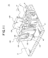
- FIG. 11 is a perspective view showing an attaching structure according to a second embodiment of the present invention.
- FIG. 12 is a sectional view showing a first part composing the attaching object of the attaching structure shown in FIG. 11 attached to the attaching hole of the panel;
- FIG. 13 is a sectional view showing a second part composing the attaching object of the attaching structure shown in FIG. 11 assembled with the first part temporarily locked on the attaching hole of the panel;
- FIG. 14 is a sectional view showing the second part shown in FIG. 13 assembled with the first part, and the first part permanently locked on the attaching hole of the panel;
- FIG. 15 is a perspective view showing an attaching structure according to a third embodiment of the present invention.
- FIG. 16 is a perspective view showing a first part composing the attaching object of the attaching structure shown in FIG. 15 ;
- FIG. 17 is a sectional view showing the first part shown in FIG. 6 attached to the attaching hole of the panel;
- FIG. 18 is a sectional view showing the first part shown in FIG. 7 temporarily locked on the attaching hole of the panel;
- FIG. 19 is a sectional view showing a second part composing the attaching object of the attaching structure shown in FIG. 15 assembled with the first part temporarily locked on the attaching hole of the panel;
- FIG. 20 is a sectional view showing the second part shown in FIG. 19 assembled with the first part, and the first part permanently locked on the attaching hole;
- FIG. 21 is a sectional view showing a conventional attaching structure for attaching a conventional room lighting system to an attaching hole of a roof trim;
- FIG. 22 is a sectional view showing the room lighting system shown in FIG. 21 locked on the attaching hole of the roof trim.
- FIG. 23 is a sectional view for explaining a problem of the conventional attaching structure of the room lighting system shown in FIGS. 21 and 22 .
- FIGS. 1 to 9 An attaching structure 1 A according to a first embodiment of the present invention will be explained with FIGS. 1 to 9 .
- a room lighting system for a vehicle hereunder referred to as lamp unit 5
- the roof trim 2 is made of synthetic resin and composes a roof of a vehicle.
- the roof trim 2 is mounted on an inside of a cabin.
- the lamp unit 5 illuminates the inside of the cabin, and as shown in FIG. 1 , includes a design part 3 as a first part and a function part 4 as a second part.
- the function part 4 includes a light source such as an LED (light emitting diode) or a light bulb in a housing 40 formed in a substantially rectangular shape and made of synthetic resin.
- a translucent window 42 is mounted on a bottom wall 41 a of the housing 40 for guiding the light from the light source to the cabin.
- the translucent window 42 is interposed between a pair of sidewalls 41 b having a pair of locking projections 43 for engaging with later-described locking holes 37 of the design part 3 .
- the locking projections 43 are projected from the sidewalls 41 b in a direction of separating each other.
- the function part 4 is positioned on a rear side of the attaching hole 21 , namely, a ceiling side.
- the function part 4 is assembled with the design part 3 in a direction that the bottom wall 41 a having the translucent window 42 faces downward, namely, faces the cabin.
- a wiring harness 6 is attached for supplying electric power to the light source.
- the design part 3 is made of synthetic resin and as shown in FIGS. 4 to 6 , includes a plate part 31 , a pair of vertically extending parts 30 , and a function part positioning part 35 .
- the plate part 31 forms an outward appearance of the lamp unit 5 .
- the plate part 31 is positioned in front of the attaching hole 21 , namely, the cabin side and covers the attaching hole 21 , while the lamp unit 5 is attached to the attaching hole 21 .
- the vertically extending parts 30 are vertically extended from the plate part 31 , and face each other.
- the vertically extending parts 30 are positioned at the rear side of the attaching hole 21 , namely, the ceiling side.
- the plate part 31 is formed larger than an outer shape of the attaching hole 21 . While the lamp unit 5 is attached to the attaching hole 21 , the plate part 31 is formed in a square shape in a plan view seeing from the cabin. A translucent hole 31 a is formed on the plate part 31 at a position with which the translucent window 42 overlaps while the function part 4 is assembled with the design part 3 . The light emitted through the translucent window 42 is led to the cabin through the hole 31 a.
- the pair of vertically extending parts 30 respectively includes: a frame part 32 vertically extended from the plate part 31 ; a movable piece 33 continued to the frame part 32 ; and a rib 36 continued to the frame part 32 .
- the frame part 32 is formed in a frame shape, and includes a pair of upright parts 11 and a connecting part 12 .
- Each upright part 11 is formed in a bar shape.
- the upright parts 11 are spaced to each other, and vertically extended in a direction perpendicular to the plate part 31 .
- the connecting part 12 is formed in a bar shape, and connects ends of the upright parts 11 at far sides from the plate part 31 .
- the frame part 32 is hardly resiliently deformed throughout before the design part 3 is attached to the attaching hole 21 and after the design part 3 is permanently locked on the attaching hole 21 . While the design part 3 is permanently locked on the attaching hole 21 , the frame part 32 is positioned on an inside of the attaching hole 21 .
- the movable piece 33 is disposed at an inside of the frame part 32 , and continued to the connecting part 12 of the frame part 32 .
- the movable piece 33 includes: a flat part 13 extended toward the plate part 31 ; a clamping part 34 vertically extended from the flat part 13 ; a pair of ribs 34 a vertically extended from the clamping part 34 as slope members; a pair of first guiding walls 33 a; and a pair of second guiding walls 33 b as guiding members.
- the flat part 13 is disposed slidingly so that a gap between both flat parts 13 becomes narrower from the connecting part 12 to the plate part 31 while the movable piece 33 is not pressed. Namely, a pair of flat parts 13 is disposed slidingly against a vertically extending direction of the upright parts 11 of the frame part 32 while the movable piece 33 is not pressed.
- a connecting part 13 a of the flat part 13 connected to the connecting part 12 is formed thinner than the other parts.
- the connecting part 13 a is formed thinner than the other parts away from the connecting part 12 .
- the flat part 13 is allowed to be bent around the connecting part 13 a in a direction of approaching to and removing from the other flat part 13 .
- a locking hole 37 is formed on the center of the flat part 13 .
- the locking hole 37 is to be engaged with the locking projection 43 of the function part 4 for fixing the function part 4 to the design part 3 .
- the function part 4 is positioned between the pair of flat parts 13 .
- the pair of flat parts 13 at the plate part 31 side is pushed to be extended outward, the pair of flat parts 13 is bent around the connecting part 13 a in a direction of separating each other, so that the outer edge of the later-described movable piece 33 , namely, the outer edge of the attaching hole 21 is positioned further outside of the attaching hole 21 .
- the design part 3 is permanently locked on the attaching hole 21 .
- the clamping part 34 is formed in a plate shape, vertically extended from the flat part 13 at a far side of the other flat part 13 , and vertically extended from an end away from the connecting part 13 a. Further, the clamping part 34 is disposed in a direction of facing the plate part 31 . While the design part 3 is temporarily locked on the attaching hole 21 , an outer edge (corresponding to an outer edge in claim) of the clamping part 34 away from the flat part 13 is positioned outside of the attaching hole 21 , and the edge of the attaching hole 21 is interposed between the clamping part 34 and the plate part 31 . Namely, the outer edge of the clamping part 34 constitutes the outer edge of the movable piece 33 and the outer edge of the vertically extending part 30 .
- the outer edge of the movable piece 33 means the most outside portion of the movable piece 33 in a direction of the pair of movable pieces 33 facing each other.
- the outer edge of the vertically extending part 30 means the most outside portion of the vertically extending part 30 in a direction of the pair of vertically extending parts 30 facing each other.
- the pair of ribs 34 a is extended vertically from the clamping part 34 facing the plate part 31 , and respectively extended vertically from both ends of the clamping part 34 along a width direction of the clamping part 34 with a gap.
- the width direction of the clamping part 34 means a direction perpendicular to a direction of the pair of vertically extending part 30 facing each other.
- the pair of ribs 34 a is extended straight from the outer edge of the clamping part 34 toward the flat part 13 . Extending length of the pair of ribs 34 a is decreased from the flat part 13 toward the outer edge. Namely, as shown in FIG.
- the pair of ribs 34 a breaks into an inner edge at the rear side of the attaching hole 21 .
- the inner edge of the attaching hole 21 means an end wall of the roof trim 2 having the attaching hole 21 , perpendicular to a planar direction of the roof trim 2 .
- the pair of first guiding walls 33 a is formed in a triangle plate shape from a plan view, and disposed having a gap between each other.
- the pair of first guiding walls 33 a connects a surface on the flat part 13 away from the other flat part 13 to both ends along the width direction of the clamping part 34 .
- the first guiding wall 33 a includes a slope wall 331 which inclined further outward of the vertically extending part 30 as the slope wall 331 extends from the connecting part 13 a toward the clamping part 34 .
- the slope wall 331 of the first guiding walls 33 a slides on the inner edge of the attaching hole 21 to bend the pair of movable piece 33 in a direction of approaching each other. Further, the first guiding walls 33 a reinforce strength of the clamping part 34 .
- the pair of second guiding walls 33 b vertically extends from the flat part 13 facing the other flat part 13 in a width direction of the clamping part 34 , and having a gap interposed between each other.
- the pair of second guiding walls 33 b is extended from the connecting part 13 a toward the plate part 31 .
- the second guiding wall 33 b includes a slope wall 332 on an end wall of the second guiding wall 33 b away from the flat part 13 , and an abutting wall 333 continued to the slope wall 332 .
- the slope wall 332 is disposed near the connecting part 13 a, and inclined to approach the movable piece 33 as the slope wall 332 extends from the connecting part 13 a toward the plate part 31 .
- the abutting wall 333 is disposed nearer the plate part 31 than the slope wall 332 .
- the abutting wall 333 abuts on the sidewall 41 b of the function part 4 while the function part 4 is assembled with the design part 3 .
- a gap between the abutting walls 333 of the pair of second guiding walls 33 b facing each other is formed smaller than a width between the pair of sidewalls 41 b of the function part 4 .
- the pair of sidewalls 41 b of the function part 4 slides on the pair of slope walls 332 toward the abutting walls 333 .
- the sidewalls 41 b bend the pair of movable piece 33 in a direction of separating each other, and are gradually pushed into between the abutting walls 333 .
- the locking projections 43 are engaged with the locking holes 37 , the function part 4 is fixed between the pair of movable piece 33 .
- the pair of sidewalls 41 b respectively abuts on the abutting walls 333 .
- the rib 36 vertically extends from the upright part 11 of the frame part 32 toward a width direction of the clamping part 34 , and extends along a longitudinal direction of the upright part 11 . An end of the rib 36 in the longitudinal direction is continued to the plate part 31 . While the design part 3 is permanently locked on the attaching hole 21 , the rib 36 breaks into the inner edge of the attaching hole 21 to prevent the design part 3 from rattling against the attaching hole 21 . Further, the rib 36 reinforces strength of the frame part 32 .
- the function part positioning part 35 is vertically extended from the plate part 31 . While the design part 3 is permanently locked on the attaching hole 21 , the function part positioning part 35 is positioned at the rear side of the attaching hole 21 , namely, the ceiling side. Further, a shape of the function part positioning part 35 is along an outer shape of the housing 40 of the function part 4 . When the function part positioning part 35 abuts on the housing 40 , the function part positioning part 35 positions the housing 40 at a predetermined position.
- the design part 3 separated from the function part 4 is pushed up from the cabin toward the ceiling while the vertically extending part 30 is directed to the ceiling, and the pair of vertically extending parts 30 is inserted into the attaching hole 21 . Then, as shown in FIG. 7 , the design part 3 is temporarily locked on the attaching hole 21 .
- the pair of movable piece 33 is bent around the connecting part 13 a in a direction of approaching each other, and the outer edge of the clamping part 34 is positioned inside the attaching hole 21 , so that the pair of vertically extending part 30 is inserted into the attaching hole 21 .
- a state where the outer edge of the clamping part 34 is positioned inside the attaching hole 21 is expressed as that the vertically extending part 30 is positioned at an insertion position.
- the pair of movable piece 33 is moved in a direction of separating each other owing to the resilient restoring force, and the outer edges of the clamping parts 34 are respectively positioned outside the attaching hole 21 .
- the design part 3 is temporarily locked on the attaching hole 21 while the edge of the attaching hole 21 is caught between the clamping part 34 and the plate part 31 .
- the pair of vertically extending part 30 is bent in a direction of approaching each other, and as shown in FIG. 7 , there is a locking margin W 1 between the clamping part 34 and the edge of the attaching hole 21 .
- a state that the locking margin W 1 exists is expressed by that the vertically extending part 30 is positioned at a temporary locking position.
- the function part 4 is inserted into between the pair of vertically extending part 30 which is temporarily locked on the attaching hole 21 .
- the pair of sidewalls 41 b of the function part 4 is guided toward plate part 31 while sliding on the slope walls 332 .
- the function part 4 is inserted and the gap between the abutting walls 333 is pushed to be extended outward, so that the clamping part 34 having the locking margin W 1 is further shifted outward.
- the rib 34 a breaks into the inner edge at the rear side of the attaching hole 21 to prevent the design part 3 from rattling along a direction of the pair of vertically extending parts 30 facing each other, and a thickness direction of the roof trim 2 .
- the function part positioning part 35 and the outer edge of the rib 36 break into the inner edge of the attaching hole 21 to prevent the design part 3 from rattling in a direction perpendicular to the direction of the pair of vertically extending part 30 facing each other.
- a state that the locking margin W 2 exists is expressed by that the vertically extending part 30 is positioned at the permanent locking position.
- the locking margin between the outer edge f the clamping part 34 and the inner edge of the attaching hole 21 is increased from the temporary locking margin W 1 to the permanent locking margin W 2 . Therefore, the pair of vertically extending part 30 is inserted into the attaching hole 21 with low insertion force to be temporarily locked, and owing to the permanent locking state, sufficient holding force of the edge of the attaching hole 21 is secured. Accordingly, the lamp unit 5 is surely prevented from falling out of the attaching hole 21 .
- the vertically extending part 30 is movable from the temporary locking position to the permanent locking position. Therefore, it is unnecessary to provide a temporary locking member and a permanent locking member respectively, and the design part 3 can be downsized. Further, a structure of the design part 3 can be simplified.
- the movable piece 33 can be bent with a little force, and the pair of vertically extending parts 30 can be inserted into the attaching hole 21 with low insertion force. Further, when the function part 4 is inserted into between the pair of movable piece 33 , sliding resistance of the second guiding walls 33 b is reduced, and the function part 4 is inserted with less insertion force.
- the vertically extending part 30 includes the rib 34 a as the sliding part for breaking into the inner edge at the rear side of the attaching hole 21 when the design part 3 is permanently locked on the attaching hole 21 . Therefore, the design part 3 , namely, the lamp unit 5 can be attached to the attaching hole 21 without rattle.
- the first guiding wall 33 a is provided, when the vertically extending part 30 is inserted into the attaching hole 21 , the design part 3 is only pushed toward the ceiling. Then, the pair of movable piece 33 is bent in a direction of approaching each other, and then returned in a direction of separating each other to be the temporary locking position. Further, because the slope wall 332 of the second guiding wall 33 b is provided, only pushing the function part 4 vertically makes the function part 4 assembled with the design part 3 easily.
- the lamp unit 5 can be attached to the attaching hole 21 with a straight and simple operation. Therefore, assembling workability is good, and the attaching operation can be automated.
- the vertically extending part 30 includes the frame part 32 which is hardly resiliently deformed, solidity of the design part 3 can be increased. Further, a positioning to inserting the vertically extending part 30 into the attaching hole 21 can be accurate. When the frame part 32 is formed in agreement with a size of the attaching hole 21 , it is hard to rattle between the frame part 32 and the attaching hole 21 .
- an attaching structure 1 A′ which is a modified example of the attaching structure 1 A will be explained with reference to FIG. 10 .
- the vertically extending part 30 of the attaching structure 1 A further includes ribs 50 , 51 , 52 .
- the rib 50 connects a pair of first guiding walls 33 a to reinforce strength of the first guiding walls 33 a.
- the rib 51 is formed crossing the center of the rib 50 to reinforce strength of the first guiding walls 33 a.
- the rib 52 is formed in the center of the clamping part 34 in the width direction and extended from an outer edge of the clamping part 34 toward an end of the flat part 13 to reinforce strength of the clamping part 34 .
- the design part 3 ′ reinforced by the ribs 50 , 51 , 52 has better dignity and better endurance than the design part 3 of the attaching structure 1 A.
- a room lighting system for a vehicle (hereunder referred to as lamp unit 5 ′′) as the attaching object is attached to the attaching hole 21 formed on the roof trim 2 of the vehicle as the panel.
- the lamp unit 5 ′′ is identical to those in the attaching structures 1 A, 1 A′ except a design part 103 .
- the design part 103 is made of resilient synthetic resin, and includes: the plate part 31 composing the outside appearance; and a pair of vertically extending parts 130 facing each other, and vertically extended from the plate part 31 to be positioned at the rear side of the attaching hole 21 , namely, the ceiling side.
- Each vertically extending part 130 includes: a connecting part 132 vertically extended from the plate part 31 ; a main part 133 continued to the connecting part 132 at a far side from the plate part 31 ; a guiding part 134 continued to the main part 133 at a far side from the plate part 31 ; and a rib 135 as a slope part.
- a thickness of the connecting part 132 is formed thinner than those of the plate part 31 and the main part 133 . Therefore, the vertically extending part 130 is to be bent around the connecting part 132 in directions of approaching and separating from the other vertically extending part 130 .
- the main part 133 includes: a first main part 133 a continued to the connecting part 132 , and extended in a direction of separating from the other vertically extending part 130 ; and a second main part 133 b formed in a plate shape, continued to an end of the first main part 133 a at a far side from the connecting part 132 , and extended in a direction of crossing the first main part 133 a.
- a locking hole 137 configured to be engaged with the locking projection 43 of the function part 4 and fix the function part 4 onto the design part 3 is formed on the second main part 133 b.
- the second main part 133 b is so inclined that a gap between the pair of second main parts 133 b is reduced as the second main part 133 b extends from the first main part 133 a to the guiding part 134 , while the vertically extending parts 130 are not pushed and the design part 103 is temporarily locked on the attaching hole 21 .
- the gap between the second main parts 133 b is formed smaller than a gap between the pair of sidewalls 41 b of the function part 4 .
- the pair of vertically extending parts 130 of the main part 133 is bent around the connecting part 132 in a direction of separating each other to position the function part 4 between the pair of main parts 133 .
- the bottom wall 41 a having the translucent window 42 of the function part 4 abuts on the first main part 133 a
- the sidewall 41 b having the locking projections 43 abuts on the second main part 133 b.
- the guiding part 134 is formed in a plate shape, and inclined against the second main part 133 b. Also, the guiding part 134 is so inclined to be disposed further away from the other vertically extending part 130 as the guiding part 134 is disposed further away from the second main part 133 b. A gap between the pair of guiding parts 134 at the far ends from the main parts 133 is larger than a gap between the pair of sidewalls 41 b of the function part 4 while the design part 103 is temporarily locked on the attaching hole 21 (see FIG. 13 ).
- the pair of sidewalls 41 b of the function part 4 slides on surfaces facing each other of the pair of guiding part 134 toward the second main part 133 b.
- the pair of sidewalls 41 b approaches the second main part 133 b, while bending the pair of vertically extending parts 130 in a direction of separating each other, the pair of sidewalls 41 b is gradually pushed into between the second main parts 133 b.
- the pair of sidewalls 41 b is fixed between the pair of second main part 133 b. Under this condition, the pair of sidewalls 41 b respectively abuts on the second main parts 133 b.
- ribs 136 reinforce strength of the guiding part 134 .
- the rib 135 is extended vertically from a surface facing the plate part 31 of the first main part 133 a.
- the rib 135 is extended straight from an outer edge of the first main part 133 a toward the connecting part 132 .
- the rib 135 is so inclined that as the an edge of the rib 135 away from the first main part 133 a is removed from the connecting part 132 , namely, extended from the inside to the outside of the attaching hole 21 , the rib 135 is removed from the plate part 31 .
- the design part 103 is permanently locked from a state that the design part 103 is temporarily locked on the attaching hole 21 (see FIG. 13 )
- the rib 135 breaks into the inner edge of the attaching hole 21 at the rear side thereof to prevent the design part 103 from rattling against the attaching hole 21 .
- the first main part 133 a as an outer edge of the vertically extending part 130 is positioned at an inside of the attaching hole 21 , namely, at the insertion position to be inserted into the attaching hole 21 .
- the vertically extending parts 130 is moved around the connecting part 132 in a direction of separating each other owing to the resilient restoring force, and the first main part 133 a is positioned at an outside of the attaching hole 21 , namely, at the temporary locking position, and then, as shown in FIG. 13 , the design part 103 is temporarily locked on the attaching hole 21 .
- the function part 4 pushes the pair of vertically extending parts 130 .
- the pair of vertically extending parts 130 is bent around the connecting part 132 in a direction of separating each other, and the first main part 133 a is positioned at the further outside of the attaching hole 21 , namely, at the permanent locking position, so that the design part 103 is permanently locked on the attaching hole 21 as shown in FIG. 14 .
- the edge of the attaching hole 21 is caught between the first main part 133 a and the plate part 31 .
- the pair of vertically extending parts 130 of the design part 103 removed from the function part 4 is bent in a direction of approaching each other, so that the pair of vertically extending parts 130 is shifted to the insertion position where the first main part 133 a is positioned at an inside of the attaching hole 21 . Further, from this condition, the design part 103 is pushed from the cabin side toward the ceiling side, so that the design part 103 is temporarily locked on the attaching hole 21 as shown in FIG. 13 . In the temporarily locked condition, the pair of vertically extending parts 130 is bent in a direction of approaching each other, and there is a locking margin W 3 between the first main part 133 a and the edge of the attaching hole 21 .
- the function part 4 having the wiring harness 6 is inserted into between the pair of vertically extending parts 130 of the design part 103 temporarily locked on the attaching hole 21 .
- the pair of sidewalls 41 b of the function part 4 slides on the guiding part 134 to be guided toward the second main part 133 b.
- the function part 4 is inserted to push the gap between the second main parts 133 b, the first main part 133 a is moved to the further outside of the attaching hole 21 .
- the function part 4 is further pushed into between the second main parts 133 b, as shown in FIG. 14 , the locking projection 43 of the function part 4 is engaged with the locking hole 137 of the movable piece 33 , so that the function part 4 is assembled with the design part 103 .
- the second main part 133 b resiliently contacts the sidewalls 41 b of the function part 4 .
- the first main part 133 a is positioned at a position where the locking margin with the edge of the attaching hole 21 becomes W 4 , and the design part 103 , namely, the lamp unit 5 ′′ is permanently locked on the attaching hole 21 .
- the rib 135 breaks into the inner edge of the attaching hole 21 at the rear side to prevent the design part 103 from rattling in the direction of the pair of vertically extending parts 130 facing each other.
- the locking margin between the first main part 133 a and the edge of the attaching hole 21 is increased from W 3 at the temporary locking to W 4 at the permanent locking. Therefore, the pair of vertically extending parts 130 can be inserted into the attaching hole 21 to be temporarily locked with low insertion force. Further, owing to the permanent locking after the temporary locking, a sufficient holding force for holding the edge of the attaching hole 21 is secured.
- the design part 103 according to the attaching structure 1 B of this embodiment is simpler than the design parts 3 , 3 ′ of the attaching structures 1 A, 1 A′, the cost of the lamp unit 5 ′′ is lower than those of the lamp units 5 , 5 ′.
- the attaching structure 1 C is a structure for attaching a room lighting system (hereafter referred to as a lamp unit 5 ′′′) as the attaching object to the attaching hole 21 formed on the roof trim 2 of a vehicle as the panel.
- the lamp unit 5 ′′′ is the same as those in the attaching structure 1 A, 1 A′, 1 B except the design part 303 , namely, the function part 4 .
- the design part 303 is made of resilient synthetic resin. As shown in FIG. 16 , the design part 303 includes: the plate part 31 composing the outside appearance of the lamp unit 5 ′′′; a pair of vertically extending parts 330 facing each other, and vertically extended from the plate part 31 to be positioned at the rear side of the attaching hole 21 , namely, the ceiling side; and the function part positioning part 35 .
- Each vertically extending part 330 includes: a main part 8 vertically extended from the plate part 31 ; a clamping part 334 vertically extended from the main part 8 as a slope part; and a pair of guiding parts 333 a.
- the main part 8 is formed in a plate shape.
- the main part 8 is formed in a direction to be parallel with the other main part 8 facing each other while the vertically extending parts 330 are not pushed. Further, while the vertically extending parts 330 are not pressed, and the design part 303 is temporarily locked on the attaching hole 21 , a gap between the main parts 8 facing each other is smaller than a width between the pair of sidewalls 41 b of the function part 4 .
- a connecting part 7 of the main part 8 connected to the plate part 31 namely, an end of the main part 8 disposed at the plate part 31 side is thinner than the other parts of the main part 8 .
- the connecting part 7 is thinner than the parts of the main part 8 at a far side from the connecting part 7 .
- the main part 8 is so formed as to bend around the connecting part 7 in directions of approaching and separating from the other main part 8 .
- the outer edges of the later-described clamping parts 334 namely, the outer edges of the vertically extending parts 330 are positioned outside the attaching hole 21 , and as shown in FIG. 18 , the design part 303 is temporarily locked on the attaching hole 21 .
- a locking hole 337 for fixing the function part 4 to the design part 303 by engaging with the locking projection 43 of the function part 4 is formed on the center of the main part 8 .
- the function part 4 is positioned between the pair of main parts 8 .
- the pair of main parts 8 is pushed to be bent around the connecting part 7 in a direction of separating each other.
- the plate part 31 connected to the main parts 8 is pushed toward the rear side of the attaching hole 21 .
- the plate part 31 abuts on a surface of the roof trim 2 at the cabin side without any gap.
- the clamping part 334 is formed in a plate shape, vertically extended from the main part 8 at a far side of the other main part 8 , and vertically extended from an end near the connecting part 7 . Further, the clamping part 334 is disposed in a direction of facing the plate part 31 . While the design part 303 is permanently locked on the attaching hole 21 , the clamping part 334 is inclined to remove further away from the plate part 31 as the clamping part 334 is removed further away from the main part 8 .
- the outer edge of the clamping part 334 constitutes an outer edge of the vertically extending part 330 .
- the outer edge of the vertically extending part 330 means the most outside portion of the vertically extending part 330 in a direction of the pair of vertically extending parts 330 facing each other.
- the outer edge of the clamping part 334 away from the main part 8 is positioned further outside the attaching hole 21 than that at the temporary locking state.
- the edge of the attaching hole 21 is caught between the outer edge of the clamping part 334 and the plate part 31 .
- the function part 4 inserted into between the pair of main parts 8 bends the main parts 8 in a direction of separating each other, namely, outside the attaching hole 21 , so that the clamping part 334 breaks into the inner edge of the attaching hole 21 at the rear side.
- the pair of guiding parts 333 a is formed in a triangular shape in a plan view, and disposed with a gap to each other.
- the pair of guiding parts 333 a connects a surface of the main part 8 away from the other main part 8 to both edges of the clamping part 334 along a width direction thereof.
- the guiding part 333 a includes the slope wall 331 which is inclined in a direction of extending from the outer edge of the clamping part 334 to the main part 8 as the guiding part 333 a removes from the connecting part 7 along the extending direction of the main part 8 while the vertically extending parts 330 are not pushed.
- the slope walls 331 of the guiding parts 333 a slide on the inner edge of the attaching hole 21 to bend the pair of vertically extending parts 330 in a direction of approaching each other. Further, the guiding parts 333 a reinforce strength of the clamping parts 334 .
- the design part 303 separated from the function part 4 is pushed up from the cabin side toward the ceiling side while the abutting wall 333 faces the ceiling. Then, the pair of vertically extending parts 330 is inserted into the attaching hole 21 , and as shown in FIG. 18 , the design part 3 is temporarily locked on the attaching hole 21 .
- the pair of vertically extending parts 330 is moved in a direction of separating each other owing to the resilient restoring force, and the outer edges of the clamping parts 334 are respectively positioned outside the attaching hole 21 .
- the design part 303 is temporarily locked on the attaching hole 21 while the edge of the attaching hole 21 is caught between the clamping part 334 and the plate part 31 .
- the pair of vertically extending parts 330 is bent in a direction of approaching each other, and the clamping part 334 is so positioned that the locking margin to the edge of the attaching hole 21 is W 5 .
- a state that the clamping part 334 is positioned at the position where the locking margin to the edge of the attaching hole 21 is W 5 is expressed by that the vertically extending part 330 is positioned at the temporary locking position.
- the function part 4 is inserted into between the pair of main parts 8 of the design part 303 which is temporarily locked on the attaching hole 21 .
- the clamping part 334 is shifted further outside the attaching hole 21 .
- the clamping part 334 breaks into the inner edge of the attaching hole 21 at the rear side to prevent the design part 303 from rattling in a direction of the pair of vertically extending parts 330 facing each other.
- a state that the clamping part 334 is positioned at the position where the locking margin to the edge of the attaching hole 21 is W 6 is expressed by that the vertically extending parts 330 are positioned at the permanent locking position.
- the function part 4 when the function part 4 is assembled with the design part 303 , the locking margin between the clamping part 334 and the edge of the attaching hole 21 is increased from W 5 at the temporary locking state to W 6 at the permanent locking state. Therefore, the pair of vertically extending parts 330 can be inserted into the attaching hole 21 with low insertion force at the temporary locking state, and sufficient holding force to the edge of the attaching hole 21 is secured owing to the permanent locking state. Accordingly, the lamp unit 5 ′′′ is surely prevented from falling out of the attaching hole 21 .
- the main parts 8 does not bend in a direction of approaching each other. Therefore, the locking margin to the edge of the attaching hole 21 does not change. Therefore, the lamp unit 5 ′′′ is further surely prevented from falling out of the attaching hole 21 , and the function part 4 is prevented from falling out of the design part 303 .
- the plate part 31 connected to the main parts 8 is pulled toward the rear side of the attaching hole 21 . Therefore, the plate part 31 abuts on a surface of the roof trim 2 at the cabin side without any gap.
- the vertically extending part 330 includes the clamping part 334 as the slope breaking into the inner edge of the attaching hole 21 at the rear side while the design part 303 is permanently locked on the attaching hole 21 , the design part 303 , namely, the lamp unit 5 ′′′ can be attached to the attaching hole 21 without rattle.
- the slope part may be the rib 34 a described in the first embodiment, or may be the clamping part 334 described in the second embodiment.
Applications Claiming Priority (4)
| Application Number | Priority Date | Filing Date | Title |
|---|---|---|---|
| JP2006192637 | 2006-07-13 | ||
| JP2006-192637 | 2006-07-13 | ||
| JP2007141922A JP4908315B2 (ja) | 2006-07-13 | 2007-05-29 | 取付構造 |
| JP2007-141922 | 2007-05-29 |
Publications (2)
| Publication Number | Publication Date |
|---|---|
| US20080011930A1 US20080011930A1 (en) | 2008-01-17 |
| US7562857B2 true US7562857B2 (en) | 2009-07-21 |
Family
ID=38948302
Family Applications (1)
| Application Number | Title | Priority Date | Filing Date |
|---|---|---|---|
| US11/826,277 Expired - Fee Related US7562857B2 (en) | 2006-07-13 | 2007-07-13 | Attaching structure |
Country Status (3)
| Country | Link |
|---|---|
| US (1) | US7562857B2 (de) |
| JP (1) | JP4908315B2 (de) |
| DE (1) | DE102007032554B4 (de) |
Cited By (4)
| Publication number | Priority date | Publication date | Assignee | Title |
|---|---|---|---|---|
| US20130031714A1 (en) * | 2011-08-03 | 2013-02-07 | Custom Molded Products, Inc. | Retention clip |
| US20150328951A1 (en) * | 2014-05-14 | 2015-11-19 | Denso International America, Inc. | Detachable holder |
| US20170335870A1 (en) * | 2016-05-20 | 2017-11-23 | Yazaki North America, Inc. | Tuneless cantilever system |
| US11021868B2 (en) * | 2017-03-21 | 2021-06-01 | Joeun-Deco Co., Ltd | Finishing panel fixing device |
Families Citing this family (18)
| Publication number | Priority date | Publication date | Assignee | Title |
|---|---|---|---|---|
| JP4908315B2 (ja) * | 2006-07-13 | 2012-04-04 | 矢崎総業株式会社 | 取付構造 |
| US7735793B2 (en) * | 2006-09-11 | 2010-06-15 | Robert Whitt | Quick-release mounting bracket for a hand truck |
| JP5524477B2 (ja) * | 2008-12-11 | 2014-06-18 | 矢崎総業株式会社 | ランプ装置の取付構造 |
| JP5524478B2 (ja) * | 2008-12-19 | 2014-06-18 | 矢崎総業株式会社 | ランプ装置の取付構造 |
| JP5373425B2 (ja) * | 2009-02-18 | 2013-12-18 | 矢崎総業株式会社 | 室内照明装置 |
| US20100213337A1 (en) * | 2009-02-23 | 2010-08-26 | Fergin Earl G | Mounting assembly |
| EP2230733B1 (de) * | 2009-03-19 | 2015-12-16 | Schlemmer Gmbh | Einbauadapter |
| US9812684B2 (en) | 2010-11-09 | 2017-11-07 | GM Global Technology Operations LLC | Using elastic averaging for alignment of battery stack, fuel cell stack, or other vehicle assembly |
| WO2013132987A1 (ja) * | 2012-03-08 | 2013-09-12 | テイ・エス テック株式会社 | 照明装置の取付構造 |
| JP5639691B1 (ja) | 2013-07-08 | 2014-12-10 | 株式会社ホンダアクセス | 板状部材に対する部品の取付構造 |
| JP5666656B2 (ja) * | 2013-07-08 | 2015-02-12 | 株式会社ホンダアクセス | 板状部材に対する部品の取付構造 |
| US9669774B2 (en) | 2013-10-11 | 2017-06-06 | GM Global Technology Operations LLC | Reconfigurable vehicle interior assembly |
| US9599279B2 (en) * | 2013-12-19 | 2017-03-21 | GM Global Technology Operations LLC | Elastically deformable module installation assembly |
| US9657807B2 (en) | 2014-04-23 | 2017-05-23 | GM Global Technology Operations LLC | System for elastically averaging assembly of components |
| US9758110B2 (en) | 2015-01-12 | 2017-09-12 | GM Global Technology Operations LLC | Coupling system |
| DE102017003420A1 (de) | 2017-04-07 | 2018-10-11 | Ykk Corporation | Verbindungsvorrichtung, clippatrize für eine solche verbindungs- vorrichtung, sitzbezug mit einer clippatrize einer solchen verbindungsvorrichtung und sitz mit einer solchen verbindungsvorrichtung |
| WO2020209834A1 (en) * | 2019-04-08 | 2020-10-15 | Hewlett-Packard Development Company, L.P. | Devices for retaining articles |
| JP7004922B2 (ja) * | 2019-12-04 | 2022-02-07 | テイ・エス テック株式会社 | 照明装置の取付構造及び車両用ドア |
Citations (29)
| Publication number | Priority date | Publication date | Assignee | Title |
|---|---|---|---|---|
| US2889124A (en) * | 1953-04-29 | 1959-06-02 | Sylvania Electric Prod | Means for mounting plastic parts |
| US3213189A (en) * | 1963-04-02 | 1965-10-19 | United Carr Inc | Fastener cap |
| US4139755A (en) * | 1976-07-06 | 1979-02-13 | Cutler-Hammer, Inc. | Snap-in bushing electric switch including a frame with integral back-up elements having panel-engaging ramped riser bars |
| US4406936A (en) * | 1980-10-11 | 1983-09-27 | Nihon Kaiheiki Kogyo Kabushiki Kaisha | Mounting frame equipped with decorative plate for mounting switch or the like |
| US4602760A (en) * | 1983-11-28 | 1986-07-29 | Tiefenbach Karolyn L | Fuel line bundle clamp |
| US4702711A (en) * | 1985-04-24 | 1987-10-27 | General Electric Company | Snap-action bayonet-type fastening device for control and/or signalling units |
| US5056853A (en) * | 1989-08-16 | 1991-10-15 | Prince Corporation | Snap-in visor mount |
| US5217190A (en) * | 1990-08-10 | 1993-06-08 | The Siemon Company | Panel yoke |
| US5343006A (en) * | 1993-03-24 | 1994-08-30 | Thrustmaster, Inc. | Panel mount switch assembly |
| US5475577A (en) * | 1992-07-07 | 1995-12-12 | Donnelly Corporation | Accessory attachment plate for vehicle panels |
| US5662375A (en) * | 1994-12-02 | 1997-09-02 | Donnelly Corporation | Mounting clip |
| US5718549A (en) * | 1995-04-17 | 1998-02-17 | Piolax, Inc. | Releasable two-part fixing clip |
| US5752853A (en) * | 1995-12-13 | 1998-05-19 | United Technologies Automotive Systems, Inc. | Snap-in visor mount and electrical connectors for visor mounts |
| US6007136A (en) * | 1998-10-02 | 1999-12-28 | Fourslides Inc. | Modular visor attachment fastener |
| US6021986A (en) * | 1997-07-24 | 2000-02-08 | Lear Automotive Dearborn, Inc. | Snap-in mount |
| US6158802A (en) * | 1997-11-13 | 2000-12-12 | Honda Giken Kogyo Kabushiki Kaisha | Switch mounting structure in a vehicle |
| US20020005464A1 (en) * | 2000-07-04 | 2002-01-17 | Hideya Miura | Plate member mounting structure |
| US6406087B2 (en) * | 1999-12-24 | 2002-06-18 | Yazaki Corporation | Bracket for attaching interior equipment |
| US6511029B2 (en) * | 2000-03-15 | 2003-01-28 | Yazaki Corporation | Bracket for mounting an accessory on vehicle body |
| US6726165B2 (en) * | 2001-05-11 | 2004-04-27 | Yazaki Corporation | Bracket connecting structure |
| US6799743B2 (en) * | 2000-03-23 | 2004-10-05 | Yazaki Corporation | Bracket for mounting auxiliary machinery to vehicle body |
| US6817583B2 (en) * | 2002-09-18 | 2004-11-16 | Lear Corporation | Interior trim attachment apparatus and method for a vehicle |
| JP2005075219A (ja) | 2003-09-02 | 2005-03-24 | Yazaki Corp | 室内照明灯 |
| US20080011930A1 (en) * | 2006-07-13 | 2008-01-17 | Yazaki Corporation | Attaching structure |
| US20080087744A1 (en) * | 2006-10-11 | 2008-04-17 | Koito Manufacturing Co., Ltd. | Structure For Attaching A Vehicle Lamp Cleaning Device |
| US20080093521A1 (en) * | 2006-10-23 | 2008-04-24 | Sumitomo Wiring Systems, Ltd. | Clamp for use in wire harness |
| US20080184802A1 (en) * | 2007-02-05 | 2008-08-07 | Denso Corporation | Mount structure for sensor device |
| US20080224006A1 (en) * | 2007-03-12 | 2008-09-18 | Dana Innovations | Mounting System For Flush Assembly in Walls and Ceilings in Walls And Ceilings |
| US20090052194A1 (en) * | 2007-08-24 | 2009-02-26 | Jowid Albert M | Light Fixture Assembly and Method |
Family Cites Families (6)
| Publication number | Priority date | Publication date | Assignee | Title |
|---|---|---|---|---|
| JPS5767327A (en) * | 1980-10-15 | 1982-04-23 | Nissin Electric Co Ltd | Error testing device |
| JPH065469B2 (ja) * | 1984-08-30 | 1994-01-19 | 松下電器産業株式会社 | 表示装置 |
| JPS62105887A (ja) * | 1985-11-01 | 1987-05-16 | 株式会社日立製作所 | 伸縮スプレツダ |
| AU626479B2 (en) * | 1989-12-12 | 1992-07-30 | W.A. Deutsher Pty Ltd | Two part fastener |
| JP4303459B2 (ja) * | 2002-10-04 | 2009-07-29 | ダイハツ工業株式会社 | 照明ランプ |
| JP2007141922A (ja) * | 2005-11-15 | 2007-06-07 | Pre-Tech Co Ltd | 基板洗浄装置及びそれを用いた基板洗浄方法 |
-
2007
- 2007-05-29 JP JP2007141922A patent/JP4908315B2/ja not_active Expired - Fee Related
- 2007-07-12 DE DE102007032554A patent/DE102007032554B4/de not_active Expired - Fee Related
- 2007-07-13 US US11/826,277 patent/US7562857B2/en not_active Expired - Fee Related
Patent Citations (30)
| Publication number | Priority date | Publication date | Assignee | Title |
|---|---|---|---|---|
| US2889124A (en) * | 1953-04-29 | 1959-06-02 | Sylvania Electric Prod | Means for mounting plastic parts |
| US3213189A (en) * | 1963-04-02 | 1965-10-19 | United Carr Inc | Fastener cap |
| US4139755A (en) * | 1976-07-06 | 1979-02-13 | Cutler-Hammer, Inc. | Snap-in bushing electric switch including a frame with integral back-up elements having panel-engaging ramped riser bars |
| US4406936A (en) * | 1980-10-11 | 1983-09-27 | Nihon Kaiheiki Kogyo Kabushiki Kaisha | Mounting frame equipped with decorative plate for mounting switch or the like |
| US4602760A (en) * | 1983-11-28 | 1986-07-29 | Tiefenbach Karolyn L | Fuel line bundle clamp |
| US4702711A (en) * | 1985-04-24 | 1987-10-27 | General Electric Company | Snap-action bayonet-type fastening device for control and/or signalling units |
| US5056853A (en) * | 1989-08-16 | 1991-10-15 | Prince Corporation | Snap-in visor mount |
| US5217190A (en) * | 1990-08-10 | 1993-06-08 | The Siemon Company | Panel yoke |
| US5475577A (en) * | 1992-07-07 | 1995-12-12 | Donnelly Corporation | Accessory attachment plate for vehicle panels |
| US5343006A (en) * | 1993-03-24 | 1994-08-30 | Thrustmaster, Inc. | Panel mount switch assembly |
| US5662375A (en) * | 1994-12-02 | 1997-09-02 | Donnelly Corporation | Mounting clip |
| US5718549A (en) * | 1995-04-17 | 1998-02-17 | Piolax, Inc. | Releasable two-part fixing clip |
| US5752853A (en) * | 1995-12-13 | 1998-05-19 | United Technologies Automotive Systems, Inc. | Snap-in visor mount and electrical connectors for visor mounts |
| US6021986A (en) * | 1997-07-24 | 2000-02-08 | Lear Automotive Dearborn, Inc. | Snap-in mount |
| US6158802A (en) * | 1997-11-13 | 2000-12-12 | Honda Giken Kogyo Kabushiki Kaisha | Switch mounting structure in a vehicle |
| US6007136A (en) * | 1998-10-02 | 1999-12-28 | Fourslides Inc. | Modular visor attachment fastener |
| US6406087B2 (en) * | 1999-12-24 | 2002-06-18 | Yazaki Corporation | Bracket for attaching interior equipment |
| US6511029B2 (en) * | 2000-03-15 | 2003-01-28 | Yazaki Corporation | Bracket for mounting an accessory on vehicle body |
| US6799743B2 (en) * | 2000-03-23 | 2004-10-05 | Yazaki Corporation | Bracket for mounting auxiliary machinery to vehicle body |
| US20020005464A1 (en) * | 2000-07-04 | 2002-01-17 | Hideya Miura | Plate member mounting structure |
| US6481682B2 (en) * | 2000-07-04 | 2002-11-19 | Nifco Inc. | Plate member mounting structure |
| US6726165B2 (en) * | 2001-05-11 | 2004-04-27 | Yazaki Corporation | Bracket connecting structure |
| US6817583B2 (en) * | 2002-09-18 | 2004-11-16 | Lear Corporation | Interior trim attachment apparatus and method for a vehicle |
| JP2005075219A (ja) | 2003-09-02 | 2005-03-24 | Yazaki Corp | 室内照明灯 |
| US20080011930A1 (en) * | 2006-07-13 | 2008-01-17 | Yazaki Corporation | Attaching structure |
| US20080087744A1 (en) * | 2006-10-11 | 2008-04-17 | Koito Manufacturing Co., Ltd. | Structure For Attaching A Vehicle Lamp Cleaning Device |
| US20080093521A1 (en) * | 2006-10-23 | 2008-04-24 | Sumitomo Wiring Systems, Ltd. | Clamp for use in wire harness |
| US20080184802A1 (en) * | 2007-02-05 | 2008-08-07 | Denso Corporation | Mount structure for sensor device |
| US20080224006A1 (en) * | 2007-03-12 | 2008-09-18 | Dana Innovations | Mounting System For Flush Assembly in Walls and Ceilings in Walls And Ceilings |
| US20090052194A1 (en) * | 2007-08-24 | 2009-02-26 | Jowid Albert M | Light Fixture Assembly and Method |
Cited By (6)
| Publication number | Priority date | Publication date | Assignee | Title |
|---|---|---|---|---|
| US20130031714A1 (en) * | 2011-08-03 | 2013-02-07 | Custom Molded Products, Inc. | Retention clip |
| US20150328951A1 (en) * | 2014-05-14 | 2015-11-19 | Denso International America, Inc. | Detachable holder |
| US9541110B2 (en) * | 2014-05-14 | 2017-01-10 | Denso International America, Inc. | Detachable holder |
| US20170335870A1 (en) * | 2016-05-20 | 2017-11-23 | Yazaki North America, Inc. | Tuneless cantilever system |
| US10865819B2 (en) * | 2016-05-20 | 2020-12-15 | Yazaki North America, Inc. | Tuneless cantilever system |
| US11021868B2 (en) * | 2017-03-21 | 2021-06-01 | Joeun-Deco Co., Ltd | Finishing panel fixing device |
Also Published As
| Publication number | Publication date |
|---|---|
| US20080011930A1 (en) | 2008-01-17 |
| DE102007032554B4 (de) | 2012-12-06 |
| DE102007032554A1 (de) | 2008-02-21 |
| JP4908315B2 (ja) | 2012-04-04 |
| JP2008037413A (ja) | 2008-02-21 |
Similar Documents
| Publication | Publication Date | Title |
|---|---|---|
| US7562857B2 (en) | Attaching structure | |
| US7640635B2 (en) | Fixing clip for interior part of vehicle | |
| JP5130118B2 (ja) | 車載用室内照明装置 | |
| JP5721446B2 (ja) | 室内ランプの固定構造 | |
| US20150102616A1 (en) | Bumper attachment structure | |
| US20190016261A1 (en) | Attachment structure for lighting device | |
| JP4338581B2 (ja) | 車両用室内照明灯 | |
| US20020126495A1 (en) | Room lamp for vehicle | |
| JPH0997653A (ja) | 可動コネクタ用クリップ | |
| JP2009113563A (ja) | 衝撃吸収アセンブリおよびその取付方法 | |
| JP6193002B2 (ja) | 照明装置の取付構造 | |
| JPH09270201A (ja) | 車輌用灯具 | |
| JP7368758B2 (ja) | 照明装置の取付構造 | |
| US20130058119A1 (en) | Vehicle room lamp | |
| KR200489371Y1 (ko) | 지지부를 이용한 차량용 전장 박스의 결합 구조 | |
| JP2017098057A (ja) | 車両用灯具のコネクタ取付構造 | |
| JP6627922B2 (ja) | 照明装置の取付構造及び車両用ドア | |
| JP4570665B2 (ja) | 照明装置の取付構造 | |
| JP6363775B2 (ja) | 照明装置の取付構造 | |
| CN208546921U (zh) | 发光组件和车辆 | |
| JP2006044589A (ja) | 内装部品の結合構造 | |
| JP5745998B2 (ja) | 車両用灯具の取付構造 | |
| KR102319853B1 (ko) | 램프 유닛, 및 램프 유닛을 구비한 차량용 도어 | |
| JP5438639B2 (ja) | 樹脂部材の取付構造 | |
| JP5222531B2 (ja) | 車載用室内照明装置 |
Legal Events
| Date | Code | Title | Description |
|---|---|---|---|
| AS | Assignment |
Owner name: YAZAKI CORPORATION, JAPAN Free format text: ASSIGNMENT OF ASSIGNORS INTEREST;ASSIGNORS:NAGAI, KENTARO;MIZUSHIMA, TAKAYUKI;SAWAYANAGI, MASAHIRO;AND OTHERS;REEL/FRAME:019596/0265 Effective date: 20070629 |
|
| STCF | Information on status: patent grant |
Free format text: PATENTED CASE |
|
| FEPP | Fee payment procedure |
Free format text: PAYOR NUMBER ASSIGNED (ORIGINAL EVENT CODE: ASPN); ENTITY STATUS OF PATENT OWNER: LARGE ENTITY |
|
| FPAY | Fee payment |
Year of fee payment: 4 |
|
| FPAY | Fee payment |
Year of fee payment: 8 |
|
| FEPP | Fee payment procedure |
Free format text: MAINTENANCE FEE REMINDER MAILED (ORIGINAL EVENT CODE: REM.); ENTITY STATUS OF PATENT OWNER: LARGE ENTITY |
|
| LAPS | Lapse for failure to pay maintenance fees |
Free format text: PATENT EXPIRED FOR FAILURE TO PAY MAINTENANCE FEES (ORIGINAL EVENT CODE: EXP.); ENTITY STATUS OF PATENT OWNER: LARGE ENTITY |
|
| STCH | Information on status: patent discontinuation |
Free format text: PATENT EXPIRED DUE TO NONPAYMENT OF MAINTENANCE FEES UNDER 37 CFR 1.362 |
|
| FP | Lapsed due to failure to pay maintenance fee |
Effective date: 20210721 |