US5718549A - Releasable two-part fixing clip - Google Patents
Releasable two-part fixing clip Download PDFInfo
- Publication number
- US5718549A US5718549A US08/633,552 US63355296A US5718549A US 5718549 A US5718549 A US 5718549A US 63355296 A US63355296 A US 63355296A US 5718549 A US5718549 A US 5718549A
- Authority
- US
- United States
- Prior art keywords
- engaging projections
- female member
- fixing clip
- pair
- shank
- Prior art date
- Legal status (The legal status is an assumption and is not a legal conclusion. Google has not performed a legal analysis and makes no representation as to the accuracy of the status listed.)
- Expired - Fee Related
Links
- 238000003780 insertion Methods 0.000 claims abstract description 7
- 230000037431 insertion Effects 0.000 claims abstract description 7
- 238000004078 waterproofing Methods 0.000 description 5
- 230000015572 biosynthetic process Effects 0.000 description 2
- 238000000926 separation method Methods 0.000 description 2
- 229920003002 synthetic resin Polymers 0.000 description 2
- 239000000057 synthetic resin Substances 0.000 description 2
- 238000004519 manufacturing process Methods 0.000 description 1
- 238000009751 slip forming Methods 0.000 description 1
Images


Classifications
-
- F—MECHANICAL ENGINEERING; LIGHTING; HEATING; WEAPONS; BLASTING
- F16—ENGINEERING ELEMENTS AND UNITS; GENERAL MEASURES FOR PRODUCING AND MAINTAINING EFFECTIVE FUNCTIONING OF MACHINES OR INSTALLATIONS; THERMAL INSULATION IN GENERAL
- F16B—DEVICES FOR FASTENING OR SECURING CONSTRUCTIONAL ELEMENTS OR MACHINE PARTS TOGETHER, e.g. NAILS, BOLTS, CIRCLIPS, CLAMPS, CLIPS OR WEDGES; JOINTS OR JOINTING
- F16B5/00—Joining sheets or plates, e.g. panels, to one another or to strips or bars parallel to them
- F16B5/06—Joining sheets or plates, e.g. panels, to one another or to strips or bars parallel to them by means of clamps or clips
- F16B5/0607—Joining sheets or plates, e.g. panels, to one another or to strips or bars parallel to them by means of clamps or clips joining sheets or plates to each other
- F16B5/0621—Joining sheets or plates, e.g. panels, to one another or to strips or bars parallel to them by means of clamps or clips joining sheets or plates to each other in parallel relationship
- F16B5/065—Joining sheets or plates, e.g. panels, to one another or to strips or bars parallel to them by means of clamps or clips joining sheets or plates to each other in parallel relationship the plates being one on top of the other and distanced from each other, e.g. by using protrusions to keep contact and distance
-
- F—MECHANICAL ENGINEERING; LIGHTING; HEATING; WEAPONS; BLASTING
- F16—ENGINEERING ELEMENTS AND UNITS; GENERAL MEASURES FOR PRODUCING AND MAINTAINING EFFECTIVE FUNCTIONING OF MACHINES OR INSTALLATIONS; THERMAL INSULATION IN GENERAL
- F16B—DEVICES FOR FASTENING OR SECURING CONSTRUCTIONAL ELEMENTS OR MACHINE PARTS TOGETHER, e.g. NAILS, BOLTS, CIRCLIPS, CLAMPS, CLIPS OR WEDGES; JOINTS OR JOINTING
- F16B21/00—Means for preventing relative axial movement of a pin, spigot, shaft or the like and a member surrounding it; Stud-and-socket releasable fastenings
- F16B21/06—Releasable fastening devices with snap-action
- F16B21/07—Releasable fastening devices with snap-action in which the socket has a resilient part
- F16B21/073—Releasable fastening devices with snap-action in which the socket has a resilient part the socket having a resilient part on its inside
- F16B21/075—Releasable fastening devices with snap-action in which the socket has a resilient part the socket having a resilient part on its inside the socket having resilient parts on its inside and outside
-
- F—MECHANICAL ENGINEERING; LIGHTING; HEATING; WEAPONS; BLASTING
- F16—ENGINEERING ELEMENTS AND UNITS; GENERAL MEASURES FOR PRODUCING AND MAINTAINING EFFECTIVE FUNCTIONING OF MACHINES OR INSTALLATIONS; THERMAL INSULATION IN GENERAL
- F16B—DEVICES FOR FASTENING OR SECURING CONSTRUCTIONAL ELEMENTS OR MACHINE PARTS TOGETHER, e.g. NAILS, BOLTS, CIRCLIPS, CLAMPS, CLIPS OR WEDGES; JOINTS OR JOINTING
- F16B5/00—Joining sheets or plates, e.g. panels, to one another or to strips or bars parallel to them
- F16B5/06—Joining sheets or plates, e.g. panels, to one another or to strips or bars parallel to them by means of clamps or clips
- F16B5/0607—Joining sheets or plates, e.g. panels, to one another or to strips or bars parallel to them by means of clamps or clips joining sheets or plates to each other
- F16B5/0621—Joining sheets or plates, e.g. panels, to one another or to strips or bars parallel to them by means of clamps or clips joining sheets or plates to each other in parallel relationship
- F16B5/0635—Joining sheets or plates, e.g. panels, to one another or to strips or bars parallel to them by means of clamps or clips joining sheets or plates to each other in parallel relationship fastened over the edges of the sheets or plates
-
- F—MECHANICAL ENGINEERING; LIGHTING; HEATING; WEAPONS; BLASTING
- F16—ENGINEERING ELEMENTS AND UNITS; GENERAL MEASURES FOR PRODUCING AND MAINTAINING EFFECTIVE FUNCTIONING OF MACHINES OR INSTALLATIONS; THERMAL INSULATION IN GENERAL
- F16B—DEVICES FOR FASTENING OR SECURING CONSTRUCTIONAL ELEMENTS OR MACHINE PARTS TOGETHER, e.g. NAILS, BOLTS, CIRCLIPS, CLAMPS, CLIPS OR WEDGES; JOINTS OR JOINTING
- F16B5/00—Joining sheets or plates, e.g. panels, to one another or to strips or bars parallel to them
- F16B5/06—Joining sheets or plates, e.g. panels, to one another or to strips or bars parallel to them by means of clamps or clips
- F16B5/0607—Joining sheets or plates, e.g. panels, to one another or to strips or bars parallel to them by means of clamps or clips joining sheets or plates to each other
- F16B5/0621—Joining sheets or plates, e.g. panels, to one another or to strips or bars parallel to them by means of clamps or clips joining sheets or plates to each other in parallel relationship
- F16B5/0657—Joining sheets or plates, e.g. panels, to one another or to strips or bars parallel to them by means of clamps or clips joining sheets or plates to each other in parallel relationship at least one of the plates providing a raised structure, e.g. of the doghouse type, for connection with the clamps or clips of the other plate
-
- F—MECHANICAL ENGINEERING; LIGHTING; HEATING; WEAPONS; BLASTING
- F16—ENGINEERING ELEMENTS AND UNITS; GENERAL MEASURES FOR PRODUCING AND MAINTAINING EFFECTIVE FUNCTIONING OF MACHINES OR INSTALLATIONS; THERMAL INSULATION IN GENERAL
- F16B—DEVICES FOR FASTENING OR SECURING CONSTRUCTIONAL ELEMENTS OR MACHINE PARTS TOGETHER, e.g. NAILS, BOLTS, CIRCLIPS, CLAMPS, CLIPS OR WEDGES; JOINTS OR JOINTING
- F16B19/00—Bolts without screw-thread; Pins, including deformable elements; Rivets
- F16B19/04—Rivets; Spigots or the like fastened by riveting
- F16B19/08—Hollow rivets; Multi-part rivets
- F16B19/10—Hollow rivets; Multi-part rivets fastened by expanding mechanically
- F16B19/1027—Multi-part rivets
- F16B19/1036—Blind rivets
- F16B19/1081—Blind rivets fastened by a drive-pin
-
- F—MECHANICAL ENGINEERING; LIGHTING; HEATING; WEAPONS; BLASTING
- F16—ENGINEERING ELEMENTS AND UNITS; GENERAL MEASURES FOR PRODUCING AND MAINTAINING EFFECTIVE FUNCTIONING OF MACHINES OR INSTALLATIONS; THERMAL INSULATION IN GENERAL
- F16B—DEVICES FOR FASTENING OR SECURING CONSTRUCTIONAL ELEMENTS OR MACHINE PARTS TOGETHER, e.g. NAILS, BOLTS, CIRCLIPS, CLAMPS, CLIPS OR WEDGES; JOINTS OR JOINTING
- F16B5/00—Joining sheets or plates, e.g. panels, to one another or to strips or bars parallel to them
- F16B5/06—Joining sheets or plates, e.g. panels, to one another or to strips or bars parallel to them by means of clamps or clips
- F16B5/0607—Joining sheets or plates, e.g. panels, to one another or to strips or bars parallel to them by means of clamps or clips joining sheets or plates to each other
- F16B5/0621—Joining sheets or plates, e.g. panels, to one another or to strips or bars parallel to them by means of clamps or clips joining sheets or plates to each other in parallel relationship
- F16B2005/0671—Joining sheets or plates, e.g. panels, to one another or to strips or bars parallel to them by means of clamps or clips joining sheets or plates to each other in parallel relationship with unlocking by rotation
-
- F—MECHANICAL ENGINEERING; LIGHTING; HEATING; WEAPONS; BLASTING
- F16—ENGINEERING ELEMENTS AND UNITS; GENERAL MEASURES FOR PRODUCING AND MAINTAINING EFFECTIVE FUNCTIONING OF MACHINES OR INSTALLATIONS; THERMAL INSULATION IN GENERAL
- F16B—DEVICES FOR FASTENING OR SECURING CONSTRUCTIONAL ELEMENTS OR MACHINE PARTS TOGETHER, e.g. NAILS, BOLTS, CIRCLIPS, CLAMPS, CLIPS OR WEDGES; JOINTS OR JOINTING
- F16B21/00—Means for preventing relative axial movement of a pin, spigot, shaft or the like and a member surrounding it; Stud-and-socket releasable fastenings
- F16B21/06—Releasable fastening devices with snap-action
- F16B21/08—Releasable fastening devices with snap-action in which the stud, pin, or spigot has a resilient part
- F16B21/086—Releasable fastening devices with snap-action in which the stud, pin, or spigot has a resilient part the shank of the stud, pin or spigot having elevations, ribs, fins or prongs intended for deformation or tilting predominantly in a direction perpendicular to the direction of insertion
Definitions
- This invention relates to a fixing clip that is particularly waterproof and two-piece type clips which are used for fixing various fitting parts to panels in an automobile.
- JUM-B-61-37847 As one example of a conventional two-piece type fixing clip of this class, what is disclosed in JUM-B-61-37847 may be cited.
- the conventional fixing clip consists of two components, i.e. a female member having an inner hole bored from a flange portion through a barrel portion thereof, and a male member provided with a shank adapted to be inserted into the inner hole of the female member.
- the female member has a structure such that the inner hole thereof passes through not only the flange portion but also the lower end of the barrel portion and, at the same time, the barrel portion thereof is split by a plurality of slits, and each of the split barrel pieces is provided on the inner surface thereof with engaging projections.
- the male member has a structure such that the shank thereof is pendent from an enlarged head and provided on the periphery thereof with a helically stepped portion.
- the barrel portion of the female member is engaged fast with both a through hole bored in advance in a fitting part and a fitting hole bored in advance in a panel. Then the shank of the male member is inserted into the inner hole of the female member. As a result, the fitting part is fixed to the panel because the engaging projections of the split barrel pieces are brought into engagement with the helically stepped portion and, at the same time, the split barrel pieces are expanded outward through the slits.
- the male member is continuously rotated in a prescribed direction by utilizing operating grooves formed in the enlarged head of the male member.
- the fitting part can be removed from the panel because the shank of the male member is pulled out of the inner hole of the female member owing to the function of the helically stepped portion of the shank.
- the conventional fixing clip of this structure is at an advantage in not only enabling the fitting part to be infallibly fixed to the panel but also allowing the fitting part to be removed from the panel when necessary.
- it is unfit for use at sites which demand waterproofness because the inner hole bored in the barrel portion of the female member assumes the shape of a through hole and the barrel portion is so adapted as to be divided with the plurality of slits and consequently allowed to expand outward.
- a fixing clip which is intended for use at sites demanding waterproofness generally adopts a structure such that the inner hole bored in the barrel portion of a female member assumes the shape of a blind hole closed with a bottom wall and exclusively compels a stepped portion formed on a male member to be forcibly engaged with an engaging projection formed inside the blind hole of the female member.
- JUM-A-02-50508 has proposed a fixing clip which is provided with a separate waterproofing cap.
- the separate waterproofing cap of the prior art fixing clip comprises a flange part adapted to collide against the edge of a fitting hole bored in a given panel and a bag part adapted to open only at the flange part.
- the prior art fixing clip is particularly intended to ensure that the connecting parts of the male and female members are waterproof by causing the female member to be stowed in the bag part.
- the prior art fixing clip secures thorough waterproofness due to the presence of the waterproofing cap even despite the use of the female member, and the male member both destitute of waterproofness and, at the same time, permits relatively easy separation of the fitting part from the panel.
- the prior art fixing clip entails an increase in the number of component parts thereof and an addition to the number of steps of operation to be involved in the manufacture thereof and contradicts the present-day demand for rationalization as compared with the standard two-piece type fixing clip.
- a main object of this invention is to provide a fixing clip which, in due respect of the tasks faced by the conventional and prior art fixing clips described above, is endowed to be waterproof and adapted to permit very easy separation of a given fitting part.
- this invention provides a fixing clip comprising a female member including a flange, a barrel and an inner hole bored from the flange through the barrel thereof, and a male member provided with a shank for insertion into the inner hole of the female member.
- the inner hole of the female member is a blind hole rectangular in cross section and open exclusively at the flange.
- the blind hole has opposed inner wall surfaces provided with a pair of engaging projections.
- the shank of the male member has a leading end of a width smaller than a distance between a pair of engaging projections.
- the leading end of the shank has a pair of protruding shoulders of a width substantially the same as the smaller width and of a length slightly larger than the distance between the pair of engaging projections so that the protruding shoulders can be engaged with the engaging projections, and form, in lateral parts existing on a diagonal line of the protruding shoulders, a pair of cut faces for allowing rotation of the male member when the male member is to be extracted from the female member.
- FIG. 1 is an exploded perspective view of a fixing clip according to one embodiment of this invention.
- FIG. 2A is a plan view of a female member, one part of the fixing clip.
- FIG. 2B is a cross section of the female member taken along line 2B--2B in FIG. 2A.
- FIG. 2C is a cross section of the female member taken along line 2C--2C in FIG. 2A.
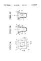
- FIG. 3A is a front view of a male member, the other part of the fixing clip.
- FIG. 3B is a side view of the male member.
- FIG. 3C is a cross section of the male member taken along line 3C--3C in FIG. 3B.
- FIG. 4 is an explanatory view showing the state in which a leading end of a shank of the male member is inserted into a blind inner hole of the female member.
- FIG. 5 is a cross section of an essential part showing the state in which a fitting part is fixed onto a panel.
- FIG. 6 is an explanatory view showing the state in which a pair of protruding shoulders formed on the shank of the male member have been brought into engagement with corresponding engaging projections.
- FIG. 7 is an explanatory view showing the state in which the pair of protruding shoulders of the male member have been relieved of the engagement with the engaging projections in the blind hole of the female member in consequence of the rotation of the male member.
- FIG. 8 is an explanatory view showing one example of the structure of a sliding split die for the formation of the female member.
- the fixing clip comprises two parts, i.e. a female member 1 having an inner hole 4 bored from a flange 2 through a barrel 3 thereof and a male member 11 provided with a shank 12 fit for insertion into the inner hole 4 of the female member.
- the female member 1 is a one-piece mold of synthetic resin.
- the inner bole 4 bored in the barrel 3 assuming a regular rectangular cross section is formed in the shape of a blind hole regularly rectangular in cross section and open only on the side of the flange 2, which is similar in cross section.
- a pair of engaging projections 5 have a distance L1 therebetween and are formed on the diagonally opposed inner wall surfaces of the blind inner hole 4 at mutually staggered positions.
- protuberances 6 adapted for engagement with the edge of a fitting hole H2 formed beforehand in a given panel P2 (FIG. 5) are formed with one on each of the outer wall surfaces of the barrel 3.
- Notches 7 serve as marks and are formed at the centers of the edges of the flange 2 on the sides of the engaging projections 5.
- the pair of engaging projections 5 are formed so as to occupy one half of the respective areas of the relevant wall surfaces of the barrel 3; their lower edges assume a rectangular shape.
- the male member 11 is likewise a one-piece mold of synthetic resin. As shown in FIGS. 3A through 3C, the opposed portions on a leading end 12a of the shank 12, pendent from an enlarged head 13, are chamfered so as to give to the leading end 12a a linear width L2 smaller than the distance L1 separating the pair of engaging projections 5 of the female member 1.
- a pair of protruding shoulders 14 are provided in the same width as the width L2 of the leading end 12a and in a total length L3 slightly larger than the distance L1 between the pair of engaging projections 5 of the female member 1 so that the protruding shoulders 14 can be engaged with the engaging projections 5 of the female member 1, and Guide faces 15 converging downward are formed on the lower edges of the pair of protruding shoulders 14 and, at the same time, tapered cut faces 16 adapted to allow rotation of the male member 11 when the male member 11 is to be extracted from the female member 1 are continuously formed on the lateral parts located on the diagonal line of the guide faces 15.
- the enlarged head 13 is provided in the upper face thereof with a manipulating groove 17 for admitting the leading end of a tool (not shown).
- the use of the female member 1 and the male member 11 constructed as described above in fixing a fitting part P1 having a through hole H1 (FIG. 5), such as a bumper of an automobile, to the panel P2 is effected by tacking the barrel 3 of the female member 1 to the fitting hole H2 of the panel P2.
- a nipping action is produced jointly by the flange 2 and the protuberances 6.
- the through hole H1 of the fitting part P1 is made to coincide with the blind inner hole 4 of the barrel 3.
- the shank 12 of the male member 11 is inserted into the blind inner hole 4 of the barrel 3 while keeping the protruding shoulders 14 in alignment with the positions of the notches 7.
- the shank 12 of the male member 11 is easily inserted into the blind inner hole 4 without the use of very strong force because the pair of protruding shoulders 14 are allowed to smoothly pass the engaging projections 5, positioned as staggered, while, as shown in FIG. 4, spreading outward the centers of the wall surfaces on which the engaging projections 5 are provided.
- the removal of the fixed fitting part P1 from the panel P1 is effected by inserting the leading end of a tool (not shown) into the manipulating groove 17 provided in the enlarged head 13 of the male member 11 and rotating the male member 11 by an angle of about 90 degrees inside the blind inner hole 4 in a direction in which the cut faces 16 are absent (the direction of the arrow shown in FIG. 6).
- the pair of protruding shoulders 14 disposed on the leading end 12a of smaller width of the shank 12 are rotated in the same direction and gradually relieved of engagement with the corresponding engaging projections 5, and are eventually positioned, as shown in FIG. 7, between the engaging projections 5 owing to the presence of the cut faces 16 formed in a diagonal pattern.
- fitting part P1 can be easily removed from the panel P2 by simply pulling the shank 12 of the male member 11 out of the blind inner hole 4.
- the pair of engaging projections 5 for engagement with the protruding shoulders 14 on the male member 11 are disposed on the opposed wall surfaces of the barrel 3 of the female member 1 in such a manner that their positions are staggered from each other by within one half of the areas of the wall surfaces in the embodiment described above, the pair of engaging projections 5 may be so disposed on the entire area of the opposed wall surfaces as to be opposed with perfect coincidence.
- the pair of engaging projections 5 are so disposed as to occupy staggered positions as in the embodiment described above, they offer the following advantage in addition to the advantage of allowing a decrease in the force of insertion.
- the lower edges thereof be rectangular.
- this structure is capable of infallibly conferring a thickness T (FIG. 8) necessary in terms of strength on at least a part 21b of a split segment 21 from which the engaging projections 5 are absent, let alone a position 21a of the split segment 21 opposed to the engaging projections 5. This fact contributes enormous to increasing the durability of the split die.
- the formation of the rectangular lower edge implemented as described above therefore, obviates the necessity for enlarging the split die structure in due respect of the wall thickness of the split segment 21 required for necessary durability as in the case of disposing the pair of engaging projections 5 on the entire areas of the opposed wall surfaces of the blind inner hole 4 to permit perfect coincidence.
- the female member 1 is allowed to have an arbitrarily selected size and is liberated from the possibility of being subject to a design restriction.
- This invention when necessary, may be otherwise variously embodied and practiced even with respect to the other component parts within the scope of this invention.
- the shank 12 is circular in cross section.
- this cross sectional shape is such that the circle has substantially the same diameter as one side of the regular rectangle of the lateral cross section of the blind inner hole of the female member 11.
- this invention enables the fixing clip to have perfect waterproofness without requiring the use of such a waterproofing cap as is used in the prior art fixing clip. At the same time, it permits easy removal of a fitting part from a panel and naturally allows the fixing clip to enjoy enhanced practical serviceability. Since the fixing clip of the present invention only requires the male member thereof to be rotated by an angle of 90 degrees in attaining the necessary removal of the fitting part, the work of removing the fitting part is facilitated to a great extent.
- the sliding split die structure is capable of amply securing a necessary thickness for the split segment, and also contributes to increasing the durability of the split die itself.
Abstract
Description
Claims (10)
Applications Claiming Priority (2)
| Application Number | Priority Date | Filing Date | Title |
|---|---|---|---|
| JP7-114070 | 1995-04-17 | ||
| JP11407095A JP3297972B2 (en) | 1995-04-17 | 1995-04-17 | Securing clip |
Publications (1)
| Publication Number | Publication Date |
|---|---|
| US5718549A true US5718549A (en) | 1998-02-17 |
Family
ID=14628294
Family Applications (1)
| Application Number | Title | Priority Date | Filing Date |
|---|---|---|---|
| US08/633,552 Expired - Fee Related US5718549A (en) | 1995-04-17 | 1996-04-17 | Releasable two-part fixing clip |
Country Status (2)
| Country | Link |
|---|---|
| US (1) | US5718549A (en) |
| JP (1) | JP3297972B2 (en) |
Cited By (56)
| Publication number | Priority date | Publication date | Assignee | Title |
|---|---|---|---|---|
| US5975820A (en) * | 1998-11-03 | 1999-11-02 | Illinois Tool Works Inc. | Two-piece pin and grommet |
| US6007296A (en) * | 1997-03-08 | 1999-12-28 | Abb Research Ltd. | Guide blade for steam turbines |
| US6206606B1 (en) * | 1996-07-26 | 2001-03-27 | Piolax Inc. | Fixing device for rod body |
| US6237970B1 (en) * | 1999-04-23 | 2001-05-29 | Constantinos J. Joannou | Latch fastener mechanism for thin sheet materials |
| US6481682B2 (en) * | 2000-07-04 | 2002-11-19 | Nifco Inc. | Plate member mounting structure |
| EP1291534A1 (en) * | 2001-09-07 | 2003-03-12 | ITW Sverige AB | Releasable clip |
| US20030093883A1 (en) * | 2001-11-21 | 2003-05-22 | Gibbons Matthew H. | Plastic retaining clip for rib attachment |
| US6585027B1 (en) | 2001-12-19 | 2003-07-01 | Vista Products, Inc. | Arched window shade support device |
| US6676177B2 (en) * | 2001-05-14 | 2004-01-13 | Lucent Technologies Inc. | Quarter turn latch |
| US20040047711A1 (en) * | 2002-09-11 | 2004-03-11 | United Technologies Corporation | Fastener assembly for use with composite articles |
| US20040091334A1 (en) * | 2002-11-07 | 2004-05-13 | Nifco Inc. | Connector with male part for final fixing |
| US20040139584A1 (en) * | 2003-01-17 | 2004-07-22 | Gibbons Matthew H. | Two-piece interior trim retainer |
| EP1452745A1 (en) * | 2003-02-28 | 2004-09-01 | Metzeler Automotive Profile Systems GmbH | Attachment-clip, in particular for fastening a gasket and/or guidance profile for a windowpane at the body of a motor vehicle |
| US6796006B2 (en) * | 2002-04-25 | 2004-09-28 | Illinois Tool Works Inc. | Rib clip |
| US20040223826A1 (en) * | 2003-04-03 | 2004-11-11 | Lisi Automotive Rapid | Fastening device, particularly for holding together a stack of at least two panels |
| US20040253901A1 (en) * | 2003-05-14 | 2004-12-16 | Joseph Donahue | Modular construction system and method of constructing toy structures |
| US20050123379A1 (en) * | 2003-12-09 | 2005-06-09 | International Business Machines Corporation | Locking turn pin |
| US20050202705A1 (en) * | 2004-02-24 | 2005-09-15 | Burmahln Jedediah A. | Snap-in latch housing assembly |
| US20050220561A1 (en) * | 2004-03-30 | 2005-10-06 | Piolax, Inc. | Clipping device |
| US20050276677A1 (en) * | 2002-03-25 | 2005-12-15 | Andersson Goeran | Load carrier support |
| US20060198714A1 (en) * | 2005-03-02 | 2006-09-07 | Itw De France | Fastener adapted to be fixed in a cavity of predetermined contour |
| US20060201636A1 (en) * | 2005-03-09 | 2006-09-14 | Morrison Christine B | Window treatment hanger having arcuate rod releasable from wall mounts |
| WO2007069036A1 (en) * | 2005-12-15 | 2007-06-21 | Itw Automotive Products Gmbh & Co. Kg | A fastening device for the releasable fastening of a flat structural member to a support structure |
| US20080011930A1 (en) * | 2006-07-13 | 2008-01-17 | Yazaki Corporation | Attaching structure |
| US20080047113A1 (en) * | 2002-12-09 | 2008-02-28 | Lipniarski David J | Indented female blow-molded connector and male connector and method |
| US20080050202A1 (en) * | 2006-08-22 | 2008-02-28 | Yu-Chiao Liu | Fastening device |
| US20080056816A1 (en) * | 2006-09-06 | 2008-03-06 | Rainer Sussenbach | Quick connect closure for connecting two structural members |
| US20090058113A1 (en) * | 2007-08-27 | 2009-03-05 | Shoap Stephen D | Method and Apparatus for a Shared Crumple Zone |
| US20090074534A1 (en) * | 2007-09-17 | 2009-03-19 | Hong Fu Jin Precision Industry (Shenzhen) Co., Ltd. | Supporting apparatus for electrical apparatus |
| US20090162163A1 (en) * | 2006-04-19 | 2009-06-25 | Nifco Inc. | Article Installation Device |
| US20090263210A1 (en) * | 2008-04-18 | 2009-10-22 | Twa Automotive Electronics & Components Gmbh | Connecting assembly for fastening an add-on element on a carrier element |
| US20100040410A1 (en) * | 2008-07-17 | 2010-02-18 | King Furniture (Australia) Pty Ltd | accessory attaching system |
| US20100284760A1 (en) * | 2009-05-08 | 2010-11-11 | E-B Display Company, Inc. | Fastener for attaching metal parts |
| WO2010130176A1 (en) * | 2009-05-15 | 2010-11-18 | 华为技术有限公司 | Quick-locking fastener |
| CN102947604A (en) * | 2010-06-21 | 2013-02-27 | 株式会社利富高 | Clamp |
| US20130091669A1 (en) * | 2010-04-27 | 2013-04-18 | Nifco Inc. | Member fastening structure and clip for fastening member |
| WO2013135400A1 (en) * | 2012-03-13 | 2013-09-19 | Siemens Ag Österreich | Retaining pin |
| CN103917789A (en) * | 2011-11-11 | 2014-07-09 | 株式会社利富高 | Clip |
| US20150023759A1 (en) * | 2013-07-17 | 2015-01-22 | II James W. Klopfenstein | Fastener for Attaching Objects to Channeled Members |
| US20150104248A1 (en) * | 2012-03-02 | 2015-04-16 | Johnson Controls Gmbh | Play-free connection device |
| US9010059B2 (en) * | 2011-01-31 | 2015-04-21 | Value Chain Network (Hong Kong) Limited | Building blocks and building block fasteners |
| US20150184419A1 (en) * | 2013-12-30 | 2015-07-02 | Alan Qing-Lin Zhu | Elastic non-metal clip and assembled fence including the same |
| US20150337882A1 (en) * | 2013-01-31 | 2015-11-26 | Daiwa Kasei Kogyo Kabushiki Kaisha | Clip attachment structure |
| US20160059898A1 (en) * | 2014-08-27 | 2016-03-03 | GM Global Technology Operations LLC | Locator cam assembly |
| US9599140B2 (en) | 2014-08-28 | 2017-03-21 | Newfrey Llc | Plastic serviceable screw grommet and related methods |
| USD783385S1 (en) * | 2014-06-20 | 2017-04-11 | Alan Qing-Lin Zhu | Fence clip |
| EP3159552A1 (en) * | 2015-10-19 | 2017-04-26 | Kathrein Werke KG | Expanding rivet connection and method of mounting the same |
| US20180119715A1 (en) * | 2016-11-02 | 2018-05-03 | Toyota Jidosha Kabushiki Kaisha | Screw grommet attachment structure |
| US9982699B2 (en) * | 2012-11-15 | 2018-05-29 | Illinois Tool Works Inc. | Energy absorption rotatable fastener |
| US20190092261A1 (en) * | 2017-09-26 | 2019-03-28 | Sahas Chkilam | Protection cusion concealment system for vehicle roll bar assembly |
| CN110185687A (en) * | 2019-05-22 | 2019-08-30 | 安徽江淮汽车集团股份有限公司 | A kind of push-in pin shaft |
| US10738807B2 (en) * | 2012-04-26 | 2020-08-11 | Bayerische Motoren Werke Aktiengesellschaft | Clip element and component connection |
| US20210190109A1 (en) * | 2019-12-18 | 2021-06-24 | Illinois Tool Works Inc. | W-base fastener and locator cap |
| US20210190121A1 (en) * | 2016-02-26 | 2021-06-24 | Centrix Inc. | Expandable collet bodies with sectional finger-based antirotation feature, clips, inserts and systems therof |
| US20210355979A1 (en) * | 2018-10-02 | 2021-11-18 | Böllhoff Verbindungstechnik GmbH | Plug-in coupling with tolerance compensation |
| US20210381536A1 (en) * | 2020-06-03 | 2021-12-09 | Illinois Tool Works Inc. | Fastener |
Families Citing this family (3)
| Publication number | Priority date | Publication date | Assignee | Title |
|---|---|---|---|---|
| KR100410840B1 (en) * | 2001-05-14 | 2003-12-18 | 현대자동차주식회사 | Panel fixing instrument for car |
| JP5001902B2 (en) * | 2008-03-12 | 2012-08-15 | 株式会社ニフコ | Connecting device |
| CN103807263A (en) * | 2012-11-07 | 2014-05-21 | 鸿富锦精密工业(深圳)有限公司 | Locking mechanism |
Citations (9)
| Publication number | Priority date | Publication date | Assignee | Title |
|---|---|---|---|---|
| US2385180A (en) * | 1943-09-30 | 1945-09-18 | Camloc Fastener Corp | Fastener |
| US2879574A (en) * | 1955-09-30 | 1959-03-31 | Victor F Zahodiakin | Fastening devices |
| JPS6137847A (en) * | 1984-07-20 | 1986-02-22 | ヘキスト・アクチエンゲゼルシヤフト | Water soluble triphene dioxane compound, its production and its use as dye |
| US4743152A (en) * | 1984-09-07 | 1988-05-10 | Nifco Inc. | Screw grommet |
| JPH0250508A (en) * | 1988-08-10 | 1990-02-20 | Matsushita Electric Ind Co Ltd | Digital signal processor |
| US4971500A (en) * | 1990-03-19 | 1990-11-20 | Illinois Tool Works Inc. | Enclosed plastic screw grommet |
| US5193961A (en) * | 1992-02-12 | 1993-03-16 | Illinois Tool Works Inc. | Pin and grommet |
| US5222852A (en) * | 1992-03-20 | 1993-06-29 | Nissan Research & Development | Quick release clip-in-grommet fastener permitting limited sliding movement between objects fastened thereby |
| US5468109A (en) * | 1993-02-11 | 1995-11-21 | Franco Ferrari | Quick removable fasteners in particular for furniture |
-
1995
- 1995-04-17 JP JP11407095A patent/JP3297972B2/en not_active Expired - Fee Related
-
1996
- 1996-04-17 US US08/633,552 patent/US5718549A/en not_active Expired - Fee Related
Patent Citations (9)
| Publication number | Priority date | Publication date | Assignee | Title |
|---|---|---|---|---|
| US2385180A (en) * | 1943-09-30 | 1945-09-18 | Camloc Fastener Corp | Fastener |
| US2879574A (en) * | 1955-09-30 | 1959-03-31 | Victor F Zahodiakin | Fastening devices |
| JPS6137847A (en) * | 1984-07-20 | 1986-02-22 | ヘキスト・アクチエンゲゼルシヤフト | Water soluble triphene dioxane compound, its production and its use as dye |
| US4743152A (en) * | 1984-09-07 | 1988-05-10 | Nifco Inc. | Screw grommet |
| JPH0250508A (en) * | 1988-08-10 | 1990-02-20 | Matsushita Electric Ind Co Ltd | Digital signal processor |
| US4971500A (en) * | 1990-03-19 | 1990-11-20 | Illinois Tool Works Inc. | Enclosed plastic screw grommet |
| US5193961A (en) * | 1992-02-12 | 1993-03-16 | Illinois Tool Works Inc. | Pin and grommet |
| US5222852A (en) * | 1992-03-20 | 1993-06-29 | Nissan Research & Development | Quick release clip-in-grommet fastener permitting limited sliding movement between objects fastened thereby |
| US5468109A (en) * | 1993-02-11 | 1995-11-21 | Franco Ferrari | Quick removable fasteners in particular for furniture |
Cited By (89)
| Publication number | Priority date | Publication date | Assignee | Title |
|---|---|---|---|---|
| US6206606B1 (en) * | 1996-07-26 | 2001-03-27 | Piolax Inc. | Fixing device for rod body |
| US6007296A (en) * | 1997-03-08 | 1999-12-28 | Abb Research Ltd. | Guide blade for steam turbines |
| EP0863296A3 (en) * | 1997-03-08 | 2001-03-21 | Abb Research Ltd. | Guide vane for steam turbines |
| US5975820A (en) * | 1998-11-03 | 1999-11-02 | Illinois Tool Works Inc. | Two-piece pin and grommet |
| US6237970B1 (en) * | 1999-04-23 | 2001-05-29 | Constantinos J. Joannou | Latch fastener mechanism for thin sheet materials |
| US6481682B2 (en) * | 2000-07-04 | 2002-11-19 | Nifco Inc. | Plate member mounting structure |
| US6676177B2 (en) * | 2001-05-14 | 2004-01-13 | Lucent Technologies Inc. | Quarter turn latch |
| US6752576B2 (en) | 2001-09-07 | 2004-06-22 | Itw Sverige Ab | Dismountable clip, and a tool and method for producing the clip |
| EP1291534A1 (en) * | 2001-09-07 | 2003-03-12 | ITW Sverige AB | Releasable clip |
| US20030093883A1 (en) * | 2001-11-21 | 2003-05-22 | Gibbons Matthew H. | Plastic retaining clip for rib attachment |
| US6585027B1 (en) | 2001-12-19 | 2003-07-01 | Vista Products, Inc. | Arched window shade support device |
| US20050276677A1 (en) * | 2002-03-25 | 2005-12-15 | Andersson Goeran | Load carrier support |
| US6796006B2 (en) * | 2002-04-25 | 2004-09-28 | Illinois Tool Works Inc. | Rib clip |
| US6773215B2 (en) * | 2002-09-11 | 2004-08-10 | United Technologies Corporation | Fastener assembly for use with composite articles |
| US20040047711A1 (en) * | 2002-09-11 | 2004-03-11 | United Technologies Corporation | Fastener assembly for use with composite articles |
| US6955514B2 (en) * | 2002-11-07 | 2005-10-18 | Nifco Inc. | Connector with male part for final fixing |
| US20040091334A1 (en) * | 2002-11-07 | 2004-05-13 | Nifco Inc. | Connector with male part for final fixing |
| US7526841B2 (en) * | 2002-12-09 | 2009-05-05 | Confer Plastics, Inc. | Indented female blow-molded connector and male connector and method |
| US20080047113A1 (en) * | 2002-12-09 | 2008-02-28 | Lipniarski David J | Indented female blow-molded connector and male connector and method |
| US20040139584A1 (en) * | 2003-01-17 | 2004-07-22 | Gibbons Matthew H. | Two-piece interior trim retainer |
| EP1452745A1 (en) * | 2003-02-28 | 2004-09-01 | Metzeler Automotive Profile Systems GmbH | Attachment-clip, in particular for fastening a gasket and/or guidance profile for a windowpane at the body of a motor vehicle |
| US7207758B2 (en) * | 2003-04-03 | 2007-04-24 | Lisi Automotive Rapid | Fastening device, particularly for holding together a stack of at least two panels |
| US20040223826A1 (en) * | 2003-04-03 | 2004-11-11 | Lisi Automotive Rapid | Fastening device, particularly for holding together a stack of at least two panels |
| US6966813B2 (en) * | 2003-05-14 | 2005-11-22 | Joseph Donahue | Modular construction system and method of constructing toy structures |
| US20040253901A1 (en) * | 2003-05-14 | 2004-12-16 | Joseph Donahue | Modular construction system and method of constructing toy structures |
| US20050123379A1 (en) * | 2003-12-09 | 2005-06-09 | International Business Machines Corporation | Locking turn pin |
| US6955515B2 (en) * | 2003-12-09 | 2005-10-18 | International Business Machines Corporation | Locking turn pin |
| US20050202705A1 (en) * | 2004-02-24 | 2005-09-15 | Burmahln Jedediah A. | Snap-in latch housing assembly |
| US7497487B2 (en) * | 2004-02-24 | 2009-03-03 | Southco, Inc. | Snap-in latch housing assembly |
| US7736107B2 (en) * | 2004-03-30 | 2010-06-15 | Piolax, Inc. | Clipping device |
| US20050220561A1 (en) * | 2004-03-30 | 2005-10-06 | Piolax, Inc. | Clipping device |
| US20060198714A1 (en) * | 2005-03-02 | 2006-09-07 | Itw De France | Fastener adapted to be fixed in a cavity of predetermined contour |
| US7553116B2 (en) * | 2005-03-02 | 2009-06-30 | Itw De France | Fastener adapted to be fixed in a cavity of predetermined contour |
| US20060201636A1 (en) * | 2005-03-09 | 2006-09-14 | Morrison Christine B | Window treatment hanger having arcuate rod releasable from wall mounts |
| WO2007069036A1 (en) * | 2005-12-15 | 2007-06-21 | Itw Automotive Products Gmbh & Co. Kg | A fastening device for the releasable fastening of a flat structural member to a support structure |
| US20090162163A1 (en) * | 2006-04-19 | 2009-06-25 | Nifco Inc. | Article Installation Device |
| US7740432B2 (en) | 2006-04-19 | 2010-06-22 | Nifco Inc. | Article installation device |
| DE102007032554B4 (en) * | 2006-07-13 | 2012-12-06 | Yazaki Corp. | fastening device |
| US20080011930A1 (en) * | 2006-07-13 | 2008-01-17 | Yazaki Corporation | Attaching structure |
| US7562857B2 (en) * | 2006-07-13 | 2009-07-21 | Yazaki Corporation | Attaching structure |
| US20080050202A1 (en) * | 2006-08-22 | 2008-02-28 | Yu-Chiao Liu | Fastening device |
| US20080056816A1 (en) * | 2006-09-06 | 2008-03-06 | Rainer Sussenbach | Quick connect closure for connecting two structural members |
| EP1898105A3 (en) * | 2006-09-06 | 2010-05-26 | Böllhoff Verbindungstechnik GmbH | Quick locking device for connecting two components |
| US7699347B2 (en) * | 2007-08-27 | 2010-04-20 | Shoap Stephen D | Method and apparatus for a shared crumple zone |
| US20090058136A1 (en) * | 2007-08-27 | 2009-03-05 | Shoap Stephen D | Method and Apparatus for a Shared Crumple Zone |
| US7695018B2 (en) * | 2007-08-27 | 2010-04-13 | Shoap Stephen D | Method and apparatus for a shared crumple zone |
| US20090058113A1 (en) * | 2007-08-27 | 2009-03-05 | Shoap Stephen D | Method and Apparatus for a Shared Crumple Zone |
| US20090074534A1 (en) * | 2007-09-17 | 2009-03-19 | Hong Fu Jin Precision Industry (Shenzhen) Co., Ltd. | Supporting apparatus for electrical apparatus |
| CN101561006B (en) * | 2008-04-18 | 2013-01-02 | Trw车辆电气与零件有限公司 | Connection component for attaching an extension element to a carrier element |
| US20090263210A1 (en) * | 2008-04-18 | 2009-10-22 | Twa Automotive Electronics & Components Gmbh | Connecting assembly for fastening an add-on element on a carrier element |
| US20100040410A1 (en) * | 2008-07-17 | 2010-02-18 | King Furniture (Australia) Pty Ltd | accessory attaching system |
| US20100284760A1 (en) * | 2009-05-08 | 2010-11-11 | E-B Display Company, Inc. | Fastener for attaching metal parts |
| WO2010130176A1 (en) * | 2009-05-15 | 2010-11-18 | 华为技术有限公司 | Quick-locking fastener |
| US20130091669A1 (en) * | 2010-04-27 | 2013-04-18 | Nifco Inc. | Member fastening structure and clip for fastening member |
| US8926244B2 (en) * | 2010-04-27 | 2015-01-06 | Nifco Inc. | Member fastening structure and clip for fastening member |
| CN102947604A (en) * | 2010-06-21 | 2013-02-27 | 株式会社利富高 | Clamp |
| US9004415B2 (en) | 2010-06-21 | 2015-04-14 | Nifco Inc. | Clamp |
| CN102947604B (en) * | 2010-06-21 | 2015-12-16 | 株式会社利富高 | Clip |
| US9010059B2 (en) * | 2011-01-31 | 2015-04-21 | Value Chain Network (Hong Kong) Limited | Building blocks and building block fasteners |
| CN103917789A (en) * | 2011-11-11 | 2014-07-09 | 株式会社利富高 | Clip |
| CN103917789B (en) * | 2011-11-11 | 2016-01-27 | 株式会社利富高 | clip |
| US20150104248A1 (en) * | 2012-03-02 | 2015-04-16 | Johnson Controls Gmbh | Play-free connection device |
| US9254794B2 (en) * | 2012-03-02 | 2016-02-09 | Johnson Controls Gmbh | Play-free connection device |
| WO2013135400A1 (en) * | 2012-03-13 | 2013-09-19 | Siemens Ag Österreich | Retaining pin |
| US10738807B2 (en) * | 2012-04-26 | 2020-08-11 | Bayerische Motoren Werke Aktiengesellschaft | Clip element and component connection |
| US9982699B2 (en) * | 2012-11-15 | 2018-05-29 | Illinois Tool Works Inc. | Energy absorption rotatable fastener |
| US20150337882A1 (en) * | 2013-01-31 | 2015-11-26 | Daiwa Kasei Kogyo Kabushiki Kaisha | Clip attachment structure |
| US9938997B2 (en) * | 2013-01-31 | 2018-04-10 | Daiwa Kasei Kogyo Kabushiki Kaisha | Clip attachment structure |
| US20150023759A1 (en) * | 2013-07-17 | 2015-01-22 | II James W. Klopfenstein | Fastener for Attaching Objects to Channeled Members |
| US9022712B2 (en) * | 2013-07-17 | 2015-05-05 | II James W. Klopfenstein | Fastener for attaching objects to channeled members |
| US9234368B2 (en) * | 2013-12-30 | 2016-01-12 | Alan Qing-Lin Zhu | Elastic non-metal clip and assembled fence including the same |
| US20150184419A1 (en) * | 2013-12-30 | 2015-07-02 | Alan Qing-Lin Zhu | Elastic non-metal clip and assembled fence including the same |
| USD783385S1 (en) * | 2014-06-20 | 2017-04-11 | Alan Qing-Lin Zhu | Fence clip |
| US20160059898A1 (en) * | 2014-08-27 | 2016-03-03 | GM Global Technology Operations LLC | Locator cam assembly |
| US9599140B2 (en) | 2014-08-28 | 2017-03-21 | Newfrey Llc | Plastic serviceable screw grommet and related methods |
| EP3159552A1 (en) * | 2015-10-19 | 2017-04-26 | Kathrein Werke KG | Expanding rivet connection and method of mounting the same |
| CN106837966A (en) * | 2015-10-19 | 2017-06-13 | 凯瑟雷恩工厂两合公司 | The installation method that expansive rivet is connected and expansive rivet is connected |
| CN106837966B (en) * | 2015-10-19 | 2019-08-09 | 凯仕林欧洲股份有限公司 | Expansive rivet connects the installation method connected with expansive rivet |
| US11692580B2 (en) * | 2016-02-26 | 2023-07-04 | Centrix Inc. | Expandable collet bodies with sectional finger-based anti-rotation feature, clips, inserts and systems thereof |
| US20210190121A1 (en) * | 2016-02-26 | 2021-06-24 | Centrix Inc. | Expandable collet bodies with sectional finger-based antirotation feature, clips, inserts and systems therof |
| US20180119715A1 (en) * | 2016-11-02 | 2018-05-03 | Toyota Jidosha Kabushiki Kaisha | Screw grommet attachment structure |
| US10471915B2 (en) * | 2017-09-26 | 2019-11-12 | Fca Us Llc | Protection cushion concealment system for vehicle roll bar assembly |
| US20190092261A1 (en) * | 2017-09-26 | 2019-03-28 | Sahas Chkilam | Protection cusion concealment system for vehicle roll bar assembly |
| US20210355979A1 (en) * | 2018-10-02 | 2021-11-18 | Böllhoff Verbindungstechnik GmbH | Plug-in coupling with tolerance compensation |
| CN110185687A (en) * | 2019-05-22 | 2019-08-30 | 安徽江淮汽车集团股份有限公司 | A kind of push-in pin shaft |
| US20210190109A1 (en) * | 2019-12-18 | 2021-06-24 | Illinois Tool Works Inc. | W-base fastener and locator cap |
| US11644052B2 (en) * | 2019-12-18 | 2023-05-09 | Illinois Tool Works Inc. | W-base fastener and locator cap |
| US20210381536A1 (en) * | 2020-06-03 | 2021-12-09 | Illinois Tool Works Inc. | Fastener |
| US11692567B2 (en) * | 2020-06-03 | 2023-07-04 | Illinois Tool Works Inc. | Fastener |
Also Published As
| Publication number | Publication date |
|---|---|
| JP3297972B2 (en) | 2002-07-02 |
| JPH08284925A (en) | 1996-11-01 |
Similar Documents
| Publication | Publication Date | Title |
|---|---|---|
| US5718549A (en) | Releasable two-part fixing clip | |
| US7736107B2 (en) | Clipping device | |
| US7013612B2 (en) | Multi-piece clamp for standing seams | |
| US7207759B2 (en) | Fastener for panels or the like | |
| US4639175A (en) | Self-sealing expansion rivet assembly | |
| US5632581A (en) | Clip | |
| US4668145A (en) | Fastener for coupling together two panels in face-to-face relation | |
| US5361925A (en) | Terminal box | |
| US4647262A (en) | Removable expanding fastener | |
| US5370484A (en) | Push rivet having unfastening means | |
| USRE33809E (en) | Fastener | |
| US4420859A (en) | Two-part panel fastener | |
| US20050002760A1 (en) | Blind rivet fastener and workpiece assembly using same | |
| US4306824A (en) | Blind rivet | |
| US4342136A (en) | Apparatus for fastening inside handle cover to automobile door | |
| US20190219086A1 (en) | Rivet fastener assembly and method of use thereof | |
| US6439527B1 (en) | Fitting for holding an upright suspension rod to a ceiling wall | |
| US6152667A (en) | Blind aperture fastener | |
| US20220213914A1 (en) | Rivet fastener assembly and method of use thereof | |
| JPH094619A (en) | Fixing clip | |
| JP2958276B2 (en) | Vehicle bumper | |
| JPH0312936Y2 (en) | ||
| JPH04138115U (en) | Fixed structure of plate material | |
| US20040160057A1 (en) | Base tee connection | |
| JP2509814Y2 (en) | Fastener |
Legal Events
| Date | Code | Title | Description |
|---|---|---|---|
| AS | Assignment |
Owner name: NISSAN MOTOR CO., LTD., JAPAN Free format text: ASSIGNMENT OF ASSIGNORS INTEREST;ASSIGNORS:NODA, YUSUKE;ARISAKA, OOMI;ARAKAWA, KOJI;REEL/FRAME:007973/0795 Effective date: 19960405 Owner name: PIOLAX, INC., JAPAN Free format text: ASSIGNMENT OF ASSIGNORS INTEREST;ASSIGNORS:NODA, YUSUKE;ARISAKA, OOMI;ARAKAWA, KOJI;REEL/FRAME:007973/0795 Effective date: 19960405 |
|
| FPAY | Fee payment |
Year of fee payment: 4 |
|
| FEPP | Fee payment procedure |
Free format text: PAYOR NUMBER ASSIGNED (ORIGINAL EVENT CODE: ASPN); ENTITY STATUS OF PATENT OWNER: LARGE ENTITY |
|
| FPAY | Fee payment |
Year of fee payment: 8 |
|
| REMI | Maintenance fee reminder mailed | ||
| LAPS | Lapse for failure to pay maintenance fees | ||
| LAPS | Lapse for failure to pay maintenance fees |
Free format text: PATENT EXPIRED FOR FAILURE TO PAY MAINTENANCE FEES (ORIGINAL EVENT CODE: EXP.); ENTITY STATUS OF PATENT OWNER: LARGE ENTITY |
|
| STCH | Information on status: patent discontinuation |
Free format text: PATENT EXPIRED DUE TO NONPAYMENT OF MAINTENANCE FEES UNDER 37 CFR 1.362 |
|
| FP | Lapsed due to failure to pay maintenance fee |
Effective date: 20100217 |