US7460285B2 - Load allocation when executing image processing using parallel processing - Google Patents
Load allocation when executing image processing using parallel processing Download PDFInfo
- Publication number
- US7460285B2 US7460285B2 US11/212,430 US21243005A US7460285B2 US 7460285 B2 US7460285 B2 US 7460285B2 US 21243005 A US21243005 A US 21243005A US 7460285 B2 US7460285 B2 US 7460285B2
- Authority
- US
- United States
- Prior art keywords
- process segment
- processing
- partial image
- type
- allocated
- Prior art date
- Legal status (The legal status is an assumption and is not a legal conclusion. Google has not performed a legal analysis and makes no representation as to the accuracy of the status listed.)
- Expired - Fee Related, expires
Links
Images


Classifications
-
- H—ELECTRICITY
- H04—ELECTRIC COMMUNICATION TECHNIQUE
- H04N—PICTORIAL COMMUNICATION, e.g. TELEVISION
- H04N1/00—Scanning, transmission or reproduction of documents or the like, e.g. facsimile transmission; Details thereof
- H04N1/46—Colour picture communication systems
Definitions
- the present invention relates to technology for executing parallel image processing.
- JP2000-293674A JP2000-293674A
- JP2000-293674A JP2000-293674A
- JP2000-293674A disclosed is technology for executing rasterizing (data rearranging) processing and halftone processing according to the processing contents using separate threads.
- An object of the present invention is to provide a technology for efficiently executing parallel image processing.
- the present invention is related to Japanese patent applications No. 2004-245085, filed Aug. 25, 2004 and No. 2004-245078, filed Aug. 25, 2004; the contents of which are incorporated herein by reference.
- the present invention performs specified processes for image processing.
- First-type processing is executed on a first partial image data representing a partial image to generate a second partial image data.
- second-type processing is executed on the second partial image data.
- the execution of the first and second-type processing are repeated on a plurality of partial images aligned to be adjacent to each other using a plurality of processing units respectively capable of executing the first and second-type process segments.
- a first-type process segment and a second-type process segment are executed parallel using the plurality of processing units.
- the first-type process segment relates to i-th partial image.
- the second-type process segment relates to any of (i+1)-th to (i+p)-th partial images (i is a positive integer, and p is a positive integer).
- the first partial image data may be represented by a first color system.
- the first partial image data may be converted into image data represented by a second color system having M (M is an integer of 2 or greater) color components to generate M types of the second partial image data corresponding to the color components.
- the second-type process segment may be halftone processing.
- Process segments of a subject process segment set are allocated to the plurality of processing units in sequence.
- the subject process segment set includes: at least one second-type process segment which relates to i-th (i is a positive integer) partial image but has not yet been allocated to one of the processing units; and a plurality of first-type process segments which relate to (i+1)-th to (i+p)-th (p is a positive integer) partial images but have not yet been allocated to the processing units.
- the first and second-type process segments are executed in the allocated sequence on allocated processing units respectively.
- process segments can be allocated to the processing units so that the second-type process segments relating to the i-th (i is a positive integer) partial images and the first-type process segments relating to any of the (i+1)-th to (i+p)-th (p is a positive integer) partial images are likely to be executed parallel.
- a load of the first-type process segment of the subject process segment set is estimated based on execution results of a preceding first-type process segment.
- a load of the second-type process segment of the subject process segment set is estimated based on execution results of a preceding second-type process segment of same type.
- one process segment included in the subject process segment set is selected according to a priority sequence of decreasing estimated loads. Then the selected process segment is allocated to a processing unit with a lowest total estimated load of process segments already allocated. The selection and allocation are repeated. With this aspect, it is possible to equalize the load between each processing unit using accurately estimated loads based on the immediately prior execution results.
- One process segment is selected from among the subject process segment set.
- the selected process segment is allocated to one of the plurality of processing units. Then the selected process segment is executed on the allocated processing units. The selection, the allocation and the execution are repeated.
- the second-type process segments relating to i-th (i is a positive integer) partial images and the first-type process segments relating to any of the (i+1)-th to the (i+p)-th (p is a positive integer) partial images are likely to be performed parallel.
- the subject process segment set further includes a restricted process that (i) relates to one of the (i+1)-th to (i+q)-th (q is a positive integer) partial images; (ii) has not yet been allocated to one of the processing units; and (iii) when it is assumed that the restricted process has been allocated to one of the processing units, a same type of restricted process relating to immediately prior partial image is completed at a scheduled time for starting execution of the restricted process.
- using a higher number of types of process segments it is possible to allocate process segments so as to be efficiently executed without the processing units idling.
- the subject process segment set may further includes a process that is a non-restricted process that is not the restricted process among the second-type process segments; relates to one of the (i+1)-th to (i+q)-th (q is a positive integer) partial images; and has not yet been allocated to one of the processing units.
- the restricted process may be a halftone process performed using an error diffusion method.
- the non-restricted process may be a halftone process performed using a dither method.
- each of the processing units may be a thread.
- the present invention can be realized in various embodiments.
- it can be realized in embodiments such as a process allocation method, a process allocation device, an image processing method, an image processing device, a printing control method, a printing control device, a printing method, a printing device, and also as a computer program for realizing the functions of those methods or devices or a recording medium on which that computer program is recorded, or the like.
- FIG. 1 is a block diagram showing the software configuration of the printing system of the first embodiment
- FIG. 2 is a block diagram showing the process within the CPU 90 a of the computer 90 ;
- FIG. 3 is a flow chart showing the specific process flow of the color conversion process and the halftone process
- FIG. 4 shows the raster lines LLs (i) on which the color conversion process and the halftone process are performed
- FIG. 5 is a flow chart showing the procedure for allocating the unit HT process segments of each color to the threads at step S 130 of FIG. 3 ;
- FIG. 6 shows the color conversion process segment and the unit HT process segments of each color allocated based on the load size
- FIG. 7 shows the color conversion process segment and the unit HT process segment allocated to the first and second threads
- FIG. 8 is a Gantt chart showing the method of execution for processes allocated to the first and the second threads
- FIG. 9 is a Gantt chart showing the method of execution of the i-th to the (i+3)-th color conversion process segments and unit HT process segments allocated to the first and second threads for the second embodiment.
- FIG. 10 is a flow chart showing the specific processing flow of the color conversion processes and the halftone processes for the third embodiment.
- FIG. 11 shows the method of allocating processes to the threads for the third embodiment.
- color conversion processing and the halftone processing thereafter are performed using two threads.
- the color conversion process and the halftone process are performed in sequence from top of the image in units of partial image area LLs (i) which is two lines of the image data raster lines.
- the color conversion processing will be hereinafter referred to as “color conversion process segment” or “process segment.”
- the halftone processing for one ink color will be hereinafter referred to as “unit HT process segment” or “process segment.”
- a process segment is selected in sequence from among the halftone process segments C (i), M (i), Y (i), and K (i) of the color of cyan, magenta, yellow, black for the unprocessed i-th partial image area LLs (i) and the color conversion process segment Cc (i) of the next (i+1)-th partial image area LLs (i+1).
- the selected process segment is allocated to one of the threads (see FIG. 7 ).
- the process segments are allocated so that the load of both threads is approximately equal.
- the estimated load of each process is calculated based on the processing results of the immediately prior (i ⁇ 1)-th partial image area LLs (i ⁇ 1).
- the color conversion process segment Cc (i+1) of the (i+1)-th partial image allocated to the thread undergoes parallel processing together with the halftone processing of any of the colors for the i-th partial images which is allocated to the other thread (see FIG. 7 and FIG. 8 upper left M (i)).
- the color conversion process segment Cc (i+1) for the (i+1)-th partial image can be executed before the completion of all the halftone process segment C (i), M (i), Y (i), and K (i) for the preceding i-th partial image. Accordingly, both threads are used effectively, and color conversion processing and halftone processing can be performed efficiently.
- FIG. 1 is a block diagram showing the software configuration of the printing system of the first embodiment.
- an application program 95 operates under a specified operating system.
- a video driver 91 and the printer driver 96 are incorporated in the operating system.
- the application program 95 reads original image data ORG consisting of the three color components red (R), green (G), and blue (B) from a CD-R 140 , according to user instructions input from a mouse 130 or a keyboard 120 . Then, processing such as image retouching is performed on the original image data ORG according to the user instructions.
- the application program 95 displays processed images on the CRT display 21 via the video driver 91 . Also, when printing instructions are received from the user, the application program 95 issues printing instructions to the printer driver 96 , and supplies a processed image as initial image data PID to the printer driver 96 .
- the printer driver 96 receives the initial image data PID from the application program 95 and converts the PID to printing image data FNL that can be processed by the printer 22 (here, this means multi-valued signals for the seven colors cyan, magenta, yellow, black, light cyan, light magenta, and dark yellow).
- the printer driver 96 comprises a resolution conversion module 97 , a color conversion/halftone module 99 , and a rearranging module 100 .
- the printer driver 96 further comprises a color conversion table 104 , a load memory unit 105 , a partial image data memory unit 106 , and an error data memory unit 107 .
- the resolution conversion module 97 converts the initial image data PID into the image data MID 1 which has the resolution for printing with the printer 22 .
- the color conversion/halftone module 99 converts the image data MID 1 expressed by colors of each of the pixels with the RGB tone values to image data MID 2 expressed by the colors of each pixel with the tone values of cyan (C), magenta (M), yellow (Y) and black (K) used by the printer 22 .
- the color conversion/halftone module 99 may be referred as “the color conversion/HT module 99” in the specification.
- the color conversion/halftone module 99 converts the image data MID 2 to image data MID 3 (also called “printing data” or “dot data”), for which the density of each color is expressed by the presence or absence of dots for each pixel.
- the color conversion process and the halftone process are executed by the two threads 99 b and 99 c of the CPU.
- the functional units of the color conversion/halftone module 99 that achieve the functions of the color conversion process are shown as the color conversion modules 99 d and 99 e in FIG. 1 .
- the functional units of the color conversion/halftone module 99 that achieve the functions of the halftone process are shown as halftone modules 99 f and 99 g in FIG. 1 .
- the threads 99 b and 99 c of the CPU are described later.
- the halftone process is also called the “binarization process.” This halftone process is performed using the error diffusion method for cyan (C) and magenta (M), and performed using the dither method for yellow (Y) and black (K).
- the “dither method” is a method that compares (a) an n ⁇ m dither matrix (n and m are positive integers) having respective thresholds within elements corresponding to each pixel and (b) image areas consisting of n ⁇ m pixels, and which determines the presence or absence of dot formation by whether or not the tone value held by each pixel of the image area is higher than the threshold.
- the “error diffusion method” is a method that determines the presence or absence of dot formation on one subject pixel based on the comparison of the tone value and the threshold, and that allocates the difference (error) between (a) density reproduction according to the presence or absence of dot formation and (b) the density specified by the tone value of multiple gradations, to other pixels that are not yet a subject pixel by addition of the error on the tone values of those pixels.
- the processing load is lower when performed using the dither method than when performed using the error diffusion method.
- the image printing result is generally of higher quality when the halftone processing is performed using the error diffusion method.
- the halftone processing is performed using the error diffusion method.
- the halftone processing is performed using the dither method.
- the load that the overall halftone processing gives to the system is considered and a determination is made of which method to use.
- the image data MID 3 generated with the color conversion/halftone module 99 is rearranged by the rearranging module 100 into the data order in which to transfer to the printer 22 , and is finally output as the printing image data FNL.
- the printer 22 comprises a mechanism for conveying the paper P by a paper feed motor, a mechanism for moving the carriage 31 using a carriage motor back and forth in the direction MS which is perpendicular to the direction SS for the paper P conveyance, a printing head 28 incorporated on the carriage 31 for ink ejecting and dot formation, a P-ROM 42 for storing various types of setting data, and a CPU 41 for controlling the paper feed motor, the carriage motor, the printing head 28 , the P-ROM 42 , and an operating panel 32 .
- the printer 22 receives the printing image data FNL, and executes printing by forming dots on the printing medium using various inks including cyan (C), magenta (M), yellow (Y) and black (K) according to the printing image data FNL.
- printing device in a narrow sense indicates only the printer 22 , but in a broad sense expresses the overall printing system including the computer 90 and the printer 22 .
- CPU 90 a of the computer 90 is a CPU that is compatible with hyper threading technology. This CPU 90 a is capable of processing two threads in parallel. In FIG. 1 , these two threads are indicated as first thread 99 b and second thread 99 c . Hereafter, the constitution and operation of the CPU 90 a compatible with hyper thread technology is described.
- FIG. 2 is a block diagram showing the process within the CPU 90 a of the computer 90 .
- the CPU 90 a internally comprises an instruction fetch unit 220 , an instruction decoder 230 , an execution unit 240 , an instruction cache 210 , and a data cache 250 .
- the instruction fetch unit 220 , the instruction decoder 230 , and the execution unit 240 respectively comprise buffers 222 , 232 , and 242 for temporarily storing the processed instructions and data.
- the buffers 222 , 232 , and 242 are respectively divided for first thread use and for second thread use.
- Stored in the instruction cache 210 are instructions that have already been used once and instructions that are expected to be used continuing after the used and stored instructions.
- the instruction fetch unit 220 specifies the address of the instruction cache 210 and fetches instructions. At that time, the first thread instructions are stored in the first thread buffer. The second thread instructions are stored in the second thread buffer. Note that when the required instruction is not within the instruction cache 210 , the CPU 90 a accesses the main memory (not illustrated) and fetches instructions.
- the instruction fetch unit 220 transfers the fetched instructions to the instruction decoder 230 .
- one instruction of the first thread is sent to the instruction decoder 230 at odd numbered clock timing
- one instruction of the second thread is sent to the instruction decoder 230 at even numbered clock timing.
- the first thread instruction and the second thread instruction are alternately sent to the instruction decoder 230 .
- the second thread instruction is shown marked by hatching.
- the instruction decoder 230 decodes and converts the sent instruction to microcodes, and stores them in the buffer 232 . At this time, when the decoded instruction is a first thread instruction, the microcodes are stored in the first thread buffer. When the decoded instruction is a second thread instruction, the microcodes are stored in the second thread buffer.
- the instruction decoder 230 sends the decoded microcodes to the execution unit 240 .
- one microcode of the first thread is sent to the execution unit 240 at odd numbered clock timing
- one microcode of the second thread is sent to the execution unit 240 at even numbered clock timing.
- the execution unit 240 performs the specified execution process, and the execution results are stored in the buffers for respective threads.
- the internal buffers in the instruction fetch unit 220 , the instruction decoder 230 , and the execution unit 240 are used altogether for one thread.
- the instruction decoder 230 and the execution unit 240 discard the previous thread instructions stored in the buffer until then, and need to receive the next thread instruction anew from the instruction fetch unit 220 .
- the instruction decoder 230 and the execution unit 240 are idle until the instruction fetched by the instruction fetch unit 220 is newly supplied.
- the two threads alternately execute the microcodes.
- the instructions or microcodes of the two threads are stored simultaneously within the buffers 222 , 232 , and 242 of the instruction fetch unit 220 , the instruction decoder 230 , and the execution unit 240 .
- the instruction fetch unit 220 , the instruction decoder 230 , and the execution unit 240 are able to use the instructions of the other thread within the buffer immediately and can start handling of the next microcode. To say this in another way, it is possible to make effective use of the pipeline. Also, when an exception or wait occur with one thread, it is possible to proceed with processing with the other thread.
- the combination of the units that respectively store the first thread instructions or microcodes of the buffers 222 , 232 , and 242 , and the functional units of the instruction fetch unit 220 , the instruction decoder 230 , and the execution unit 240 for processing those first thread instructions may be called the “thread processing unit” of the first thread.
- the combination of the units that respectively store the second thread instructions or microcodes of the buffers 222 , 232 , and 242 , and the functional units of the instruction fetch unit 220 , the instruction decoder 230 , and the execution unit 240 for processing those second thread instructions may be called the “thread processing unit” of the second thread.
- FIG. 3 is a flow chart showing the specific process flow of the color conversion process and the halftone process.
- FIG. 4 shows the raster lines LLs (i) on which the color conversion process and the halftone process are performed.
- the color conversion process and the halftone process by the color conversion/halftone module 99 are performed each two raster lines in the image data MID 1 .
- the image data MID 2 is transferred between the color conversion modules 99 d and 99 e and the halftone modules 99 f and 99 g (see FIG. 1 ).
- partial images the images of the units for which this color conversion process and the halftone process are performed are called “partial images” in this specification.
- This word partial image is used for images of two lines of raster lines within the image data MID 1 that is the subject of the color conversion process and is also used for images of two lines of the raster lines within the image data MID 2 that is subject to the halftone process after the color conversion process.
- the area in which the partial image is represented is called a “partial image area.”
- the image data for representing the partial image that is subject to the color conversion process is called the “first partial image data.”
- the image data for representing the partial image that is subject to the halftone process is called the “second partial image data.”
- the two raster lines for use in performing the color conversion process and the halftone process are indicated as the subject raster lines LLs (i).
- the two raster lines for which the color conversion process and the halftone process were performed immediately prior are indicated as the reference raster lines LLs (i ⁇ 1).
- the area Ad higher than subject raster lines LLs (i) is the area for which the color conversion process and the halftone process have already been performed.
- the two raster lines indicated as LLs (i+1) are the area for which the color conversion process and the halftone process are to be performed next of the subject raster lines LLs (i).
- the color conversion process and C, M, Y, and K ink color halftone processing are distributed to the two threads and executed on each thread.
- step S 120 in FIG. 3 first, the unit HT process segment and the color conversion process segment to be allocated to the threads are specified.
- the halftone process of each ink color of the subject raster lines LLs (i) and the color conversion process of the next raster lines LLs (i+1) of the subject raster lines LLs (i) are specified at step S 120 .
- the color conversion process of the subject raster lines LLs (i) is executed in advance and already completed.
- step S 130 the color conversion process and the halftone process for each ink color specified at step S 120 are allocated to the two threads.
- the detailed contents of the processes will be described later.
- the cyan unit HT process segment and the color conversion process segment are allocated to the first thread, and black, magenta, and yellow unit HT process segments are allocated to the second thread.
- each process is executed respectively at the first and second threads.
- steps S 140 and S 170 two threads are created in advance and go to a standby state. However, it is also possible to create threads every time the allocated processes is executed. Note that if threads are created in advance, it is possible to start processing in a short time, which is effective.
- the first thread that is in a standby state goes to an execution state.
- the allocated process for example the color conversion process segment of the next raster lines LLs (i+1) and the unit HT process segment for cyan of the subject raster lines LLs (i) are performed.
- the first thread again goes to the standby state.
- step S 150 the image data MID 2 generated by the color conversion process segment is stored in the partial image data memory unit 106 (see FIG. 1 ) within the memory of the computer 90 as the respective image data of C, M, Y, and K. Then, when the unit HT process segment of the raster lines LLs (i+1) is executed at step S 150 , the data of each color C, M, Y, and K of this subject raster lines LLs (i) is fetched from the partial image data memory unit 106 and used.
- step S 150 the difference (error) calculated for the unit HT process segment using error diffusion that is to be dispersed at the next raster lines LLs (+1) and thereafter is stored in the error data memory unit 107 . That difference data is fetched and used at the time of the unit HT process segment for the same color as the next raster lines LLs (i+1).
- step S 150 the time period required for each of the color conversion process segment and for the cyan unit HT process segment is counted, and is stored in the load memory unit 105 (see FIG. 1 ) within the memory of the computer 90 .
- step S 170 the second thread that is in a standby state goes to an execution state.
- step S 180 the allocated processes, e.g. halftone processing for magenta, yellow and black, is performed at the second thread.
- step S 190 the second thread again goes to a standby state.
- step S 180 the time required for each halftone processing of magenta, yellow and black is counted, and is stored in the memory internal load memory unit 105 of the computer 90 .
- step S 200 a judgment is made of whether color conversion processing and halftone processing have finished for all the raster lines contained in the image data MID 1 . If the color conversion processing and halftone processing have not finished for all the raster lines, the process is repeated from step S 120 with the two raster lines LLs (i+1) adjacent on the underside of the already processed raster lines LLs (i) as the new subject raster lines (see FIG. 4 ). If color conversion processing and halftone processing have ended for all the raster lines of the image data MID 1 , then processing ends.
- steps S 120 and S 130 are executed by the allocation unit 99 a that is the functional unit of the color conversion/halftone module 99 .
- the processes of step S 150 are executed by the color conversion module 99 d and the halftone module 99 f that are the functional units of the color conversion/halftone module 99 .
- the processes of step S 180 are executed by the color conversion module 99 e and the halftone module 99 g that are the functional units of the color conversion/halftone module 99 .
- FIG. 5 is a flow chart showing the procedure for allocating the color conversion process segments and the unit HT process segments for each color to the threads for step S 130 of FIG. 3 .
- the load of the color conversion process segment and of each unit HT process segment for each color is estimated.
- the previous processing time for each process stored in the load memory unit 105 is fetched, and that is used as the load of each process.
- FIG. 6 shows the color conversion process segment and the unit HT process segment of each color given a sequence position based on the load size.
- C (i), M (i), Y (i), and K (i) represent the unit HT process segment of each color for the subject raster lines LLs (i).
- Cc (i+1) represents the color conversion process segment for the next raster lines LLs (i+1).
- each square represents a unit HT process segment, and the length of the square in the lateral direction indicates the size of the load.
- a double square indicates the color conversion process segment Cc (i+1).
- the bigger a load is, the further to the left it is indicated.
- the number indicated above the square representing each unit HT process segment is the sequence position of the load size.
- the color conversion/halftone module 99 allocates sequence positions for color conversion process segments and unit HT process segments in order of decreasing loads for each process determined at step S 10 . Note that normally, the color conversion process segment has a bigger load than the unit HT process segment of each color. Accordingly, when the priority sequence determined at step S 20 , normally, the color conversion process segment has the first position.
- FIG. 7 is an explanatory diagram showing the color conversion process segment and the unit HT process segment of each color allocated to the first and second threads.
- the color conversion/halftone module 99 selects one each of the color conversion process segment and of each unit HT process segment following the sequence position determined at step S 20 , and allocates these to the first thread and the second thread. This is repeated, and each process specified at step S 120 is allocated to a thread.
- each process specified at step S 120 is allocated to a thread.
- each of the processes that have not yet been allocated is allocated in order according to the priority sequence to a thread with the lowest total load of the already allocated unit HT process segments.
- the color conversion process segments and the unit HT process segments are allocated to the first and second threads as shown in FIG. 7 .
- each unit HT process segment allocated to threads was executed in order from the left following the alignment sequence of FIG. 7 for each thread. Specifically, the earlier a unit HT process segment was allocated for allocation to the thread, the earlier it is executed for the actual color conversion process segment as well.
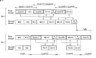
- FIG. 8 is a Gantt chart showing the method of execution for processes allocated to the first and the second threads, i.e. the i-th to the (i+2)-th unit HT process segments and the (i+1)-th to the (i+3)-th color conversion process segments. Note that here, the overhead when switching processes and the skew of the estimated load and actual load are ignored.
- the Gel shown at the upper level is a drawing showing the results when each process is executed with the first embodiment by repeating the allocation for each of the partial images of FIG. 3 .
- the alignment of the five process segments CC (i+1), C (i), M (i), Y (i), and K (i) at the upper left of FIG. 8 is the same as that of FIG. 7 .
- the Gc 1 shown at the lower level of FIG. 8 shows the execution results of each process with the comparison example.
- each unit HT process segment for the i-th partial image area LLs (i) and the color conversion process segment for the (i+1)-th partial image area LLs (i+1) end, next, each unit HT process segment for the (i+1)-th partial image area LLs (i+1) and the color conversion process segment for the (i+2)-th partial image area LLs (i+2) are allocated to each thread.
- the allocation procedure is as described in FIG. 5 to FIG. 7 .
- steps S 150 and S 180 of FIG. 3 immediately after the last of the unit HT process segments ends for the i-th partial image allocated previously, the next process is executed (see broken lines b 11 and b 12 of FIG. 8 ). For example, with the example shown in FIG. 8 , immediately after the unit HT process segment K (i) for the i-th partial image ends, the next color conversion process segment Cc (i+2) and the unit HT process segment M (i+1) are executed.
- the unit HT process segments of each ink color are executed with the first and second threads (see broken lines b 31 and b 32 of FIG. 8 ).
- the unit HT process segments C (i+1), M (i+1), Y (i+1), and K (i+1) of the (i+1)-th partial image are executed after the color conversion process segment Cc (i+1) of the (i+1)-th partial image is executed.
- the front-back positional constraints of the color conversion process segment and the unit HT process segments is indicated by the arrow that connects the color conversion process segment and each unit HT process segment in FIG. 8 .
- each unit HT process segment is allocated to the thread with the lowest total load of the unit HT process segments already allocated in order of decreasing load.
- the next partial area color conversion process segment is executed (see broken lines b 21 , b 22 , and b 23 of FIG. 8 ).
- the color conversion process segment Cc (i+1) of the (i+1)-th partial image is executed after the completion of the C (i) that is the last unit HT process segment of the unit HT process segments of the i-th partial image.
- the partial image subject to each process is indicated by “LLs (i)” etc.
- the second thread is not used during the time that the first thread is performing the color conversion process segment of each partial image.
- the unit HT process segments are being performed with the other thread while the color conversion is being performed.
- the completion time was faster for the first embodiment compared to the comparison example by a time of time Tdf 1 .
- the timing of the execution of processes allocated to each thread differs from that of the first embodiment.
- the other points are the same as the first embodiment.
- FIG. 9 is a Gantt chart showing the method of execution of processes allocated to the first and the second threads in the second embodiment, i.e. the i-th to the (i+2)-th unit HT process segments and the (i+1)-th to the (i+3)-th color conversion process segments.
- the notations are the same as those in FIG. 8 .
- the comparison example Gc 1 shown in the lower level of FIG. 9 is the same as that shown in the lower level of FIG. 8 .
- Cc (i+2), C (i+1), M (i+1), Y (i+1), and K (i+1), for example, are executed after waiting for the completion of all the process- segments Cc (i+1), C (i), M (i), Y (i), and K (i) allocated immediately prior at step 130 (see the broken lines b 11 and b 12 in FIG. 8 ).
- the allocation unit 99 a performs the next process segments Cc (i+2), C (i+1), M (i+1), Y (i+1), and K (i+1) (see step 130 in FIG. 3 ). Then, the allocation results are stored within the memory of the computer 90 .
- the processing time of the already completed process segments Cc (i), C (i ⁇ 1), M (i ⁇ 1), Y (i ⁇ 1), and K (i ⁇ 1) for the two prior partial images are used as the estimated load of each process used during allocation (see step S 10 of FIG. 5 ). Accordingly, in the second embodiment, the following processing time are stored in the load memory unit 105 , i.e. the processing time of the already completed process segments C (i), C (i ⁇ 1), M (i ⁇ 1), Y (i ⁇ 1), and K (i ⁇ 1) and the processing time of the process which has already been completed among the currently executing process segments Cc (i+1), C (i), M (i), Y (i), and K (i).
- this is the image data MID 2 of the partial image area LLs (i+1) generated by the color conversion process segment Cc (i+1) first, and the image data MID 2 of the partial image area LLs (i+2) generated partially by the currently executing color conversion process segment Cc (i+2).
- the completion time is faster by a time of Tdf 2 .
- the third embodiment while actually executing the color conversion process segment or the unit HT process segment, the next unit HT process segment to be executed is determined.
- the third embodiment is the same as the first embodiment except for the allocation and execution method of the color conversion process segments and the unit HT process segments to the threads.
- FIG. 10 is a flow chart showing the specific process flow of the color conversion process and the halftone process with the third embodiment.
- the color conversion process segments and the unit HT process segments are allocated and executed to the threads using the method shown in FIG. 10 .
- the color conversion process segments and the unit HT process segments that can be allocated to the threads are specified.
- the “color conversion process segments and the unit HT process segments that can be allocated to the threads” are the processes that satisfy the following conditions when all of the unit HT process segments up to the (i ⁇ 1)-th partial image area LLs (i ⁇ 1) and the color conversion process segments up to the i-th partial image area LLs (i) are completed. Specifically, these are the process segments that satisfy specified conditions among the unit HT process segments of the i-th to (i+1)-th partial images and the color conversion process segments of the (i+1)-th to the (i+2)-th partial image.
- the specified conditions are that either (1) the unit HT process segments using the dither method or (2) the unit HT process segments using the error diffusion method and the preceding partial images be completed at the start schedule time of the process segment for which allocation is currently being examined.
- the difference (error) between the density expression according to the presence or absence of dot formation and the density specified by tone values is distributed to other pixels that are not yet a subject pixel.
- the unit HT process segments using the error diffusion method in a state for which the unit HT process segmenting has not ended for the areas before the areas that are subject, the errors from the prior area have not been added to the tone values of the target area. Accordingly, in a state for which the unit HT process segmenting has not ended for the areas before the target area, the unit HT process segment cannot be executed. In contrast to this, the unit HT process segments executed using the dither method can be executed even in a state for which the unit HT process segmenting has not ended for the areas before the target areas.
- the unit HT process segments specified as “processes that can be allocated” are the processes that are executed using the dither method and also the unit HT process segments executed using the error diffusion method and which the unit HT process segments has been completed for the preceding partial images.
- FIG. 11 shows the method of allocating processes to the threads for the third embodiment.
- the halftone process is performed using the error diffusion method for cyan (C) and magenta (M), and performed using the dither method for yellow (Y) and black (K).
- the color conversion process segment Cc (i+1) of the (i+1)-th partial image has been completed already up to then.
- the specified process segments are the color conversion process segment Cc (i+2) of the (i+2)-th partial image, Y (i), K (i), Y (i+1), and K (i+1) which are unit HT process segments executed using the dither method, and M (i) and C (i) which are unit HT process segments executed using the error diffusion method and for which the process of the immediately prior partial image is completed.
- These are indicated as allocatable process segments Jp in FIG. 11 .
- the process with the biggest load is allocated to the thread for which the processes to be executed run out first.
- the estimated load of each process segment can be determined based on the execution results of the same type of process segment that was completed immediately prior.
- the estimated load of the color conversion process segment is the processing time of the color conversion process segment completed immediately prior.
- the estimated load of the unit HT process segment is the processing time of the unit HT process segment of the same color that was completed immediately prior.
- step S 135 for example as shown by arrow all of FIG. 11 , the color conversion process segment Cc (i+2) is allocated as the process starting from the time Pp 0 to the first thread.
- the sequence of the respective load sizes are shown at the left side of the allocatable process segments Jp.
- step S 140 the first thread which is in a standby state is set to an execution state. Then, at step S 155 , the color conversion process segment Cc (i+2) is executed at the first thread. After that, at step S 160 , the first thread is again set to a standby state. Note that the processes at steps S 140 and S 160 are the same as the first embodiment.
- step S 195 a determination is made of whether or not there is color conversion process segment or unit HT process segment that are not yet allocated to a thread. When there is process segment that has still not been allocated, the process returns to step S 125 . When all of the unit HT process segments have been allocated to either the first or the second thread, the processing ends.
- the color conversion process segments and the unit HT process segments that can be allocated to threads are specified.
- specified as the color conversion process segments and the unit HT process segments that can be allocated to the threads are the first Jp process segments shown in FIG. 11 that are process segments other than the color conversion process segment Cc (i+2) already allocated to a thread.
- the unit HT process segment M (i) is allocated to the second thread as a process starting from the time Pp 0 .
- steps S 170 to S 190 the unit HT process segment M (i) is executed at the second thread.
- the procedures for the steps S 170 to S 190 relating to the second thread are respectively the same as the procedures for the steps S 140 to S 195 relating to the first thread.
- the end time of each process is indicated as Pp 1 and Pp 2 in FIG. 11 .
- the unit HT process segments of up to the i-th partial image and the color conversion process segment Cc (i+1) of up to the (i+1)-th partial image are all completed.
- the unit HT process segments Y (i+2) and K (i+2) executed using the dither method and the color conversion process segment Cc (i+3) are newly added to the allocatable process segments Jp.
- allocation and execution of processes is performed up to the completion of all of the color conversion process segments and the unit HT process segments.
- the third embodiment it is possible to effectively utilize a plurality of threads to efficiently perform color conversion processing and halftone processing.
- the third embodiment when allocating and executing the unit HT process segments of the i-th partial images, simultaneously, part of the unit HT process segment of the (i+1)-th partial image and the color conversion process segment of up to the (i+2)-th partial images are subject to selection. Accordingly, by utilizing a large number of choices, it is possible to achieve a higher level of equalization of the load of each thread and to make processing more efficient.
- the process segments allocated at steps S 120 and S 130 were the halftone processes of each ink color of the subject raster lines LLs (i) and the color conversion process of the next raster lines LLs (i+1) of the subject raster lines LLs (i) (see step S 120 of FIG. 3 ).
- the processes selected as allocatable processes at step S 125 were the process segmenmts among the unit HT process segments of the i-th to the (i+1)-th partial images that satisfy specified conditions and the color conversion process segments of the (i+1)-th to the (i+2)-th partial images.
- the process segments subject to allocation may include the following processes when the unit HT process segments up to the (i ⁇ 1)-th (i is an integer of 2 or greater) partial image and the color conversion process segments up to the i-th partial image are all completed.
- the group of process segments subject to allocation may include process segments that are the second-type process segments relating to the i-th partial images but that have not yet been allocated to a processing unit and the first-type process segments relating to the (i+1)-th to the (i+p)-th (p is a positive integer) partial images that have not yet been allocated to a processing unit.
- the first-type process segments must be process segments that are completed before the second-type process segments relating to the same partial image.
- p be 4 or less, and more preferable that it be 3 or less. Then, it is even more desirable that p be 2 or less. If these aspects are used, it is possible to reduce the capacity of the memory unit for holding the second partial image data generated after the first-type process segment.
- the process segments subject to allocation may include the following process segments when the unit HT process segments up to the (i ⁇ 1)-th partial image and the color conversion process segments up to the i-th partial image are all completed.
- these are restricted process segments relating to the (i+1)-th to the (i+q)-th (q is a positive integer) partial images, that are not yet allocated to a processing unit, and that are restricted processes for which the same type of restricted process relating to the immediately prior partial image is completed at the scheduled time for starting the execution of processing of the subject processing group.
- the restricted process is a process that is executable only after the same type of restricted process relating to the immediately prior partial image is completed.
- q be 4 or less, and more preferable that it be 3 or less. Then, it is even more preferable that q be 2 or less. If these aspects are used, it is possible to decrease the capacity of the memory unit for holding the difference (error) generated after the unit HT process segmenting using the error diffusion method as the second-type process segment.
- one CPU of the computer executes unit HT process segments with a plurality of threads using hyper threading.
- the unit HT process segments can also be distributed to a plurality of CPUs and executed.
- the threads were fixed at two threads.
- the image processing device which is one embodiment of the present invention, may use an aspect having a plurality of operating modes such as an operating mode having one thread, an operating mode having two threads, and an operating mode having three threads.
- the image processing device which is one embodiment of the present invention, may use an aspect having a plurality of operating modes such as an operating mode having one thread, an operating mode having two threads, and an operating mode having three threads.
- the thread or CPU it is possible to perform load allocation and execution sequence determination using the same procedures as each of the embodiments noted above.
- there is one processing unit it is possible to have an aspect that executes each of the unit process segments on that processing unit following the pre-determined sequence.
- the processing time of each process segment for the area for which processing was performed immediately prior was used as the corresponding process segment load.
- process segment load estimation based on other values. For example, it is possible to use the dot generation volume or dot generation probability of each ink color within the area LLs (i ⁇ 1) for which halftone processing was performed immediately prior as the load of each unit HT process segment for the area LLs (i) for which the halftone processing is performed next.
- the estimated load of the color conversion process segment be a specified fixed value.
- allocation to threads is performed from the items for which the dot generation volume or dot generation probability is higher for the immediately prior area LLs (i ⁇ 1) (see FIG.7 and FIG. 11 ).
- the load uniformly. For example, it is possible to set 1 for the load of the unit HT process segments for which the halftone process is performed using the dither method, to set 3 for the load for the unit HT process segments for which the halftone process is performed using the error diffusion method, and to set 5 for the load of the color conversion process segment. Furthermore, it is also possible to set the load based on the kind of the halftone processing method, the processing time, dot generation volume and/or generation probability described above.
- the load of the unit HT process segment for which the halftone process is performed using the dither method is set to 1 ⁇ “dot generation probability” and to set the load of the unit HT process segment for which the halftone process is performed using the error diffusion method to 3 ⁇ “dot generation probability.”
- the color conversion process segment load be a fixed value.
- the estimate of the unit process segment load be determined considering the execution results of each unit process executed immediately prior.
- each process is executed in the allocation sequence for the allocation to the threads.
- scheduling that determines the execution sequence within a plurality of process segments allocated as one group simultaneously (See Step S 120 in FIG. 3 ), separate from the allocation of processes to each thread.
- For allocation of processes to each processing unit if allocation of process segments with a relatively small load is executed after the process segments with a relatively big load, and one process segment at a time is allocated to the processing unit with the smaller total load allocated up to that point, it is possible to perform allocation with little variation of load between the processing units.
- the halftone processing is performed using units of each dot type for each ink color.
- the unit HT process segments were halftone processes for each ink color, but for this aspect, it is possible to have the unit HT process segment be halftone processing in units of each dot type for each ink color.
- inks four types of ink, cyan (C), magenta (M), yellow (Y), and black (K), were used as inks.
- chromatic color inks other than these such as read (R), violet (V) etc., or chromatic color inks with different thickness such as light cyan (LC), light magenta (LM), dark yellow (DY) etc.
- light cyan is ink that is the same hue as cyan but of a lighter color than cyan.
- Light magenta is ink of the same hue as magenta but of a lighter color than magenta.
- dark yellow is ink of the same hue as yellow but of a darker color than yellow.
- ink it is possible to use achromatic colors of different density, including black (K1), light black (K2), and light light black (K3). Furthermore, it is possible to use clear ink.
- ink it is possible to use various colored inks, and for the halftone process to include unit HT process segments for the various ink colors.
- the types of ink colors can be 2 or more
- the second partial image data representing a partial image, which is generated by performing the first-type process segment on the first partial image can be 2 or more types of partial image data.
- the second partial image data is preferably 3 types or more.
- the first-type process segment can be a process that is executed on the first partial image data for representing a partial image, and that generates mutually different M types (M is an integer of 2 or greater) of second partial image data.
- the second-type process segment can be an image process executed respectively on the aforementioned M types of second partial image data.
- the M types of second partial image data can be image data represented by mutually differing color contrasting densities.
- a computer program for realizing these functions are provided in a format recorded on a computer readable recording medium such as a floppy disk, a CD-ROM, etc.
- the host computer reads the computer program from that recording medium and transfers it to either an internal storage device or an external storage device. Alternatively, it is also possible to supply the computer program to the host computer from a program supply device via a communication path.
- the computer program stored in the internal storage device is executed by the microprocessor of the host computer. It is also possible to have the host computer directly execute the computer program recorded in the recording medium.
- a computer is a concept that includes a hardware device and an operating system, and means a hardware device that operates under the control of the operating system.
- the computer program executes the functions of each part described above on this kind of computer. Note that part of the functions described above may also be realized not by a driver or an application program but rather by the operating system.
- a “computer readable recording medium” is not limited to a portable type recording medium such as a flexible disk or a CD-ROM, but also includes internal storage devices within the computer such as various types of RAM or ROM or the like, and external storage devices fixed to a computer such as a hard disk.
- the Program product may be realized as many aspects. For example:
Applications Claiming Priority (2)
| Application Number | Priority Date | Filing Date | Title |
|---|---|---|---|
| JP2004245085A JP4501593B2 (ja) | 2004-08-25 | 2004-08-25 | 画像処理を並列処理で実行する際の負荷の割り付け |
| JP2004-245085 | 2004-08-25 |
Publications (2)
| Publication Number | Publication Date |
|---|---|
| US20060050955A1 US20060050955A1 (en) | 2006-03-09 |
| US7460285B2 true US7460285B2 (en) | 2008-12-02 |
Family
ID=35996265
Family Applications (1)
| Application Number | Title | Priority Date | Filing Date |
|---|---|---|---|
| US11/212,430 Expired - Fee Related US7460285B2 (en) | 2004-08-25 | 2005-08-24 | Load allocation when executing image processing using parallel processing |
Country Status (2)
| Country | Link |
|---|---|
| US (1) | US7460285B2 (ja) |
| JP (1) | JP4501593B2 (ja) |
Cited By (3)
| Publication number | Priority date | Publication date | Assignee | Title |
|---|---|---|---|---|
| US20060132874A1 (en) * | 2004-12-20 | 2006-06-22 | Canon Kabushiki Kaisha | Apparatus and method for processing data |
| US20090284773A1 (en) * | 2008-05-15 | 2009-11-19 | Canon Kabushiki Kaisha | Image processing method, image processing apparatus, and control method thereof |
| US8705108B1 (en) * | 2012-11-06 | 2014-04-22 | Fuji Xerox Co., Ltd. | Non-transitory computer readable medium storing program for executing print image processing system |
Families Citing this family (4)
| Publication number | Priority date | Publication date | Assignee | Title |
|---|---|---|---|---|
| US20080199085A1 (en) * | 2007-02-19 | 2008-08-21 | Seiko Epson Corporation | Category Classification Apparatus, Category Classification Method, and Storage Medium Storing a Program |
| US20130055072A1 (en) * | 2011-08-24 | 2013-02-28 | Robert Douglas Arnold | Multi-Threaded Graphical Display System |
| JP6834402B2 (ja) * | 2016-11-24 | 2021-02-24 | 株式会社リコー | 情報処理装置、情報処理システム、情報処理方法、及びプログラム |
| US10497340B2 (en) | 2017-04-10 | 2019-12-03 | Intel Corporation | Beam scanning image processing within an improved graphics processor microarchitecture |
Citations (10)
| Publication number | Priority date | Publication date | Assignee | Title |
|---|---|---|---|---|
| US5765146A (en) * | 1993-11-04 | 1998-06-09 | International Business Machines Corporation | Method of performing a parallel relational database query in a multiprocessor environment |
| US5881283A (en) * | 1995-04-13 | 1999-03-09 | Hitachi, Ltd. | Job scheduling analysis method and system using historical job execution data |
| US5930010A (en) * | 1996-01-31 | 1999-07-27 | Lexmark International, Inc. | Method and apparatus for color halftoning using different halftoning techniques for halftoning different dot planes |
| JP2000293674A (ja) | 1999-04-12 | 2000-10-20 | Seiko Epson Corp | 画像処理方法、印刷装置、画像処理システムおよび記録媒体 |
| US6532016B1 (en) * | 1997-10-23 | 2003-03-11 | Texas Instruments Incorporated | Method of processing print data using parallel raster image processing |
| US20030137698A1 (en) * | 2002-01-18 | 2003-07-24 | Pritchard Thomas B. | System for improving the speed of data processing |
| US20040008382A1 (en) * | 2002-07-09 | 2004-01-15 | Barbalet Thomas Samuel | System and method for error diffusion screening with parallel processing |
| US20040207879A1 (en) * | 2003-04-16 | 2004-10-21 | Bailey James Ray | Systems and methods for error diffusion |
| US20050141017A1 (en) * | 2002-02-26 | 2005-06-30 | Eisei Matsumura | Printer controller |
| US20050260021A1 (en) * | 2002-04-27 | 2005-11-24 | Lluis Abello | Print engines |
Family Cites Families (17)
| Publication number | Priority date | Publication date | Assignee | Title |
|---|---|---|---|---|
| JPS61125275A (ja) * | 1984-11-20 | 1986-06-12 | Mitsubishi Electric Corp | 画像信号処理装置 |
| JPH01312672A (ja) * | 1988-06-13 | 1989-12-18 | Nippon Telegr & Teleph Corp <Ntt> | 画像処理装置 |
| JP3169219B2 (ja) * | 1990-08-31 | 2001-05-21 | 株式会社リコー | カラー画像形成装置 |
| JPH05242051A (ja) * | 1992-02-28 | 1993-09-21 | Nec Corp | タスクスケジューリング方式 |
| JPH0612392A (ja) * | 1992-03-19 | 1994-01-21 | Fujitsu Ltd | 計算機資源分散方法及びシステム |
| JPH06274608A (ja) * | 1993-03-23 | 1994-09-30 | Seiko Epson Corp | マルチプロセッサ画像処理装置 |
| JPH07244646A (ja) * | 1994-03-03 | 1995-09-19 | Hitachi Ltd | マルチcpuシステム用マイクロコンピュータ、及びこれを用いたシステム並びにネットワーク |
| JPH0844678A (ja) * | 1994-07-29 | 1996-02-16 | Canon Inc | 画像処理装置及びシステム |
| JPH08307720A (ja) * | 1995-05-12 | 1996-11-22 | Seiko Epson Corp | カラー画像の階調数変換方式及び方法 |
| JPH10143380A (ja) * | 1996-11-07 | 1998-05-29 | Hitachi Ltd | マルチプロセッサシステム |
| JPH11252357A (ja) * | 1998-02-27 | 1999-09-17 | Sharp Corp | 画像処理装置 |
| JP3800835B2 (ja) * | 1998-12-10 | 2006-07-26 | 富士ゼロックス株式会社 | 画像処理装置 |
| JP2001075934A (ja) * | 1999-09-07 | 2001-03-23 | Nec Eng Ltd | 負荷分散処理システム及び方法 |
| JP2003150947A (ja) * | 2001-11-16 | 2003-05-23 | Minolta Co Ltd | 非線形処理用プロセッサ |
| JP2004135317A (ja) * | 2002-09-18 | 2004-04-30 | Fuji Xerox Co Ltd | カラー画像処理装置およびカラー画像処理方法 |
| US6971103B2 (en) * | 2002-10-15 | 2005-11-29 | Sandbridge Technologies, Inc. | Inter-thread communications using shared interrupt register |
| JP2005094126A (ja) * | 2003-09-12 | 2005-04-07 | Canon Inc | 画像処理装置および画像処理方法およびコンピュータで実行可能な画像処理プログラム |
-
2004
- 2004-08-25 JP JP2004245085A patent/JP4501593B2/ja not_active Expired - Fee Related
-
2005
- 2005-08-24 US US11/212,430 patent/US7460285B2/en not_active Expired - Fee Related
Patent Citations (10)
| Publication number | Priority date | Publication date | Assignee | Title |
|---|---|---|---|---|
| US5765146A (en) * | 1993-11-04 | 1998-06-09 | International Business Machines Corporation | Method of performing a parallel relational database query in a multiprocessor environment |
| US5881283A (en) * | 1995-04-13 | 1999-03-09 | Hitachi, Ltd. | Job scheduling analysis method and system using historical job execution data |
| US5930010A (en) * | 1996-01-31 | 1999-07-27 | Lexmark International, Inc. | Method and apparatus for color halftoning using different halftoning techniques for halftoning different dot planes |
| US6532016B1 (en) * | 1997-10-23 | 2003-03-11 | Texas Instruments Incorporated | Method of processing print data using parallel raster image processing |
| JP2000293674A (ja) | 1999-04-12 | 2000-10-20 | Seiko Epson Corp | 画像処理方法、印刷装置、画像処理システムおよび記録媒体 |
| US20030137698A1 (en) * | 2002-01-18 | 2003-07-24 | Pritchard Thomas B. | System for improving the speed of data processing |
| US20050141017A1 (en) * | 2002-02-26 | 2005-06-30 | Eisei Matsumura | Printer controller |
| US20050260021A1 (en) * | 2002-04-27 | 2005-11-24 | Lluis Abello | Print engines |
| US20040008382A1 (en) * | 2002-07-09 | 2004-01-15 | Barbalet Thomas Samuel | System and method for error diffusion screening with parallel processing |
| US20040207879A1 (en) * | 2003-04-16 | 2004-10-21 | Bailey James Ray | Systems and methods for error diffusion |
Non-Patent Citations (2)
| Title |
|---|
| Abstract of Japanese Patent Publication No. 2000-293674, Pub. Date: Oct. 20, 2000, Patent Abstracts of Japan. |
| Performance Modeling of Operating Systems Using Object-Oriented Simulation-A Practical Introduction. Garrido, Jose M. Pring (c)2000 Kluwer Academic/Plenum Publishers. First Edition. pp. 85-109. * |
Cited By (6)
| Publication number | Priority date | Publication date | Assignee | Title |
|---|---|---|---|---|
| US20060132874A1 (en) * | 2004-12-20 | 2006-06-22 | Canon Kabushiki Kaisha | Apparatus and method for processing data |
| US8022957B2 (en) * | 2004-12-20 | 2011-09-20 | Canon Kabushiki Kaisha | Apparatus and method for processing data |
| US8243084B2 (en) * | 2004-12-20 | 2012-08-14 | Canon Kabushiki Kaisha | Apparatus and method for processing data |
| US20090284773A1 (en) * | 2008-05-15 | 2009-11-19 | Canon Kabushiki Kaisha | Image processing method, image processing apparatus, and control method thereof |
| US8253977B2 (en) * | 2008-05-15 | 2012-08-28 | Canon Kabushiki Kaisha | Controlling share of processing by each processor based on tendency of compositing pixel information in an image area |
| US8705108B1 (en) * | 2012-11-06 | 2014-04-22 | Fuji Xerox Co., Ltd. | Non-transitory computer readable medium storing program for executing print image processing system |
Also Published As
| Publication number | Publication date |
|---|---|
| JP2006065460A (ja) | 2006-03-09 |
| US20060050955A1 (en) | 2006-03-09 |
| JP4501593B2 (ja) | 2010-07-14 |
Similar Documents
| Publication | Publication Date | Title |
|---|---|---|
| US7466465B2 (en) | Load allocation when executing image processing using parallel processing | |
| US7460285B2 (en) | Load allocation when executing image processing using parallel processing | |
| US6327050B1 (en) | Printing method and apparatus having multiple raster image processors | |
| US10068518B2 (en) | Method, apparatus and system for dithering an image | |
| US8098402B2 (en) | Document targeting systems and methods | |
| US6429950B1 (en) | Method and apparatus for applying object characterization pixel tags to image data in a digital imaging device | |
| US7436559B2 (en) | Load assignment in image processing by parallel processing | |
| JP2007087137A (ja) | 印刷制御装置、画像形成方法および記憶媒体 | |
| US20130128307A1 (en) | Printing device and printing method of printing device | |
| JP2005250565A (ja) | 画像処理を並列処理で実行する際の負荷の割り付け | |
| US9883078B2 (en) | Systems and methods for efficient halftone where different dithering matrices are combined | |
| JP4400739B2 (ja) | 色変換方法、色変換装置、色変換プログラム、印刷制御方法、印刷制御装置および印刷制御プログラム | |
| JP5471696B2 (ja) | 画像処理装置、及び画像処理プログラム | |
| US11205242B2 (en) | Memory error recovery for complex page RIP | |
| JP2005259042A (ja) | 画像処理方法および画像処理プログラム | |
| JP2013078873A (ja) | 画像処理装置および画像処理方法 | |
| JPH1178126A (ja) | カラープリント装置 | |
| JP2007306445A (ja) | 画像データ変換装置 | |
| JP3686490B2 (ja) | プリンタドライバのアーキテクチャのための可変2値化処理を使用するシステムおよび方法 | |
| JP5899860B2 (ja) | 印刷装置および印刷装置の印刷方法 | |
| US7213899B2 (en) | Memory use and management method and system for a multi-pass printer | |
| JP2003274110A (ja) | 画像処理システム、画像処理方法および画像処理プログラム | |
| JP2006021412A (ja) | 画像処理装置および画像処理方法 | |
| JP4508952B2 (ja) | 画像処理方法及び画像処理装置 | |
| US20060119875A1 (en) | Print apparatus and print method |
Legal Events
| Date | Code | Title | Description |
|---|---|---|---|
| AS | Assignment |
Owner name: SEIKO EPSON CORPORATION, JAPAN Free format text: ASSIGNMENT OF ASSIGNORS INTEREST;ASSIGNORS:YAMAZAKI, SATOSHI;KAKUTANI, TOSHIAKI;TAKATA, TERUYUKI;AND OTHERS;REEL/FRAME:017237/0229;SIGNING DATES FROM 20051021 TO 20051026 |
|
| FEPP | Fee payment procedure |
Free format text: PAYOR NUMBER ASSIGNED (ORIGINAL EVENT CODE: ASPN); ENTITY STATUS OF PATENT OWNER: LARGE ENTITY |
|
| REMI | Maintenance fee reminder mailed | ||
| LAPS | Lapse for failure to pay maintenance fees | ||
| STCH | Information on status: patent discontinuation |
Free format text: PATENT EXPIRED DUE TO NONPAYMENT OF MAINTENANCE FEES UNDER 37 CFR 1.362 |
|
| FP | Lapsed due to failure to pay maintenance fee |
Effective date: 20121202 |