US7410327B2 - Arctic platform - Google Patents
Arctic platform Download PDFInfo
- Publication number
- US7410327B2 US7410327B2 US11/704,614 US70461407A US7410327B2 US 7410327 B2 US7410327 B2 US 7410327B2 US 70461407 A US70461407 A US 70461407A US 7410327 B2 US7410327 B2 US 7410327B2
- Authority
- US
- United States
- Prior art keywords
- platform
- support
- platform section
- sides
- fence
- Prior art date
- Legal status (The legal status is an assumption and is not a legal conclusion. Google has not performed a legal analysis and makes no representation as to the accuracy of the status listed.)
- Expired - Lifetime
Links
- 238000005553 drilling Methods 0.000 claims abstract description 94
- 238000000034 method Methods 0.000 claims abstract description 54
- 238000004519 manufacturing process Methods 0.000 abstract description 26
- 238000007789 sealing Methods 0.000 abstract description 20
- 238000003860 storage Methods 0.000 abstract description 15
- 238000009434 installation Methods 0.000 abstract description 10
- 230000002708 enhancing effect Effects 0.000 abstract 1
- 239000012530 fluid Substances 0.000 description 69
- XLYOFNOQVPJJNP-UHFFFAOYSA-N water Substances O XLYOFNOQVPJJNP-UHFFFAOYSA-N 0.000 description 19
- 238000004891 communication Methods 0.000 description 17
- 239000002002 slurry Substances 0.000 description 12
- 238000012546 transfer Methods 0.000 description 12
- 239000007788 liquid Substances 0.000 description 11
- 238000010438 heat treatment Methods 0.000 description 9
- 230000008569 process Effects 0.000 description 8
- 238000007710 freezing Methods 0.000 description 7
- 230000008014 freezing Effects 0.000 description 7
- 230000014759 maintenance of location Effects 0.000 description 7
- 229910052751 metal Inorganic materials 0.000 description 7
- 239000002184 metal Substances 0.000 description 6
- 239000000203 mixture Substances 0.000 description 6
- 239000002699 waste material Substances 0.000 description 6
- 229920005830 Polyurethane Foam Polymers 0.000 description 5
- 229910052782 aluminium Inorganic materials 0.000 description 5
- XAGFODPZIPBFFR-UHFFFAOYSA-N aluminium Chemical compound [Al] XAGFODPZIPBFFR-UHFFFAOYSA-N 0.000 description 5
- 230000007613 environmental effect Effects 0.000 description 5
- 239000011496 polyurethane foam Substances 0.000 description 5
- 239000004576 sand Substances 0.000 description 5
- LYCAIKOWRPUZTN-UHFFFAOYSA-N Ethylene glycol Chemical compound OCCO LYCAIKOWRPUZTN-UHFFFAOYSA-N 0.000 description 4
- 239000006260 foam Substances 0.000 description 4
- 238000009413 insulation Methods 0.000 description 4
- 230000035508 accumulation Effects 0.000 description 3
- 238000009825 accumulation Methods 0.000 description 3
- 230000000712 assembly Effects 0.000 description 3
- 238000000429 assembly Methods 0.000 description 3
- 230000033228 biological regulation Effects 0.000 description 3
- 230000000295 complement effect Effects 0.000 description 3
- 238000010276 construction Methods 0.000 description 3
- 239000013505 freshwater Substances 0.000 description 3
- 240000004282 Grewia occidentalis Species 0.000 description 2
- 229910000831 Steel Inorganic materials 0.000 description 2
- 230000003466 anti-cipated effect Effects 0.000 description 2
- -1 antifreeze Substances 0.000 description 2
- 230000008901 benefit Effects 0.000 description 2
- 230000015572 biosynthetic process Effects 0.000 description 2
- 239000002131 composite material Substances 0.000 description 2
- 238000001816 cooling Methods 0.000 description 2
- 238000005520 cutting process Methods 0.000 description 2
- 238000011161 development Methods 0.000 description 2
- 238000009826 distribution Methods 0.000 description 2
- 230000000694 effects Effects 0.000 description 2
- 238000004880 explosion Methods 0.000 description 2
- 239000000835 fiber Substances 0.000 description 2
- 150000004677 hydrates Chemical class 0.000 description 2
- WGCNASOHLSPBMP-UHFFFAOYSA-N hydroxyacetaldehyde Natural products OCC=O WGCNASOHLSPBMP-UHFFFAOYSA-N 0.000 description 2
- 239000000314 lubricant Substances 0.000 description 2
- 238000012423 maintenance Methods 0.000 description 2
- 230000002265 prevention Effects 0.000 description 2
- 230000000452 restraining effect Effects 0.000 description 2
- 238000005096 rolling process Methods 0.000 description 2
- 239000010959 steel Substances 0.000 description 2
- 238000003466 welding Methods 0.000 description 2
- 229910000838 Al alloy Inorganic materials 0.000 description 1
- 229920004943 Delrin® Polymers 0.000 description 1
- 230000001154 acute effect Effects 0.000 description 1
- 238000007792 addition Methods 0.000 description 1
- 238000004458 analytical method Methods 0.000 description 1
- 230000002528 anti-freeze Effects 0.000 description 1
- 230000003190 augmentative effect Effects 0.000 description 1
- 230000009286 beneficial effect Effects 0.000 description 1
- 235000012206 bottled water Nutrition 0.000 description 1
- 238000009395 breeding Methods 0.000 description 1
- 230000001488 breeding effect Effects 0.000 description 1
- 239000003638 chemical reducing agent Substances 0.000 description 1
- 239000004020 conductor Substances 0.000 description 1
- 239000012809 cooling fluid Substances 0.000 description 1
- 238000012937 correction Methods 0.000 description 1
- 238000013461 design Methods 0.000 description 1
- 239000002283 diesel fuel Substances 0.000 description 1
- 239000003651 drinking water Substances 0.000 description 1
- 229920001971 elastomer Polymers 0.000 description 1
- 238000005485 electric heating Methods 0.000 description 1
- 238000009429 electrical wiring Methods 0.000 description 1
- 238000005516 engineering process Methods 0.000 description 1
- 239000002360 explosive Substances 0.000 description 1
- 239000000446 fuel Substances 0.000 description 1
- 239000004519 grease Substances 0.000 description 1
- 229930195733 hydrocarbon Natural products 0.000 description 1
- 150000002430 hydrocarbons Chemical class 0.000 description 1
- 239000012774 insulation material Substances 0.000 description 1
- 239000000463 material Substances 0.000 description 1
- 239000007769 metal material Substances 0.000 description 1
- 238000013508 migration Methods 0.000 description 1
- 230000005012 migration Effects 0.000 description 1
- 238000012986 modification Methods 0.000 description 1
- 230000004048 modification Effects 0.000 description 1
- 239000003208 petroleum Substances 0.000 description 1
- 229920003023 plastic Polymers 0.000 description 1
- 239000004033 plastic Substances 0.000 description 1
- 230000001105 regulatory effect Effects 0.000 description 1
- 238000005067 remediation Methods 0.000 description 1
- 239000000565 sealant Substances 0.000 description 1
- 239000003566 sealing material Substances 0.000 description 1
- 230000001932 seasonal effect Effects 0.000 description 1
- 238000005245 sintering Methods 0.000 description 1
- 238000005507 spraying Methods 0.000 description 1
- 210000000352 storage cell Anatomy 0.000 description 1
- 239000002352 surface water Substances 0.000 description 1
- 238000012360 testing method Methods 0.000 description 1
- 229920000785 ultra high molecular weight polyethylene Polymers 0.000 description 1
Images


Classifications
-
- E—FIXED CONSTRUCTIONS
- E02—HYDRAULIC ENGINEERING; FOUNDATIONS; SOIL SHIFTING
- E02D—FOUNDATIONS; EXCAVATIONS; EMBANKMENTS; UNDERGROUND OR UNDERWATER STRUCTURES
- E02D27/00—Foundations as substructures
- E02D27/32—Foundations for special purposes
- E02D27/35—Foundations formed in frozen ground, e.g. in permafrost soil
-
- E—FIXED CONSTRUCTIONS
- E02—HYDRAULIC ENGINEERING; FOUNDATIONS; SOIL SHIFTING
- E02D—FOUNDATIONS; EXCAVATIONS; EMBANKMENTS; UNDERGROUND OR UNDERWATER STRUCTURES
- E02D27/00—Foundations as substructures
- E02D27/10—Deep foundations
- E02D27/12—Pile foundations
-
- E—FIXED CONSTRUCTIONS
- E02—HYDRAULIC ENGINEERING; FOUNDATIONS; SOIL SHIFTING
- E02D—FOUNDATIONS; EXCAVATIONS; EMBANKMENTS; UNDERGROUND OR UNDERWATER STRUCTURES
- E02D3/00—Improving or preserving soil or rock, e.g. preserving permafrost soil
- E02D3/11—Improving or preserving soil or rock, e.g. preserving permafrost soil by thermal, electrical or electro-chemical means
- E02D3/115—Improving or preserving soil or rock, e.g. preserving permafrost soil by thermal, electrical or electro-chemical means by freezing
-
- E—FIXED CONSTRUCTIONS
- E02—HYDRAULIC ENGINEERING; FOUNDATIONS; SOIL SHIFTING
- E02B—HYDRAULIC ENGINEERING
- E02B17/00—Artificial islands mounted on piles or like supports, e.g. platforms on raisable legs or offshore constructions; Construction methods therefor
- E02B2017/0052—Removal or dismantling of offshore structures from their offshore location
Definitions
- the present invention relates generally to the field of oil and gas drilling and production.
- the invention comprises a system and method of drilling oil and gas wells in arctic, inaccessible or environmentally sensitive locations without significantly disturbing an associated ground surface.
- Drilling locations are accessed by a variety of means, for example, by roadway, waterway or another suitable access route. In particularly remote locations, access to a drilling site is sometimes achieved via airlift, either by helicopter, fixed wing aircraft, or both.
- oil and gas reserves may be disposed in locales having accumulations of surface and near-surface water, such as swamps, tidal flats, jungles, stranded lakes, tundra, muskegs, and permafrost regions.
- swamps, muskegs, and tidal flats the ground is generally too soft to support trucks and other heavy equipment, and the water is generally too shallow for traditional equipment to be floated in.
- tundra and permafrost regions heavy equipment can be supported only during the winter months.
- Land drilling in arctic regions is currently performed on ice pads, the dimensions of which are about 500 feet on a side; typically, the ice pads comprise 6-inch thick sheets of ice.
- the rig itself is built on a thicker ice pad, for example, a 6- to 12-inch thick pad.
- a reserve pit is typically constructed with about a two-foot thickness of ice, plus an ice berm, which provides at least two feet of freeboard space above the pit's contents.
- These reserve pits sometimes referred to as ice-bermed drilling waste storage cells, typically have a volume capacity of about 45,000 cubic feet, suitable for accumulating and storing about 15,000 cubic feet of cuttings and effluent.
- an arctic drilling location sometimes includes an airstrip, which is essentially a broad, extended ice road formed as described above.
- Ice roads can run from a few miles to tens of miles or longer, depending upon the proximity or remoteness of the existing infrastructure.
- the fresh water needed for the ice to construct the roads and pads is usually obtained from lakes and ponds that are generally numerous in such regions.
- the construction of an ice road typically requires around 1,000,000 gallons of water per linear mile. Over the course of a winter season, another 200,000 gallons or so per mile are required to maintain the ice road. Therefore, for a ten-mile ice road, a total of 2,000,000 gallons of water would have to be picked up from nearby lakes and sprayed on the selected route to maintain the structural integrity of the ice road.
- An airstrip requires about 2,000,000 gallons of water per mile to construct, and a single drill pad requires about 1,700,000 gallons. For drilling operations on a typical 30-day well, an additional 20,000 gallons per day are required, for a total of about 600,000 gallons for the well. A 75-man camp requires another 5,000 gallons per day, or 150,000 gallons per month, to support. Sometimes, there are two to four wells drilled from each pad, frequently with a geological side-track in each well, and thus even more water is required to maintain the site.
- Drilling operations typically commence around the beginning of February, and last until the middle of April, at which time all equipment and waste-pit contents must be removed before the ice pads and roads melt.
- the tundra is closed to all traffic from May 15 to July 1 due to nesting birds. If the breakup is late, then drilling prospects can be fully tested before demobilizing the rig. Otherwise, the entire infrastructure has to be removed, and then rebuilt the following season.
- a method of constructing a drilling or production platform including: drilling a post hole into a ground surface; inserting a support post into said post hole, wherein said support post has an adjustable shoulder member; adding a fluid slurry to said post hole to freeze said support post within an interior region of said post hole; disposing a modular platform section on top of said adjustable shoulder member to establish a platform deck surface; and adjusting said adjustable shoulder member so that said platform deck surface is disposed substantially level.
- a method of constructing a drilling or production platform including: drilling or hammering a support post into a ground surface, wherein said support post further comprises an adjustable shoulder member; disposing a modular platform section on top of said adjustable shoulder member to establish a platform deck surface; and adjusting said adjustable shoulder member so that said platform deck surface is disposed substantially level.
- a method of constructing a platform suitable for drilling and producing oil, gas and hydrate reserves including: disposing a platform section atop a plurality of support posts; disposing two substantially parallel support beam sections between two of said support posts; and disposing a deck section atop said two substantially parallel support beams to provide a bridging support means between said two substantially parallel beams.
- a method of constructing a drilling or production platform including: providing a first platform section supported by support posts, wherein each of said support posts are disposed proximate to the corners of said first platform section; providing a second platform section, wherein said second platform section further comprises a hooking member that hooks onto a first side of said first platform section; providing a plurality of support posts to support a side of said second platform section disposed opposite said first side of said second platform section; and providing a third platform section, wherein said third platform section further comprises a hooking member that hooks said second platform section.
- a method of assembling a plurality of interlocking modular platform sections useful for supporting drilling equipment on a deck surface including: disposing a first modular platform section and a second modular platform section atop a plurality of platform support posts; disposing a hook and hook receiving member proximate an interface formed between said first platform section and said second platform section, wherein said hook is disposed along a side portion of said first platform section, and said hook receiving member is disposed on a side portion of said second platform section, and thereby.
- a method of communicating utilities between a deck section and a platform section of a drilling or production platform including: disposing a deck section atop a platform section; disposing one or more holes in a top surface of said deck section to permit utility communication between an interior region of said deck section and a deck surface disposed atop said deck section; and disposing one or more holes between a lower surface of said deck section and an upper surface of said platform section.
- a method of heating a drilling or production platform support post including: disposing a fluid conduit through a body portion of said support post; disposing a hollow fluid transfer member around or near an outer surface of said support post, wherein said fluid conduit disposed in a body portion of said support post is in fluid communication with said hollow fluid transfer member; and drawing a cooling or warm fluid into said fluid conduit and passing said fluid through said hollow fluid transfer member.
- a method of removing a drilling or production platform support post including: disposing a fluid conduit through a body portion of said support post; disposing a hollow fluid transfer member around or near an outer surface of said support post, wherein said fluid conduit is disposed in fluid communication with said hollow fluid transfer member; drawing a warm fluid into said fluid conduit and passing said fluid through said hollow fluid transfer member to heat the surrounding ground; and applying a pulling force to said support post to pull said support post from the ground.
- a method of removing a drilling or production platform support post including: disposing a fluid conduit through a body portion of said support post; disposing a hollow fluid transfer member around or near an outer surface of said support post, wherein said fluid conduit is in fluid communication with said hollow fluid transfer member; disposing a vent between said fluid conduit and a surrounding ground surface using jets or ports; drawing a fluid or gas into said fluid conduit and passing said fluid through said hollow fluid transfer member, through said vent and out to the surrounding ground surface; and applying a pulling force to said support post to pull said support post from the ground.
- a method of adjusting the height of a modular drilling or production platform section including: disposing a modular platform section atop an adjustable shoulder nut disposed on a support post, wherein a top portion of said support post further comprises a lift receiving means; disposing a lifting means proximate to said lift receiving means, and then mutually engaging said lifting means and said lift receiving means; lifting said modular platform section off of said adjustable shoulder nut and then supporting said modular platform section using a support means; raising said adjustable shoulder nut; and replacing said modular platform section atop said adjustable shoulder nut using said support means.
- a method of sealing an intersection formed between a plurality of interlocked platform modules including: disposing four interlocked platform modules so that a four-way intersection is formed therebetween; disposing a sealing member over said four-way intersection, wherein said sealing member comprises a body member and a plurality of leg members; and augmenting the seal using a deformable sealing material.
- FIG. 1 is a modular drilling or production platform according to the invention.
- FIG. 2 is a section of a well bore included in the drilling or production platform shown in FIG. 1 , taken at a right angle along a length of the platform.
- FIG. 3 is a section of a well bore included in the drilling or production platform shown in FIG. 1 , taken along a centerline of the platform.
- FIG. 4 is a sectional view of a surface tundra region in which a plurality of post holes has been drilled.
- FIG. 5 is the sectional view of FIG. 4 , further comprising a plurality of support posts disposed in the post holes.
- FIG. 6 is the sectional view of FIG. 5 , further comprising a plurality of support posts having adjustable shoulders.
- FIG. 7 is the sectional view of FIG. 6 , further comprising a group of interconnected modular platform sections disposed on top of the platform support posts.
- FIG. 8 is the sectional view of FIG. 7 , further comprising a full level of interconnected modular platform sections disposed on top of the platform support posts.
- FIG. 9 is the sectional view of FIG. 8 , further comprising a plurality of deck sections installed atop the modular platform sections.
- FIG. 10 is the topmost portion of a support post, further comprising an adjustable nut disposed at the bottom of the adjustment stroke.
- FIG. 11 is the topmost portion of a support post, further comprising an adjustable nut disposed at a position higher than the bottom of the adjustment stroke.
- FIG. 12 is a group of interconnected modular platform sections, installed atop a plurality of platform support posts.
- FIG. 13 is a cross-sectional view of the installed platform sections shown in FIG. 12 .
- FIG. 14 is a top view of assembled modular platform sections according to the invention.
- FIG. 15 is a cross-sectional view of the assembled platform sections of FIG. 14 .
- FIG. 16 is a partial view of the assembled platform sections shown in FIG. 14 .
- FIG. 17 is a top view of a group of interconnected modular platform sections.
- FIG. 18 is a top view of a group of interconnected modular platform sections.
- FIG. 19 is a cross-sectional view of the interconnected modular platform sections shown in FIG. 18 .
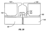
- FIG. 20 depicts a connecting means useful for interconnecting a plurality of modular platform sections.
- FIG. 21 is a top view of a group of modular platform sections that are interconnected using a connecting means according to the invention.
- FIG. 22 is a depiction of an intersection established between four interconnected modular platform sections.
- FIG. 23 is a view of the intersection of four interconnected modular platform sections shown in FIG. 22 , wherein the intersection is substantially sealed by a sealing means.
- FIG. 24 a is a top view of an x-shaped sealing member useful for substantially sealing a gap formed at the intersection of a plurality of interconnected modular platform sections.
- FIG. 24 b is a side view of the x-shaped sealing member shown in FIG. 24 a.
- FIG. 25 is a sectional view of a fluid waste retention member disposed on an outer perimeter portion of a modular platform section.
- FIGS. 26 a and 26 b are plan views of a fence sealing member that has been clipped onto a portion of a fluid retention fence using a clip tab.
- FIGS. 27 a and 27 b are plan views of a retaining fence gap sealing member equipped with a seal extension member.
- FIGS. 28 a and 28 b are plan views of a fence corner seal, in which the corner seal is bridging a gap formed between corner sections of a fluid retention fence.
- FIG. 29 is a top view of a group of assembled modular deck sections following installation atop a plurality of associated platform sections.
- FIG. 30 is a cross-sectional view of the platform shown in FIG. 29 .
- FIG. 31 is a cross-sectional view of the platform shown in FIG. 29 .
- FIG. 32 is a cross-sectional view of a support post disposed in a post hole.
- FIG. 33 is a cross-sectional view of an upper end of the support post shown in FIG. 32 .
- FIG. 34 is a detailed view of a lower end of the support post shown in FIG. 32 .
- FIG. 35 is a platform and deck assembly supported by a support leg, wherein a jacking assembly is disposed above a lift socket located on a topmost portion of the support leg.
- FIG. 36 is the platform and deck assembly shown in FIG. 35 , wherein a hydraulic cylinder is extended down from the jacking assembly until contact with the support post is established.
- FIG. 37 is the platform and deck assembly shown in FIG. 35 , wherein a jacking assembly has lifted the platform and deck assembly off an adjustable nut disposed on the support post.
- FIG. 38 is the platform and deck assembly of FIG. 35 , wherein the adjustable nut has been raised to again support the weight of the lifted platform and deck assembly.
- FIG. 39 is the platform and deck assembly of FIG. 35 , shown after the jacking assembly has been removed and adjustment of the platform height has been completed.
- FIG. 40 is a jacking assembly installed beneath a platform and deck assembly so that the platform can be lifted from the bottom.
- FIG. 41 is a cross-sectional view of a support post, wherein a wedge section is disposed on a tapered shoulder portion of an adjustable nut.
- FIG. 42 is a top view of the support post head shown in FIG. 41 .
- FIG. 43 is a partial rotational view of the support post head shown in FIG. 41 .
- FIG. 44 is a platform floor plan according to an example embodiment of the invention.
- FIG. 45 is a platform building isolated from the example floor plan of FIG. 44 .
- FIG. 46 is a platform section having a bladder tank disposed within.
- FIG. 47 is a cross-sectional view of the platform section and bladder tank assembly shown in FIG. 46 .
- FIG. 48 is a wellhead cellar suitable for use in an arctic platform system.
- FIG. 49 is an alternative wellhead cellar suitable for use in an arctic platform system.
- FIG. 50 is a cross-sectional view of the seals used to secure an inner and an outer skin of a wellhead cellar.
- FIG. 51 is a post hole in which a platform support post is disposed.
- FIG. 52 is an adaptor useful for adding an extension onto the bottom of a support post.
- FIG. 53 is the adaptor of FIG. 52 , with an additional pipe section welded thereon.
- FIG. 54 is a partial section of a bottom portion of the support post shown in FIG. 51 .
- FIG. 55 is a partial section of a support post on which an extension has been added.
- FIG. 56 is a post hole in which a platform support post is disposed.
- FIG. 57 is the post hole of FIG. 56 after the support post has been removed.
- a tundra region 1 is shown in which a number of support posts 2 are disposed in a number of post holes drilled into the tundra.
- the support posts 2 support a substantially level drilling or production platform 4 comprised of numerous interconnected modular platform sections.
- a cylindrical (or other shape) winterizer 6 encloses and winterizes a drilling rig (not shown), and a number of easily transportable modular platform sections 8 are installed around the drilling rig.
- the rig area is heated during drilling operations.
- the rig area is only heated to an intermediate temperature of about +10 degrees F., so that recovered hydrates will not thaw and can be preserved for analysis. In other embodiments, however, the rig area is cooled to permit more comfortable drilling conditions during warmer summer seasons.
- a crane 10 is positioned on a deck portion of platform 4 , and is sufficiently mobile to move around on the deck area so that the crane can be used to carry out a number of different lifting and support functions.
- crane 10 is used to assist in the initial outfitting of the platform, and thereafter to move spools of drilling string and other drilling supplies around the platform during drilling and production operations.
- One or more cranes can also be fixed mounted at key points.
- a group of interconnected housing modules are assembled to provide living quarters for personnel working on the rig.
- the housing platform employs a support post and platform module construction method similar to the platform described above, except that housing modules are disposed on the top of the platform deck instead of drilling modules.
- an arctic platform wherein a plurality of support posts 2 are inserted into a plurality of corresponding post holes 20 that have been drilled into the tundra.
- support posts 2 are fixed in the post holes 20 by a process known as ad freeze, which comprises pouring a fluid slurry (for example, a slurry of water, sand and gravel) into the post holes 20 in order to fix the support posts 2 in place after the slurry freezes and hardens.
- a fluid slurry for example, a slurry of water, sand and gravel
- the support posts are drilled or hammered directly into the ground surface.
- a plurality of modular, interconnectible platform sections 4 are installed atop and supported by the support posts 2 after the support posts have been frozen in place; in still further embodiments, a plurality of drilling container sections 8 are then stacked on top of the platform sections 4 to permit convenient local storage of drilling bits and other equipment related to the drilling operation.
- the well being drilled 22 is disposed beneath a wellhead cellar 24 that supports a wellhead 26 and blowout prevention stack 28 .
- a substructure housing member 30 is disposed above the blowout prevention stack 28 during drilling operations so that the wellhead and blowout stack are safely housed beneath the housing structure 30 .
- drilling rig 32 is disposed above the substructure housing 30 so that drilling rig 32 is instead contained within a winterizer 6 .
- drilling platform 4 is comprised of a plurality of interconnectible, modular platform sections 34 and associated deck sections 36 .
- drilling or production platform 4 comprises 8 platform sections in width, and is supported by 9 rows of evenly spaced support posts 2 frozen into corresponding post holes 20 drilled in the tundra.
- drilling platform 4 is shown in cross section through a centerline of the well bore, drawn along a length of drilling rig 32 .
- wellhead cellar 24 is disposed in operative communication with a pair of long wellhead platform sections 40 and 42 .
- drilling platform 4 further comprises three rows of support posts 2 .
- arctic drilling platform 4 further comprises about sixteen individual, interconnected platform modules, each of which are about 12.5 feet wide and about 50 feet long; the resulting drilling platform 4 is therefore substantially square, and measures about a 100 feet on each side.
- there are about twenty-seven support posts 2 each of which supports the weight and alignment of various platform sections.
- one or more additional support posts 2 are strategically installed to lend additional stability and load capacity to the system.
- additional wells 44 are drilled to serve as backup wellbores in the event the primary wellbore encounters technical problems such as a broken drill bit or a jammed drilling string.
- additional wells 44 are used to drill an underground pipeline routed to a remote location so that production removed from the primary well can be pipelined to a remote location in coordination with the ongoing drilling operation.
- the ability to drill an underground pipeline is particularly useful in environmentally sensitive sites in that removal and transportation of oil, gas and/or hydrates reserves can all be carried out deep beneath the ground surface, thereby reducing disturbance of the surrounding tundra region.
- the additional wells 44 can also be used to establish a field size.
- a plurality of holes 50 are first drilled into a ground surface or frozen tundra region 1 .
- post holes 50 are evenly spaced apart; however, in other embodiments, additional support posts are strategically installed to lend greater stability and structural rigidity to the platform system.
- only a few post holes (or even a single hole) are drilled to receive the support posts of a smaller, stand-alone work module, for example, a nearby secondary well drilled to relieve or apply fluid pressure to the drilling operation.
- a plurality of support posts 2 are then inserted into each of the post holes 50 , with lower portions of the posts being supported by a plurality of post hole ground surfaces 60 , and intermediate portions of the posts being supported by one or more support brackets 64 and 66 attached to provide a temporary surface fitting at the surface level 62 of tundra region 1 while the support posts are being frozen in place within the post holes.
- a slurry comprised of water, sand and gravel mixture is poured into the hole and allowed to freeze.
- adjustable support brackets 64 and 66 are inserted near the top of the hole during the slurry freezing process, so that the tops of the support posts 2 stay accurately aligned during the slurry freezing process.
- a plurality of adjustable shoulder nuts 70 , 72 and 74 are disposed near the tops of each of the support posts 2 ; in the depicted embodiment, the adjustable nuts are disposed at different elevations (as indicated by lines 76 , 78 and 80 ) due to localized inaccuracies in the depths of the post holes.
- adjustable shoulder nut 72 is then raised (for example, by threading the nut up the shaft of a complementary threading formed on a portion of the support post) up to the same elevation level as the other adjustable nuts 70 and 74 (as indicated by lines 80 , 82 and 84 ).
- a level plane is formed to support the later installation of a drilling platform, although in other embodiments, portions of the drilling platform are assembled prior to the drilling of the post holes, and whole sections of previously assembled platform modules are installed on the legs, and then leveled using the adjustable nuts.
- FIG. 7 shows the cross-sectional platform view of FIG. 6 , further comprising a pair of interconnected modular platform sections 92 and 94 installed over a plurality of adjustable shoulder nuts.
- four interconnected modular platform sections are installed over the shoulder nuts of four support posts, for example, the two platform sections 92 and 94 depicted herein and two additional modular sections (not shown) disposed directly behind sections 92 and 94 .
- workers are provided with a level and secure platform surface from which to drill, and effluent and metal cuttings can be contained in the box-like lower body portions of the deck sections.
- a canvas tarp or the like is disposed beneath and around an outer perimeter of the deck sections, and serves as a skirt or trap to ensure that as much waste as possible is captured and recovered from the drilling site.
- a full level of interconnected modular platform sections 100 - 105 is then installed over each of the adjustable shoulder nuts.
- minor adjustments to the heights of the shoulder nuts are then effected in order to correct the level of the platform on an as-needed basis.
- the leveling corrections can be effected when the individual deck sections are being installed, or after all or some of the sections have already been assembled and interlocked.
- a plurality of modular storage sections 106 - 109 is then installed above at least a portion of the platform deck.
- the various storage sections 106 - 109 are strategically arranged so as to conveniently contain the equipment and supplies required to drill and maintain a well, for example, drill string and associated casings, lubricants, power generators, etc.
- the upper portion 120 of a support post 2 further comprises an adjustable shoulder nut 124 disposed at the bottom of the adjustment stroke.
- upper post portion 120 has a reduced cross section 122 , and an adjustable shoulder nut 124 .
- adjustable shoulder nut 124 further comprises an internal threaded region 126 , and a tapered, upwardly facing shoulder member 128 .
- support posts 2 are installed with each of the adjustable shoulder nuts 124 set at the bottom of the adjustment stroke; in other embodiments, however, the adjustable shoulder nuts 124 are set at predetermined positions other than at the bottom of the stroke, or even in random positions, depending upon the particular operational requirements of the drilling environment.
- a tapered section 134 is provided at the top of adjustable nut 124 to allow wedges or shims to be dropped inside a space formed when a module is placed onto a post, thereby lending lateral support to the post as well as vertical support.
- one or more fluid receiving fittings 130 are provided at the top of the support post for receiving and circulating a heating or cooling fluid within a body portion of the post, and a threaded receiving member 132 is provided for attachment of a lifting means.
- receiving member 132 is not threaded, and instead comprises a slip-toothed fastening assembly; in still further embodiments, receiving member 132 comprises an inverted nut and bolt receiving assembly for receiving a lifting means that has been lowered from the deck surface disposed above.
- FIG. 11 shows an adjustable nut that was initially set at a position higher than the bottom of the adjustment stroke, for example, near the middle of the adjustment stroke in order to build up a platform section disposed on a downward slope.
- adjustable shoulder nut 124 has been threaded up the support post to a higher position as a method of setting an upper shoulder 126 of the adjustable nut at the same elevation as the shoulders on neighboring posts.
- a plurality of interconnected modular platform sections 50 is provided, each of which is installed atop a plurality of support posts.
- the lengths of the platform sections are elongated relative to their widths; in a presently preferred embodiment, the lengths of the platform modules are elongated relative to their widths by a ratio of about 4:1.
- each platform section is about 12.5 feet wide and about 50 feet long.
- sixteen such platform sections are combined to provide a substantially square deck surface that is about 100 feet in both length and width.
- platform 52 is supported by twenty seven different support posts 54 , each of which engage various platform sections from beneath the platform.
- a beam member 62 which provides bridging support between support posts 64 and 66 .
- another beam member 70 which provides bridging support between support posts 72 and 74 .
- the underside of platform section 80 is a flat plate and includes a plurality of stiffening members 82 ; in some embodiments, stiffening members 82 are not intended to be structural or load bearing members, and are instead designed to support an accumulation of liquids and effluent that usually develops on a drilling platform.
- an interlocking method of securing the platform modules to one another permits disposition of but a single support post at each platform intersection, and adjacent platform modules are all supported by that single post.
- the support post is not necessarily attached to each of the surrounding platform sections.
- platform sections are attached to the support posts in such a fashion as to provide greater support in the direction of a line between support post 64 and support post 66 ; in this embodiment, greater support would also be provided between support post 72 and support post 74 .
- a load placed anywhere on the individual deck sections will be supported initially by the deck surface 120 , which in turn transfers the weight load in the direction indicated by arrow 130 (see FIG. 12 ) toward beam sections 82 and 96 disposed beneath the deck.
- the weight of the load is then transmitted down the side beams in the direction of arrow 132 (see FIG. 12 ) toward the support posts, which in turn directs the weight into the surface of the tundra.
- rectangular beam 82 is established by assembly of a plurality of interlocked platform modules disposed on a side 94 portion of platform section 80 ; likewise, opposed rectangular beam 96 is established by assembly of a plurality of interlocked platform modules disposed on another side 104 of platform section 80 .
- a deck section 120 is installed and then locked into place.
- deck section 120 provides direct support for the various equipment and supply packages loaded on top of the deck.
- beam sections 82 and 96 provide support in the direction of the support posts 64 and 72 shown in FIG. 12 .
- deck section 120 comprises a composite structure having a top plate 122 and a bottom plate 124 , separated by a foam mixture 126 disposed in an interior region established within the platform modules.
- foam mixture 126 is a polyurethane foam mixture that not only stabilizes and supports the structural integrity of the top and bottom plates, but also provides a compressive strength sufficient to support heavy equipment loads placed on top of the deck surface 120 .
- the polyurethane foam mixture 126 also dampens the loud noises and structural vibrations typically created during drilling operations.
- FIGS. 14 and 15 show a plurality of assembled modular platform sections similar to the embodiments described in FIGS. 12 and 13 .
- the platform is supported by twenty-seven support posts 54 , which engage the various platform sections from underneath.
- a beam member 62 that provides bridging support between support posts 64 and 66 .
- another beam member 70 which provides bridging support between support posts 72 and 74 .
- the bottom of platform section 80 is a flat plate and includes a plurality of stiffening members 82 , which are not intended to be structural or load bearing in nature other than having sufficient capacity to support an accumulation of fluids that build up during drilling operations.
- a single support post is disposed at each platform intersection, and the adjacent platform modules are all supported by that single post. While each platform section corner is near to and supported by a support post, the support post is not necessarily disposed in that platform section; the corners of some of the platform sections are supported by only the interlocking connection members disposed therebetween.
- a first platform section 60 is disposed adjacent to a second platform section 140 ; a first deck section 142 is installed over platform section 60 , and a second deck section 144 is installed over platform section 140 .
- a fence member 152 projects upwardly from an upper surface 150 of platform section 60 .
- upper surface 160 of platform section 140 has a hook 162 disposed over the fence member 152 .
- hook 162 is formed structurally integral with platform section 160 , and provides support for the side of platform section 160 ; in other embodiments, however, hook 162 is not formed structurally integral with platform section 160 , and is instead mechanically affixed to the system to provide support for the side of platform section 160 .
- a first platform section 60 is logically supported by at least four different support posts 64 , 66 , 72 and 74 .
- a second platform section 160 is supported by only two additional support posts 162 and 164 , while support on the opposite side is achieved by means of a hooking member 163 engaged over a portion of fence member 152 shown in FIG. 16 .
- platform section 170 is supported by only two additional support posts 172 and 174 , though platform section 170 also gains support from support posts 162 and 164 on the opposite side by means of the mentioned hook and fence member combination.
- additional platform sections 180 , 182 , 184 , 186 and 188 are successively installed, in each instance installation requiring only two additional support posts and an opposed, complementary hook and fence member combination to ensure a secure and reliable connection.
- platform section 190 employs two additional support posts 192 and 194 at the end of the platform section disposed furthest away from platform section 170 .
- platform section 190 gains additional support from attachment to support posts 164 and 174 , and also from a hook and fence member combination disposed at the end most proximate to platform section 170 . Consequently, platform section 200 requires only a single additional support post 202 , provided said support post is employed in combination with a hook and fence member support means at each of intersections 204 and 206 .
- Additional platform sections 210 , 212 , 214 , 216 , 218 and 220 will also require only a single additional support post each, again provided the configuration includes an appropriate hook and fence member combination on two of the sides disposed opposite the support post.
- FIGS. 18-21 again show a drilling platform comprised of a group 52 of platform sections that have been interconnected for support of equipment storage modules that will later be installed on top of various portions of the platform. As shown, the platform sections are supported by twenty-seven support posts 54 , which engage various platform sections from locations disposed beneath the platform.
- support posts 54 engage various platform sections from locations disposed beneath the platform.
- weight loads can be directed and distributed in virtually any direction along the platform, and additional interconnections between platform sections can be established to either support weight loads disposed on deck sections, or to otherwise lend stability and structural rigidity to the resulting platform system.
- a support post 2 is shown disposed near an intersection 230 of four interconnected platform modules 232 , 234 , 236 and 238 .
- a plurality of connecting hooks 240 , 242 , 246 and 248 are disposed over complementary fence members 250 , 252 , 254 and 256 , so that the several associated platform sections are securely interconnected.
- the hook and fence member assemblies also serve to effectively seal the intersection 240 where the platform sections are joined, at least insofar as accumulated water and the like will easily pass from one platform section to another across body portions of the hook and fence locking assemblies.
- Intersection 230 is more problematic. For example, virtually any liquid can pass through the space formed at the center of the four-corner intersection, and then pass between platform sections and down onto the ground surface disposed below. According to one aspect of the invention, therefore, a sealing member is provided to close the space formed at intersection 230 , the seal generally being disposed on the top side portion of the intersection, although installation of the seal from the bottom side of the intersection 230 is also contemplated.
- the sealing member which in this case is referred to as an x-seal because of its shape, extends in each of four directions at least as far as a series of sealing grooves 260 that have been cut into body portions of each of the associated fence members 250 , 252 , 254 and 256 .
- a platform sealing member 270 is dropped over a four-corner intersection where four assembled platform modules have been interconnected.
- the body of the seal is substantially in direct contact with body portions of the fence members 250 , 252 , 254 and 256 (see FIG. 22 ), and therefore also directs water or other accumulated fluids across away from the intersection 230 of the interconnected platform modules.
- a plurality of small grooves disposed in the fence members cut crossways across the fence members so that any fluid that would otherwise tend to run along the bottom of the x-seal will instead be diverted in another direction by means of fluid contact with any one of the series of small cut grooves 260 depicted in FIG. 22 .
- an appropriate x-shaped seal member 270 is shown, which in some embodiments comprises a thin metal plate 274 equipped with a plurality of leg members 272 , which depend from and around various portion of thin plate 274 .
- leg members 272 are formed structurally integral with thin plate 274 , though in other embodiments leg members 272 comprise a plurality of separate pieces (e.g., a number of small metal rectangles) affixed to thin plate 274 using a known connection method, for example, welding the metal rectangles to the thin plate.
- safety fence 280 comprises or retention plate 282 , which is either welded on or mechanically affixed to a body portion 284 of safety fence 280 .
- retention plate 282 includes a portion having a double bend 284 that slips into and engages a top portion of platform section 288 at a predetermined location so as to establish the desired fluid retention fence 280 .
- safety fence 280 causes splashing liquids to be diverted back toward the interior surfaces of the interconnected platform sections, though in one particular embodiment, re-directed fluid flow is allowed to drain into a container portion of a platform section by means of one or more drain holes 290 .
- cable races are attached to the retention plates or, in further embodiments, to the platform perimeter.
- individual fluid waste retention fence members are necessarily going to be fabricated in advance at finite, predetermined lengths.
- the fluid waste retention fence member measures about twelve and one-half feet long.
- fence seal sections 300 are fastened to a waste retention member using known fastening means such as a screw or a nut and bolt assembly.
- the fence seal 300 is clipped onto those portions of the fence disposed nearest the gaps formed between fence sections using one or more clip tabs 302 and 304 .
- fence seal 300 is clipped onto the safety fence by hooking each of clip tabs 302 and 304 over a top lip portion of the kick plate.
- a vertical fence seal portion 300 is fabricated so that it is about the same height as the terminal vertical portion of the kick plate, so that water or other fluids are directed back toward the interconnected platform sections.
- a retaining fence gap sealing member 312 is provided, in which the sealing member further comprises an extension member disposed thereon that is similar in both nature and function to the previously discussed four-way seal, so that excess water that seeps along an interior surface of the fence seal will again be redirected to a region contained within the perimeter of the fence.
- platform sections on which the fence members are affixed have a plurality of cut grooves disposed beneath the sealing member that further prevents seeping fluids from migrating down the sides of the platform sections.
- a fence corner seal 320 is disposed so that the gap that forms between two sections of fence installed at corners of the platform is bridged.
- the corner seal functions similar to the other fence seals discussed above, except that the corner seal also engages multiple sections of the fence.
- each of the fence sections upon which the corner seal is installed is disposed at about a ninety-degree angle relative to the other.
- a number of assembled modular platform sections 50 are depicted following the installation of a plurality of deck sections atop upper portions of the platform sections.
- one or more manholes 54 is disposed at each end of the deck sections, except for platform section 56 , which has a shortened deck (and thus a manhole 54 disposed at only one end) due to the location of the platform's wellhead cellar 61 .
- a utilities communication pipe 60 within a body portion of each of the deck sections is a utilities communication pipe 60 , which, in certain embodiments, is configured to run along an entire length (or width) of the platform section.
- utility pipe 60 has a predetermined number of regularly spaced junctions, permitting convenient access points for installation and maintenance of utilities related equipment (e.g., fiber optics bundles, electrical wiring, etc.).
- utilities communication pipe 60 comprises a plurality of junctions disposed at irregularly spaced locations disposed along a length of the pipe.
- communication pipes 60 (and the various junctions and utility access points disposed thereupon), serves as the framework for distribution of power and other utilities around the surface of the platform during drilling operations.
- each of the deck sections are slightly greater in length than the utilities communication pipes contained within, so that sufficient room remains within the interior of the deck module to install one or more power boxes, water junctions, or utility cross-connections, near the terminal ends of the communication pipes.
- one or more utilities communication pipes 60 are used to accommodate installation of electrical power lines, telephone lines, fiber optic connections, gas hoses, fuel lines, etc.
- deck sections 70 and 72 are disposed atop platform sections 74 and 76 , though those of ordinary skill in the art will appreciate that the deck sections can also be assembled in combination with other types of platform modules.
- deck sections are constructed by stacking one or more layers, wherein each layer further comprises one or more communication pipes.
- pipes 84 and 86 extend into the deck in order to facilitate utilities communication.
- Deck section 70 has an upper plate 88 and a lower plate 90 , each of which are usually formed from a metal or composite material of some type.
- upper plate 88 and/or lower plate 90 are formed from an aluminum plate, though in other embodiments an aluminum alloy or other combination of materials is preferred.
- an insulation material is installed in the space or gap established between the utilities communication pipes.
- polyurethane foam is placed into the space between the communications pipes to lend compressive resistance to the deck plate disposed above the crawl space.
- a utility junction 100 is disposed in proximity to utilities communication pipes 102 and 104 .
- the horizontal utility pipes intersect a vertical junction pipe 106 that has been cut to reflect the actual height of the space established between upper plate 88 and lower plate 90 .
- a drain hole 106 is opened in the lower plate 90 , so that utility lines and the like can be fed into and through the platform sections disposed below.
- a vertical pipe having a threaded engagement means 110 is prepared, so that utility lines can also be drawn out of the engagement means 110 and up into other modules affixed on top of the deck.
- a plug is threaded into the threaded engagement means 110 when the portal is not in use, thereby providing a smooth deck surface that is substantially uninterrupted by open manholes.
- FIG. 32 is a detailed view of a support post 50 according to the invention.
- support post 50 is inserted into a post hole 52 that has been drilled into a ground surface.
- support post 50 has an interior space 54 established for receiving a slurry 56 of water, sand and gravel.
- an external surface of the support post is smooth or flat.
- a lower portion 60 of support post 50 has a spiral support fin 62 , and an upper post end 64 is configured to fit into a receiving socket 66 disposed in the bottom of platform section 68 .
- FIG. 33 is a detailed view of an upper end 64 of the support post 50 shown in FIG. 32 , further comprising a process fitting 70 that allows fluids to be pumped down into a conduit or pipe 80 disposed in a body portion of the support post 50 .
- fluids pumped into pipe 80 travel to the bottom of support post 50 , and a return flow is established by directing accumulated fluid pressure toward a process fitting disposed in flanged member 72 .
- support post 50 further comprises a plurality of threaded ports 74 , so that support post 50 can be installed using an attached padeye or other fitting device (not shown).
- spiral fin 82 is fabricated from two metal plates, viz., a lower, rolling spiral plate 84 that extends substantially perpendicularly from an outer diameter 86 of lower pipe section 88 , and an upper, conical spiral plate 90 that extends downwardly at an angle of about thirty to forty five degrees.
- Rolling spiral plate 84 and conical spiral plate 90 are joined together by, for example, a known welding or sintering process, so as to establish a hollow fluid transport space 92 disposed within spiral fin 82 .
- the exterior surface of the support post is substantially smooth and the fluid transport space is located within an interior region of the support post.
- a fluid solution is pumped downward through pipe 80 and into spiral fin 82 .
- the fluid circulates around the spiral fin 82 down to the bottom of the post 100 , and then vents into an internal bore 106 of support post 50 through transport hole 104 .
- the fluid solution then circulates back up the body of internal bore 106 .
- a liquid or gaseous medium can be pumped down the pipe 80 and around spiral fin 82 , and then back up the internal bore 106 of support post 50 to either cool or heat the ground surface area surrounding support post 50 .
- a very cold fluid or gas is pumped through pipe 80 into the body of the post, so as to ensure that the surrounding ground surface will remain firmly frozen.
- a warm fluid or gas is instead pumped through pipe 80 in order to melt the ground surface around the support post, so that the support post can then be removed from its moorings and more easily retrieved when drilling operations are complete.
- the fluid transportation means is vented to a surrounding ground surface using jetting ports or the like in order to make removal of the support posts easier.
- a fluid such as a food-grade glycol, which has a freezing temperature well below the lowest anticipated temperature of the surrounding tundra, is employed to facilitate the aforementioned freezing steps.
- food-grade glycol is also biodegradable, and thus will have only a limited impact on the surrounding ground surface.
- fluid solutions for example, chilled air, heated air or hot steam, can be pumped through the support post 50 in order to carry out the aforementioned freezing and heating.
- a platform and deck assembly 350 is supported by a support post 360 , wherein a jacking assembly 370 is disposed above a lift socket 365 located on a topmost portion of the support post 360 .
- a hydraulic cylinder 375 is then extended down from the jacking assembly 370 until contact with the support post lifting socket 365 is established.
- the engagement means provided to ensure a reliable mechanical interface between cylinder head portion 380 and lifting socket 365 is a slip-toothed sprocket assembly.
- the engagement means comprises a known fastener assembly, for example, a nut and bolt assembly.
- hydraulic cylinder 375 is shaped like a piston, and exerts a downward force against the head of the support post so as to engage the two members via the fastening means.
- the hydraulic cylinder member 375 is a telescoping cylinder, so that successive, concentric portions of the cylinder are revealed as the cylinder is extended to engage with the support post lifting socket 365 , and the platform and deck assembly 350 are then lifted.
- adjustable nut 368 is relieved of its weight load and can then be height-adjusted without further disturbing the level or stability of the surrounding platform.
- FIG. 38 after adjustable nut is 368 has been re-adjusted to a desired setting, platform and deck assembly 350 is set back down onto a flanged receiving portion 369 of adjustable nut 368 by means of hydraulic cylinder 375 , and cylinder head 380 is unfastened or otherwise withdrawn from support post lifting socket 365 .
- jacking assembly 370 can then be removed from the vicinity of support post 360 and used elsewhere on the platform if desired.
- platform and deck assembly 350 need not necessarily be lifted from above in order to relieve the weight load disposed on the support post 360 .
- jacking assembly 390 can also be installed underneath the platform and deck assembly 350 , and then used to lift the platform off of the support post 360 by pushing a top surface of the cylinder against a bottom surface of the platform and deck assembly 350 and then driving the cylinder upward using the cylinder's hydraulic system.
- one or more cylinder retaining pins can also be disposed in-between the jacking assembly's telescopic cylinder members in order to provide a standardized range of support post height adjustments.
- a plurality of retaining pins is inserted through regularly spaced receiving holes formed in body portions of the inner, middle and outer telescopic cylinder members. As the cylinder progresses through a stroke cycle and retaining pins are inserted into the receiving holes, a basic height for the jack assembly is established at one of several predetermined elevations.
- a bottom jack assembly is positioned adjacent to a side portion of a platform in such a fashion that the jack's hydraulic cylinder traverses a first portion of its stroke distance.
- a chain or other lifting means is then wrapped around the raised cylinder head, and the pins are removed from the cylinder's telescopic body sections.
- the telescopic sections are pulled back in and the pins are reinserted.
- the cylinder is again extended, and slack in the restraining chain is withdrawn, so that the height of the cylinder head is raised; at that point, the cylinder head is held in place by only the shortened restraining chain.
- the pins are then pulled out of the receiving holes again, and the cylinder is retracted.
- the telescopic cylinder members are raised to a higher position and then re-pinned, this process being repeated until the cylinder head has been raised to its desired height using only the hydraulic lift strength of the jack assembly.
- the jack assembly is slid into place under a desired portion of the platform, and the cylinder head is again extended to permit final adjustment of the height of the support posts.
- an installed support post 54 comprises a tube-like member 50 disposed through a body portion of a platform section 52 , wherein the support post 54 is inserted from below into a cylindrical interior space formed in post tube 50 .
- An adjustable nut 56 is disposed on a body portion of support post 54 so as to engage a bottom surface 58 of platform section 52 .
- engagement between adjustable nut 56 and platform bottom surface 58 further comprises an insulating member 60 .
- the insulating member 60 is formed from a poorly conductive material such as, for example, Delrin or UHMW polyethelene, the insulating member serves to establish an electrical ground between the steel adjusting nut 56 and the aluminum platform section 52 .
- a tapered receiving member 62 disposed on an upper portion of adjustable nut 56 resides within tube member 50 after the support post is installed.
- a first chocking assembly 70 is then lowered down into the space formed between the tube member 50 and support post 54 so as to engage both the tapered receiving member 62 and an inner wall surface 78 of tube member 50 .
- a lower wedge member 72 is disposed to engage the adjustable nut 56 at a lower location, and to support an additional tapered receiving section 74 disposed on a topmost portion of chocking assembly 70 .
- an upper wedge 76 is disposed to engage the topmost portion of tapered receiving section 74 and inner wall surface 78 of tube member 50 .
- FIG. 42 is a top view of the support post head shown in FIG. 41 .
- several chocking assemblies 70 are disposed around a perimeter region of support post head 80 in order to hold the support post 54 securely in place and lend additional stability and structural rigidity to the system after installation is complete.
- FIG. 43 is a perspective view of the support post head shown in FIG. 41 , wherein several of the design features described above with respect to FIG. 42 are emphasized.
- FIG. 44 is a proposed platform floor plan in which the general arrangements of storage buildings and other necessary structures are depicted. Care must be given to the layout and grouping of platform structures so that related equipment is strategically stored, safe and comfortable housing is available for platform personnel, and to ensure that the rig is in compliance with strict fire and safety codes.
- a five-foot radius around the bell of any drilling rig is considered a Division One explosion environment, and all electrical equipment used in the area must be configured to accommodate the requirements associated with a Class One Division One area.
- Most enclosed structures that have a door opening out to a Division One environment are considered Class One Division Two explosive environments, environments that, under the API regulations, are regulated nearly as restrictively as Class One Division One areas.
- virtually all electrical equipment used on the rig, including computers and telephones, must be reviewed for electrical explosion potential in order to comply with the mentioned industry regulations.
- a driller's doghouse 50 is disposed on one side of the drilling rig 52
- a company man house 54 is disposed on an opposite side of the rig 52 .
- Both the driller's doghouse and the company man house have a picture window 56 and 58 , so that personnel can look onto the drilling floor 60 .
- both the driller's doghouse and the company man house would also be desirable for both the driller's doghouse and the company man house to have a doorway that permits personnel stationed in these offices to walk out onto the rig floor to perform work or conduct discussions regarding rig activities; however, the presence of a doorway between the rig floor and either the driller's doghouse or the company man house would cause these areas to be classified as Division Two areas, and since both the drillers and the company men often have need for telephones and portable computers and the like, most of which are not explosion-proofed, it has in the past been the case that convenient doors between the rig floor and the personnel stations are not present.
- rig floor access difficulties are overcome by constructing a company man house 54 that is actually a combination of a company man room 70 and a computer and communications room 72 .
- a door 80 opens into a small hallway 82 , rather than directly into the company man room 70 .
- the small hallway 82 passes straight through the company man house 54 and is fully opened to the environment on a side 84 opposite the door 80 . Since door 80 opens into a hallway 82 that is open to the environment, hallway 82 becomes a non-classified area, and company men can use the telephones and computers provided in computer room 72 without conflicting with the industry regulations.
- FIGS. 46 and 47 an embodiment of the invention depicted in FIGS. 46 and 47 comprises a platform section 50 that has a deck section 52 installed on top of the platform.
- support foam 54 disposed within deck section 52 provides a layer of insulation at the top of the deck portion; in a presently preferred embodiment, the layer of insulation is about six inches thick.
- a plurality of six-inch insulation members 56 have also been added to the ends, bottom, and both sides of the platform and deck sections, effectively making the storage module a large thermal container.
- the floor of thermal container 52 further comprises an electric heating element 60 ; lying on top of the heating element is a balloon type tank or collapsible pillow tank 62 .
- the balloon tank stores fresh water that can later be processed into either potable water or water suitable for use in showers and sinks.
- balloon tank 62 is used to store other liquids, for example, diesel fuel or well operation fluids.
- a pump 70 is used to draw fluid out of the bladder tank prior to transfer of the fluid into other parts of the platform structure.
- pump 70 is used to draw liquids from other platform sections, and to pump the drawn fluids into the bladder tank through appropriate process connections 72 , for example, a metal pipe or durable plastic conduit connection.
- FIG. 48 is a cross-sectional view of a wellhead cellar according to one aspect of the invention, in which an outer portion of the wellhead cellar is comprised of multiple layers, for example, an inner skin and an outer skin, with two-part polyurethane foam insulation disposed between the inner and outer skins.
- an outer portion of the wellhead cellar is comprised of multiple layers, for example, an inner skin and an outer skin, with two-part polyurethane foam insulation disposed between the inner and outer skins.
- there are at least two levels of seals provided to ensure the unit is as environmentally secure as possible and that the ground surface is protected from inadvertent spills.
- the disclosed wellhead cellar also permits the entire drilling operation to be carried out without disturbing any of the ground surface except for the production hole.
- the wellhead center cellar further comprises additional sets of casing and the like suitable for use in additional wellbores.
- the backup casings are also sealed within the wellhead cellar to prevent leakage, and to maintain the environmental integrity of the drilling operation.
- a ladder or stairs provide access to personnel required to move into and out of the wellhead cellar.
- a wellhead cellar sealing assembly engages an outermost stream of production casing.
- the seals comprise an inner and outer skin, with polyurethane foam disposed in-between.
- each of the seals are energized using bolts attached by known fasteners in order to provide a secure and reliable sealing assembly for the protection of wellhead.
- Other means for energizing the seals include introduction of low pressure air feeds, for example, an air feed having about 2 PSI, so that the seals are held fast after attachment by means of compressive pressure or the use of a sealant such as foam.
- FIG. 51 is a post hole in which a platform support post 50 is disposed according to further aspects of the invention.
- the support post 50 has an adjustable nut 56 for making fine adjustments to the level of the platform 52 disposed thereon, and a fluid transfer means 58 that permits fluid to be pumped from the platform down inside the body of the support post 52 for heating or cooling operations.
- a lower end 60 of support post 50 is contoured to permit pumped fluids to flow toward the bottom of the support post for full, uniform heating of the support post.
- a smaller diameter section 62 is for engagement with an extension member.
- an adaptor 70 useful for adding an extension onto the bottom of a support post is provided.
- adaptor 70 has an internal bore 72 sized to engage a smaller diameter section 62 of the bottom of support post 50 .
- one or more fastening bolts 74 are also provided; in a particular example embodiment, the fastening bolts 74 are disposed at 90 degree intervals around the circumference of the device, and engage and lock onto the bottom of the support post 50 .
- Disposed on a bottom portion of the adapter 70 is an extension receiving member 76 , sized to engage a piece of extension pipe that is added to the bottom of the adapter 70 .
- FIG. 53 shows the adaptor 70 of FIG.
- the extension member 80 is welded onto a bottom portion of the extension receiving member 76 , though in other embodiments any known fastening means will suffice so long as the connection between the extension member 80 and the extension receiving member 76 is secure and dependable.
- any known fastening means will suffice so long as the connection between the extension member 80 and the extension receiving member 76 is secure and dependable.
- certain embodiments use shear pins or the like to secure the extension member and the extension receiving member so that the connection will break apart when a predefined amount of force is applied.
- a bottom portion of support post 50 has a lower end 60 sized so as to engage within an interior surface of extension receiving member 72 (see FIG. 52 ).
- the support post has an extension member added, with the outer surface of lower end 60 being attached to the extension receiving member 72 using a plurality of fastening bolts 74 .
- a post hole 100 is depicted in which a platform support post is disposed.
- Extension member 84 has already been friction-locked to a bottom end of the support post.
- a slurry of water, sand and gravel is added to freeze the support post in place. At this point, the support post is ready for supporting the raised load for which it was designed.
- the post hole shown in FIG. 56 is depicted after removal of the support post from the post hole.
- the support post is heated using circulated warm fluid so as to unfreeze the post from the surrounding ground formation.
- the plurality of bolts used to fasten the extension member to the extension receiving member are then removed or sheared, so that the support post can in turn be removed from the adapter and extension member.
- the adapter and extension member remain in the ground afterward, buried well beneath the surface of the surrounding ground formation.
- the adapter and extension member are left in the ground about fifteen to twenty feet beneath the ground surface.
- the adapter and extension are forever abandoned, and the post hole is filled in or covered over so that only minimal signs of the drilling operation are imprinted on the surrounding ground surface.
- the adapter and extension member assembly are re-used whenever production from the site is again desired, and thus the post hole is not filled in or covered over.
- the adapter and extension member assembly are abandoned, and the upper portion of the post hole is refilled with a slurry of sand and ice.
- the post hole is re-filled with a mixture of tundra and ice, and thus the former drilling site cannot easily be discerned from the surrounding tundra after operations have been completed and the platform has been removed.
Landscapes
- Engineering & Computer Science (AREA)
- Life Sciences & Earth Sciences (AREA)
- Structural Engineering (AREA)
- Paleontology (AREA)
- General Engineering & Computer Science (AREA)
- Civil Engineering (AREA)
- General Life Sciences & Earth Sciences (AREA)
- Mining & Mineral Resources (AREA)
- Soil Sciences (AREA)
- Environmental & Geological Engineering (AREA)
- Agronomy & Crop Science (AREA)
- Earth Drilling (AREA)
- Legs For Furniture In General (AREA)
- Conveying And Assembling Of Building Elements In Situ (AREA)
- Special Wing (AREA)
- Road Repair (AREA)
- Road Paving Structures (AREA)
Priority Applications (11)
| Application Number | Priority Date | Filing Date | Title |
|---|---|---|---|
| US11/704,614 US7410327B2 (en) | 2003-04-08 | 2007-02-09 | Arctic platform |
| US12/221,231 US20080292411A1 (en) | 2003-04-08 | 2008-07-31 | Arctic platform |
| US12/221,173 US20080286053A1 (en) | 2003-04-08 | 2008-07-31 | Arctic platform |
| US12/221,230 US20080292412A1 (en) | 2003-04-08 | 2008-07-31 | Arctic platform |
| US12/555,303 US20100003084A1 (en) | 2003-04-08 | 2009-09-08 | Arctic Platform |
| US12/561,915 US7988384B2 (en) | 2003-04-08 | 2009-09-17 | Arctic platform |
| US12/561,906 US20100003086A1 (en) | 2003-04-08 | 2009-09-17 | Arctic Platform |
| US12/874,662 US20100329795A1 (en) | 2003-04-08 | 2010-09-02 | Arctic platform |
| US13/086,771 US20110188944A1 (en) | 2003-04-08 | 2011-04-14 | Arctic Platform |
| US13/208,025 US8226326B2 (en) | 2003-04-08 | 2011-08-11 | Arctic platform |
| US13/342,489 US20120124934A1 (en) | 2003-04-08 | 2012-01-03 | Arctic Platform |
Applications Claiming Priority (3)
| Application Number | Priority Date | Filing Date | Title |
|---|---|---|---|
| US46160203P | 2003-04-08 | 2003-04-08 | |
| US82059704A | 2004-04-08 | 2004-04-08 | |
| US11/704,614 US7410327B2 (en) | 2003-04-08 | 2007-02-09 | Arctic platform |
Related Parent Applications (1)
| Application Number | Title | Priority Date | Filing Date |
|---|---|---|---|
| US82059704A Continuation | 2003-04-08 | 2004-04-08 |
Related Child Applications (3)
| Application Number | Title | Priority Date | Filing Date |
|---|---|---|---|
| US12/221,231 Division US20080292411A1 (en) | 2003-04-08 | 2008-07-31 | Arctic platform |
| US12/221,173 Division US20080286053A1 (en) | 2003-04-08 | 2008-07-31 | Arctic platform |
| US12/221,230 Division US20080292412A1 (en) | 2003-04-08 | 2008-07-31 | Arctic platform |
Publications (2)
| Publication Number | Publication Date |
|---|---|
| US20070163186A1 US20070163186A1 (en) | 2007-07-19 |
| US7410327B2 true US7410327B2 (en) | 2008-08-12 |
Family
ID=33299839
Family Applications (11)
| Application Number | Title | Priority Date | Filing Date |
|---|---|---|---|
| US11/704,614 Expired - Lifetime US7410327B2 (en) | 2003-04-08 | 2007-02-09 | Arctic platform |
| US12/221,173 Abandoned US20080286053A1 (en) | 2003-04-08 | 2008-07-31 | Arctic platform |
| US12/221,231 Abandoned US20080292411A1 (en) | 2003-04-08 | 2008-07-31 | Arctic platform |
| US12/221,230 Abandoned US20080292412A1 (en) | 2003-04-08 | 2008-07-31 | Arctic platform |
| US12/555,303 Abandoned US20100003084A1 (en) | 2003-04-08 | 2009-09-08 | Arctic Platform |
| US12/561,906 Abandoned US20100003086A1 (en) | 2003-04-08 | 2009-09-17 | Arctic Platform |
| US12/561,915 Expired - Lifetime US7988384B2 (en) | 2003-04-08 | 2009-09-17 | Arctic platform |
| US12/874,662 Abandoned US20100329795A1 (en) | 2003-04-08 | 2010-09-02 | Arctic platform |
| US13/086,771 Abandoned US20110188944A1 (en) | 2003-04-08 | 2011-04-14 | Arctic Platform |
| US13/208,025 Expired - Lifetime US8226326B2 (en) | 2003-04-08 | 2011-08-11 | Arctic platform |
| US13/342,489 Abandoned US20120124934A1 (en) | 2003-04-08 | 2012-01-03 | Arctic Platform |
Family Applications After (10)
| Application Number | Title | Priority Date | Filing Date |
|---|---|---|---|
| US12/221,173 Abandoned US20080286053A1 (en) | 2003-04-08 | 2008-07-31 | Arctic platform |
| US12/221,231 Abandoned US20080292411A1 (en) | 2003-04-08 | 2008-07-31 | Arctic platform |
| US12/221,230 Abandoned US20080292412A1 (en) | 2003-04-08 | 2008-07-31 | Arctic platform |
| US12/555,303 Abandoned US20100003084A1 (en) | 2003-04-08 | 2009-09-08 | Arctic Platform |
| US12/561,906 Abandoned US20100003086A1 (en) | 2003-04-08 | 2009-09-17 | Arctic Platform |
| US12/561,915 Expired - Lifetime US7988384B2 (en) | 2003-04-08 | 2009-09-17 | Arctic platform |
| US12/874,662 Abandoned US20100329795A1 (en) | 2003-04-08 | 2010-09-02 | Arctic platform |
| US13/086,771 Abandoned US20110188944A1 (en) | 2003-04-08 | 2011-04-14 | Arctic Platform |
| US13/208,025 Expired - Lifetime US8226326B2 (en) | 2003-04-08 | 2011-08-11 | Arctic platform |
| US13/342,489 Abandoned US20120124934A1 (en) | 2003-04-08 | 2012-01-03 | Arctic Platform |
Country Status (8)
| Country | Link |
|---|---|
| US (11) | US7410327B2 (es) |
| EP (2) | EP1620628A4 (es) |
| CA (4) | CA2509408C (es) |
| DK (1) | DK2362022T3 (es) |
| EA (1) | EA008873B1 (es) |
| ES (1) | ES2664602T3 (es) |
| PT (1) | PT2362022T (es) |
| WO (1) | WO2004092529A2 (es) |
Cited By (6)
| Publication number | Priority date | Publication date | Assignee | Title |
|---|---|---|---|---|
| US20080286053A1 (en) * | 2003-04-08 | 2008-11-20 | Baugh Benton F | Arctic platform |
| US8393116B2 (en) | 2010-09-30 | 2013-03-12 | Composite Advantage, Llc | Elevated platform systems including fiber reinforced composite panels |
| US8672043B2 (en) | 2010-11-03 | 2014-03-18 | Nabors Alaska Drilling, Inc. | Enclosed coiled tubing boat and methods |
| US20190178046A1 (en) * | 2017-12-13 | 2019-06-13 | China University Of Petroleum (East China) | Anti-settling Apparatus and Method and Apparatus for Checking the Same, and Apparatus for Preventing Settlement of Well |
| US10435861B2 (en) * | 2017-06-30 | 2019-10-08 | TorcSill Foundations, LLC | Pad site construction and method |
| US20200095744A1 (en) * | 2018-09-20 | 2020-03-26 | Admares Group Oy | Method for constructing building on water-body |
Families Citing this family (23)
| Publication number | Priority date | Publication date | Assignee | Title |
|---|---|---|---|---|
| US6715964B2 (en) | 2000-07-28 | 2004-04-06 | Peratrovich, Nottingham & Drage, Inc. | Earth retaining system such as a sheet pile wall with integral soil anchors |
| EP2235290A4 (en) * | 2007-12-18 | 2014-05-21 | Uttamrao Hanumantrao Jadhav | ARCHITECTURAL STRUCTURE AND METHOD THEREOF |
| WO2009134125A1 (en) * | 2008-04-29 | 2009-11-05 | Itrec B.V. | Floating offshore structure for hydrocarbon production |
| US20120043136A1 (en) * | 2008-08-15 | 2012-02-23 | Dirk Alfermann | Drilling rig for deep well drilling |
| US8444348B2 (en) * | 2009-06-30 | 2013-05-21 | Pnd Engineers, Inc. | Modular offshore platforms and associated methods of use and manufacture |
| US10024017B2 (en) | 2009-09-11 | 2018-07-17 | Pnd Engineers, Inc. | Cellular sheet pile retaining systems with unconnected tail walls, and associated methods of use |
| US9010462B2 (en) * | 2011-02-17 | 2015-04-21 | Fenix Energy Solutions Ltd. | Low headroom confined space geoexchange drilling system and method |
| US8950980B2 (en) | 2012-05-15 | 2015-02-10 | Robert L. Jones | Support platform for an oil field pumping unit using helical piles |
| CN102704872B (zh) * | 2012-06-29 | 2014-12-10 | 中铁大桥局集团第四工程有限公司 | 气举反循环泥浆循环系统 |
| US20140224499A1 (en) * | 2013-02-13 | 2014-08-14 | Alternative Well Intervention, Llc | Modular well intervention assembly |
| JP6327933B2 (ja) * | 2013-06-28 | 2018-05-23 | 株式会社クレハ | ダウンホールツール用ゴム部材、及びダウンホールツール、並びに炭化水素資源の回収方法 |
| NZ624344A (en) * | 2014-04-30 | 2014-05-30 | Ellsworth Stenswick Larry | A seismic isolation system |
| US9976174B2 (en) | 2015-03-24 | 2018-05-22 | Illumina Cambridge Limited | Methods, carrier assemblies, and systems for imaging samples for biological or chemical analysis |
| WO2016200341A1 (en) * | 2015-06-09 | 2016-12-15 | Ptt Exploration And Production Public Company Limited | Wellhead platform systems for use in extracting and testing multi-phase raw mixtures |
| CN105951858B (zh) * | 2016-05-26 | 2018-02-06 | 中国建筑第八工程局有限公司 | 深基坑环形支护体系中的降水井保护平台 |
| CN107142958B (zh) * | 2017-06-13 | 2019-05-03 | 上海市城市建设设计研究总院(集团)有限公司 | 双盾构型综合管廊节点井 |
| CN109208563B (zh) * | 2017-07-06 | 2021-01-26 | 烟台中集来福士海洋工程有限公司 | 自升式钻井平台的维修方法 |
| CN110331945B (zh) * | 2019-03-27 | 2021-12-03 | 中国石油大学(华东) | 极地钻井平台井架保温加热实验装置及实验方法 |
| CN111364495A (zh) * | 2020-03-16 | 2020-07-03 | 白城师范学院 | 一种防冻胀和抗震复合基础结构 |
| CN111472367B (zh) * | 2020-03-19 | 2021-02-26 | 中国矿业大学 | 一种冻结锚固组合式冻结冷板及方法 |
| CN111795844B (zh) * | 2020-07-02 | 2021-02-26 | 常州正信建设工程检测有限公司 | 土建路面质量检测用取样器 |
| CN112083141B (zh) * | 2020-09-08 | 2022-04-29 | 西南石油大学 | 水泥浆/钻井液水化热影响天然气水合物稳定性测试装置 |
| CN113482542B (zh) * | 2021-06-17 | 2022-10-04 | 中石化四机石油机械有限公司 | 极地钻井平台系统 |
Citations (36)
| Publication number | Priority date | Publication date | Assignee | Title |
|---|---|---|---|---|
| US2881591A (en) | 1956-03-12 | 1959-04-14 | Reeve John Rumsey | Mud anchor |
| US3176470A (en) * | 1962-10-04 | 1965-04-06 | William L Ericson | Modular float and pier structure |
| FR1433234A (fr) | 1965-05-14 | 1966-03-25 | Werf Gusto V H A F Smulders Fa | Plate-forme de forage ou plate-forme mobile du même genre |
| US3720065A (en) | 1971-07-06 | 1973-03-13 | J Sherard | Making holes in the ground and freezing the surrounding soil |
| US3878662A (en) * | 1973-07-09 | 1975-04-22 | Louis C Cernosek | Method of constructing a remotely located drilling structure |
| US3902547A (en) | 1971-08-25 | 1975-09-02 | Mc Donnell Douglas Corp | Permafrost structural support with compatible heat pipe means |
| US3908784A (en) * | 1971-04-01 | 1975-09-30 | Global Marine Inc | Air cushion drilling vehicle |
| FR2264136A1 (en) | 1974-03-14 | 1975-10-10 | Micoperi Spa | Automatically lifting horizontal marine platform - is fixed into final position by a stiffening structure and vertical columns |
| SU583272A1 (ru) | 1975-02-10 | 1977-12-05 | Mironov Anatolij A | Буровой станок |
| US4117794A (en) | 1975-08-29 | 1978-10-03 | Global Marine, Inc. | Ice melting system and method |
| US4161376A (en) * | 1976-05-20 | 1979-07-17 | Pool Company | Offshore fixed platform and method of erecting the same |
| US4290716A (en) * | 1979-04-06 | 1981-09-22 | Compagnie Generale Pour Les Developpements Operationnels Des Richesses Sous Marines "C. G. Doris" | Platform resting on the bottom of a body of water, and method of manufacturing the same |
| SU870700A1 (ru) | 1979-07-24 | 1981-10-07 | Донецкий государственный проектно-конструкторский и экспериментальный институт комплексной механизации шахт | Опорное устройство бурового станка |
| DE3429696A1 (de) | 1984-08-11 | 1986-02-20 | Gerd Dieter 7326 Heiningen Maibach | Fussteil fuer einen schutzzaun, vorrichtung und verfahren zum loesen desselben aus dem untergrund |
| US4629365A (en) * | 1984-09-11 | 1986-12-16 | Sankyu Inc. | Method of installing offshore platform |
| US4666340A (en) * | 1986-03-28 | 1987-05-19 | Shell Offshore Inc. | Offshore platform with removable modules |
| US4723876A (en) | 1986-02-25 | 1988-02-09 | Chevron Research Company | Method and apparatus for piled foundation improvement with freezing using down-hole refrigeration units |
| US4784526A (en) * | 1987-06-04 | 1988-11-15 | Exxon Production Research Company | Arctic offshore structure and installation method therefor |
| US4836716A (en) | 1986-02-25 | 1989-06-06 | Chevron Research Company | Method and apparatus for piled foundation improvement through freezing using surface mounted refrigeration units |
| US5660055A (en) | 1994-04-11 | 1997-08-26 | Eriksson; Lars Leander | Apparatus for extraction of marine sediments via freezing |
| RU2123100C1 (ru) | 1996-09-25 | 1998-12-10 | Волго-Уральский научно-исследовательский и проектный институт Предприятия "ОРЕНБУРГГАЗПРОМ" | Протектор для бурильных труб |
| EP0964102A1 (fr) | 1998-06-12 | 1999-12-15 | Technip Geoproduction | Dispositif de transport et de pose d'un pont d'une plate-forme pétrolière d'exploitation en mer |
| WO2000009857A1 (en) | 1998-08-17 | 2000-02-24 | Sasol Mining (Proprietary) Limited | Method and apparatus for exploration drilling |
| US6045297A (en) * | 1998-09-24 | 2000-04-04 | Voorhees; Ronald J. | Method and apparatus for drilling rig construction and mobilization |
| US6048135A (en) * | 1997-10-10 | 2000-04-11 | Ensco International Incorporated | Modular offshore drilling unit and method for construction of same |
| US6161358A (en) * | 1998-07-28 | 2000-12-19 | Mochizuki; David A. | Modular mobile drilling system and method of use |
| WO2001049966A1 (en) | 2000-01-03 | 2001-07-12 | Maritime Hydraulics As | Modular light weight drilling rig |
| US6298928B1 (en) * | 2000-07-26 | 2001-10-09 | Michael D. Penchansky | Drill rig and construction and configuration thereof |
| US20020046531A1 (en) * | 1998-10-02 | 2002-04-25 | Kurt S. Myers | Mobil rig |
| US20020074125A1 (en) * | 2000-12-15 | 2002-06-20 | Fikes Mark W. | CT drilling rig |
| US20020112888A1 (en) * | 2000-12-18 | 2002-08-22 | Christian Leuchtenberg | Drilling system and method |
| CN2527698Y (zh) | 2002-02-03 | 2002-12-25 | 王琴现 | 步履式钻车 |
| US6499914B1 (en) * | 1998-11-23 | 2002-12-31 | Philip J. Patout | Movable self-elevating artificial work island with modular hull |
| US6533045B1 (en) * | 2001-05-02 | 2003-03-18 | Jack M. Cooper | Portable drilling rig |
| WO2003035987A2 (en) | 2001-10-24 | 2003-05-01 | Shell Oil Company | Isolation of soil with a frozen barrier prior to conductive thermal treatment of the soil |
| US6745852B2 (en) * | 2002-05-08 | 2004-06-08 | Anadarko Petroleum Corporation | Platform for drilling oil and gas wells in arctic, inaccessible, or environmentally sensitive locations |
Family Cites Families (49)
| Publication number | Priority date | Publication date | Assignee | Title |
|---|---|---|---|---|
| US3295272A (en) * | 1963-08-07 | 1967-01-03 | Furukawa Casting Company Ltd | Raised floor construction |
| US3217791A (en) * | 1964-07-30 | 1965-11-16 | Erwin L Long | Means for maintaining perma-frost foundations |
| US3935900A (en) * | 1971-08-25 | 1976-02-03 | Mcdonnell Douglas Corporation | Permafrost structural support with integral heat pipe means |
| US3788389A (en) * | 1971-08-25 | 1974-01-29 | Mc Donnell Douglas Corp | Permafrost structural support with heat pipe stabilization |
| US3797257A (en) * | 1972-08-04 | 1974-03-19 | E Long | Blade pile and method for increasing the bearing strength of pile |
| US4078351A (en) * | 1973-02-27 | 1978-03-14 | Star Manufacturing Co. Of Oklahoma | Construction system |
| US3855747A (en) * | 1973-12-03 | 1974-12-24 | American Colloid Co | Deck construction |
| CA1007875A (en) * | 1974-04-22 | 1977-04-05 | Mcdonnell Douglas Corporation | Permafrost stabilizing heat pipe assembly |
| NO751339L (es) * | 1974-04-25 | 1975-10-28 | Traugott Schoop | |
| US3971075A (en) * | 1974-05-08 | 1976-07-27 | Heinbaugh Kenneth D | Swimming pool structure |
| US4067198A (en) * | 1975-06-18 | 1978-01-10 | Long Erwin L | Method and structural support for increasing load carrying capacity in permafrost |
| US4074492A (en) * | 1975-12-31 | 1978-02-21 | Star Manufacturing Co. Of Oklahoma | Prefabricated watertight structural system |
| US3998063A (en) * | 1976-02-17 | 1976-12-21 | Harders Holton G | Method and apparatus for removing construction piles |
| US4074537A (en) * | 1977-05-18 | 1978-02-21 | John Peter Gronlie | Dock bracket |
| NL7713674A (nl) * | 1977-12-09 | 1979-06-12 | Stevin Baggeren Bv | Werkplatform. |
| US4212564A (en) * | 1978-10-26 | 1980-07-15 | Charles Kay | Dock |
| CA1124147A (en) * | 1979-11-14 | 1982-05-25 | Thomas J. Bentham | Frost removal system |
| US4343570A (en) * | 1980-02-06 | 1982-08-10 | Myer Ii Charles R | Self-driving support assembly |
| NL8003185A (nl) * | 1980-05-30 | 1982-01-04 | Varitrac Ag | Kleminrichting. |
| SU912585A1 (ru) * | 1980-07-15 | 1982-03-15 | Предприятие П/Я В-8221 | Способ стыковани на плаву частей самоподъемной буровой платформы |
| US4352597A (en) * | 1981-01-12 | 1982-10-05 | Charles Kay | Slide dock |
| SU1006601A1 (ru) * | 1981-06-19 | 1983-03-23 | Центральный научно-исследовательский институт лесосплава | Плавуча самоподъемна установка |
| US4505615A (en) * | 1982-02-17 | 1985-03-19 | Atlantic Pacific Marine Corporation | Method of supporting a shallow water drilling barge |
| US4579481A (en) * | 1983-04-29 | 1986-04-01 | Standard Oil Company | Mobile offshore drilling structure for the arctic |
| SU1168665A1 (ru) * | 1984-02-20 | 1985-07-23 | Vasilev Valentin Yu | Опорна колонна плавучей самоподъемной платформы |
| US4901490A (en) * | 1984-12-17 | 1990-02-20 | Gabalan Corporation | Raised flooring panel and raised flooring assemblies |
| US4642946A (en) * | 1985-10-02 | 1987-02-17 | Adex, Inc. | Modular display system |
| US4740108A (en) * | 1986-07-24 | 1988-04-26 | Leonard Edward Levee | Method and apparatus for selecting and maintaining the level of a pier deck |
| US5953874A (en) * | 1986-11-03 | 1999-09-21 | Pro Shop Plans Co., Inc. | Deck construction |
| US4854095A (en) * | 1987-10-29 | 1989-08-08 | The Standard Products Company | Color cap system for locking strip gaskets |
| DE3874695T2 (de) * | 1987-12-01 | 1993-04-29 | Seisan Gijutsu Center Co | Verfahren und vorrichtung zum entfernen von alten pfaehlen. |
| JPH0296020A (ja) * | 1988-09-29 | 1990-04-06 | Iwata Kensetsu Kk | 除去式アンカー工法 |
| US4934869A (en) * | 1989-09-19 | 1990-06-19 | Marine Contractor Services, Inc. | Gripper device for column supported structures |
| GB9113194D0 (en) * | 1991-06-19 | 1991-08-07 | Earl & Wright Ltd | Offshore structure |
| DE4228601C2 (de) * | 1991-09-11 | 1997-06-19 | Taisei Electronic Ind Co | Verfahren zum Aufbau eines erhöhten Trockenbodens und die zugehörige Trockenfußbodeneinheit |
| RU2089706C1 (ru) * | 1993-06-17 | 1997-09-10 | Александр Александрович Колесов | Свая, вмораживаемая в вечномерзлый грунт, и способ возведения вмораживаемой в вечномерзлый грунт сваи |
| RU2092654C1 (ru) * | 1994-06-27 | 1997-10-10 | Центральное конструкторское бюро "Коралл" | Устройство для временного удержания морской буровой установки на арктическом шельфе |
| US5609007A (en) * | 1995-02-06 | 1997-03-11 | Eichner; Vincent T. | Integrated refacing system for suspended ceilings |
| DE19533281C2 (de) * | 1995-09-09 | 2001-08-30 | Bilfinger Berger Bau | Vorrichtung zum Vortrieb von Hohlprofilen in den Baugrund |
| US5640821A (en) * | 1995-10-05 | 1997-06-24 | Koch; Charles P. | Plastic connector plug for modular floor |
| US6219982B1 (en) * | 1998-04-13 | 2001-04-24 | Miller-Valentine Construction Inc. | Joint cover and sealing device for concrete panels |
| US6568881B2 (en) * | 2001-10-15 | 2003-05-27 | Walter Daniel Long | Jet head device for sinking pilings |
| US6672408B2 (en) * | 2001-12-03 | 2004-01-06 | Anthony F. Frantz | System and apparatus for excavating contaminated pilings |
| EP1620628A4 (en) * | 2003-04-08 | 2007-11-14 | Anadarko Petroleum Corp | ARCTIC PLATFORM |
| US7698860B2 (en) * | 2006-08-31 | 2010-04-20 | Stageright Corporation | Raised deck system for emergency isolation and treatment shelter (EITS) |
| US20080053003A1 (en) * | 2006-08-31 | 2008-03-06 | Hockemeyer Timothy J | Roof system for emergency isolation and treatment shelter (EITS) |
| US20080053017A1 (en) * | 2006-08-31 | 2008-03-06 | Hockemeyer Timothy J | Rigid wall assembly for emergency isolation and treatment shelter (EITS) |
| US20080105172A1 (en) * | 2006-11-02 | 2008-05-08 | John Repasky | Pedestal for Ballast Block Decking |
| US7726912B2 (en) * | 2007-05-03 | 2010-06-01 | Lrm Industries International, Inc. | Support structure |
-
2004
- 2004-04-08 EP EP04759259A patent/EP1620628A4/en not_active Withdrawn
- 2004-04-08 EA EA200501102A patent/EA008873B1/ru unknown
- 2004-04-08 WO PCT/US2004/010803 patent/WO2004092529A2/en active Search and Examination
- 2004-04-08 CA CA002509408A patent/CA2509408C/en not_active Expired - Lifetime
- 2004-04-08 PT PT111589693T patent/PT2362022T/pt unknown
- 2004-04-08 DK DK11158969.3T patent/DK2362022T3/en active
- 2004-04-08 CA CA2672866A patent/CA2672866C/en not_active Expired - Lifetime
- 2004-04-08 ES ES11158969.3T patent/ES2664602T3/es not_active Expired - Lifetime
- 2004-04-08 EP EP11158969.3A patent/EP2362022B1/en not_active Expired - Lifetime
- 2004-04-08 CA CA2677755A patent/CA2677755C/en not_active Expired - Lifetime
- 2004-04-08 CA CA2677756A patent/CA2677756C/en not_active Expired - Lifetime
-
2007
- 2007-02-09 US US11/704,614 patent/US7410327B2/en not_active Expired - Lifetime
-
2008
- 2008-07-31 US US12/221,173 patent/US20080286053A1/en not_active Abandoned
- 2008-07-31 US US12/221,231 patent/US20080292411A1/en not_active Abandoned
- 2008-07-31 US US12/221,230 patent/US20080292412A1/en not_active Abandoned
-
2009
- 2009-09-08 US US12/555,303 patent/US20100003084A1/en not_active Abandoned
- 2009-09-17 US US12/561,906 patent/US20100003086A1/en not_active Abandoned
- 2009-09-17 US US12/561,915 patent/US7988384B2/en not_active Expired - Lifetime
-
2010
- 2010-09-02 US US12/874,662 patent/US20100329795A1/en not_active Abandoned
-
2011
- 2011-04-14 US US13/086,771 patent/US20110188944A1/en not_active Abandoned
- 2011-08-11 US US13/208,025 patent/US8226326B2/en not_active Expired - Lifetime
-
2012
- 2012-01-03 US US13/342,489 patent/US20120124934A1/en not_active Abandoned
Patent Citations (36)
| Publication number | Priority date | Publication date | Assignee | Title |
|---|---|---|---|---|
| US2881591A (en) | 1956-03-12 | 1959-04-14 | Reeve John Rumsey | Mud anchor |
| US3176470A (en) * | 1962-10-04 | 1965-04-06 | William L Ericson | Modular float and pier structure |
| FR1433234A (fr) | 1965-05-14 | 1966-03-25 | Werf Gusto V H A F Smulders Fa | Plate-forme de forage ou plate-forme mobile du même genre |
| US3908784A (en) * | 1971-04-01 | 1975-09-30 | Global Marine Inc | Air cushion drilling vehicle |
| US3720065A (en) | 1971-07-06 | 1973-03-13 | J Sherard | Making holes in the ground and freezing the surrounding soil |
| US3902547A (en) | 1971-08-25 | 1975-09-02 | Mc Donnell Douglas Corp | Permafrost structural support with compatible heat pipe means |
| US3878662A (en) * | 1973-07-09 | 1975-04-22 | Louis C Cernosek | Method of constructing a remotely located drilling structure |
| FR2264136A1 (en) | 1974-03-14 | 1975-10-10 | Micoperi Spa | Automatically lifting horizontal marine platform - is fixed into final position by a stiffening structure and vertical columns |
| SU583272A1 (ru) | 1975-02-10 | 1977-12-05 | Mironov Anatolij A | Буровой станок |
| US4117794A (en) | 1975-08-29 | 1978-10-03 | Global Marine, Inc. | Ice melting system and method |
| US4161376A (en) * | 1976-05-20 | 1979-07-17 | Pool Company | Offshore fixed platform and method of erecting the same |
| US4290716A (en) * | 1979-04-06 | 1981-09-22 | Compagnie Generale Pour Les Developpements Operationnels Des Richesses Sous Marines "C. G. Doris" | Platform resting on the bottom of a body of water, and method of manufacturing the same |
| SU870700A1 (ru) | 1979-07-24 | 1981-10-07 | Донецкий государственный проектно-конструкторский и экспериментальный институт комплексной механизации шахт | Опорное устройство бурового станка |
| DE3429696A1 (de) | 1984-08-11 | 1986-02-20 | Gerd Dieter 7326 Heiningen Maibach | Fussteil fuer einen schutzzaun, vorrichtung und verfahren zum loesen desselben aus dem untergrund |
| US4629365A (en) * | 1984-09-11 | 1986-12-16 | Sankyu Inc. | Method of installing offshore platform |
| US4836716A (en) | 1986-02-25 | 1989-06-06 | Chevron Research Company | Method and apparatus for piled foundation improvement through freezing using surface mounted refrigeration units |
| US4723876A (en) | 1986-02-25 | 1988-02-09 | Chevron Research Company | Method and apparatus for piled foundation improvement with freezing using down-hole refrigeration units |
| US4666340A (en) * | 1986-03-28 | 1987-05-19 | Shell Offshore Inc. | Offshore platform with removable modules |
| US4784526A (en) * | 1987-06-04 | 1988-11-15 | Exxon Production Research Company | Arctic offshore structure and installation method therefor |
| US5660055A (en) | 1994-04-11 | 1997-08-26 | Eriksson; Lars Leander | Apparatus for extraction of marine sediments via freezing |
| RU2123100C1 (ru) | 1996-09-25 | 1998-12-10 | Волго-Уральский научно-исследовательский и проектный институт Предприятия "ОРЕНБУРГГАЗПРОМ" | Протектор для бурильных труб |
| US6048135A (en) * | 1997-10-10 | 2000-04-11 | Ensco International Incorporated | Modular offshore drilling unit and method for construction of same |
| EP0964102A1 (fr) | 1998-06-12 | 1999-12-15 | Technip Geoproduction | Dispositif de transport et de pose d'un pont d'une plate-forme pétrolière d'exploitation en mer |
| US6161358A (en) * | 1998-07-28 | 2000-12-19 | Mochizuki; David A. | Modular mobile drilling system and method of use |
| WO2000009857A1 (en) | 1998-08-17 | 2000-02-24 | Sasol Mining (Proprietary) Limited | Method and apparatus for exploration drilling |
| US6045297A (en) * | 1998-09-24 | 2000-04-04 | Voorhees; Ronald J. | Method and apparatus for drilling rig construction and mobilization |
| US20020046531A1 (en) * | 1998-10-02 | 2002-04-25 | Kurt S. Myers | Mobil rig |
| US6499914B1 (en) * | 1998-11-23 | 2002-12-31 | Philip J. Patout | Movable self-elevating artificial work island with modular hull |
| WO2001049966A1 (en) | 2000-01-03 | 2001-07-12 | Maritime Hydraulics As | Modular light weight drilling rig |
| US6298928B1 (en) * | 2000-07-26 | 2001-10-09 | Michael D. Penchansky | Drill rig and construction and configuration thereof |
| US20020074125A1 (en) * | 2000-12-15 | 2002-06-20 | Fikes Mark W. | CT drilling rig |
| US20020112888A1 (en) * | 2000-12-18 | 2002-08-22 | Christian Leuchtenberg | Drilling system and method |
| US6533045B1 (en) * | 2001-05-02 | 2003-03-18 | Jack M. Cooper | Portable drilling rig |
| WO2003035987A2 (en) | 2001-10-24 | 2003-05-01 | Shell Oil Company | Isolation of soil with a frozen barrier prior to conductive thermal treatment of the soil |
| CN2527698Y (zh) | 2002-02-03 | 2002-12-25 | 王琴现 | 步履式钻车 |
| US6745852B2 (en) * | 2002-05-08 | 2004-06-08 | Anadarko Petroleum Corporation | Platform for drilling oil and gas wells in arctic, inaccessible, or environmentally sensitive locations |
Cited By (14)
| Publication number | Priority date | Publication date | Assignee | Title |
|---|---|---|---|---|
| US20120124934A1 (en) * | 2003-04-08 | 2012-05-24 | Anadarko Petroleum Corporation | Arctic Platform |
| US20080286053A1 (en) * | 2003-04-08 | 2008-11-20 | Baugh Benton F | Arctic platform |
| US20100003086A1 (en) * | 2003-04-08 | 2010-01-07 | Baugh Benton F | Arctic Platform |
| US20100003084A1 (en) * | 2003-04-08 | 2010-01-07 | Baugh Benton F | Arctic Platform |
| US20100329795A1 (en) * | 2003-04-08 | 2010-12-30 | Baugh Benton F | Arctic platform |
| US20110188944A1 (en) * | 2003-04-08 | 2011-08-04 | Anadarko Petroleum Corporation | Arctic Platform |
| US20080292411A1 (en) * | 2003-04-08 | 2008-11-27 | Baugh Benton F | Arctic platform |
| US8226326B2 (en) | 2003-04-08 | 2012-07-24 | Anadarko Petroleum Corporation | Arctic platform |
| US8393116B2 (en) | 2010-09-30 | 2013-03-12 | Composite Advantage, Llc | Elevated platform systems including fiber reinforced composite panels |
| US8672043B2 (en) | 2010-11-03 | 2014-03-18 | Nabors Alaska Drilling, Inc. | Enclosed coiled tubing boat and methods |
| US10435861B2 (en) * | 2017-06-30 | 2019-10-08 | TorcSill Foundations, LLC | Pad site construction and method |
| US20190178046A1 (en) * | 2017-12-13 | 2019-06-13 | China University Of Petroleum (East China) | Anti-settling Apparatus and Method and Apparatus for Checking the Same, and Apparatus for Preventing Settlement of Well |
| US20200095744A1 (en) * | 2018-09-20 | 2020-03-26 | Admares Group Oy | Method for constructing building on water-body |
| US10808371B2 (en) * | 2018-09-20 | 2020-10-20 | Admares Group Oy | Method for constructing building on water-body |
Also Published As
Similar Documents
| Publication | Publication Date | Title |
|---|---|---|
| US7410327B2 (en) | Arctic platform | |
| CA2479543C (en) | Method and system for building modular structures from which oil and gas wells are drilled | |
| US8376659B2 (en) | Arctic platform method | |
| Grini et al. | Key Chayvo Drilling Results and Planning the Interfield Move of the World's Largest Land Rig on Sakhalin Island | |
| Angell et al. | Case History: Ice Island Drilling Application and Well Considerations in Alaskan Beaufort Sea | |
| Patil et al. | Concept Study: Exploration and Production in Environmentally Sensitive Arctic Areas | |
| Angell et al. | Case history: ice island drilling application and well considerations in Alaskan Beaufort Sea | |
| Gardner | Rowan Arctic Rig 41—History and Operation | |
| Frishmuth et al. | Design, Construction, and use of a coiled tubing drilling structure for onshore and offshore operations | |
| Moore et al. | Offshore Challenge |
Legal Events
| Date | Code | Title | Description |
|---|---|---|---|
| AS | Assignment |
Owner name: ANADARKO PETROLEUM CORPORATION, TEXAS Free format text: ASSIGNMENT OF ASSIGNORS INTEREST;ASSIGNORS:BAUGH, BENTON F.;WATSON, CRAIG;REEL/FRAME:019232/0084;SIGNING DATES FROM 20030605 TO 20030623 |
|
| AS | Assignment |
Owner name: ANADARKO PETROLEUM CORPORATION, TEXAS Free format text: ASSIGNMENT OF ASSIGNORS INTEREST;ASSIGNORS:KADASTER, ALI G.;MILLHEIM, KEITH K.;REEL/FRAME:020185/0086 Effective date: 20050524 |
|
| STCF | Information on status: patent grant |
Free format text: PATENTED CASE |
|
| FPAY | Fee payment |
Year of fee payment: 4 |
|
| FPAY | Fee payment |
Year of fee payment: 8 |
|
| MAFP | Maintenance fee payment |
Free format text: PAYMENT OF MAINTENANCE FEE, 12TH YEAR, LARGE ENTITY (ORIGINAL EVENT CODE: M1553); ENTITY STATUS OF PATENT OWNER: LARGE ENTITY Year of fee payment: 12 |