US7322222B2 - Method of press molding and molding device - Google Patents
Method of press molding and molding device Download PDFInfo
- Publication number
- US7322222B2 US7322222B2 US11/313,659 US31365905A US7322222B2 US 7322222 B2 US7322222 B2 US 7322222B2 US 31365905 A US31365905 A US 31365905A US 7322222 B2 US7322222 B2 US 7322222B2
- Authority
- US
- United States
- Prior art keywords
- corner
- protruding corner
- protruding
- indented
- upper die
- Prior art date
- Legal status (The legal status is an assumption and is not a legal conclusion. Google has not performed a legal analysis and makes no representation as to the accuracy of the status listed.)
- Expired - Fee Related
Links
Images


Classifications
-
- B—PERFORMING OPERATIONS; TRANSPORTING
- B21—MECHANICAL METAL-WORKING WITHOUT ESSENTIALLY REMOVING MATERIAL; PUNCHING METAL
- B21D—WORKING OR PROCESSING OF SHEET METAL OR METAL TUBES, RODS OR PROFILES WITHOUT ESSENTIALLY REMOVING MATERIAL; PUNCHING METAL
- B21D22/00—Shaping without cutting, by stamping, spinning, or deep-drawing
- B21D22/20—Deep-drawing
- B21D22/22—Deep-drawing with devices for holding the edge of the blanks
-
- B—PERFORMING OPERATIONS; TRANSPORTING
- B21—MECHANICAL METAL-WORKING WITHOUT ESSENTIALLY REMOVING MATERIAL; PUNCHING METAL
- B21D—WORKING OR PROCESSING OF SHEET METAL OR METAL TUBES, RODS OR PROFILES WITHOUT ESSENTIALLY REMOVING MATERIAL; PUNCHING METAL
- B21D24/00—Special deep-drawing arrangements in, or in connection with, presses
- B21D24/04—Blank holders; Mounting means therefor
-
- B—PERFORMING OPERATIONS; TRANSPORTING
- B21—MECHANICAL METAL-WORKING WITHOUT ESSENTIALLY REMOVING MATERIAL; PUNCHING METAL
- B21D—WORKING OR PROCESSING OF SHEET METAL OR METAL TUBES, RODS OR PROFILES WITHOUT ESSENTIALLY REMOVING MATERIAL; PUNCHING METAL
- B21D24/00—Special deep-drawing arrangements in, or in connection with, presses
- B21D24/16—Additional equipment in association with the tools, e.g. for shearing, for trimming
Definitions
- This invention relates to regulating a blank constraining force which is promoted by a bead formed on the blank when press molding sheet metal.
- Press molding of sheet metal is performed by driving a punch against the sheet metal while gripping a grip section that is located on the outer periphery of the sheet metal by upper and lower dies of a vertical forming die. After molding a product portion which is located inner side of the ring shaped grip section, a pressed product is obtained by cutting the grip section from the periphery of the product portion.
- peripheral sheet metal displaces towards the product portion as a result of the pressing process. This phenomenon is termed blank inflow. It is necessary to retain the grip section in order to control the amount of inflow. An appropriate gripping force is applied by the forming die onto the grip section in order to counteract a detaching force towards the center which acts on the sheet metal gripped by the upper and lower dies.
- the gripping force on the grip section applied by the forming die is created by forming a tongue and groove section termed a bead on the grip section.
- the bead is formed using a bead molding section provided on upper and lower dies of the vertical forming die. Pressing operations are simultaneously or thereafter performed on the product portion using the punch with the vertical forming die gripping the bead.
- JP10-005889A published by the Japan Patent Office in 1998 proposes a method of forming the bead on the grip section of the sheet metal.
- a bead being trapezoid in cross section and having rounded corners is formed on the grip section.
- the tongue section and the groove section are formed as a bead on the grip section by the upper and lower dies of the forming die.
- the vertical forming die molds and retains the bead, it is arranged such that only the tongue section of the forming die abuts with the metal plate. Sections other than the tongue section including the groove section of the forming die do not come into contact with the sheet metal.
- the resistance force acting on the sheet metal when it surmounts the bead during draw molding can be controlled by the shape of the bead.
- the shape of the bead may produce the following problems.
- the sheet metal surface tends to be scratched by the curved section of the bead.
- the galvanized section tends to be chipped. Powder produced by the chipped galvanized layer adheres to the forming die or the sheet metal and causes surface defects after molding.
- this invention provides a method of press molding of sheet blank.
- the sheet blank comprises a product section and a grip section surrounding the product section.
- the method comprises press molding a bead comprising grooves and tongues disposed alternately onto the grip section by using the meshing of an upper die and a lower die.
- the upper die is provided with alternately disposed protruding corners and indented corners and the lower die is provided with alternately disposed protruding corners and indented corners so as to mesh with the upper die.
- the method further comprises pressing molding the product section while gripping the bead with the upper die and lower die in mesh.
- This invention also provides a press molding device for press molding of the sheet blank.
- the device comprises an upper die being provided with alternately disposed protruding corners and indented corners; and a lower die being provided with alternately disposed protruding corners and indented corners so as to mesh with the upper die.
- the device is configured to press mold a bead comprising grooves and tongues disposed alternately onto the grip section by using the meshing of the upper die and the lower die; and press mold the product section while gripping the bead with the upper die and the lower die in mesh.
- FIG. 1 is a cross-sectional view of a grip section provided on sheet metal which is molded by a press forming die according to this invention.
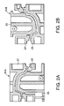
- FIGS. 2A and 2B are schematic cross-sectional views of the press molding die.
- FIGS. 3A and 3B are plan views of an engine hood for a vehicle being an example of a press molded product for the purpose of defining measure points of the amount of blank inflow when a grip section according to this invention is used and when a grip section being a comparative example from the prior art is used.
- FIG. 4 is a cross-sectional view of a bead forming portion of a vertical forming die according to the comparative example showing the dimensions and shape thereof.
- FIG. 5 is a diagram showing a computational model of the blank constraining force of a bead formed by the forming die according to this invention.
- FIG. 6 is a block diagram showing the steps in press molding according to this invention.
- FIG. 7 is a cross-sectional view of sheet metal blank for an engine hood before draw molding according to this invention.
- FIG. 8 is a cross-sectional view of an engine hood with the grip section detached by trimming according to this invention.
- FIG. 9 is a perspective view of a corner section of the grip section detached from the engine hood by trimming.
- FIG. 10 is a perspective view of a straight section of the grip section detached by trimming.
- a forming die according to this invention comprises an upper die 11 and a lower die 12 .
- the dies 11 and 12 grip a grip section W 2 of a blank W of sheet metal.
- the upper mold 11 and the lower mold 12 are opposed with a clearance therebetween corresponding to the thickness t of the blank W.
- the forming die is a die used in press molding an engine hood of a vehicle.
- the blank W comprises a product section W 1 which is the material to be press molded and a grip section W 2 disposed on the outer periphery of the product section W 1 .
- FIG. 1 corresponds to an enlarged view of the grip section W 2 of the left side of FIG. 7 .
- the product section W 1 is disposed on the right side of the figure and the left side of the figure corresponds to the outer periphery of the blank W.
- the grip section W 2 comprises bead W 3 and horizontal sections W 4 and W 5 disposed on either side of the bead W 3 .
- the bead W 3 comprises a groove A, a tongue B, a groove C and a tongue D provided alternately in order to form two interconnected letters S.
- the groove A and the tongue B are connected by a straight section 13 .
- the tongue B and the groove C are connected by a straight section 15 .
- the groove section C and the tongue D are connected by a straight section 14 .
- the straight section 15 is longer than the straight section 13 and the straight section 14 on either side.
- the upper die 11 of the forming die is provided with a horizontal face 11 A pressing the horizontal section W 5 , a first protruding corner 2 molding the grooved section A, a second indented corner 7 molding the tongue section B, a third tongue corner 4 forming a grooved section C, a fourth grooved corner 9 forming a tongue section D, and a horizontal face 11 B pressing the horizontal section W 4 .
- the lower die 12 of the forming die comprises a horizontal face 12 A pressing the horizontal section W 5 , a first indented corner 6 molding the grooved section A, a second protruding corner 3 molding the tongue section B, a third indented corner 8 forming a grooved section C, a fourth protruding corner 5 forming a tongue section D, and a horizontal face 12 B pressing the horizontal section W 4 .
- the height from the horizontal face 12 A disposed at the lowest position of the lower die 12 to the horizontal face 12 B disposed at the highest position is defined as “h”.
- the height from the horizontal face 11 A of the upper die 11 to the horizontal face 11 B is also defined as “h”.
- the bead W 3 is therefore formed within the range of the height h.
- a flat face 13 A corresponding to the straight section 13 of the blank W is formed between the first protruding corner 2 and the second indented corner 7 of the upper die 11 .
- a flat face 15 A corresponding to the straight section 15 of the blank W is formed between the second indented corner 7 and the third protruding corner 4 .
- a flat face 14 A corresponding to the straight section 14 of the blank W is formed between the third protruding corner 4 and the fourth indented corner 9 .
- a flat face 13 B corresponding to the straight section 13 of the blank W is formed between the first indented corner 6 and the second protruding corner 3 of the lower die 12 .
- a flat face 15 B corresponding to the straight section 15 of the blank W is formed, between the second protruding corner 3 and the third indented corner 8 .
- a flat face 14 B corresponding to the straight section 14 of the blank W is formed between the third indented corner 8 and the fourth protruding corner 5 .
- the slope of the straight section 13 is equal to the slope of the flat faces 13 A, 13 B.
- the slope of the straight section 14 is equal to the slope of the flat faces 14 A, 14 B.
- the slope of the straight section 15 is equal to the slope of the flat faces 15 A, 15 B.
- the radius of the first protruding corner 2 the radius of the second protruding corner 3 , the radius of the third protruding corner 4 , and the radius of the fourth protruding corner 5 are respectively designated as Ra, Rb, Rc and Rd.
- the angle of intersection of the flat face 13 B and the horizontal face 12 A of the lower die 12 is greater than or equal to 90 degrees.
- the angle of intersection of the flat face 14 B and the horizontal face 12 B of the lower die 12 is also greater than or equal to 90 degrees.
- the angle subtended by the slope of the straight section 13 and the vertical line in the figure is defined as ⁇ c.
- the flat faces 13 A, 13 B corresponding to the straight section 13 have the same slope as the straight section 13 .
- the angle subtended by the slope of the straight section 14 and the vertical line in the figure is defined as ⁇ d.
- the angle ⁇ c is also used as the value expressing the angle subtended by the first protruding corner 2 .
- the angle ⁇ d is also used as the value expressing the angle subtended by the fourth protruding corner 5 .
- the angle of intersection ⁇ a of the flat face 13 B corresponding to the straight section 13 and the flat face 15 B corresponding to the straight section 15 is smaller than 90 degrees.
- the angle of intersection ⁇ b of the flat face 15 B corresponding to the straight section 15 and the flat face 14 B corresponding to the straight section 14 is also smaller than 90 degrees.
- the upper die 11 and the lower die 12 described above are adapted for use with a single-action draw forming die 20 A shown in FIG. 2A or a double-action draw forming die 20 B shown in FIG. 2B .
- the single-action draw forming die 20 A in FIG. 2A uses the upper die 11 as an upper die 21 and the lower die 12 as a cushion ring 22 .
- the double-action draw forming die 20 B in FIG. 2B uses the upper die 11 as a blank holder 24 and the lower die 12 as a lower die 23 .
- the member 25 designates a punch.
- the blank W is placed at a predetermined position on the lower die 12 .
- the horizontal section W 4 of the blank W is supported by the highest horizontal face 12 B of the lower die 12 and the horizontal face 12 A, the first indented corner 6 , the second protruding corner 3 , the third indented corner 8 and the fourth protruding corner 5 of the lower die 12 are covered by the grip section W 2 of the blank W which is not yet molded.
- the upper die 11 is depressed downwardly until the horizontal face 11 A becomes in contact with the horizontal section W 5 of the blank W.
- the horizontal section W 5 presses downwardly on the horizontal face 11 A.
- the first protruding corner 2 and the third protruding corner 4 of the upper die 11 and the second protruding corner 3 and the fourth protruding corner 5 of the lower die 12 respectively abut with the blank W and create a bending deformation in the blank W.
- the molding of the bead W 3 is completed by depressing the upper die 11 to the state as shown in FIG. 1 .
- the molded bead W 3 is alternatively bent and deformed in opposite directions by the plurality of protruding corners 2 - 5 formed alternatively on the upper die 11 and the lower die 12 .
- the bead W 3 comprises a first deformed section wound onto the fourth protruding corner 5 positioned on the innermost periphery, a second deformed section wound onto the third protruding corner 4 on the outer side of the first deformed section, a third deformed section wound onto the second protruding corner 3 on the outer side of the second deformed section, and a deformed section wound onto the first protruding corner 2 on the outermost periphery.
- the clearance between the indented corners 6 - 9 and the corresponding indented corner 2 - 5 does not always have to equal the plate thickness t of the blank W. For example, even if the clearance is greater than the plate thickness t, there is a bending deformation wound onto each protruding corner 2 - 5 . As a result, the bead W 3 is restricted by the upper die 11 and the lower die 12 . It is even preferred that the clearance is set to be slightly greater than the plate thickness t.
- the bead W 3 on the right side of the blank W shown in FIG. 7 is restricted in the same manner by the upper die 11 and the lower die 12 .
- FIG. 8 shows the molded section W 1 A after the grip section W 2 is detached.
- FIG. 9 shows the shape of the corner section of the grip section W 2 after cutting.
- FIG. 10 shows the shape of the straight section of the grip section W 2 at the same time.
- the inventors have compared the molding of an engine hood using the blank W in which bead W 3 is formed and retained by the upper die 11 and the lower die 12 according to this invention with the molding of an engine hood using a blank according to a comparative example which has a bead 200 formed and retained according to the prior art.
- the shape and dimensions of the bead 200 are shown in FIG. 4 .
- Ten measurement points M 1 -M 10 were provided in order to measure the inflow amount of the respective blanks as shown in FIGS. 3A and 3B .
- the inflow amount of the blank during use of blank W according to this invention in which bead W 3 is formed and retained by the upper die 11 and the lower die 12 is lower than the inflow amount of the blank of the comparative example in which bead 200 which has the shape and dimensions as shown in FIG. 4 is formed and retained.
- blank W in which bead W 3 is formed and retained by the upper die 11 and the lower die 12 according to this invention has a greater constraining force.
- the respective constraining forces on the bead W 3 and the bead 200 can be theoretically calculated from the angle of bend ⁇ 1 - ⁇ n and the respective radii R 1 -Rn of the protruding corners in the model shown in FIG. 5 .
- the calculation result for the constraining force of the bead W 3 is 415 newtons/millimeters (N/mm) and the calculation result for the constraining force of the bead 200 is 363 (N/mm).
- the groove section A, the tongue section B, the groove section C, the tongue section D are alternately formed on the bead W 3 .
- the bead 200 of the prior art as shown in FIG. 4 is formed in the sequence of the groove section E, the tongue section F, the groove section G, the tongue section H. In other words, the bead 200 does not entail the alternate formation of the indented and protruding sections.
- This invention uses the upper die 11 and the lower die 12 to form bead W 3 with alternating groove and tongue sections. During pressing of the product section W 1 , the upper die 11 and the lower die 12 retain the bead W 3 . Thus it is possible to obtain a high constraining force with low blank inflow.
- the press processing of the engine hood W 1 A as shown in FIGS. 3A and 3B is a draw forming process which molds the entire shape of the product and which includes draw processing, bulging processing and bending processing.
- this type of press molded product is completed by a trimming step 31 and a re-strike step 32 following a draw forming step 30 which corresponds to the above draw forming process.
- the trimming step 31 the outer periphery not used in the product is cut off after the draw step 30 as shown in FIG. 8 .
- the re-strike step 32 sections not completely molded in the draw forming step 30 or small curved sections including flange molds on the edge are molded into a final shape.
- the completed product comprising the engine hood W 1 A is sub-assembled into the engine hood and transported along the assembly line where it is combined with the inner hood which is a strengthening member in order to assemble the engine hood. Furthermore scrap metal resulting from the trimming step 31 or the re-strike step 32 is transported on a conveyer 33 .
- markings on the scrap formed by the grip section W 2 during the trimming step 31 demonstrates the behavior of the blank during the drawing step 30 .
- markings include those produced by sliding or grinding of the upper die 11 and the bead W 3 or sliding and grinding of the lower die 12 and the bead W 3 .
- Examination of the scrap formed from the grip section W 2 shows that the state produced in the bead W 3 during the trimming step 31 extends along the entire periphery. Thus it is possible to determine whether or not the pressing conditions produced by the upper die 11 and the lower die 12 during the draw forming step 30 are suitable.
- the inventors have used a simulation in order to analyze the relationship between the constraining force on the bead W 3 and the radius Ra-Rd and the angles ⁇ a- ⁇ d with respect to the first protruding corner 2 and third protruding corner 4 formed in the upper die 11 and the second protruding corner 3 and fourth protruding corner 5 formed in the lower die 12 .
- the results of the simulation are shown in TABLE-2 through TABLE-5.
- the variation in the subtended angle ⁇ a of the second protruding corner 3 and the subtended angle ⁇ b of the third protruding corner 4 in TABLE-2 shows the effect on the constraining force [N/mm] and the blank length of the bead W 3 . More precisely, the length (mm) of the straight section 15 of the blank W and the constraining force (N/mm) and length (mm) of the blank forming the bead W 3 when the subtended angle ⁇ a and the subtended angle ⁇ b are increased from 30 degrees in 10 degree increments while holding the subtended angles ⁇ c and ⁇ d, the radii Ra-Rd and the height h in FIG. 1 constant.
- the subtended angles ⁇ c and ⁇ d are equal.
- the peripheral length and dragging force are maintained respectively to preferred values.
- the length of the straight section 15 takes a minus value which means that the straight section 15 can not be formed.
- the curve of the radius Rb with the curve of the radius Rc and the configuration in FIG. 1 can not be geometrically materialized.
- the length of the straight section 15 becomes positive only when the subtended angle ⁇ a and the subtended angle ⁇ b reach a value of 70 degrees.
- the blank length (mm) and constraining force (N/mm) of the bead W 3 also take optimal values.
- the optimal values for the subtended angle ⁇ a and the subtended angle ⁇ b also vary with respect to values such as the radii Rc and Rd and the height h.
- the lower limiting value taken by the subtended angle ⁇ a and the subtended angle ⁇ b is 30 degrees.
- the blank length (mm) of the bead W 3 takes a minus value and the constraining force (N/mm) also undergoes a conspicuous reduction.
- the constraining force (N/mm) in this case is expected to be equivalent to the force on the bead in the comparative example.
- the subtended angle ⁇ a and the subtended angle ⁇ b are set in the range from 30 degrees to 90 degrees in order to obtain a sufficient constraining force. Since the subtended angle ⁇ a and the subtended angle ⁇ b are acute in this range, the constraining force is large and the blank length of the bead W 3 stays within a preferable range, even when the radii Ra and Rb are large. When the radii Ra and Rb are large, it is possible to prevent scraping of galvanized section when the blank W comprises metal plate with a galvanized surface.
- TABLE-3 shows an effect of the variation in the radii Ra-Rd of the first protruding corner 2 second protruding corner 3 , third protruding corner 4 and fourth protruding corner 5 on the blank length and the constraining force of the bead W 3 .
- the length (mm) of the straight section 15 of the blank W, the constraining force (N/mm) and length (mm) of the blank forming the bead W 3 are specified when the radii Ra-Rd are increased from 0 mm in 0.5 mm increments while holding the subtended angles ⁇ a- ⁇ d, and the height h constant in FIG. 1 .
- the subtended angles ⁇ a- ⁇ d are equal.
- the optimal radius of curvature is considered to be within the range of 1 mm to 5 mm.
- the radii of curvature Ra-Rd were all set to the same value. However it is possible to set the radii of curvature Ra-Rd to different values. Setting the radii of curvature Ra-Rd to a suitable value makes it possible to prevent scraping of galvanized section when the blank W is sheet metal with a galvanized surface. Furthermore it is possible to obtain a preferred constraining force by selecting the radii of curvature Ra-Rd.
- TABLE-4 shows an effect of the variation in the subtended angle ⁇ c of the first protruding corner 2 and the subtended angle ⁇ d of the fourth protruding corner 5 on the constraining force [N/mm] and the blank length (mm) of the bead W 3 . More precisely, the length (mm) of the straight section 15 of the blank W and the constraining force (N/mm) and blank length (mm) of the bead W 3 are specified when the subtended angle ⁇ c and the subtended angle ⁇ d are increased from 0 degrees in 3 degree increments while holding the subtended angles ⁇ a and ⁇ b, the radii Ra-Rd and the height h in FIG. 1 constant.
- the subtended angles ⁇ c and ⁇ d are equal.
- the subtended angle ⁇ c is the angle between the vertical line and the straight section 13 as shown in FIG. 1 .
- the actual subtended angle of the first protruding corner 2 is a value obtained by adding 90 degrees to the subtended angle ⁇ c.
- the subtended angles ⁇ d is the angle between the vertical line and the straight section 14 as shown in FIG. 1 .
- the actual subtended angle of the fourth protruding corner 5 is a value obtained by adding 90 degrees to the subtended angle ⁇ d.
- the upper limiting value of the subtended angle ⁇ c and the subtended angle ⁇ d can be assumed to be 30 degrees.
- the limiting value is converted to the actual subtended angle of the first protruding corner 2 and the fourth protruding corner 5 , it takes a value of 90-120 degrees.
- the preferred range of the subtended angle ⁇ c and the subtended angle ⁇ d is in a range from 0 degrees to 10 degrees.
- the subtended angle ⁇ c and the subtended angle ⁇ d are set in response to the required constraining force.
- Table 5 shows the effect of the variation in the height h of the bead W 3 on the length (mm) of the straight section 15 and the blank length (mm) of the of the bead W 3 . More precisely, the length (mm) of the straight section 15 and the length (mm) of the blank forming the bead W 3 are specified when the height h is increased from 1 mm in 1 mm increments. Although the height h affects the constraining force, it is not possible to calculate the constraining force directly from the value for the height h.
- this invention forms protruding sections and indented sections alternatively on a bead W 3 .
- appropriate settings for the subtended angles ⁇ a- ⁇ d and the radii Ra-Rd of the protruding corners 2 - 5 of the upper die 11 and the lower die 12 used to form the protruding and indented sections ensure a sufficient constraining force on the bead W 3 . Furthermore this makes it possible to prevent scraping of galvanized sections when the blank W is sheet metal with a galvanized surface.
- scraping of the galvanized surface can be prevented by setting the radii Ra-Rd to a large value. It is possible to obtain a sufficient constraining force by setting the subtended angles ⁇ a- ⁇ d to within the geometrically permissible range. In particular, it is possible to obtain a sufficient constraining force even when the radii Ra-Rb are relatively large by setting the subtended angle ⁇ a of the second protruding corner 3 and the subtended angle ⁇ b of the third protruding corner 4 to a range of 30 degrees to 90 degrees.
- the constraining force can be ensured and cracking of the bead W 3 can be prevented by setting the radii of curvature Ra-Rd of the protruding corners 2 - 5 in a range from 1 mm to 5 mm. Furthermore in order to obtain the required constraining force, a wide range of values for the constraining force can be obtained by regulating the subtended angle of the first protruding corner 2 and the subtended angle of the fourth protruding corner 5 to a preferred range of 90-120 degrees.
- Tokugan 2004-376183 with a filing date of Dec. 27, 2004 in Japan
- Tokugan 2005-248915 with a filing date of Aug. 30, 2005 in Japan are hereby incorporated by reference.
- the bead W 3 comprises two alternatively disposed indented sections A, C and protruding sections B, D.
- this invention is not limited to the number of indented or protruding sections. In other words, it is possible to adapt the invention to cases in which the number of indented or protruding sections differs from the above embodiment.
Applications Claiming Priority (4)
| Application Number | Priority Date | Filing Date | Title |
|---|---|---|---|
| JP2004376183 | 2004-12-27 | ||
| JP2004-376183 | 2004-12-27 | ||
| JP2005248915 | 2005-08-30 | ||
| JP2005-248915 | 2005-08-30 |
Publications (2)
| Publication Number | Publication Date |
|---|---|
| US20060137422A1 US20060137422A1 (en) | 2006-06-29 |
| US7322222B2 true US7322222B2 (en) | 2008-01-29 |
Family
ID=36143219
Family Applications (1)
| Application Number | Title | Priority Date | Filing Date |
|---|---|---|---|
| US11/313,659 Expired - Fee Related US7322222B2 (en) | 2004-12-27 | 2005-12-22 | Method of press molding and molding device |
Country Status (6)
| Country | Link |
|---|---|
| US (1) | US7322222B2 (ja) |
| EP (1) | EP1674168B1 (ja) |
| JP (1) | JP4853007B2 (ja) |
| KR (1) | KR100650357B1 (ja) |
| CN (1) | CN100429014C (ja) |
| DE (1) | DE602005012917D1 (ja) |
Cited By (7)
| Publication number | Priority date | Publication date | Assignee | Title |
|---|---|---|---|---|
| US20080264138A1 (en) * | 2007-04-26 | 2008-10-30 | Jung Jin Woo | Bead forming unit for press |
| US20100139355A1 (en) * | 2006-11-24 | 2010-06-10 | Aramizu Teruo | Trimming press working apparatus |
| US9120137B2 (en) * | 2012-06-01 | 2015-09-01 | Fca Us Llc | Stamping apparatus and method of use |
| US20150273559A1 (en) * | 2012-11-30 | 2015-10-01 | Toyota Jidosha Kabushiki Kaisha | Method for working steel sheet, and apparatus for working steel sheet |
| US20170001232A1 (en) * | 2013-12-26 | 2017-01-05 | Nippon Steel & Sumitomo Metal Corporation | Manufacturing apparatus and manufacturing method for stretch-formed product |
| US9827606B2 (en) * | 2015-12-04 | 2017-11-28 | Fca Us Llc | Stamping apparatus having flared bead |
| US11020785B2 (en) * | 2015-07-06 | 2021-06-01 | Nippon Steel Corporation | Method and apparatus for manufacturing press component |
Families Citing this family (18)
| Publication number | Priority date | Publication date | Assignee | Title |
|---|---|---|---|---|
| CA2685334C (en) * | 2009-10-30 | 2013-03-12 | Honda Motor Co., Ltd. | Scrap shape retention |
| CA2695101C (en) | 2010-03-01 | 2012-10-16 | Honda Motor Co., Ltd. | Reducing waste in metal stamping processes and systems therefor |
| JP5500326B1 (ja) * | 2012-06-07 | 2014-05-21 | 東洋製罐株式会社 | 深絞り成形方法 |
| MX341852B (es) * | 2012-12-26 | 2016-09-05 | Nissan Motor | Metodo de formacion por embuticion. |
| JP5920280B2 (ja) * | 2013-04-24 | 2016-05-18 | Jfeスチール株式会社 | 自動車外板部品の成形方法 |
| FR3007302B1 (fr) * | 2013-06-19 | 2015-06-26 | Peugeot Citroen Automobiles Sa | Cavite de degagement pour un jonc de retenue dans un outillage d'emboutissage |
| CN103434142B (zh) * | 2013-08-30 | 2016-05-04 | 上海飞机制造有限公司 | 制造复合材料型材的方法和模具 |
| JP6024636B2 (ja) * | 2013-09-30 | 2016-11-16 | Jfeスチール株式会社 | プレス成形金型 |
| CN105921615B (zh) * | 2016-04-20 | 2018-07-13 | 江苏集鑫成精密工业有限公司 | 一种大型电视机背板成型模具 |
| FR3056127B1 (fr) * | 2016-09-16 | 2019-04-19 | Peugeot Citroen Automobiles Sa | Dispositif d’emboutissage d’un flan de tole permettant une faible profondeur d’emboutissage d’un jonc |
| JP2018058077A (ja) * | 2016-10-03 | 2018-04-12 | トヨタ車体株式会社 | プレス用金型 |
| JP7045869B2 (ja) * | 2018-01-31 | 2022-04-01 | ダイハツ工業株式会社 | プレス成形機 |
| US20190255587A1 (en) * | 2018-02-20 | 2019-08-22 | GM Global Technology Operations LLC | Stamped component with improved formability |
| JP6648867B1 (ja) * | 2018-05-24 | 2020-02-14 | Jfeスチール株式会社 | プレス部品の製造方法 |
| CN115996799A (zh) * | 2020-09-02 | 2023-04-21 | 杰富意钢铁株式会社 | 冲压部件的制造方法、模具的设计方法、模具形状设计装置以及模具 |
| JP7276307B2 (ja) * | 2020-11-18 | 2023-05-18 | Jfeスチール株式会社 | プレス成形方法及びプレス成形金型 |
| CN113414292B (zh) * | 2021-08-24 | 2022-01-11 | 宁波明讯实业有限公司 | 一种新能源汽车电池包上盖的冲压检测方法 |
| CN113414293B (zh) * | 2021-08-24 | 2022-01-11 | 宁波明讯实业有限公司 | 一种新能源汽车电池包上盖的冲压系统 |
Citations (12)
| Publication number | Priority date | Publication date | Assignee | Title |
|---|---|---|---|---|
| US3664172A (en) * | 1970-06-01 | 1972-05-23 | Reynolds Metals Co | Apparatus for and method of forming cup-shaped articles |
| US4096729A (en) * | 1977-05-31 | 1978-06-27 | General Motors Corporation | Sheet metal draw die apparatus |
| JPS56160836A (en) * | 1980-05-13 | 1981-12-10 | Nissan Motor Co Ltd | Pressure die for drawing |
| JPS63177926A (ja) | 1987-01-17 | 1988-07-22 | Honda Motor Co Ltd | 絞り金型 |
| JPH0366423A (ja) * | 1989-08-01 | 1991-03-22 | Toyota Auto Body Co Ltd | 深絞り成形方法及びその絞りプレス型 |
| US5014537A (en) * | 1990-06-13 | 1991-05-14 | General Motors Corporation | Convertible lockbead-drawbead |
| DE19504264A1 (de) | 1995-02-09 | 1996-08-14 | Daimler Benz Ag | Verfahren und Vorrichtung für Ziehwerkzeuge |
| US5701777A (en) * | 1995-07-24 | 1997-12-30 | Toyota Jidosha Kabushiki Kaisha | Drawing method and apparatus |
| JPH105889A (ja) | 1996-06-26 | 1998-01-13 | Toyota Motor Corp | ビード成形方法および成形型 |
| US6196043B1 (en) * | 1999-08-27 | 2001-03-06 | General Motors Corporation | Double vee lockbead for sheet metal forming |
| JP2003164922A (ja) | 2001-12-03 | 2003-06-10 | Toyota Motor Corp | プレス型 |
| DE10322272A1 (de) | 2003-05-16 | 2004-12-02 | Nothelfer Gmbh | Verfahren zum Tiefziehen von Blechen und Tiefziehwerkzeug zur Anwendung bei diesem Verfahren |
Family Cites Families (4)
| Publication number | Priority date | Publication date | Assignee | Title |
|---|---|---|---|---|
| JP3404967B2 (ja) * | 1995-03-09 | 2003-05-12 | トヨタ自動車株式会社 | 絞り成形方法 |
| JP3547862B2 (ja) * | 1995-09-08 | 2004-07-28 | 本田技研工業株式会社 | 折曲フランジを有する絞り成形品の成形方法 |
| JPH09182920A (ja) * | 1995-12-28 | 1997-07-15 | Honda Motor Co Ltd | プレス金型 |
| JP4320727B2 (ja) | 2004-03-08 | 2009-08-26 | カルソニックカンセイ株式会社 | 気体圧縮機 |
-
2005
- 2005-12-13 JP JP2005359011A patent/JP4853007B2/ja not_active Expired - Fee Related
- 2005-12-19 KR KR1020050125559A patent/KR100650357B1/ko not_active IP Right Cessation
- 2005-12-22 DE DE602005012917T patent/DE602005012917D1/de active Active
- 2005-12-22 US US11/313,659 patent/US7322222B2/en not_active Expired - Fee Related
- 2005-12-22 EP EP05028206A patent/EP1674168B1/en not_active Expired - Fee Related
- 2005-12-27 CN CNB2005101352189A patent/CN100429014C/zh not_active Expired - Fee Related
Patent Citations (12)
| Publication number | Priority date | Publication date | Assignee | Title |
|---|---|---|---|---|
| US3664172A (en) * | 1970-06-01 | 1972-05-23 | Reynolds Metals Co | Apparatus for and method of forming cup-shaped articles |
| US4096729A (en) * | 1977-05-31 | 1978-06-27 | General Motors Corporation | Sheet metal draw die apparatus |
| JPS56160836A (en) * | 1980-05-13 | 1981-12-10 | Nissan Motor Co Ltd | Pressure die for drawing |
| JPS63177926A (ja) | 1987-01-17 | 1988-07-22 | Honda Motor Co Ltd | 絞り金型 |
| JPH0366423A (ja) * | 1989-08-01 | 1991-03-22 | Toyota Auto Body Co Ltd | 深絞り成形方法及びその絞りプレス型 |
| US5014537A (en) * | 1990-06-13 | 1991-05-14 | General Motors Corporation | Convertible lockbead-drawbead |
| DE19504264A1 (de) | 1995-02-09 | 1996-08-14 | Daimler Benz Ag | Verfahren und Vorrichtung für Ziehwerkzeuge |
| US5701777A (en) * | 1995-07-24 | 1997-12-30 | Toyota Jidosha Kabushiki Kaisha | Drawing method and apparatus |
| JPH105889A (ja) | 1996-06-26 | 1998-01-13 | Toyota Motor Corp | ビード成形方法および成形型 |
| US6196043B1 (en) * | 1999-08-27 | 2001-03-06 | General Motors Corporation | Double vee lockbead for sheet metal forming |
| JP2003164922A (ja) | 2001-12-03 | 2003-06-10 | Toyota Motor Corp | プレス型 |
| DE10322272A1 (de) | 2003-05-16 | 2004-12-02 | Nothelfer Gmbh | Verfahren zum Tiefziehen von Blechen und Tiefziehwerkzeug zur Anwendung bei diesem Verfahren |
Cited By (10)
| Publication number | Priority date | Publication date | Assignee | Title |
|---|---|---|---|---|
| US20100139355A1 (en) * | 2006-11-24 | 2010-06-10 | Aramizu Teruo | Trimming press working apparatus |
| US8291739B2 (en) * | 2006-11-24 | 2012-10-23 | Oiles Corporation | Trimming press working apparatus |
| US20080264138A1 (en) * | 2007-04-26 | 2008-10-30 | Jung Jin Woo | Bead forming unit for press |
| US9120137B2 (en) * | 2012-06-01 | 2015-09-01 | Fca Us Llc | Stamping apparatus and method of use |
| US20150273559A1 (en) * | 2012-11-30 | 2015-10-01 | Toyota Jidosha Kabushiki Kaisha | Method for working steel sheet, and apparatus for working steel sheet |
| US9687900B2 (en) * | 2012-11-30 | 2017-06-27 | Toyota Jidosha Kabushiki Kaisha | Method for working steel sheet, and apparatus for working steel sheet |
| US20170001232A1 (en) * | 2013-12-26 | 2017-01-05 | Nippon Steel & Sumitomo Metal Corporation | Manufacturing apparatus and manufacturing method for stretch-formed product |
| US10071410B2 (en) * | 2013-12-26 | 2018-09-11 | Nippon Steel & Sumitomo Metal Corporation | Manufacturing apparatus and manufacturing method for stretch-formed product |
| US11020785B2 (en) * | 2015-07-06 | 2021-06-01 | Nippon Steel Corporation | Method and apparatus for manufacturing press component |
| US9827606B2 (en) * | 2015-12-04 | 2017-11-28 | Fca Us Llc | Stamping apparatus having flared bead |
Also Published As
| Publication number | Publication date |
|---|---|
| KR100650357B1 (ko) | 2006-11-28 |
| CN1796018A (zh) | 2006-07-05 |
| EP1674168B1 (en) | 2009-02-25 |
| JP2007090426A (ja) | 2007-04-12 |
| KR20060074836A (ko) | 2006-07-03 |
| JP4853007B2 (ja) | 2012-01-11 |
| EP1674168A1 (en) | 2006-06-28 |
| CN100429014C (zh) | 2008-10-29 |
| DE602005012917D1 (de) | 2009-04-09 |
| US20060137422A1 (en) | 2006-06-29 |
Similar Documents
| Publication | Publication Date | Title |
|---|---|---|
| US7322222B2 (en) | Method of press molding and molding device | |
| JP4693475B2 (ja) | プレス成形方法およびそれに用いる金型 | |
| US7130708B2 (en) | Draw-in map for stamping die tryout | |
| CN111867747B (zh) | 冲压成型用的金属板、冲压成型装置和冲压部件的制造方法 | |
| JP2977071B2 (ja) | 絞り成形方法および絞り成形型 | |
| JP6738055B2 (ja) | プレス成形品の設計方法、プレス成形金型、プレス成形品およびプレス成形品の製造方法 | |
| CN111836689B (zh) | 冲压部件的制造方法、冲压成型装置以及冲压成型用的金属板 | |
| JP7302747B2 (ja) | プレス成形品の製造方法及びプレス成形装置 | |
| KR101834850B1 (ko) | 프레스 성형 방법, 및 프레스 성형 부품의 제조 방법 | |
| JP7364905B2 (ja) | 板金成形品の製造方法、板金成形品の製造装置、及びフランジアップ工具 | |
| JP7070287B2 (ja) | プレス成形部品の製造方法、及びプレス成形部品 | |
| JP2021164954A (ja) | プレス部品の製造方法、曲げ戻し用の金型、プレス部品の成形方法及び高強度鋼板 | |
| WO2020105647A1 (ja) | 湾曲部材の製造方法 | |
| JPH03268823A (ja) | 薄板金属素材から延伸不能な形状体の一部を製造する方法及びその方法により製造される部品 | |
| JP3680260B2 (ja) | 絞り加工装置 | |
| JP3931736B2 (ja) | プレス成形型 | |
| JP7341840B2 (ja) | 自動車用パネルの製造方法 | |
| JP7246227B2 (ja) | プレス成形方法及び金属板 | |
| JP7350607B2 (ja) | 自動車用パネルの製造方法 | |
| JP7359707B2 (ja) | プレス成形品の製造方法、及びプレス成形品の製造装置 | |
| JP5225019B2 (ja) | サイプブレードの製造方法および製造用金型 | |
| JP2003311339A (ja) | プレス成形品、プレス成形品の製造方法および製造装置 | |
| JP2024034692A (ja) | 板金部材成形方法および成形部品 | |
| WO2018012406A1 (ja) | プレス品製造方法 | |
| CN117840339A (zh) | 冲压成型方法 |
Legal Events
| Date | Code | Title | Description |
|---|---|---|---|
| AS | Assignment |
Owner name: NISSAN MOTOR CO., LTD., JAPAN Free format text: ASSIGNMENT OF ASSIGNORS INTEREST;ASSIGNORS:KODAKA, HIDEMOTO;ADACHI, NAOHISA;REEL/FRAME:017361/0605 Effective date: 20051110 |
|
| FEPP | Fee payment procedure |
Free format text: PAYOR NUMBER ASSIGNED (ORIGINAL EVENT CODE: ASPN); ENTITY STATUS OF PATENT OWNER: LARGE ENTITY |
|
| FPAY | Fee payment |
Year of fee payment: 4 |
|
| REMI | Maintenance fee reminder mailed | ||
| LAPS | Lapse for failure to pay maintenance fees | ||
| STCH | Information on status: patent discontinuation |
Free format text: PATENT EXPIRED DUE TO NONPAYMENT OF MAINTENANCE FEES UNDER 37 CFR 1.362 |
|
| FP | Lapsed due to failure to pay maintenance fee |
Effective date: 20160129 |