US7284635B2 - Electric power steering device - Google Patents
Electric power steering device Download PDFInfo
- Publication number
- US7284635B2 US7284635B2 US10/512,999 US51299904A US7284635B2 US 7284635 B2 US7284635 B2 US 7284635B2 US 51299904 A US51299904 A US 51299904A US 7284635 B2 US7284635 B2 US 7284635B2
- Authority
- US
- United States
- Prior art keywords
- vehicle
- steering
- shaft
- output shaft
- sided
- Prior art date
- Legal status (The legal status is an assumption and is not a legal conclusion. Google has not performed a legal analysis and makes no representation as to the accuracy of the status listed.)
- Expired - Lifetime, expires
Links
- 238000001514 detection method Methods 0.000 claims abstract description 10
- 230000002093 peripheral effect Effects 0.000 description 15
- 238000009499 grossing Methods 0.000 description 5
- XEEYBQQBJWHFJM-UHFFFAOYSA-N Iron Chemical compound [Fe] XEEYBQQBJWHFJM-UHFFFAOYSA-N 0.000 description 4
- 238000010273 cold forging Methods 0.000 description 4
- 239000000696 magnetic material Substances 0.000 description 3
- XAGFODPZIPBFFR-UHFFFAOYSA-N aluminium Chemical compound [Al] XAGFODPZIPBFFR-UHFFFAOYSA-N 0.000 description 2
- 229910052782 aluminium Inorganic materials 0.000 description 2
- 238000010276 construction Methods 0.000 description 2
- 230000001276 controlling effect Effects 0.000 description 2
- 229910052742 iron Inorganic materials 0.000 description 2
- 230000007935 neutral effect Effects 0.000 description 2
- 238000007669 thermal treatment Methods 0.000 description 2
- 230000007423 decrease Effects 0.000 description 1
- 230000003247 decreasing effect Effects 0.000 description 1
- 238000006073 displacement reaction Methods 0.000 description 1
- 238000004519 manufacturing process Methods 0.000 description 1
- 239000000463 material Substances 0.000 description 1
- 230000010355 oscillation Effects 0.000 description 1
- 230000001105 regulatory effect Effects 0.000 description 1
Images


Classifications
-
- B—PERFORMING OPERATIONS; TRANSPORTING
- B62—LAND VEHICLES FOR TRAVELLING OTHERWISE THAN ON RAILS
- B62D—MOTOR VEHICLES; TRAILERS
- B62D5/00—Power-assisted or power-driven steering
- B62D5/04—Power-assisted or power-driven steering electrical, e.g. using an electric servo-motor connected to, or forming part of, the steering gear
- B62D5/0409—Electric motor acting on the steering column
-
- B—PERFORMING OPERATIONS; TRANSPORTING
- B62—LAND VEHICLES FOR TRAVELLING OTHERWISE THAN ON RAILS
- B62D—MOTOR VEHICLES; TRAILERS
- B62D5/00—Power-assisted or power-driven steering
- B62D5/04—Power-assisted or power-driven steering electrical, e.g. using an electric servo-motor connected to, or forming part of, the steering gear
- B62D5/0442—Conversion of rotational into longitudinal movement
- B62D5/0454—Worm gears
Definitions
- the present invention relates to an electric power steering apparatus contrived to reduce a length in an axial direction.
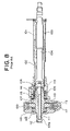
- a lower column 102 is fitted in a vehicle-front-sided portion of an upper column 101 of a steering column, and an upper shaft 103 and a lower shaft (input shaft) 104 of a steering shaft that are spline-fitted to each other are rotatably supported in these columns 101 and 102 .
- An output shaft 105 is connected via a stopper portion 106 to a vehicle-front-sided portion of the lower shaft (input shaft) 104 .
- a steering gear (unillustrated) is connected via a universal joint (unillustrated), etc. to a vehicle-front-sided portion of this output shaft 105 .
- the output shaft 105 is supported in housing 109 and in housing 110 through a pair of bearings 107 , 108 .
- a proximal end of a torsion bar 111 is fixedly press-fitted in a vehicle-front-sided portion of the lower shaft (input shaft) 104 .
- This torsion bar 111 extends through an interior of the hollowed output shaft 105 , and its front end is fixed to an end portion of the output shaft 105 by a fixing pin 112 .
- Torque detection grooves 113 are formed in the vehicle-rear-sided portion of the output shaft 105 .
- a sleeve 114 of a torque sensor is disposed outwards in a radial direction of these grooves 113 .
- a vehicle rear-sided end portion of this sleeve 114 is fixed to the vehicle-front-sided end portion of the lower shaft (input shaft) 104 by caulking or the like.
- Coils 115 , a board, etc. are provided outwards in a radial direction of the sleeve 114 .
- the output shaft 105 is fitted with a worm wheel 118 meshing with a worm 117 defined as a drive shaft of an electric motor 116 .
- a steering force generated when a driver steers the steering wheel is transferred to unillustrated steered travelling wheels via the input shaft 104 , the torsion bar 111 , the output shaft 105 and a rack-and-pinion steering gear device. Further, a rotational force of the electric motor 116 is transferred to the output shaft 105 via the worm 117 and the worm wheel 118 . An adequate amount of steering auxiliary torque can be applied to the output shaft 105 by properly controlling the rotational force and a rotational direction of the electric motor 116 .
- the sleeve 114 takes a structure that the vehicle rear-sided portion of the sleeve 114 is fixed to the vehicle front-sided end portion of the lower shaft (input shaft) 104 , and hence axis-directional lengths of the housing 109 and of the housing 110 for the electric power steering are comparatively taken long.
- the axis-directional lengths of the housing 109 and of the housing 110 specify a collapse/stroke quantity of the upper column 101 when a secondary collision of the vehicle happens. Therefore, the collapse/stroke quantity can not be increased over the stroke quantity shown in FIG. 8 in spite of a demand for increasing this stroke quantity.
- the steering auxiliary torque of the electric motor 116 is applied to the output shaft 105 via the worm wheel 118 , and consequently larger torsional torque than on the input shaft 104 disposed on the rear side of the vehicle occurs on this output shaft 105 when in a steady state.
- the worm wheel 118 has motor inertia that increases with a square of a gear ratio, and hence the extremely large impact torsional torque occurs on the output shaft 105 .
- the electric power steering apparatus has the hollowed structure that the torsion bar 111 extends through within the output shaft 105 , and the torsion bar 111 is fixedly press-fitted in the end portion of the output shaft 105 .
- a small-diameter portion 105 a of the output shaft 105 connected to a universal joint of the steering gear is twisted by the aforementioned torsional torque to an extremely slight degree in excess of an elasticity limit, its torsion (rotation) is detected by a torque sensor and appears to be an output deviation of the torque sensor, wherein this output deviation might induce self-steering. It is therefore required that strength of the small-diameter portion 105 a of the output shaft 105 be improved by effecting a thermal treatment upon this small-diameter portion 105 a.
- an electric power steering apparatus comprises a steering shaft including an input shaft connected to a steering wheel, an output shaft connected to a steering gear device, a torsion bar for transferring torque to the output shaft from the input shaft, the steering shaft being rotatably supported in a steering column through bearings respectively at a vehicle-rear-sided portion and a vehicle-front-sided portion, torque detection coils disposed apart outwards in a radial direction of the steering shaft, and a worm wheel meshing with a worm rotationally driven by a motor driven corresponding to detected torque and fixed to the output shaft in terms of its rotation, wherein the vehicle-front-sided bearing is constructed of a first bearing provided between a column-sided member and a vehicle-rear-sided portion of the worm wheel, and of a second bearing for supporting the steering shaft on a more front side than the worm wheel.
- the worm wheel is provided with a boss protruding towards the rear of a vehicle, the bearing is supported on an outer periphery of the boss, a vehicle-front-sided end portion of the sleeve extending in an axial direction so as to encompass an outer periphery of the steering shaft inwards in the radial direction of the boss, is fixed to the output shaft, and the torque detection coils are supported on the sleeve.
- the axis-directional length of the housing of the electric power steering can be reduced, whereby there can be increased the collapse/stroke quantity when the secondary collision of the vehicle happens.
- the input shaft is formed with a hollowed portion opened in the front of the vehicle, having its front side end provided inwards in the radial direction of the boss of the worm wheel and extending in the axial direction, and the torsion bar extends in the axial direction within the hollowed portion.
- a vehicle-front-sided end portion of the torsion bar is fixed to a vehicle-rear-sided end portion of the output shaft, and the vehicle-rear-sided end portion of the torsion bar is fixed to the input shaft by use of a pin.
- an outer periphery of the input shaft is formed with grooves that face the torque detection coils.
- the sleeve is formed with windows that face the coils.
- FIG. 1 is a vertical sectional view of an electric power steering apparatus according to a first embodiment of the present invention
- FIG. 2 is an enlarged sectional view of a principal portion of the electric power steering apparatus illustrated in FIG. 1 ;
- FIG. 3 is a partially cut-off perspective view of a torque sensor
- FIG. 4 is an exploded perspective view of the torque sensor
- FIG. 5A is a sectional view of the torque sensor
- FIG. 5B is a sectional view taken along the line b-b in FIG. 5A ;
- FIG. 6 is a vertical sectional view of the electric power steering apparatus according to a second embodiment of the present invention.
- FIG. 7 is an enlarged sectional view of a principal portion of the electric power steering apparatus illustrated in FIG. 6 ;
- FIG. 8 is a vertical sectional view of an electric power steering apparatus according to the prior art.
- FIG. 1 is a vertical sectional view of the electric power steering apparatus according to a first embodiment of the present invention.
- FIG. 2 is an enlarged sectional view of a principal portion of the electric power steering apparatus illustrated in FIG. 1 .
- FIG. 3 is a partially cut-off perspective view of a torque sensor.
- FIG. 4 is an exploded perspective view of the torque sensor.
- FIG. 5A is a sectional view of the torque sensor.
- FIG. 5B is a sectional view taken along the line b-b in FIG. 5A .
- a lower column 2 is fitted in a portion, on the front side of a vehicle, of an upper column 1 of a steering column, and a steering shaft is, through a bearing 100 on the rear side of the vehicle, supported rotatably via bearings 7 , 8 on the front side of the vehicle as will be mentioned later on.
- the steering shaft is constructed of an upper shaft 3 , a lower shaft 4 (input shaft) that are spline-fitted to each other, an output shaft 5 which will be described later on, a torsion bar 11 connected between the lower shaft 4 (input shaft) and the output shaft 5 , and so on.
- a portion, on the rear side of the vehicle, of the output shaft 5 is connected to a portion, on the front side of the vehicle, of the lower shaft (input shaft) 4 via a stopper portion 6 as will be explained later on.
- a steering gear (unillustrated) is connected via a universal joint (not shown) to the vehicle-front-sided portion of the output shaft 5 .
- the input shaft 4 is made of a magnetic material such as iron, etc.
- Housing is integral with the columns 1 , 2 and constitutes a column-sided member.
- a proximal side end of the torsion bar 11 is fixedly press-fitted to the vehicle-rear-sided portion of the output shaft 5 .
- the torsion bar 11 extends through an interior of the hollowed lower shaft (input shaft) 4 , and an end which is a vehicle-rear-sided end portion, of the torsion bar 11 is fixed to an end portion of the lower shaft (input shaft) 4 by use of fixing pin 12 .
- the fixing pin 12 is disposed in the hollowed upper shaft 3 and, with this contrivance, can be prevented from being removed. It should be noted that the torsion bar 11 is disposed closer to the rear side of the vehicle than a position of a worm wheel 18 .
- Grooves 13 for detecting torque are formed in a vehicle-front-sided portion of the lower shaft (input shaft) 4 , and a sleeve 14 of the torque sensor is disposed outwards in radial directions of these grooves 13 .
- a vehicle-front-sided end portion 14 a thereof is fixed to the vehicle-rear-sided end portion of the output shaft 5 by caulking or the like.
- a coil 15 for detecting the torque and a board are provided outwards in the radial direction of the sleeve 14 .
- the worm wheel 18 meshing with a worm 17 defined as a drive shaft of an electric motor 16 is fixedly fitted to the output shaft 5 .
- a steering force generated when a driver steers the steering wheel (unillustrated) attached to a rear side end of the upper shaft 3 is transferred to unillustrated steered travelling wheels via the input shaft 4 , the torsion bar 11 , the output shaft 5 and a rack-and-pinion steering gear. Further, a rotational force of the electric motor 16 is transferred to the output shaft 5 via the worm 17 and the worm wheel 18 meshing with the worm 17 . An adequate amount of steering auxiliary torque can be applied to the output shaft 5 by properly controlling the rotational force of the electric motor 16 and a rotational direction of meshing therewith.
- the worm wheel 18 is formed integrally with a concentric cylindrical boss portion 18 a protruding towards the rear side of the vehicle.
- the bearings 7 , 8 are disposed at the vehicle-rear-and-front-sided portions of the worm wheel 18 .
- the bearing 7 provided at the vehicle-rear-sided portion is supported on an outer periphery of the boss portion 18 a of the worm wheel 18 , and is disposed between the outer periphery of the boss portion and a housing member 9 .
- the vehicle-front-sided end portion 14 a of the sleeve 14 is fixedly fitted on the vehicle-rear-sided end portion of the output shaft 5 inwardly in the radial direction of the boss portion 18 a of the worm wheel 18 . It is therefore possible to reduce a length of the housing in the axial direction, which is constructed of the housing member 9 and a housing member 10 . This lengthwise reduction thereof makes it feasible to increase a collapse/stroke quantity when a secondary collision of the vehicle happens.
- the vehicle-front-sided bearing 8 of the worm wheel 18 is provided adjacent to the worm wheel 18 between the output shaft 5 and the housing member 10 .
- the torsion bar 11 is disposed at the vehicle-rear-sided portion of the worm wheel 18 , wherein large torsional torque does not occur both when in a steady state and when in a reverse input, thereby enabling safety to be improved with no possibility of causing a deviation in output of the torque sensor and enabling the cost to be decreased because of necessitating none of a thermal treatment.
- a large-diameter portion 4 A coaxial with the input shaft 4 is formed on an outer peripheral surface of the vehicle-front-sided portion of the input shaft 4 , and the aforementioned thin sleeve 14 is so disposed in close proximity to the outer peripheral surface of the large-diameter portion 4 A as to embrace this large-diameter portion 4 A.
- the sleeve 14 is made of a conductive but non-magnetic material (e.g., aluminum), and a vehicle-front-sided end portion of the sleeve 14 is fixed to the vehicle-rear-sided end portion of the output shaft 5 .
- a conductive but non-magnetic material e.g., aluminum
- a large-diameter portion 5 A is formed on the vehicle-rear-sided end portion of the output shaft 5 , and an outer peripheral surface of this large-diameter portion 5 A is formed with a plurality of axis-directional grooves 21 (four lines of grooves are provided in this example) extending in the axial direction and with a periphery-directional groove 22 continuous in a peripheral direction.
- the respective axis-directional grooves 21 are so formed extending over the entire length of the large-diameter portion 5 A as to be apart from each other at equal intervals (90 degrees) in the peripheral direction. Further, the periphery-directional groove 22 is formed in the vicinity of where the end portion 14 a of the sleeve 14 is positioned when fixing the sleeve 14 .
- a plurality of semi-spherical protrusions 23 are formed inwards in the radial direction (four pieces are provided in this embodiment) in positions slightly receded from an end portion of the sleeve 14 .
- the number and forming positions of these protrusions 23 correspond to the axis-directional grooves 21 of the output shaft 5 , and therefore the protrusions 23 are disposed apart from each other at the equal intervals (90 degrees) in the peripheral direction. Further, a height of the protrusion 23 is much the same as a depth of the axis-directional groove 21 .
- the protrusions 23 are fitted in the axis-directional grooves 21 , thereby positioning the sleeve 14 with respect to the output shaft in the peripheral direction. Then, the sleeve 14 is intruded in the axial direction, the end portion of the sleeve 14 is set in close proximity to the periphery-directional groove 22 . In this state, the end portion of the sleeve 14 is caulked inwards and thus gets bitten in the periphery-directional groove 22 .
- the periphery-directional position of the sleeve 14 with respect to the output shaft 5 is fixed by fitting the protrusions 23 in the axis-directional grooves 21 .
- the axis-directional position of the sleeve 14 with respect to the output shaft 5 is fixed by getting the end portion 14 a thereof bitten in the periphery-directional groove 22 .
- a spline hole 5 B is, as shown in FIG. 5A , coaxially formed in the vehicle-rear-sided end portion of the output shaft 5 , whereby the vehicle rear-sided end portion of the torsion bar 11 is fixedly held through spline-connection.
- a female stopper 24 (a stopper portion 6 ) is formed in an inner peripheral surface of the cylindrical large-diameter portion 5 A closer to the end surface than the spline hole 5 B.
- the female stopper 24 is a hole including eight pieces of recessed portions 24 A formed such that the inner peripheral surface is recessed (in eight positions) outwards in the radial direction.
- a male stopper 25 (a stopper portion 6 ) is formed, corresponding to the female stopper 24 , on an end portion of the input shaft 4 .
- the male stopper 25 is a shaft having eight pieces of protruded portions 25 A formed such that the outer peripheral surface is protruded (in eight positions) outwards in the radial direction, wherein a periphery-directional width of each protruded portion 25 A is slightly smaller than a periphery-directional width of the recessed portion 24 A.
- a portion of the sleeve 14 that embraces the large-diameter portion 4 A of the input shaft 4 after assembling the sleeve 14 is formed with a plurality of rectangular windows 30 a spaced away from each other at equal intervals in the peripheral direction on a remote side from the protrusions 23 , and with a plurality of rectangular windows 30 b spaced away from each other at equal intervals in the peripheral direction on a close side to the protrusions 23 so as to shift in phase at 180 degrees from the windows 30 a , . . . , 30 a (to describe it at an actual angle, the windows 30 b are shifted in phase at (360/n ⁇ 1 ⁇ 2) degrees from n-pieces of windows 30 a ).
- the large-diameter portion 4 A of the input shaft 4 has a plurality of grooves 13 formed at equal intervals extending in the axial direction.
- the number of the grooves 13 is, however, the same as the number of the windows 30 a and the number of the windows 30 b.
- the input shaft 4 and the sleeve 14 are positioned so that a phase between the center of each groove 13 in a widthwise direction and a center of the window 30 a in the widthwise direction is 90 degrees and so that a phase between the center of each groove 13 in the widthwise direction and a center of the window 30 b in the widthwise direction is 90 degrees in the opposite direction (to describe it at an actual angle, they are positioned so that there is made an angle of (360/n ⁇ 1 ⁇ 4) degrees to the center of each of n-pieces of grooves 13 in the widthwise direction).
- the phases of the input shaft 4 and the sleeve 14 be adjusted so that overlapped states between the grooves 13 and the windows 30 a and between the grooves 13 and the windows 30 b become as described above.
- the sleeve 14 is fixed to the output shaft 5 , and the input shaft 4 and the output shaft 5 are connected to each other through the torsion bar 11 .
- a phase relationship between the respective portions is determined as follows.
- the male stopper 25 formed on the input shaft 4 and the female stopper 24 formed in the output shaft 5 are engaged in a neutral position, i.e., the protruded portion 25 A may be positioned in a central portion of the recessed portion 24 A. Therefore, a periphery-directional position of each protruded portion 25 A of the male stopper 25 is set as a fiducial position when considering the phases of the respective portions of the input shaft 4 , and a periphery-directional position of each recessed portion 24 A of the female stopper 24 is set as a fiducial position when considering the phases of the respective portions of the output shaft 5 .
- the periphery-directional positions of the grooves 13 , . . . , 13 formed in the large-diameter portion 4 A are determined based on the protruded portions 25 A.
- the periphery-directional positions of the axis-directional grooves 21 , . . . , 21 formed in the outer peripheral surface of the large-diameter portion 5 A are determined based on the recessed portions 24 A.
- the periphery-directional positions of the respective windows 30 a , . . . , 30 a and 30 b , . . . , 30 b are determined based on the protrusions 23 .
- the phase relationship between the grooves 13 , . . . , 13 and the windows 30 a , . . . , 30 and 30 b , . . . , 30 b is established as described above by performing the neutral alignment of the stoppers even if the phase adjustment of the sleeve 14 is not particularly conducted on the occasion of assembling.
- the grooves 13 and the male stopper 25 are formed by cold forging integrally with the input shaft 4
- the grooves 21 are formed by cold forging integrally with the output shaft 5 .
- yokes 15 C, 15 D made of a magnetic material, which support, on their inner peripheral side, a bobbin wound with coils 15 A, 15 B based on the same specifications so as to encompass the sleeve 14 , are fixed inwardly of the housing member 9 .
- the coils 15 A, 15 B are, however, coaxial with the sleeve 14 , wherein one coil 15 A encompasses the portion of the sleeve 14 that is formed with the windows 30 a , . . . , 30 a , and the other coil 15 B encompasses the portion of the sleeve 14 that is formed with the windows 30 b , . . . , 30 b.
- End portions of the respective coils 15 A, 15 B are connected to the board accommodated in the housing, and an unillustrated motor control circuit is built up on the board.
- a specific construction of the motor control circuit is not the gist of the present invention, and therefore its detailed explanation is not given herein. For instance, however, as disclosed in Japanese Patent Application Laid-Open Publication No.
- the motor control circuit can be constructed of an oscillation unit for supplying the coils 15 A, 15 B with an alternate current having a predetermined frequency, a first rectification smoothing circuit for rectifying, smoothing and thus outputting a self-induced electromotive force of the coil 15 A, a second rectification smoothing circuit for rectifying, smoothing and thus outputting a self-induced electromotive force of the coil 15 B, a differential amplifier for amplifying and thus outputting a difference in output between the first and second rectification smoothing circuits, a noise removing filter for removing high-frequency noises from an output of the differential amplifier, a torque calculation unit for obtaining the steering torque generated in the steering system by calculating a direction and a magnitude of a relative rotation displacement between the input shaft 4 and the sleeve 14 on the basis of an output of the noise removing filter and multiplying this calculated result by, e.g., a predetermined proportional constant, and a motor drive unit for supplying the electric motor 16 with a drive
- the overlapped states between the grooves 13 and the windows 30 a , . . . , 30 a and between the grooves 13 and 30 b , . . . , 30 b changes from the initial state, and the phase relationship between the windows 30 a , . . . , 30 a and the windows 30 b , . . . , 30 b is set as described above. Therefore, the overlapped state between the grooves 13 and the windows 30 a , . . . , 30 a and the overlapped state between the grooves 13 and the windows 30 b , . . . , 30 b change in the directions opposite to each other.
- a self-inductance of the coil 15 A and a self-inductance of the coil 15 B change in the directions opposite to each other in accordance with the relative rotation between the input shaft 4 and the sleeve 14 , and hence the self-induced electromotive forces of the coils 15 A and 15 B change in the directions opposite to each other. Accordingly, when obtaining a difference between the self-induced electromotive forces of the coils 15 A and 15 B, this difference linearly changes depending on the direction and the magnitude of the steering torque. On the other hand, a change in the self-inductance, which is caused due to a temperature, etc., is cancelled in the differential amplifier within the motor control circuit.
- the torque calculation unit in the motor control circuit obtains the steering torque based on an output of the differential amplifier, and the motor drive unit supplies the electric motor 16 with the drive current corresponding to the direction and the magnitude of the steering torque. Then, a rotational force corresponding to the direction and the magnitude of the steering torque generated in the steering system, is generated in the electric motor 16 and transferred to the output shaft 5 via the worm 18 and the worm wheel 18 . Therefore, it follows that the steering auxiliary torque is applied to the output shaft 5 to reduce the steering torque, and a load on the driver is relieved.
- the end portion of the output shaft 5 is formed with the plurality of axis-directional grooves 21 and with the periphery-directional groove 22 , the protrusions 23 of the sleeve 14 are fitted in the axis-directional groves 21 , and the end portion of the sleeve 14 is caulked and thus gets bitten in the periphery-directional groove 22 .
- a holding force decreases due to a difference in thermal expansion coefficient even between the members made of different materials as between the iron output shaft 5 and the aluminum sleeve 14 .
- the torque sensor is extremely suitable as a torque sensor for the electric power steering apparatus which high reliability is required of in terms of the safety.
- the grooves 13 and the male stopper 25 are formed by cold forging integrally with the input shaft 4
- the axis-directional groove 21 is formed by cold forging integrally with the output shaft 5 , thereby yielding advantages in which the phase adjustment can be facilitated when assembling and the aforementioned contrivance contributes to reduce the manufacturing costs.
- FIG. 6 is a vertical sectional view of the electric power steering apparatus according to a second embodiment of the present invention.
- FIG. 7 is an enlarged sectional view of a principal portion of the electric power steering apparatus illustrated in FIG. 6 .
- the vehicle-front-sided end portion 14 a of the sleeve 14 is caulked in a way that press-fits the worm wheel 18 by making use of a tapered surface 18 b provided along an inside diameter of a boss portion 18 a of the worm wheel 18 , whereby both of the number of steps and the costs can be reduced.
- Other configurations and operations are the same as those in the first embodiment discussed above.
- the present invention enables the reduction of the axis-directional length of the housing of the electric power steering, thereby making it possible to increase the collapse/stroke quantity when the secondary collision of the vehicle happens.
Landscapes
- Engineering & Computer Science (AREA)
- Chemical & Material Sciences (AREA)
- Combustion & Propulsion (AREA)
- Transportation (AREA)
- Mechanical Engineering (AREA)
- Power Steering Mechanism (AREA)
Applications Claiming Priority (3)
| Application Number | Priority Date | Filing Date | Title |
|---|---|---|---|
| JP2002-165870 | 2002-06-06 | ||
| JP2002165870 | 2002-06-06 | ||
| PCT/JP2003/006926 WO2003104065A1 (ja) | 2002-06-06 | 2003-06-02 | 電動パワーステアリング装置 |
Publications (2)
| Publication Number | Publication Date |
|---|---|
| US20050236222A1 US20050236222A1 (en) | 2005-10-27 |
| US7284635B2 true US7284635B2 (en) | 2007-10-23 |
Family
ID=29727611
Family Applications (1)
| Application Number | Title | Priority Date | Filing Date |
|---|---|---|---|
| US10/512,999 Expired - Lifetime US7284635B2 (en) | 2002-06-06 | 2003-06-02 | Electric power steering device |
Country Status (6)
| Country | Link |
|---|---|
| US (1) | US7284635B2 (ja) |
| JP (1) | JPWO2003104065A1 (ja) |
| AU (1) | AU2003241729A1 (ja) |
| DE (1) | DE10392757T5 (ja) |
| GB (1) | GB2402916B (ja) |
| WO (1) | WO2003104065A1 (ja) |
Cited By (5)
| Publication number | Priority date | Publication date | Assignee | Title |
|---|---|---|---|---|
| US20070209864A1 (en) * | 2004-04-06 | 2007-09-13 | Toru Segawa | Electric Power Steering Apparatus |
| US20080035413A1 (en) * | 2004-10-22 | 2008-02-14 | Nsk Ltd. | Electric Power Steering Device |
| US20080042389A1 (en) * | 2006-08-21 | 2008-02-21 | Jtekt Corporation | Steering apparatus |
| US20120273294A1 (en) * | 2011-04-27 | 2012-11-01 | Hitachi Automotive Systems Steering, Ltd. | Power steering system and method for assembling the power steering system |
| US20150175198A1 (en) * | 2013-06-10 | 2015-06-25 | Nsk Ltd. | Electric power steering apparatus |
Families Citing this family (13)
| Publication number | Priority date | Publication date | Assignee | Title |
|---|---|---|---|---|
| JP4356485B2 (ja) * | 2004-03-09 | 2009-11-04 | 株式会社ジェイテクト | 電動パワーステアリング装置 |
| US20060021224A1 (en) * | 2004-07-29 | 2006-02-02 | Stoll Richard A | Method for forming a valve assembly |
| JP2007191071A (ja) * | 2006-01-20 | 2007-08-02 | Jtekt Corp | 電動パワーステアリング装置 |
| JP2008037131A (ja) * | 2006-08-01 | 2008-02-21 | Nsk Ltd | 電動パワーステアリング装置 |
| JP5213646B2 (ja) * | 2008-11-04 | 2013-06-19 | カヤバ工業株式会社 | パワーステアリング装置 |
| KR200470045Y1 (ko) * | 2008-12-16 | 2013-11-25 | 엘지이노텍 주식회사 | 일렉트릭 파워 스티어링 시스템 |
| JP2012040980A (ja) * | 2010-08-20 | 2012-03-01 | Showa Corp | 電動パワーステアリング装置 |
| JP5910067B2 (ja) * | 2011-12-21 | 2016-04-27 | 日本精工株式会社 | トルクセンサ及び電動パワーステアリング装置 |
| EP3009330B1 (en) * | 2013-06-14 | 2018-05-09 | NSK Ltd. | Electric power steering device |
| US9638595B2 (en) | 2013-11-21 | 2017-05-02 | Nsk Ltd. | Torque measuring unit for electric power steering device and method of assembling the same |
| WO2015133167A1 (ja) | 2014-03-05 | 2015-09-11 | 日本精工株式会社 | 電動式パワーステアリング装置及びその組立方法 |
| CN105829190B (zh) | 2014-03-05 | 2018-03-16 | 日本精工株式会社 | 电动式助力转向装置及其组装方法 |
| DE102015000928B3 (de) * | 2015-01-28 | 2016-07-21 | Thyssenkrupp Ag | Vorrichtung zur Einbringung eines Hilfsdrehmoments in eine Lenkwelle einer elektromechanischen Hilfskraftlenkung |
Citations (8)
| Publication number | Priority date | Publication date | Assignee | Title |
|---|---|---|---|---|
| JPH1159441A (ja) | 1997-08-22 | 1999-03-02 | Showa:Kk | 電動式パワーステアリング装置 |
| JP2000146721A (ja) | 1998-11-05 | 2000-05-26 | Nsk Ltd | トルクセンサ |
| JP2000177611A (ja) | 1998-12-16 | 2000-06-27 | Nsk Ltd | 電動式パワーステアリング装置 |
| CA2312156A1 (en) | 1999-06-29 | 2000-12-29 | Fuji Kiko Co., Ltd. | Electric steering column |
| JP2001010515A (ja) | 1999-06-29 | 2001-01-16 | Fuji Kiko Co Ltd | 電動転舵ステアリングコラム |
| EP1090827A2 (en) | 1999-10-06 | 2001-04-11 | Koyo Seiko Co., Ltd. | Electric power steering device |
| US20010002630A1 (en) * | 1999-12-07 | 2001-06-07 | Masayuki Watanabe | Electric steering apparatus |
| US6364049B1 (en) * | 2000-01-13 | 2002-04-02 | Showa Corporation | Electric powering steering apparatus |
-
2003
- 2003-06-02 AU AU2003241729A patent/AU2003241729A1/en not_active Abandoned
- 2003-06-02 JP JP2004511152A patent/JPWO2003104065A1/ja active Pending
- 2003-06-02 GB GB0423306A patent/GB2402916B/en not_active Expired - Fee Related
- 2003-06-02 DE DE10392757T patent/DE10392757T5/de not_active Withdrawn
- 2003-06-02 WO PCT/JP2003/006926 patent/WO2003104065A1/ja active Application Filing
- 2003-06-02 US US10/512,999 patent/US7284635B2/en not_active Expired - Lifetime
Patent Citations (13)
| Publication number | Priority date | Publication date | Assignee | Title |
|---|---|---|---|---|
| JPH1159441A (ja) | 1997-08-22 | 1999-03-02 | Showa:Kk | 電動式パワーステアリング装置 |
| JP2000146721A (ja) | 1998-11-05 | 2000-05-26 | Nsk Ltd | トルクセンサ |
| JP2000177611A (ja) | 1998-12-16 | 2000-06-27 | Nsk Ltd | 電動式パワーステアリング装置 |
| CA2312156A1 (en) | 1999-06-29 | 2000-12-29 | Fuji Kiko Co., Ltd. | Electric steering column |
| EP1065133A2 (en) | 1999-06-29 | 2001-01-03 | FUJI KIKO Co., Ltd. | Steering column with electrically actuated steering shaft |
| JP2001010515A (ja) | 1999-06-29 | 2001-01-16 | Fuji Kiko Co Ltd | 電動転舵ステアリングコラム |
| EP1090827A2 (en) | 1999-10-06 | 2001-04-11 | Koyo Seiko Co., Ltd. | Electric power steering device |
| JP2001108024A (ja) | 1999-10-06 | 2001-04-20 | Koyo Seiko Co Ltd | 電動パワーステアリング装置 |
| US6394220B1 (en) | 1999-10-06 | 2002-05-28 | Koyo Seiko Co., Ltd. | Electric power steering device |
| US20010002630A1 (en) * | 1999-12-07 | 2001-06-07 | Masayuki Watanabe | Electric steering apparatus |
| EP1106474A2 (en) | 1999-12-07 | 2001-06-13 | Koyo Seiko Co., Ltd. | Electric steering apparatus |
| JP2001163229A (ja) | 1999-12-07 | 2001-06-19 | Koyo Seiko Co Ltd | 電動式舵取装置 |
| US6364049B1 (en) * | 2000-01-13 | 2002-04-02 | Showa Corporation | Electric powering steering apparatus |
Cited By (10)
| Publication number | Priority date | Publication date | Assignee | Title |
|---|---|---|---|---|
| US20070209864A1 (en) * | 2004-04-06 | 2007-09-13 | Toru Segawa | Electric Power Steering Apparatus |
| US20080035413A1 (en) * | 2004-10-22 | 2008-02-14 | Nsk Ltd. | Electric Power Steering Device |
| US20080042389A1 (en) * | 2006-08-21 | 2008-02-21 | Jtekt Corporation | Steering apparatus |
| US7841443B2 (en) * | 2006-08-21 | 2010-11-30 | Jtekt Corporation | Steering apparatus |
| US20110040448A1 (en) * | 2006-08-21 | 2011-02-17 | Jtekt Corporation | Steering apparatus |
| US8245813B2 (en) | 2006-08-21 | 2012-08-21 | Jtekt Corporation | Steering apparatus |
| US20120273294A1 (en) * | 2011-04-27 | 2012-11-01 | Hitachi Automotive Systems Steering, Ltd. | Power steering system and method for assembling the power steering system |
| US8579071B2 (en) * | 2011-04-27 | 2013-11-12 | Hitachi Automotive Systems Steering, Ltd. | Power steering system and method for assembling the power steering system |
| US20150175198A1 (en) * | 2013-06-10 | 2015-06-25 | Nsk Ltd. | Electric power steering apparatus |
| US9387879B2 (en) * | 2013-06-10 | 2016-07-12 | Nsk Ltd. | Electric power steering apparatus |
Also Published As
| Publication number | Publication date |
|---|---|
| WO2003104065A1 (ja) | 2003-12-18 |
| AU2003241729A1 (en) | 2003-12-22 |
| GB0423306D0 (en) | 2004-11-24 |
| JPWO2003104065A1 (ja) | 2005-10-06 |
| GB2402916A (en) | 2004-12-22 |
| GB2402916B (en) | 2006-02-15 |
| DE10392757T5 (de) | 2005-06-16 |
| US20050236222A1 (en) | 2005-10-27 |
Similar Documents
| Publication | Publication Date | Title |
|---|---|---|
| US7284635B2 (en) | Electric power steering device | |
| US5257828A (en) | Method and apparatus for controlling damping in an electric assist steering system for vehicle yaw rate control | |
| US8066092B2 (en) | Electric power steering device | |
| US7219761B2 (en) | Motor-operated power steering apparatus | |
| US6301975B1 (en) | Torque sensor having improved reliability against thermal expansion and axial displacement of components | |
| JP2884768B2 (ja) | 操舵トルク検出装置 | |
| US20040154857A1 (en) | Electrically driven power steering apparatus | |
| US20190329816A1 (en) | Steer-by-wire type power steering apparatus | |
| US7891461B2 (en) | Motor rotation angle detection device | |
| EP1288106A2 (en) | Electric power steering device equipped with anti-theft function and method for manufacturing same | |
| US6382034B1 (en) | Torque sensing unit manufacturing method, sensor module, and torque sensing unit | |
| US20230085265A1 (en) | Electric power steering apparatus | |
| US11820439B2 (en) | Power-assist assembly | |
| JP3654012B2 (ja) | トルクセンサ | |
| EP3202639B1 (en) | Steering system | |
| JP3307317B2 (ja) | トルクセンサ | |
| CN107406102B (zh) | 转矩传感器和电动助力转向系统 | |
| JP3646299B2 (ja) | トルクセンサ | |
| JP2003028153A (ja) | 電動式動力舵取装置 | |
| JPH11248563A (ja) | トルクセンサ | |
| JP2007190938A (ja) | 車両用ステアリングシステム | |
| JP2008168798A (ja) | 電動パワーステアリング装置 | |
| JP3336978B2 (ja) | トルクセンサ | |
| US20230159089A1 (en) | Rack assist type power sterring apparatus | |
| JP2002173035A (ja) | 電動式パワーステアリング装置 |
Legal Events
| Date | Code | Title | Description |
|---|---|---|---|
| AS | Assignment |
Owner name: NSK LTD., JAPAN Free format text: ASSIGNMENT OF ASSIGNORS INTEREST;ASSIGNOR:CHIKARAISHI, KAZUO;REEL/FRAME:016619/0588 Effective date: 20040917 |
|
| STCF | Information on status: patent grant |
Free format text: PATENTED CASE |
|
| FEPP | Fee payment procedure |
Free format text: PAYOR NUMBER ASSIGNED (ORIGINAL EVENT CODE: ASPN); ENTITY STATUS OF PATENT OWNER: LARGE ENTITY Free format text: PAYER NUMBER DE-ASSIGNED (ORIGINAL EVENT CODE: RMPN); ENTITY STATUS OF PATENT OWNER: LARGE ENTITY |
|
| FPAY | Fee payment |
Year of fee payment: 4 |
|
| FPAY | Fee payment |
Year of fee payment: 8 |
|
| MAFP | Maintenance fee payment |
Free format text: PAYMENT OF MAINTENANCE FEE, 12TH YEAR, LARGE ENTITY (ORIGINAL EVENT CODE: M1553); ENTITY STATUS OF PATENT OWNER: LARGE ENTITY Year of fee payment: 12 |