US7137769B2 - Workpiece feeding apparatus - Google Patents
Workpiece feeding apparatus Download PDFInfo
- Publication number
- US7137769B2 US7137769B2 US10/484,616 US48461604A US7137769B2 US 7137769 B2 US7137769 B2 US 7137769B2 US 48461604 A US48461604 A US 48461604A US 7137769 B2 US7137769 B2 US 7137769B2
- Authority
- US
- United States
- Prior art keywords
- workpiece
- wire
- transportation vehicle
- transporting
- rails
- Prior art date
- Legal status (The legal status is an assumption and is not a legal conclusion. Google has not performed a legal analysis and makes no representation as to the accuracy of the status listed.)
- Expired - Fee Related, expires
Links
Images


Classifications
-
- B—PERFORMING OPERATIONS; TRANSPORTING
- B65—CONVEYING; PACKING; STORING; HANDLING THIN OR FILAMENTARY MATERIAL
- B65G—TRANSPORT OR STORAGE DEVICES, e.g. CONVEYORS FOR LOADING OR TIPPING, SHOP CONVEYOR SYSTEMS OR PNEUMATIC TUBE CONVEYORS
- B65G35/00—Mechanical conveyors not otherwise provided for
- B65G35/06—Mechanical conveyors not otherwise provided for comprising a load-carrier moving along a path, e.g. a closed path, and adapted to be engaged by any one of a series of traction elements spaced along the path
-
- B—PERFORMING OPERATIONS; TRANSPORTING
- B65—CONVEYING; PACKING; STORING; HANDLING THIN OR FILAMENTARY MATERIAL
- B65G—TRANSPORT OR STORAGE DEVICES, e.g. CONVEYORS FOR LOADING OR TIPPING, SHOP CONVEYOR SYSTEMS OR PNEUMATIC TUBE CONVEYORS
- B65G47/00—Article or material-handling devices associated with conveyors; Methods employing such devices
- B65G47/74—Feeding, transfer, or discharging devices of particular kinds or types
- B65G47/90—Devices for picking-up and depositing articles or materials
- B65G47/901—Devices for picking-up and depositing articles or materials provided with drive systems with rectilinear movements only
-
- B—PERFORMING OPERATIONS; TRANSPORTING
- B65—CONVEYING; PACKING; STORING; HANDLING THIN OR FILAMENTARY MATERIAL
- B65G—TRANSPORT OR STORAGE DEVICES, e.g. CONVEYORS FOR LOADING OR TIPPING, SHOP CONVEYOR SYSTEMS OR PNEUMATIC TUBE CONVEYORS
- B65G2201/00—Indexing codes relating to handling devices, e.g. conveyors, characterised by the type of product or load being conveyed or handled
- B65G2201/02—Articles
Definitions
- the present invention relates to a workpiece feeding apparatus for feeding workpieces between a plurality of working blocks.
- a typical known workpiece feeding apparatus has a hanger suspended from a trolley conveyor and having a suspension support disposed in a traveling direction of the hanger, a vertically movable unit that is vertically movable in response to a signal output from the hanger, and a conveyor positioned on an upper portion of the vertically movable unit for passing through the hanger and comprising a plurality of rotatable rollers.
- a workpiece placed on the hanger can be transferred to the conveyor.
- the direction in which the hanger moves is limited by the position where the suspension support is mounted. Specifically, the traveling direction of the hanger is one way only, and if the workpiece placed on the hanger has moved past a working block, then it is extremely difficult for the hanger to reach the working block again. When such a situation occurs, the conventional workpiece feeding apparatus suffers a very low efficiency with which to feed workpieces.
- the workpiece is placed on the hanger, but is not fixed thereto.
- the workpiece placed on the hanger is transferred to a processing block, for example, where the workpiece is processed in various processing processes. If the workpiece is displaced for some reasons during its transportation, the workpiece may not be processed quickly and accurately. If the workpiece is displaced a large distance, then it may possibly collide with the hanger or fall off the hanger.
- the workpiece which is being transported can be prevented from being positionally displaced by a stopper or the like that is mounted on the placement surface of the hanger and shaped complementarily to the workpiece.
- a stopper or the like that is mounted on the placement surface of the hanger and shaped complementarily to the workpiece.
- the number of parts used by the workpiece feeding apparatus is increased, and it is necessary to replace the stopper in use each time the workpiece type to be transported is changed or the transporting posture is changed. Accordingly, the efficiency with which the workpiece feeding apparatus operates is lowered.
- Japanese laid-open patent publication No. 60-161825 discloses a conventional arrangement having a carriage for traveling along a feed path while gripping a workpiece with a hand, a dedicated elevator for unloading a workpiece from the carriage, and a dedicated elevator for loading a workpiece onto the carriage.
- This conventional arrangement can perform parallel feeding operations with the unloading dedicated elevator and the loading dedicated elevator and hence can avoid a reduction in the efficiency with which to feed workpieces.
- the conventional arrangement is likely to suffer a substantial increase in the equipment cost.
- the carriage has the arm for gripping a workpiece, and the workpiece is firmly gripped by the arm and stably supported thereby against positional displacement.
- the arm itself has a complex mechanism and needs electrical control for some actions to be made thereby. Therefore, the arm is relatively complex in structure and highly costly.
- Japanese patent No. 2694546 discloses a conventional arrangement comprising tracks arranged in a crisscross pattern, self-propelled transportation vehicles having drive sources and wheels for traveling on the tracks, and switching means disposed at the intersections of the tracks for turning the tracks to change the direction in which the transportation vehicles travel.
- Each of the transportation vehicles of this conventional arrangement is of the self-propelled type having its own drive source for moving on tracks toward a desired working block. Since the transportation vehicle itself has its own drive source, it is relatively heavy. If the rate for feeding workpieces is increased for a higher working efficiency to meet a demand for an increased throughput, then the absolute number of transportation vehicles to be used is increased, and the tracks and the switching means for supporting those transportation vehicles are correspondingly rugged and large in size. Consequently, the overall apparatus is highly expensive and needs to occupy an increased installation space.
- Japanese laid-open patent publication No. 8-39374 discloses a conventional arrangement having a pusher mounted on a trolley chain which is movable in one direction, and a trolley having engaging/disengaging mechanisms disposed symmetrically on front and rear sides of the trolley for engaging the pusher only in one direction, the trolley being movable by the drive power of the trolley chain.
- the transportation vehicle used in the conventional arrangement is a non-self-propelled transportation vehicle which is movable by the drive power of the trolley chain. Since the trolley chain is flexible, the transportation vehicle tends to stop at different positions rather than a desired accurate position. In addition, the transportation vehicle moves by having engaging/disengaging mechanisms engage grip members mounted at spaced intervals on the trolley chain, and hence cannot move and stop by gripping the trolley chain at any desired position thereon. Consequently, design limitations are posed on working positions in that if the number of trolleys is to be increased to meet a demand for an increased operating efficiency, then the number of grip members on the trolley chain is unable to keep up with the increased number of trolleys, and the operating efficiency cannot be improved as desired.
- Another object of the present invention is to provide a workpiece feeding apparatus which allows a non-self-propelled transportation vehicle, if used, to change its transporting direction as desired, is highly reliable in feeding operation, is of a simple arrangement, can be manufactured at a low cost, is prevented from taking up an increased installation space, can feed workpieces efficiently.
- Still another object of the present invention is to provide a workpiece feeding apparatus which is highly reliable in positioning workpieces when they are fed, allows a transportation vehicle to grip a wire as a feeding means at any desired positions thereon for increased positioning freedom to increase a production efficiency, and is of a simple arrangement for making products manufactured thereby inexpensive.
- Yet another object of the present invention is to provide a workpiece feeding apparatus which allows a transportation vehicle to grip a wire with increased accuracy, and reduces an amount of wear on the wire thereby to increase the durability of the wire.
- Yet still another object of the present invention is to provide a workpiece feeding apparatus which allows workpieces to be positioned easily and reliably without the need for dedicated parts when the type of workpieces to be fed is changed or a transporting posture in which to feed workpieces is changed.
- a workpiece feeding apparatus has a workpiece transfer apparatus for transferring a workpiece fed by a transportation vehicle to at least a working position and a transporting position.
- the workpiece transfer apparatus has a workpiece placement table vertically movable by a drive mechanism.
- the workpiece placement table has a first workpiece placement surface and a second workpiece placement surface which are vertically spaced from each other by a predetermined distance.
- the drive mechanism is capable of vertically moving the workpiece placement table and of positioning either one of the first workpiece placement surface and the second workpiece placement surface in a fixed position to place or release a workpiece on the transportation vehicle.
- the drive mechanism vertically moves and positions the workpiece placement table, the workpiece does not need to be vertically moved by the transportation vehicle and a working machine when it is to be transferred. Therefore, the transportation vehicle and the working machine do not require a mechanism for vertically moving the workpiece and a control device for controlling such a mechanism, resulting in a simple structure. Furthermore, because the workpiece is transferred in the fixed position, it can be transferred to a working block efficiently.
- a workpiece feeding apparatus has a feeding apparatus for feeding a workpiece on a plurality of rails held in an elevated position.
- the feeding apparatus comprising a branched transporting mechanism disposed between the rails which are arranged in a crisscross pattern, transporting means for moving along the rails, and a non-self-propelled transportation vehicle for transporting the workpiece by engaging and disengaging the transporting means.
- the branched transporting mechanism receives the transportation vehicle transported by the transporting means and a first one of the rails and delivers the transportation vehicle to a second one of the rails.
- the branched transporting mechanism has a rotating mechanism for rotating the transportation vehicle when the transportation vehicle is delivered from the first rail to the second rail.
- the non-self-propelled transportation vehicle can be transported in a desired direction in combination with the branched transporting mechanism, and a fault due to a failure of the transportation vehicle or the like can be avoided. Therefore, the time and cost required are reduced.
- the workpiece which has been difficult to transport at high speeds, can easily be transported at high speeds for increased working efficiency.
- the transportation vehicle is driven by the wire, it is made less flexible, and can be fed and positioned with reliability.
- the transportation vehicle can grip the wire at any desired positions, it is easy to increase the number of transportation vehicles used, resulting in an increased feeding efficiency.
- a workpiece feeding apparatus has a wire gripping device for bringing a non-self-propelled transportation vehicle into engagement with a moving wire to feed the transportation vehicle to a desired position and releasing the transportation vehicle from the wire at the desired position.
- the wire gripping device has first clamp means and second clamp means mounted on the transportation vehicle. The first clamp means clamps the wire when the wire rotates in a normal direction and the second clamp means unclamps the wire when the wire rotates in the normal direction, and the first clamp means unclamps the wire when the wire rotates in a reverse direction and the second clamp means clamps the wire when the wire rotates in the reverse direction.
- the mechanism for gripping the wire is made simple. As the wire can be gripped at any desired position, the freedom with which to position the transportation vehicle increases. The production efficiency is thus increased, and the structure of the workpiece feeding apparatus is simplified.
- a workpiece feeding apparatus has a workpiece transfer apparatus for transporting workpieces having different shapes between working blocks.
- the workpiece transfer apparatus comprises a plurality of positioning plates having space regions complementary to the profiles of the workpieces, respectively, and a drop prevention plate for preventing the workpieces from dropping off.
- the positioning plates are stacked upwardly in an increasing order of the space areas.
- the drop prevention plate is disposed beneath the lowest positioning plate.
- the workpiece feeding apparatus can handle workpieces having various shapes or positioned in various postures, the workpieces can easily be processed in a next process, and the freedom with which to use the workpiece feeding apparatus increases.
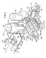
- FIG. 1 is a schematic perspective view of a workpiece feeding apparatus according to an embodiment of the present invention
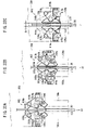
- FIG. 2 is a schematic perspective view of the structure of a branched transporting mechanism
- FIG. 3 is a schematic front elevational view of the structure of the branched transporting mechanism
- FIG. 4 is a schematic plan view of the structure of a rotating mechanism
- FIG. 5 is a schematic perspective view of the structure of a transportation vehicle
- FIG. 6 is a perspective view of the main structure of a wire gripping mechanism
- FIG. 7 is a fragmentary plan view of the structure of the wire gripping mechanism
- FIG. 8 is a fragmentary vertical cross-sectional view of the structure of the wire gripping mechanism
- FIG. 9 is a schematic perspective view of the structure of a lifting/lowering apparatus.
- FIG. 10 is a schematic plan view of a fixing device with fingers closed
- FIG. 11 is a schematic plan view of the fixing device with the fingers open
- FIG. 12 is a schematic plan view of the structure of a workpiece placement plate of the transportation vehicle.
- FIG. 13 is a vertical cross-sectional view taken along line XIII—XIII of FIG. 12 ;
- FIG. 14 is a plan view of the structure of a second plate incorporated in the workpiece placement plate shown in FIG. 12 ;
- FIG. 15 is a plan view of the structure of a third plate incorporated in the workpiece placement plate shown in FIG. 12 ;
- FIG. 16 is a view illustrative of the manner in which the wire gripping mechanism shown in FIGS. 6 through 8 operates to grip a wire;
- FIGS. 17A through 17C are views showing successive stages of a procedure for the wire gripping mechanism to release the wire;
- FIG. 18 is a vertical cross-sectional view illustrative of the manner in which a small workpiece is placed on the workpiece placement plate shown in FIG. 12 ;
- FIG. 19 is a vertical cross-sectional view illustrative of the manner in which a large workpiece is placed on the workpiece placement plate shown in FIG. 12 ;
- FIG. 20 is a plan view showing an interference region created between the small workpiece and the large workpiece
- FIG. 21 is a vertical cross-sectional view illustrative of the manner in which a workpiece is placed after the interference region shown in FIG. 20 is removed;
- FIG. 22 is a schematic perspective view of a workpiece placement plate having another structure
- FIG. 23 is a plan view of the structure of a second plate incorporated in the workpiece placement plate shown in FIG. 22 ;
- FIG. 24A is a schematic plan view of the structure of a second placement plate of the lifting/lowering apparatus and the workpiece placement plate of the transportation vehicle;
- FIG. 24B is a schematic front elevational view of the structure of the second placement plate of the lifting/lowering apparatus and the workpiece placement plate of the transportation vehicle;
- FIGS. 25A and 25B are perspective views illustrative of the manner in which a workpiece is transferred between the lifting/lowering apparatus and the transportation vehicle;
- FIGS. 26A through 26E are views showing successive stages of a procedure for transferring workpieces
- FIGS. 27A through 27D are views showing successive stages of a procedure for the branched transporting mechanism to branch the direction of a transportation vehicle
- FIG. 28 is a perspective view of the main structure of a wire gripping mechanism according to another embodiment of the present invention.
- FIG. 29 is a fragmentary plan view of the structure of the wire gripping mechanism according to the other embodiment of the present invention.
- FIG. 30 is a fragmentary bottom view of the structure of the wire gripping mechanism according to the other embodiment of the present invention.
- FIG. 31 is a schematic front elevational view of the structure of the wire gripping mechanism according to the other embodiment of the present invention.
- FIGS. 32A through 32C are views showing successive stages of a procedure for the wire gripping mechanism according to the other embodiment shown in FIGS. 28 through 31 to release a wire.
- a workpiece feeding apparatus 10 is basically disposed in a production system that is made up of a plurality of working blocks arranged in a crisscross pattern.
- the production system comprises a mechanical production system in which a workpiece that has been processed in one working block is moved by the workpiece feeding apparatus 10 to another working block where the workpiece is processed.
- the production system according to the present embodiment has a working block A and a working block B.
- the working block A and the working block B are basically coupled to each other by rails.
- the working block A and the working block B have respective end transportation mechanisms 12 kept at a predetermined height.
- Each of the end transportation mechanisms 12 has upper and lower pulleys 14 , 16 rotatably supported therein which are slightly displaced from each other.
- Each of the end transportation mechanisms 12 has a set of legs 17 between which the pulleys 14 , 16 are supported.
- a rail 18 is held on the distal ends of the legs 17 .
- the rail 18 is of an inverted U-shaped cross-sectional shape bent from a metal plate and has lower ends 19 a , 19 b extending in respective opposite directions.
- the wheels of transportation vehicles, described later, are rollingly placed on the lower ends 19 a , 19 b.
- a wire 20 extending as a loop along the rail 18 has a loop end trained around the pulleys 14 , 16 .
- the wire 20 has an opposite loop end trained around pulleys 116 , 118 of a branched transporting mechanism 100 to be described later.
- the wire 20 extends from a position above the rail 18 to the pulley 14 , is curved downwardly around the pulley 14 , then extends from the pulley 16 into a space defined between the lower ends 19 a , 19 b of the rail 18 , and extends as an endless loop to the branched transporting mechanism 100 .
- the end transportation mechanisms 12 have a main structure which is basically identical in part to the main structure of the branched transporting mechanism 100 , and will not be described in detail below.
- the branched transporting mechanism 100 will be described below.
- the branched transporting mechanism 100 is held in an elevated position.
- the branched transporting mechanism 100 has a substantially cylindrical body 104 housing therein a motor 106 (second drive source) and a gear train 108 directly coupled to the rotational shaft (not shown) of the motor 106 .
- the motor 106 is associated with an encoder 102 for detecting the rotational angle of the motor 106 .
- a shaft 110 mounted on the distal end of the gear train 108 has a lower end exposed downwardly from the cylindrical body 104 .
- Pulley holding legs 112 are fixed to an outer circumferential wall of the cylindrical body 104 .
- Each of the legs 112 has a pair of flat plates 114 a , 114 b extending obliquely downwardly, with pulleys 116 , 118 being rotatably supported between the flat plates 114 a , 114 b that are spaced a predetermined distance from each other.
- the pulley 116 is positioned slightly upwardly of the pulley 118 , and is coupled to a motor 120 (first drive source) that is held on the cylindrical body 104 through a gear train 122 .
- the rotational drive power of the motor 120 is reduced in speed by the gear train 122 and applied to rotate the pulley 116 .
- the wire 20 is trained around the pulleys 14 , 16 of the end transporting mechanism 12 and the pulleys 116 , 118 of the branched transporting mechanism 100 .
- the branched transporting mechanism 100 has four legs 112 mounted on the outer circumferential wall of the cylindrical body 104 and angularly spaced at 90° from adjacent ones of the legs 112 .
- the motor 120 and the gear train 122 are fixed to at least two legs 112 that are disposed in symmetrical positions. Those legs 112 which are free of the motor 120 and the gear train 122 are associated with wires 20 that are trained around the pulleys 14 , 16 of companion end transporting mechanisms 12 which are equipped with motors 120 and gear trains 122 . Therefore, each wire 20 is actuated by the motor 120 and the gear train 122 of either one of the branched transporting mechanism 100 and the end transporting mechanism 12 that are associated with that wire 20 .
- guide plates 124 a , 124 b that are spaced a predetermined distance from each other are fixed to the respective lower ends of the flat plates 114 a , 114 b of each of the legs 112 .
- the guide plates 124 a , 124 b are kept at substantially the same height as the lower ends 19 a , 19 b of the rail 18 .
- Wire grip release plates 128 a , 128 b comprising flat plates which have tapered distal ends 126 a , 126 b (see FIGS. 17A through 17C ) are secured to the respective lower ends of the guide plates 124 a , 124 b.
- a support plate 132 extending from the cylindrical body 104 may be attached to one of the legs 112 , and, as shown in FIG. 2 , a tension pulley 134 (tension adjusting means) may be rotatably supported so as to be vertically movable on a position adjustment plate 133 mounted on the distal end of the support plate 132 .
- the tension pulley 134 serves to apply a predetermined tension to the wire 20 that is trained around the pulleys 14 , 16 , 116 , 118 .
- a rotating mechanism 200 which is rotatable in unison with the shaft 110 is disposed below the shaft 110 .
- the rotating mechanism 200 has a horizontal plate 202 fixed to the end of the shaft 110 and holding brackets 204 a , 204 b , 204 c disposed at spaced intervals and fixed to the horizontal plate 202 .
- the holding brackets 204 a , 204 b , 204 c have lower ends interconnected by a plate 206 mounted thereon and other lower ends interconnected by a plate 208 mounted thereon.
- a large-diameter driven roller 210 is mounted on the plate 206 by a holder 209 , and a motor 212 (third drive source) is also mounted on the plate 206 by a holder 211 .
- the rotational drive power of the motor 212 is reduced in speed by a gear train 214 and applied to rotate a drive roller 216 .
- the drive roller 216 and the driven roller 217 have substantially the same diameter, and are operatively connected to each other by a belt 217 .
- FIG. 4 shows in plan the structure of the rotating mechanism 200 .
- Support shafts 226 , 228 are supported on the plate 208 , and L-shaped holding arms 230 , 232 are angularly movably mounted on the respective support shafts 226 , 228 .
- Driven rollers 222 , 224 are rotatably held on respective ends of the holding arms 230 , 232 .
- Shafts 234 , 236 are mounted on respective other ends of the holding arms 230 , 232 .
- Coil springs 242 , 244 are disposed around the respective shafts 234 , 236 and interposed between the other ends of the holding arms 230 , 232 and support bars 238 , 240 mounted on the plate 208 .
- the driven rollers 222 , 224 are biased under the resiliency of the coil springs 242 , 244 to move toward the drive roller 216 as indicated by the two-dot-and-dash lines in FIG. 4 .
- a plate 250 is disposed below the horizontal plate 202 , i.e., within the holding brackets 204 a , 204 b , 204 c , and a plate 252 is fixed to the plate 250 perpendicularly thereto.
- a turn plate 254 is fixed to a lower portion of the plate 252 .
- the turn plate 254 has steps providing guide regions 255 a , 255 b on elongate opposite sides thereof for rollers of a transportation vehicle 300 , described later, to roll thereon.
- the guide regions 255 a , 255 b have substantially the same width and height as the lower ends 19 a , 19 b of the rail 18 and the guide plates 124 a , 124 b.
- the transportation vehicle 300 which feeds a workpiece for the branched transporting mechanism 100 to transport the workpiece in a different direction will be described below with reference to FIG. 5 .
- the transportation vehicle 300 includes a support base 302 having tapered surfaces 304 a , 304 b on one end thereof and tapered surfaces 306 a , 306 b on the other end thereof (see FIG. 7 ).
- a pair of holder plates 308 a , 308 b are erected on the support base 302 , and rollers 312 a , 312 b and rollers 314 a , 314 b are rotatably supported on the respective holder plates 308 a , 308 b.
- Substantially rectangular guides 316 a , 316 b , 318 a , 318 b made of synthetic resin are fixed to the holder plates 308 a , 308 b at positions inwardly of the rollers 312 a , 312 b , 314 a , 314 b .
- a plate 320 extends downwardly from the lower surface of the support base 302 , and substantially U-shaped rods 324 a , 324 b are fixed to respective opposite ends of a plate 322 that is mounted on the lower end of the plate 320 .
- the rods 324 a , 324 b hold workpiece placement plates 326 a , 326 b , respectively.
- the workpiece placement plates 326 a , 326 b comprise comb-toothed flat plates spaced from each other by a distance L.
- Each of the workpiece placement plates 326 a , 326 b has teeth that are spaced from adjacent ones by a distance L 3 . Structural details of the workpiece placement plates 326 a , 326 b will be described later.
- a wire gripping mechanism 350 incorporated in the transportation vehicle 300 will be described below.
- the wire gripping mechanism 350 serves to transport the transportation vehicle 300 with the wire 20 , and cooperate with the branched transporting mechanism 100 in changing the direction in which the transportation vehicle 300 is transported.
- FIGS. 6 through 8 show the structure of the wire gripping mechanism 350 .
- the wire gripping mechanism 350 is mounted on the upper surface of the support base 302 .
- a line X represents a central line of the wire gripping mechanism 350 and also a center of movement of the wire 20 to be gripped.
- the wire 20 can be rotated in opposite directions on the line X.
- the wire gripping mechanism 350 comprises a first grip unit 352 , a second grip unit 354 , a third grip unit 356 , and a fourth grip unit 358 which are disposed at respective positions a, b, c, d on the upper surface of the support base 302 , as shown in FIG. 7 .
- Each of the first through fourth grip units 352 , 354 , 356 , 358 has cams 360 , 362 each having an arcuate surface.
- the cams 360 , 362 are disposed axially symmetrically on both sides of the line X.
- the cams 360 , 362 are disposed differently in the first through fourth grip units 352 , 354 , 356 , 358 .
- the cam 360 is disposed on the left side of the line X and the cam 362 is disposed on the right side of the line X in FIG. 7 .
- the cam 362 is disposed on the left side of the line X and the cam 360 is disposed on the right side of the line X, in angular positions turned 180° from those in the first grip unit 352 , in FIG. 7 .
- the first through fourth grip units 352 , 354 , 356 , 358 have a common mechanism for gripping the wire 20 though their cams 360 , 362 are mounted in different directions.
- the cam 360 is disposed on the left side of the line X with a wire gripping surface 398 directed toward the line X.
- the cam 360 is rotatably supported on a rotational shaft 370 that is mounted on the support base 302 of the transportation vehicle 300 .
- a spring 382 is disposed around the rotational shaft 370 and has an end seated on a holder plate 308 a that is erected on the support base 302 and an opposite end seated in a chamber 374 that is defined in the cam 360 .
- a gear 386 is pivotally supported on the lower surface of the cam 360 with a toothed surface directed toward the line X, and a cover 390 is fixed to the upper surface of the cam 360 .
- a cylindrical cam releaser 378 projecting upwardly is fixedly mounted on the cam 360 .
- the cover 390 , the cam 360 , and the gear 386 are of a three-layer structure as shown in FIG. 8 .
- the cam 362 is disposed on the right side of the line X with a wire gripping surface 399 directed toward the line X.
- the cam 362 is rotatably supported on a rotational shaft 372 that is mounted on the support base 302 .
- a spring 382 is disposed around the rotational shaft 372 and has an end seated on a holder plate 308 b that is erected on the support base 302 and an opposite end seated in a chamber 376 that is defined in the cam 362 .
- a gear 388 is fixed to the lower surface of the cam 362 with a toothed surface directed toward the line X, and a cover 392 is fixed to the upper surface of the cam 362 .
- a cylindrical cam releaser 380 projecting upwardly is fixedly mounted on the cam 362 .
- the cover 392 , the cam 362 , and the gear 388 are of a three-layer structure (see FIG. 8 ).
- the numbers of teeth of the gears 386 , 388 are equal to each other, and the gears 386 , 388 operate as synchronizing gears for preventing the cams 360 , 262 from differing in angular displacements.
- the covers 390 , 392 are of such a structure that they overlap each other when the cams 360 , 362 grip the wire 30 , and hence have a function to prevent the wire 20 from being released.
- the second grip unit 354 and the fourth grip unit 358 are in an unclamping state
- the first grip unit 352 and the third grip unit 356 are in an unclamping state
- the second grip unit 354 and the fourth grip unit 358 are in a clamping state.
- a lifting/lowering apparatus 400 for bringing a workpiece transported by the transportation vehicle 300 thus constructed into a processing apparatus will be described below.
- the lifting/lowering apparatus 400 is generally disposed between the end transporting mechanism 12 and the branched transporting mechanism 100 , and positioned in the vicinity of the rail 18 (see FIG. 1 ).
- the lifting/lowering apparatus 400 includes a base 402 and a plurality of frames 404 a through 404 d extending upwardly from the base 402 .
- the frames 404 c , 404 d have a height reaching a position near the wire 20 .
- Beams 406 a through 406 h are transversely mounted on the frames 404 a through 404 d .
- a motor 408 is disposed in the frames 404 a through 404 d of the base 402 , and has a rotatable drive shaft (not sown) connected by a gear train 410 to a pulley 412 .
- the lifting/lowering apparatus 400 has a lower shaft 414 and an upper shaft 416 which extend transversely between the frames 404 c , 404 d and have opposite ends rotatably supported by respective pairs of bearings 418 , 420 .
- Sprockets 422 , 424 are fixed to the lower shaft 414 and the upper shaft 416 near their opposite ends.
- Chains 426 are trained around the upper and lower sprockets 422 , 424 .
- a pulley 428 is fixedly mounted on the lower shaft 414 , and a belt 430 is trained around the pulley 412 and the pulley 428 .
- a placement table 450 (workpiece placement table) is fixed to the chains 426 by fixtures 429 .
- the placement table 450 includes a plurality of rollers 452 , 454 projecting therefrom which roll on the frames 404 c , 404 d that are of a U-shaped cross-section for traveling in the vertical direction in FIG. 9 .
- the placement table 450 includes a rectangular framework 456 on which there are disposed a first placement surface 458 (first workpiece placement surface) and a second placement surface 460 (second workpiece placement surface) that are vertically spaced from each other by a predetermined distance.
- the first placement surface 458 has first and second comb-toothed placement members 462 a , 462 b
- the second placement surface 460 also has first and second comb-toothed placement members 464 a , 464 b.
- the first and second placement members 462 a , 462 b of the first placement surface 458 are spaced from each other by a predetermined distance.
- the second placement surface 460 comprises a first plate 466 a and a second plate 466 b .
- the first and second placement members 464 a , 464 b of the second placement surface 460 are fixed respectively to the first plate 466 a and the second plate 466 b .
- the first plate 466 a and the second plate 466 b are spaced from each other by a predetermined distance, and have confronting end faces whose corners are tapered so as to provide spreading edges.
- a fixing device 500 for temporarily positioning and fixing the transportation vehicle 300 is mounted on an upper portion of the lifting/lowering apparatus 400 (see FIGS. 10 and 11 ).
- the fixing device 500 comprises a housing 504 accommodating therein a drive source 502 comprising a rotary actuator, rods 506 a , 506 b projecting outwardly from the drive source 502 , an arm 508 secured to the housing 504 , and bent fingers 510 a , 510 b swingably supported on the arm 508 .
- the fingers 510 a , 510 b have respective ends pivotally supported respectively on the rods 506 a , 506 b .
- the reference characters 512 a , 512 b represent position detecting sensors.
- the workpiece placement plates 326 a , 326 b of the transportation vehicle 300 comprise respective first plates 328 a , 328 b (drop prevention plates), second plates 330 a , 330 b (positioning plates), and third plates 332 a , 332 b (positioning plates), that are successively stacked upwardly in the order named.
- the first plates 328 a , 328 b comprise comb-toothed flat plates.
- the first plates 328 a , 328 b have teeth 614 each having a width L 2 and a length L 5 and recesses 616 each having a width L 3 , the teeth 614 and the recesses 616 alternating with each other.
- the second plates 330 a , 330 b have teeth which are similar to the teeth 614 of the first plates 328 a , 328 b , but cut out along the profile of a workpiece W 1 to provide a space area complementary to the workpiece W 1 .
- FIG. 12 the first plates 328 a , 328 b have teeth 614 each having a width L 2 and a length L 5 and recesses 616 each having a width L 3 , the teeth 614 and the recesses 616 alternating with each other.
- the second plates 330 a , 330 b have teeth which are similar to the teeth 614 of the first plates
- the third plates 332 a , 332 b have teeth which are similar to the teeth 614 of the first plates 328 a , 328 b , but cut out along the profile of a workpiece W 2 to provide a space area complementary to the workpiece W 2 .
- the second plates 330 a , 330 b provide a space area A 1 complementary to the workpiece W 1
- the third plates 332 a , 332 b provide a space area A 2 complementary to the workpiece W 2 .
- the workpiece W 1 and the workpiece W 2 have different shapes, respectively, and the workpiece W 1 is smaller in size than the workpiece W 2 .
- the profile of the workpiece W 1 is different in shape from the profile of the workpiece W 2 .
- the space area A 1 complementary to the profile of the workpiece W 1 is fully included in the space area A 2 complementary to the profile of the workpiece W 2 .
- the end transporting mechanisms 12 and the branched transporting mechanisms 100 in the working blocks A, B are electrically connected to auxiliary controllers 750 , which are electrically connected to a main controller 700 .
- the reference character 800 represents a workpiece processing station.
- the workpiece feeding apparatus 10 is basically constructed as described above. Operation and advantages of the workpiece feeding apparatus 10 will be described below.
- FIG. 16 shows the first grip unit 352 for gripping the wire 20 . Since the first through fourth grip units 352 , 354 , 356 , 358 have a common mechanism and operate in the same manner for gripping the wire 20 though they are mounted in different directions, the first grip unit 352 will be described below. For the sake of clarity, the gears 386 388 and the covers 390 , 392 are omitted from illustration in FIG. 16 .
- the wire gripping surface 398 of the cam 360 have opposite ends that are spaced different distances from the rotational shaft 370 . Specifically, if the distance from the rotational shaft 370 to one end of the wire gripping surface 398 is represented by R 1 and the distance from the rotational shaft 370 to the other end of the wire gripping surface 398 is represented by R 2 , then the distances R 1 , R 2 are related to each other as R 1 ⁇ R 2 .
- the cam 362 is of a structure identical to the cam 360 .
- the wire gripping surface 298 of the cam 360 is differently spaced from the rotational shaft 370 at its opposite ends and the wire gripping surface 299 of the cam 362 is also differently spaced from the rotational shaft 372 at its opposite ends.
- the first grip unit 352 grips the wire 20 when the wire 20 rotates in a normal direction (the direction indicated by the arrow X 1 ) and does not grip the wire 20 when the wire 20 rotates in the reverse direction (the direction indicated by the arrow X 2 ).
- the springs 382 urge the cams 360 , 362 to turn in the respective directions indicated by the arrows X 3 for holding the wire gripping surfaces 398 , 399 of the cams 360 , 362 in contact with the wire 20 at all times. Consequently, the wire gripping mechanism 350 is self-locked by the rotational drive force of the wire 20 depending on the direction in which the wire 20 rotates (normal direction or reverse direction).
- the wire gripping mechanism 350 grips the wire 20 based on the above operation. Furthermore, as shown in FIG. 7 , the wire gripping mechanism 350 has the first grip unit 352 disposed in the position a and the second grip unit 354 , whose angular position is turned 180° from the first grip unit 352 about the line X, disposed in the position b. With this arrangement, when the wire 20 moves in the direction indicated by the arrow X 1 (rotates in the normal direction), the second grip unit 354 grips the wire 20 , and the first grip unit 352 does not grip the wire 20 .
- the wire 20 can be gripped irrespective of the direction in which the wire 20 rotates.
- the wire 20 rotates in only the normal direction or the reverse direction, then either one of the first grip unit 352 and the second grip unit 354 may be employed.
- the wire gripping mechanism 350 also has the third grip unit 356 , which is oriented in the same direction as the first gripping unit 352 , disposed in the position c and the fourth grip unit 358 , which is oriented in the same direction as the second gripping unit 354 , disposed in the position d.
- the third grip unit 356 which is oriented in the same direction as the first gripping unit 352 , disposed in the position c
- the fourth grip unit 358 which is oriented in the same direction as the second gripping unit 354 , disposed in the position d.
- FIGS. 17A through 17C are views showing successive stages of a procedure in which the wire grip release plates 128 a , 128 b release the wire 20 from the wire gripping mechanism 350 .
- the transportation vehicle 300 is released from the rotational drive action of the wire 20 when its direction is branched by the branched transporting mechanism 100 , and stops its motion at the spot where it is released from the wire 20 . Therefore, the branched transporting mechanism 100 has the wire grip release plates 128 a , 128 b for releasing the wire 20 from the wire gripping mechanism 350 .
- first through fourth grip units 352 , 354 , 356 , 358 have a common mechanism and operate in the same manner for gripping the wire 20 though they are mounted in different directions, the first grip unit 352 will be described below by way of example.
- the transportation vehicle 300 moves in the direction indicated by the arrow X 1 while the first gripping unit 352 is gripping the wire 20 (the state shown in FIG. 17A ). At this time, however, the cam releaser 378 of the cam 360 and the cam releaser 380 of the cam 362 are not yet in contact with the wire grip release plates 128 a , 128 b.
- the cam releasers 378 , 380 are brought into contact with the wire grip release plates 128 a , 128 b (the state shown in FIG. 17B ). At this time, the cam releasers 378 , 380 relatively slide on the slanted surfaces of the distal ends of the wire grip release plates 128 a , 128 b . Simultaneously, the cam 360 fixed to the cam releaser 378 rotates in the direction indicated by the arrow X 4 about the rotatable shaft 370 , and the cam 362 fixed to the cam releaser 380 rotates in the direction indicated by the arrow X 4 about the rotatable shaft 372 (see FIG. 16 ). That is, as the transportation vehicle 300 moves in the direction indicated by the arrow X 1 , the cams 360 , 362 are spaced away from each other, releasing the wire 20 .
- the cam releasers 378 , 380 Upon continued movement of the transportation vehicle 300 in the direction indicated by the arrow X 1 , the cam releasers 378 , 380 relatively move past the tapered ends 126 a , 126 b of the wire grip release plates 128 a , 128 b , and thereafter arrive at the main bodies of the wire grip release plates 128 a , 128 b (the state shown in FIG. 17C ).
- the gap between the cams 360 , 362 is increased to the maximum value (corresponding to L 10 ), and remains constant as long as the cam releasers 378 , 380 are kept in contact with the wire grip release plates 128 a , 128 b .
- the maximum gap L 10 is wider than the width L 11 of the pulley 118 , and hence does not obstruct the passage of the pulley 118 therethrough.
- the workpiece feeding apparatus for placing the small workpiece W 1 on the workpiece placement plates 326 a , 326 b will be described below.
- the workpiece W 1 passes vertically through the third plates 332 a , 332 b and the second plates 330 a , 330 b without suffering interference therewith.
- the workpiece W 1 does not drop off as it is placed on the lowest first plates 328 a , 328 b .
- the second plates 330 a , 330 b are cut out along the profile of the workpiece W 1 , they effectively hold the workpiece W 1 to prevent the workpiece W 1 from being positionally displaced.
- the workpiece feeding apparatus for placing the large workpiece W 2 on the workpiece placement plates 326 a , 326 b will be described below.
- the workpiece W 2 passes vertically through the third plates 332 a , 332 b without suffering interference therewith.
- the workpiece W 2 is placed on the second plates 330 a , 330 b , and does not drop off. Because the third plates 332 a , 332 b are cut out along the profile of the workpiece W 2 , they effectively hold the workpiece W 2 to prevent the workpiece W 2 from being positionally displaced.
- the workpiece W 1 can easily pass vertically through the third plates 332 a , 332 b without suffering interference therewith, by removing a region S 2 corresponding to the interference region S 1 from the teeth 614 of the third plates 332 a , 332 b to provide a corresponding a space area (third space area), as shown in FIG. 21 .
- the workpiece W 1 is placed on the first plates 328 a , 328 b and positioned by the second plates 330 a , 330 b .
- the region S 2 corresponding to the interference region S 1 in the third plates 332 a , 332 b is also of a small area. Therefore, the effect that the third plates 332 a , 332 b have on the positioning of the workpiece W 2 is negligibly small.
- the workpiece placement plates 326 a , 326 b are designed to handle two differently shaped types of workpieces (W 1 , W 2 ).
- the workpiece placement plates 326 a , 326 b are not limited to those two workpieces, but may be designed to handle three or more types of workpieces by increasing the number of plates used.
- the workpiece placement plates 326 a , 326 b may comprise workpiece placement plates 326 c , 326 d , as shown in FIG. 22 .
- the workpiece placement plates 326 c , 326 d comprise respective first plates 328 c , 328 d (drop prevention plates) and respective second plates 330 c , 330 d (positioning plates) positioned respectively on the first plates 328 c , 328 d.
- the first plates 328 c , 328 d are identical in structure to the first plates 328 a , 328 b of the workpiece placement plates 326 a , 326 b , and serve the purpose of preventing workpieces from dropping off.
- the second plates 330 c , 330 d have their teeth 614 cut out along the profile of a workpiece W 3 placed in a posture P 1 and also along the profile of the workpiece W 3 placed in a posture P 2 that is 180° angularly displaced from the posture P 1 , providing a corresponding space area.
- the workpiece W 3 when the workpiece W 3 is placed in either the posture P 1 or the posture P 2 on the workpiece placement plates 326 a , 326 b , the workpiece W 3 can pass vertically through the second plates 330 c , 330 d without suffering interference therewith.
- the workpiece W 3 is positioned by the second plates 330 c , 330 d , and prevented from dropping off by the first plates 328 c , 328 d.
- the posture P 2 is 180° angularly displaced from the posture P 1 .
- the posture P 2 is not limited to the posture that is 180° angularly displaced from the posture P 1 , but may be any posture with respect to the posture P 1 , and the space area provided by the workpiece placement plates 326 c , 326 d may be changed in shape accordingly.
- the workpiece placement plates 326 a , 326 b and the workpiece placement plates 326 c , 326 d may be combined with each other. With this arrangement, a plurality of workpieces having different shapes can be transported reliably in respective desired positions or postures.
- the above structural details of the workpiece placement plates 326 a , 326 b and/or the workpiece placement plates 326 c , 326 d may be applied to the placement surfaces 458 , 460 of the lifting/lowering apparatus 400 . Such modifications allow workpieces to be processed easily and reliably in the workpiece processing station 800 .
- FIG. 24A is a plan view of the structure of the second placement surface 460 and the workpiece placement plates 326 a , 326 b as they are placed in a horizontal plane
- FIG. 24B is a front elevational view thereof. Since the first placement surface 458 and the second placement surface 460 are identical in shape to each other, the second placement surface 460 will be described below.
- the arrows represent the directions in which the transportation vehicle 300 moves, and the reference character 600 represents a gap, or a passage, between the first and second placement members 464 a , 464 b .
- the plate 320 of the transportation vehicle 300 passes through the gap (the passage 600 ).
- the passage 600 has a width L 1 greater than the width of the plate 320 .
- the first and second placement members 464 a , 464 b have teeth 610 each having a width L 2 and recesses 612 each having a width L 3 , the teeth 610 and the recesses 612 being aligned with each other.
- the workpiece placement plates 326 a , 326 b also have teeth 614 each having a width L 2 and recesses 616 each having a width L 3 , the teeth 614 and the recesses 616 being aligned with each other.
- the widths L 2 , L 3 are related to each other as L 3 >L 2 .
- the teeth 610 of the first and second placement members 464 a , 464 b have a longitudinal length L 4
- the recesses 616 in the workpiece placement plates 326 a , 326 b have a longitudinal length L 5 , the lengths L 4 , L 5 being related to each other as L 5 >L 4 .
- the teeth 614 of the workpiece placement plates 326 a , 326 b , the teeth 610 of the first and second placement members 464 a , 464 b , and the recesses 616 in the workpiece placement plates 326 a , 326 b are positioned in superposed relation, because the relationships L 3 >L 2 and L 5 >L 4 , one set of teeth (e.g., the teeth 610 of the first placement member 464 a can pass through another set of recesses (e.g., the recesses 616 in the workpiece placement plates 326 a , 326 b ).
- the first plate 466 a and the first placement member 464 a , and the second plate 466 b and the second placement member 464 b are spaced from each other by a distance (L 7 ), providing a space 618 therebetween.
- the space 618 has a gap L 7 that is greater than the thickness L 6 of the workpiece placement plates 326 a , 326 b .
- a workpiece is transferred based on the fact that the second placement surface 460 and the workpiece placement plates 326 a , 326 b pass through each other without causing interference.
- FIGS. 25A and 25B A specific example of a process for transferring a workpiece placed on the workpiece placement plates 326 a , 326 b to the second placement surface 460 will be described below with reference to FIGS. 25A and 25B . Since the second placement surface 460 and the first placement surface 458 are structurally identical to each other, the second placement surface 460 will be described below by way of example.
- FIG. 25A shows a state in which the workpiece placement plates 326 a , 326 b holds a workpiece and reaches a position above the second placement surface 460 . It is assumed that at this time the workpiece placement plates 326 a , 326 b are fixed by the fixing device 500 , and as shown in FIGS. 24A and 24B , the teeth 610 of the second placement surface 460 and the recesses 616 in the workpiece placement plates 326 a , 326 b , and the recesses 612 in the second placement surface 460 and the teeth 614 of the workpiece placement plates 326 a , 326 b are positioned in superposed relation. At this time, the workpiece placement plates 326 a , 326 b have not yet entered the space 618 .
- a process for transferring a workpiece from the second placement surface 460 to the workpiece placement plates 326 a , 326 b will be described below.
- the lifting/lowering apparatus 400 elevates the second placement surface 460 with a workpiece placed thereon to a position slightly above the workpiece placement plates 326 a , 326 b , and keeps the second placement surface 460 in that position.
- the transportation vehicle 300 then reaches the position. At this time, since the second placement surface 460 waits in the position slightly above the workpiece placement plates 326 a , 326 b , the workpiece placement plates 326 a , 326 b enter the space 618 .
- the second placement surface 460 is slightly lowered, whereupon the teeth 614 pass through the recesses 612 and the workpiece placement plates 326 a , 326 b move out of the space 618 , receiving the workpiece from the second placement surface 460 (see FIGS. 24A and 24B ).
- a procedure for transferring a workpiece from the transportation vehicle 300 to a working block (and a procedure for transferring a workpiece from a working block to the transportation vehicle 300 ) will be described below with reference to FIGS. 26A through 26E .
- a fixed point Z 1 represents the height of the workpiece placement plates 326 a , 326 b of the transportation vehicle 300 . Since the transportation vehicle 300 itself does not move vertically, the fixed point Z 1 , i.e., the height of the workpiece placement plates 326 a , 326 b , is constant.
- the fixed point Z 1 serves as a transfer position for transferring a workpiece from the transportation vehicle 300 to the placement table 450 of the lifting/lowering apparatus 400 (or a transfer position for transferring a workpiece from the placement table 450 to the transportation vehicle 300 ).
- a fixed point Z 2 represents the height of a working surface of the working block.
- the fixed point Z 2 Since the working block itself does not move vertically, the fixed point Z 2 , i.e., the height of the working surface, is constant.
- the fixed point Z 2 serves as a transfer position for transferring a workpiece from the placement table 450 to the working block (or a transfer position for transferring a workpiece from the working block to the placement table 450 ).
- a workpiece is received from the fixed position Z 1 or the fixed position Z 2 and transferred thereto when the lifting/lowering apparatus 400 lifts and lowers the placement table 450 .
- the reference character 650 represents a workpiece which has not yet been processed by the working block (hereinafter referred to as “unprocessed workpiece”)
- the reference character 652 represents a workpiece which has been processed by the working block (hereinafter referred to as “processed workpiece”).
- the working block receives the unprocessed workpiece 650 from a preceding process, processes the unprocessed workpiece 650 into the processed workpiece 652 , and transfers the processed workpiece 652 to a next process (not shown).
- the lifting/lowering apparatus 400 For receiving the unprocessed workpiece 650 carried from the preceding process, the lifting/lowering apparatus 400 lifts the placement table 450 and stops the placement table 450 when the first placement surface 458 reaches a position slightly below the fixed point Z 1 . Then, the transportation vehicle 300 with the unprocessed workpiece 650 placed thereon moves from the preceding process to the transfer position of the lifting/lowering apparatus 400 in the working block, and is temporarily positioned and fixed by the fixing device 500 .
- the processed workpiece 652 waits in the working block (the state shown in FIG. 26A ).
- the teeth 614 pass through the recesses 612 , the workpiece placement plates 326 a , 326 b enter the space 618 in the first placement surface 458 , the first placement surface 458 ascends above the workpiece placement plates 326 a , 326 b , and the unprocessed workpiece 650 placed on the workpiece placement plates 326 a , 326 b is released from the workpiece placement plates 326 a , 326 b and transferred to the first placement surface 458 .
- the transportation vehicle 300 which has become empty by transferring the unprocessed workpiece 650 to the first placement surface 458 moves to another working block.
- the lifting/lowering apparatus 400 lowers the placement table 450 with the unprocessed workpiece 650 placed on the first placement surface 458 , and stops the placement table 450 when the second placement surface 460 reaches the fixed point Z 2 (the state shown in FIG. 26B ).
- the lifting/lowering apparatus 400 lifts the placement table 450 , and stops the placement table 450 when the first placement surface 458 reaches the fixed point Z 2 (not shown).
- the unprocessed workpiece 650 placed on the first placement surface 458 is transferred to the working block.
- the lifting/lowering apparatus 400 lifts the placement table 450 with the processed workpiece 652 placed on the second placement surface 460 , and stops the placement table 450 when the second placement surface 460 reaches a position slightly higher than the fixed point Z 1 .
- the transportation vehicle 300 with the workpiece placement plates 326 a , 326 b which are empty moves from another working block.
- the transportation vehicle 300 reaches the transfer position of the lifting/lowering apparatus 400 in the working block (the state shown in FIG. 26D ), and is temporarily positioned and fixed by the fixing device 500 .
- the workpiece placement plates 326 a , 326 b enter the space 618 .
- the teeth 614 pass through the recesses 612 and the workpiece placement plates 326 a , 326 b move out of the space 618 , releasing the processed workpiece 652 placed on the second placement surface 460 from the second placement surface 460 and transferring the processed workpiece 652 to the workpiece placement plates 326 a , 326 b.
- the transportation vehicle 300 moves from that position to the next process for supplying the processed workpiece 652 received from the second placement surface 460 to the next process.
- the lifting/lowering apparatus 400 lifts the placement table 450 and stops the placement table 450 when the first placement surface 458 reaches a position slightly below the fixed point Z 1 (the state shown in FIG. 26E ).
- the unprocessed workpiece 650 is shown as being transferred to the first placement surface 458 of the placement table 450
- the processed workpiece 652 is shown as being transferred to the second placement surface 460 of the placement table 450
- the process of transferring a workpiece according to the present embodiment is not limited to such a combination.
- the transportation vehicle 300 can transfer the unprocessed workpiece 650 to the second placement surface 460 .
- the transportation vehicle 300 can receive the processed workpiece 652 placed on the first placement surface 458 , and transfer the processed workpiece 652 to another working block. In this manner, the freedom of the transferring process is further increased.
- the wire grip release plates 128 a , 128 b fixed to the reverse surfaces of the guide plates 124 a , 124 b cause the wire gripping mechanism 350 fixedly mounted on the transportation vehicle 300 to release the wire 20 .
- the cam releasers 378 , 380 of the first grip unit 352 are turned by abutment against the wire grip release plates 128 a , 128 b , releasing the first grip unit 352 from the wire 20 as a source wire.
- the second grip unit 354 and the fourth grip unit 358 are in the unclamping state.
- the third grip unit 356 is in the clamping state in which it clamps the wire 20 as the source wire, the transportation vehicle 300 is transported to the turn plate 254 of the branched transporting mechanism 100 .
- the rotating mechanism 200 energizes the motor 212 to rotate at the time a position detecting sensor (not shown) detects that the head of the transportation vehicle 300 reaches the driven roller 210 or the drive roller 216 .
- a position detecting sensor not shown
- the gear train 214 rotates the drive roller 216 and the driven roller 210 , transferring the transportation vehicle 300 onto the turn plate 254 .
- the cam releasers 378 , 380 of the third grip unit 356 of the transportation vehicle 300 reach the wire grip release plates 128 a , 128 b , and the wire grip release plates 128 a , 128 b turn the cam releasers 378 , 380 to release the wire 20 .
- the transportation vehicle 300 is now completely released from the driving action of the wire 20 as the source wire.
- the driven rollers 222 , 224 urge the transportation vehicle 300 toward the drive roller 216 under the resiliency of the coil springs 242 , 244 , preventing the transportation vehicle 300 from being dislodged.
- the transportation vehicle 300 Upon further rotation of the motor 212 , the transportation vehicle 300 is released from the rail 18 as a source rail, and transferred onto the turn plate 254 .
- the completion of the transfer of the transportation vehicle 300 onto the turn plate 254 is detected by a position detecting sensor (not shown).
- the motor 212 When the transfer is completed, the motor 212 is de-energized (the state shown in FIG. 4 ).
- the rotating mechanism 200 is rotated 360° about the shaft 110 by the rotation of the motor 106 .
- a process of feeding the transportation vehicle 300 on the turn plate 254 to the rail 18 as a destination rail will be described below.
- the motor 212 is energized to push the transportation vehicle 300 toward the rail 18 as the destination rail.
- the rollers 312 a , 312 b , 314 a , 314 b of the transportation vehicle 300 roll onto the rail 18 as the destination rail, and the wire gripping mechanism 350 of the transportation vehicle 300 grips the wire 20 as the destination wire.
- the cam releasers 378 , 380 of the first grip unit 352 of the transportation vehicle 300 are spread by the wire grip release plates 128 a , 128 b , the cam releasers 378 , 380 return to their original position, gripping the wire 20 as the destination wire.
- the transportation vehicle 300 is pulled by the driving action of the wire 20 as the destination wire, and pushed by the rotation of the drive roller 216 and the driven roller 210 .
- the third grip unit 356 thereof is spread by the wire grip release plates 128 a , 128 b , and then returns to its original position, gripping the wire 20 as the destination wire.
- the transportation vehicle 300 is driven by the wire 20 as the destination wire, and is released from the turn plate 254 .
- the branching process carried out by the branched transporting mechanism 100 is now ended.
- FIGS. 27A through 27D are views showing successive stages of a procedure for the branched transporting mechanism to branch the direction of the transportation vehicle 300 .
- a source rail a rail on which the transportation vehicle 300 is presently traveling
- destination rails rails on which the transportation vehicle 300 is about to travel next
- the destination rail F is a rail that extends perpendicularly to the right as viewed from the source rail E.
- the destination rail G is a rail that extends perpendicularly to the left as viewed from the source rail E.
- the destination rail H is a rail that is aligned straight with the direction in which the transportation vehicle 300 travels, as viewed from the source rail E.
- the transportation vehicle 300 travels on the source rail E toward the turn plate 254 (the state shown in FIG. 27A ). Then, the transportation vehicle 300 is pulled onto the turn plate 254 (the state shown in FIG. 27B ). The transportation vehicle 300 is pulled by the process described above (see FIG. 4 ). Then, the turn plate 254 onto which the transportation vehicle 300 has been transferred is turned to the right (the state shown in FIG. 27C ). When the turn plate 254 is aligned straight with the destination rail F, the turn plate 254 stops its turning movement. Then, the transportation vehicle 300 on the turn plate 254 is delivered onto the destination rail F. The transportation vehicle 300 is delivered by the process described above (see FIG. 4 ). In this manner, the transportation vehicle 300 is driven on the destination rail F, and is released from the turn plate 254 (the state shown in FIG. 27D ).
- FIGS. 28 through 31 show a wire gripping mechanism 900 according to another embodiment of the present invention.
- the wire gripping mechanism 900 comprises a first grip unit 902 , a second grip unit 904 , a third grip unit 906 , and a fourth grip unit 908 which are disposed at respective positions a, b, c, d on the upper surface of the support base 302 of the transportation vehicle 300 .
- a line X represents a central line of the wire gripping mechanism 900 and also a center of movement of the wire 20 to be gripped.
- the wire 20 can be moved in opposite directions on the line X (the directions indicated by the arrows X 1 , X 2 ).
- first through fourth grip units 902 , 904 , 906 , 908 have a common mechanism for gripping or releasing the wire 20 though they have slightly different structures or are mounted in slightly different directions, the first grip unit 902 will be described below.
- the first grip unit 902 has identical parts disposed laterally symmetrically.
- the parts on one side are represented by reference characters with a suffix “a”, and the parts on the other side are represented by reference characters with a suffix “b”.
- Those parts whose reference characters have no suffix are common parts on both sides.
- the parts on one side of the first grip unit 902 will be described below, and the parts on the other side of the first grip unit 902 will not be described below.
- the first grip unit 902 has a support member 912 a mounted on an end of the position a on the support base 302 .
- the support member 912 a has a shaft hole 914 a defined therein, and the support base 302 has a through hole (not shown) defined therein at the position aligned with the shaft hole 914 a , the through hole having the same diameter as the shaft hole 914 a .
- a shaft 916 a is rotatably inserted in the shaft hole 914 a and the through hole.
- a rotational member 918 a which is triangular as viewed in plan is fixed to the shaft 916 a over the surface of the support base 302 , and a sectorial gear 920 a is fixed to the shaft 916 a beneath the reverse surface of the support base 302 .
- a shaft 922 a is fixed to the rotational member 918 a in a predetermined region thereof, and a grip member 910 a is rotatably supported on the shaft 922 a .
- the grip member 910 a has a grip surface 911 a for gripping the wire 20 over a predetermined range.
- a cylindrical grip releaser 919 a (wire grip release means) projecting upwardly is fixedly mounted on the surface of the rotational member 918 a in a predetermined region thereof.
- the grip member 910 a and the support member 912 a are coupled to each other by a link 924 .
- the link 924 has an end engaging the support member 912 a and another end engaging the grip member 910 a near an end thereof.
- the link 924 has a length equal to the distance between the center of the shaft 916 a and the center of the shaft 922 a .
- the rotational member 918 a and the link 924 jointly make up a parallel crank mechanism. Therefore, the grip surface 911 a of the grip member 910 a that is coupled to the rotational member 918 a and the link 924 is kept parallel to the wire 20 at all times.
- a downwardly (upwardly in FIG. 30 ) projecting pin 923 a is mounted on the gear 920 a in a predetermined region thereof.
- a bar 925 has an end rotatably mounted on the pin 923 a and another end slidably inserted in a hole 928 a that is defined in a step 926 disposed on the reverse surface of the support base 302 .
- a coil spring 930 (urging means) is disposed around the bar 925 and interposed between the pin 923 a and the step 926 .
- the first grip unit 902 comprises the parts thus arranged on one side (which are represented by the reference characters with a suffix “a”) and the parts on the right side of the line X (which are represented by the reference characters with a suffix “b”) that are in symmetrical relation to those parts on one side.
- the gears 920 a , 920 b have the same number of teeth, and serve as synchronizing gears for equalizing the distance between the wire 20 and the grip surface 911 a and the distance between the wire 20 and the grip surface 911 b to each other at all times.
- the fourth grip unit 908 is structurally identical to the first grip unit 902 , and different therefrom as to the position and direction in which it is mounted. Specifically, the fourth grip unit 908 is disposed in the position d on the support base 302 and angularly turned 180° from the first grip unit 902 .
- the second grip unit 904 and the third grip unit 906 are slightly different in structure from the first grip unit 902 as to the following two points:
- the first point is that, as shown in FIG. 29 , grip members 934 a , 934 b of the second grip unit 904 and the third grip unit 906 are slightly smaller in dimensions than the grip members 910 a , 910 b of the first grip unit 902 and the fourth grip unit 908 .
- the second point is that, as shown in FIG.
- no bars 925 are mounted on pins 923 a , 923 b of gears 920 a , 920 b of the second grip unit 904 and the third grip unit 906 , and coil springs 932 (urging means) for pulling the pins 923 a , 923 b are interposed between the pin 923 a of the second grip unit 904 and the pin 923 b of the third grip unit 906 and between the pin 923 b of the second grip unit 904 and the pin 923 a of the third grip unit 906 .
- the above differences are caused by dimensional limitations of the wire gripping mechanism 900 . There is no difference as to a main process to grip the wire 20 between the first through fourth grip units 902 , 904 , 906 , 908 .
- a process of the wire gripping mechanism 900 to grip the wire 20 will be described below with reference to FIGS. 29 and 30 .
- the first grip unit 902 and the fourth grip unit 908 grip the wire 20 under the resiliency of the coil springs 930
- the second grip unit 904 and the third grip unit 906 grip the wire 20 under the resiliency of the coil springs 932 .
- the first grip unit 902 and the third grip unit 906 reliably clamp the wire 20 because the direction of frictional forces produced on their surfaces which contact the wire 20 and the direction to bring the grip members 910 a , 910 b or the grip members 934 a , 934 b closer to each other are the same as each other.
- the second grip unit 904 and the fourth grip unit 908 do not produce sufficient forces to grip the wire 20 (they are substantially in the unclamping state) because the direction of frictional forces produced on their surfaces which contact the wire 20 and the direction to bring the grip members 910 a , 910 b or the grip members 934 a , 934 b closer to each other disagree with each other.
- the second grip unit 904 and the fourth grip unit 908 reliably clamp the wire 20 and the first grip unit 902 and the third grip unit 906 do not produce sufficient forces to grip the wire 20 (they are substantially in the unclamping state), opposite to the situation when the wire 20 is moved in the direction indicated by the arrow X 1 .
- the mechanisms for gripping the wire 20 are provided with respect to the respective directions in which the wire 20 rotates (the normal direction and the reverse direction), the wire 20 can be gripped irrespective of the direction in which the wire 20 rotates. However, if the wire 20 rotates in only the normal direction or the reverse direction, then one or more mechanisms for gripping the wire 20 may be provided depending on that direction.
- the wire gripping mechanism 900 has the third grip unit 906 oriented in the same direction as the first gripping unit 902 , disposed in the position c, and the fourth grip unit 908 oriented in the same direction as the second gripping unit 904 , disposed in the position d.
- the first grip unit 902 is taken for example. Since the grip surfaces 911 a , 911 b grip the wire 20 over a predetermined range, slippage caused when the wire 20 is gripped is effectively suppressed, and the accuracy with which to grip the wire 20 is increased. When the grip members 910 a , 910 b are moved parallel to the wire 20 and grip the wire 20 , the grip surfaces 911 a , 911 b in their entirety contact the wire 20 at the same time. Therefore, no local stresses are applied to the wire 20 , reducing an amount of wear on the wire 20 thereby to increase the durability of the wire 20 .
- the grip members 910 a , 910 b are brought closely to and spaced from the wire 20 in synchronism by the gears 920 a , 920 b having the same number of teeth. Therefore, the grip members 910 a , 910 b can grip the wire 20 simultaneously at the center of movement thereof, so that the stability of the gripping action on the wire 20 can be increased.
- a procedure for releasing the wire 20 from the wire gripping mechanism 900 will be described below with reference to FIGS. 32A through 32C .
- the wire gripping mechanism 900 releases the wire 20 with the wire grip release plates 128 a , 128 b of the branched transporting mechanism 100 , as with the wire gripping mechanism 350 described above.
- the first through fourth grip units 902 , 904 , 906 , 908 have a common mechanism and operate in the same manner for gripping the wire 20 though they are mounted in different directions, the first grip unit 902 will be described below by way of example.
- the transportation vehicle 300 moves in the direction indicated by the arrow X 1 while the first gripping unit 352 is gripping the wire 20 (the state shown in FIG. 32A ). At this time, however, the grip releasers 919 a , 919 b of the first grip unit 902 are not yet in contact with the wire grip release plates 128 a , 128 b.
- the grip releasers 919 a , 919 b are brought into contact with the wire grip release plates 128 a , 128 b (the state shown in FIG. 32B ). At this time, the grip releasers 919 a , 919 b relatively slide on the slanted surfaces of the distal ends of the wire grip release plates 128 a , 128 b .
- the rotational member 918 a integral with the grip releaser 919 a rotates in the direction indicated by the arrow X 4 about the shaft 916 a
- the rotational member 918 b integral with the grip releaser 919 b rotates in the direction indicated by the arrow X 5 about the shaft 916 b . That is, as the transportation vehicle 300 moves in the direction indicated by the arrow X 1 , the grip members 910 a , 910 b are spaced away from each other, releasing the wire 20 .
- the grip releasers 919 a , 919 b Upon continued movement of the transportation vehicle 300 in the direction indicated by the arrow X 1 , the grip releasers 919 a , 919 b relatively move past the tapered ends 126 a , 126 b of the wire grip release plates 128 a , 128 b , and thereafter arrive at the main bodies of the wire grip release plates 128 a , 128 b (the state shown in FIG. 32C ).
- the gap between the grip members 910 a , 910 b becomes maximum (corresponding to L 11 ), and remains constantly as long as the grip releasers 919 a , 919 b are kept in contact with the wire grip release plates 128 a , 128 b .
- the maximum gap L 11 is wider than the width L 10 of the pulley 118 which rotates the wire 20 , and hence does not obstruct the passage of the pulley 118 therethrough.
- the workpiece feeding apparatus can efficiently feed a workpiece to a working block, can easily change the direction in which the workpiece is fed, and can reliably position and feed the workpiece even when the type of the workpiece or the posture in which the workpiece is transported is changed.
- the workpiece feeding apparatus can thus appropriately be employed in processing the workpiece in a plurality of processes.
Priority Applications (1)
| Application Number | Priority Date | Filing Date | Title |
|---|---|---|---|
| US11/543,139 US20070041819A1 (en) | 2001-07-24 | 2006-10-05 | Workpiece feeding apparatus |
Applications Claiming Priority (7)
| Application Number | Priority Date | Filing Date | Title |
|---|---|---|---|
| JP2001223444A JP2003040426A (ja) | 2001-07-24 | 2001-07-24 | 移送車におけるワイヤ把持装置 |
| JP2001-223419 | 2001-07-24 | ||
| JP2001223419A JP3919479B2 (ja) | 2001-07-24 | 2001-07-24 | ワーク移載装置 |
| JP2001223429A JP4824216B2 (ja) | 2001-07-24 | 2001-07-24 | 搬送装置 |
| JP2002157850A JP2003340690A (ja) | 2002-05-30 | 2002-05-30 | ワーク移載装置 |
| JP2002158010A JP3904478B2 (ja) | 2002-05-30 | 2002-05-30 | 移送車におけるワイヤ把持装置 |
| PCT/JP2002/007473 WO2003010075A1 (fr) | 2001-07-24 | 2002-07-24 | Dispositif transporteur d'ouvrages |
Related Child Applications (1)
| Application Number | Title | Priority Date | Filing Date |
|---|---|---|---|
| US11/543,139 Division US20070041819A1 (en) | 2001-07-24 | 2006-10-05 | Workpiece feeding apparatus |
Publications (2)
| Publication Number | Publication Date |
|---|---|
| US20040247416A1 US20040247416A1 (en) | 2004-12-09 |
| US7137769B2 true US7137769B2 (en) | 2006-11-21 |
Family
ID=27531964
Family Applications (2)
| Application Number | Title | Priority Date | Filing Date |
|---|---|---|---|
| US10/484,616 Expired - Fee Related US7137769B2 (en) | 2001-07-24 | 2002-07-24 | Workpiece feeding apparatus |
| US11/543,139 Abandoned US20070041819A1 (en) | 2001-07-24 | 2006-10-05 | Workpiece feeding apparatus |
Family Applications After (1)
| Application Number | Title | Priority Date | Filing Date |
|---|---|---|---|
| US11/543,139 Abandoned US20070041819A1 (en) | 2001-07-24 | 2006-10-05 | Workpiece feeding apparatus |
Country Status (4)
| Country | Link |
|---|---|
| US (2) | US7137769B2 (fr) |
| CA (1) | CA2454919C (fr) |
| GB (1) | GB2394931B (fr) |
| WO (1) | WO2003010075A1 (fr) |
Cited By (14)
| Publication number | Priority date | Publication date | Assignee | Title |
|---|---|---|---|---|
| US20050105992A1 (en) * | 2003-10-21 | 2005-05-19 | Geun-Soo An | Apparatus of stocking substrates |
| US20060060450A1 (en) * | 2002-12-20 | 2006-03-23 | Honda Motor Co., Ltd. | Conveyance system |
| US20070041819A1 (en) * | 2001-07-24 | 2007-02-22 | Tetsuharu Komatsu | Workpiece feeding apparatus |
| US20080172858A1 (en) * | 2006-12-08 | 2008-07-24 | Trumpf Sachsen Gmbh | Mechanical system for processing workpieces |
| US20090116939A1 (en) * | 2006-04-29 | 2009-05-07 | Trumpf Laser- Und Systemtechnik Gmbh | Systems for Processing Workpieces and Mechanical Arrangements for Moving Workpieces and/or Workpiece Remnants |
| US20090248190A1 (en) * | 2008-03-28 | 2009-10-01 | Spangler John M | Portable modular manufacturing system |
| US20120207527A1 (en) * | 2011-02-10 | 2012-08-16 | Tara Chand Singhal | Systems and methods for positioning keys in limited key space of handheld mobile wireless devices |
| US8485343B2 (en) * | 2009-06-02 | 2013-07-16 | Murata Machinery, Ltd. | Conveying system having endless drive medium and conveying method |
| US10059349B2 (en) | 2016-04-29 | 2018-08-28 | Sujay A. Phadke | Ropeway vehicles |
| US10144436B2 (en) | 2016-04-29 | 2018-12-04 | Sujay A. Phadke | Ropeway vehicle transportation network |
| US10336551B1 (en) * | 2018-03-23 | 2019-07-02 | Honda Motor Co., Ltd. | Over-travel limiting system and method of use thereof |
| US10464752B2 (en) * | 2018-02-09 | 2019-11-05 | Daifuku Co., Ltd. | Conveyance facility |
| US11186443B2 (en) * | 2020-04-21 | 2021-11-30 | Kosme S.R.L. Unipersonale | Plant for processing containers |
| US20240084964A1 (en) * | 2021-06-03 | 2024-03-14 | Wurtec, Inc. | Elevator guide rail block assembly |
Families Citing this family (22)
| Publication number | Priority date | Publication date | Assignee | Title |
|---|---|---|---|---|
| CN103693395B (zh) * | 2013-12-07 | 2016-08-03 | 衡阳运输机械有限公司 | 带式输送机电动托辊搬运装置 |
| CN103625868A (zh) * | 2013-12-13 | 2014-03-12 | 山东法因数控机械股份有限公司 | 一种工件上下料机构 |
| CN104401422B (zh) * | 2014-10-30 | 2017-01-11 | 芜湖杰诺科技有限公司 | 一种可自动翻转夹取的抓取手臂 |
| US20170101182A1 (en) * | 2015-10-13 | 2017-04-13 | International Business Machines Corporation | Overhead Delivery System for Transporting Products |
| CN109775270A (zh) * | 2017-11-10 | 2019-05-21 | 北京京东尚科信息技术有限公司 | 物品拣选系统 |
| CN107973144B (zh) * | 2017-12-01 | 2023-11-21 | 西南交通大学 | 一种物流运输装置 |
| CH714401A1 (de) | 2017-12-04 | 2019-06-14 | Ferag Ag | Vorrichtung zum Beladen und Entladen von schienengeführten Hängefördersystemen. |
| CN108423352A (zh) * | 2017-12-16 | 2018-08-21 | 楚天科技股份有限公司 | 车间隐蔽式智能转运系统 |
| CN107932371B (zh) * | 2017-12-26 | 2019-09-03 | 安徽瑞祥工业有限公司 | 一种多车型共用定位料框 |
| CN108163456A (zh) * | 2017-12-26 | 2018-06-15 | 天津威衡自动化科技有限公司 | 一种用于电动车、自行车高速悬挂式流水线的涂装设备 |
| CN108128623B (zh) * | 2018-01-29 | 2023-06-23 | 西华大学 | 白车身焊接生产线的工件输送系统及其控制方法 |
| US10934099B2 (en) * | 2018-05-02 | 2021-03-02 | Caromation, Inc. | Electric pallet conveyor |
| CN108723328B (zh) * | 2018-06-28 | 2021-06-04 | 安徽霍山龙鑫金属科技有限公司 | 机油泵盖压铸机用自动进料装置 |
| IT201800007365A1 (it) * | 2018-07-20 | 2020-01-20 | Sistema di trasporto per il trasporto di prodotti | |
| CN109761041A (zh) * | 2019-02-21 | 2019-05-17 | 北京兆维电子(集团)有限责任公司 | 一种多工位快速上下料结构 |
| CN113998403B (zh) * | 2020-07-28 | 2022-09-23 | 长鑫存储技术有限公司 | 转运系统及转运方法 |
| CN112099555A (zh) * | 2020-08-26 | 2020-12-18 | 胡锦犇 | 一种基于5g的智慧农业大棚及其监控系统 |
| CN112208604A (zh) * | 2020-09-25 | 2021-01-12 | 北京银思朗能源技术有限公司 | 一种电子商务物流商品辅助运输系统 |
| CN112224777A (zh) * | 2020-09-30 | 2021-01-15 | 成都明杰科技有限公司 | 基于空中运输的多对象智能物流转运系统 |
| CN114030813B (zh) * | 2021-11-22 | 2023-08-11 | 新美鑫智能装备(东台)有限公司 | 一种非标输送设备用自动断开机构 |
| CN114559370A (zh) * | 2022-03-02 | 2022-05-31 | 桂林芯隆科技有限公司 | 一种芯片夹持装置及其夹持方法 |
| CN115739536B (zh) * | 2022-11-18 | 2023-06-09 | 江西冠群硬质合金有限公司 | 一种硬质合金刀具的加工设备及加工方法 |
Citations (32)
| Publication number | Priority date | Publication date | Assignee | Title |
|---|---|---|---|---|
| US896499A (en) * | 1907-11-27 | 1908-08-18 | Charles H Witthoefft | Turn-table for overhead railways. |
| US1020046A (en) * | 1909-12-20 | 1912-03-12 | Louden Machinery Co | Suspended tracks. |
| US1684986A (en) * | 1927-02-02 | 1928-09-18 | Gillies Matthew Chalmers | Overhead runway turntable |
| JPS4830774A (fr) | 1971-08-24 | 1973-04-23 | ||
| US3853068A (en) * | 1973-03-08 | 1974-12-10 | Univ Johns Hopkins | Mechanically linked personal rapid transit system |
| JPS5058783A (fr) | 1973-09-26 | 1975-05-21 | ||
| US4005786A (en) * | 1974-03-06 | 1977-02-01 | Jury Abramovich Adelson | Mechanical load handling device for storehouses |
| US4036381A (en) * | 1975-09-05 | 1977-07-19 | International Business Machines Corporation | Apparatus for transferring sample holders relative to a movable magazine |
| JPS52152967A (en) | 1976-06-15 | 1977-12-19 | Matsushita Electric Works Ltd | Process for manufacture of panel |
| JPS5643116A (en) | 1979-09-12 | 1981-04-21 | Haitetsuku Seikou Kk | Conveying pallet |
| JPS5852113A (ja) | 1981-09-25 | 1983-03-28 | Hitachi Ltd | 搬出入装置 |
| JPS5969313A (ja) | 1982-10-08 | 1984-04-19 | Matsushita Electric Ind Co Ltd | 移載装置 |
| JPS60161825A (ja) | 1984-01-31 | 1985-08-23 | Toshiba Corp | 半導体ウエハ−収納カセツトの自動搬送装置 |
| JPS61232960A (ja) | 1985-04-09 | 1986-10-17 | 有限会社 根本エンジニアリング | パレツト |
| US4917018A (en) * | 1988-07-15 | 1990-04-17 | Litton Industrial Automation Systems, Inc. | Rail conveyor and rail switches therefore |
| US4920891A (en) * | 1988-07-15 | 1990-05-01 | Litton Industrial Automation Systems, Inc. | Rail conveyor and rail switches therefore |
| JPH03182496A (ja) | 1989-12-08 | 1991-08-08 | Nakanishi Kinzoku Kogyo Kk | キャリヤにおける被搬送物受け具 |
| US5062524A (en) * | 1989-07-26 | 1991-11-05 | Brother Kogyo Kabushiki Kaisha | Course changing device for conveyer system |
| JPH0444213U (fr) | 1991-01-16 | 1992-04-15 | ||
| US5111750A (en) * | 1989-07-21 | 1992-05-12 | Brother Kogyo Kabushiki Kaisha | Conveyor system |
| US5154123A (en) * | 1988-07-15 | 1992-10-13 | Litton Industrial Automation Systems, Inc. | Rail conveyor and rail switches therefore |
| JPH0654973A (ja) | 1992-08-06 | 1994-03-01 | Brother Ind Ltd | 縫製ステーション用ワークハンドリング装置 |
| JPH0839374A (ja) | 1994-07-28 | 1996-02-13 | Nippon Paint Plant Eng Kk | 搬送装置 |
| JPH0940169A (ja) | 1995-07-28 | 1997-02-10 | Trinity Ind Corp | 搬送コンベア用の着脱荷装置 |
| US5697301A (en) * | 1995-07-18 | 1997-12-16 | Rsl Logistik Gmbh & Co. | Suspension type conveyor means |
| JP2694546B2 (ja) | 1988-11-10 | 1997-12-24 | ヤマハ発動機株式会社 | 機械加工用コンベア装置 |
| US5947259A (en) * | 1996-03-09 | 1999-09-07 | Robert Bosch Gmbh | Conveyer for the transfer of workpieces, in particular workpiece carriers |
| US6427824B1 (en) * | 1997-06-17 | 2002-08-06 | Shinko Electric Co., Ltd. | Overhead conveying device and overhead conveying vehicle |
| US6499980B1 (en) * | 1998-12-16 | 2002-12-31 | The Goodyear Tire & Rubber Company | Automated green tire conveyance system |
| US6786323B2 (en) * | 2000-03-15 | 2004-09-07 | Wf Logistik Gmbh | Suspended conveyer device comprising a re-routing station |
| US6835040B2 (en) * | 2001-11-09 | 2004-12-28 | Neil Quiring | Laser cutting plate conveyor |
| US6877438B2 (en) * | 2000-05-11 | 2005-04-12 | Koenig & Bauer Aktiengesellschaft | Device for changing the direction of means of transport |
Family Cites Families (4)
| Publication number | Priority date | Publication date | Assignee | Title |
|---|---|---|---|---|
| US300492A (en) * | 1884-06-17 | Cable-grip | ||
| US1456237A (en) * | 1921-06-10 | 1923-05-22 | Azel C Hough | Cord-gripping appliance |
| FR2679164B1 (fr) * | 1991-07-17 | 1993-10-15 | Telemecanique | Dispositif pour deplacer des pieces d'un poste a un autre le long d'une ligne de leur traitement. |
| CA2454919C (fr) * | 2001-07-24 | 2009-06-09 | Honda Giken Kogyo Kabushiki Kaisha | Dispositif transporteur d'ouvrages |
-
2002
- 2002-07-24 CA CA002454919A patent/CA2454919C/fr not_active Expired - Fee Related
- 2002-07-24 GB GB0401949A patent/GB2394931B/en not_active Expired - Fee Related
- 2002-07-24 US US10/484,616 patent/US7137769B2/en not_active Expired - Fee Related
- 2002-07-24 WO PCT/JP2002/007473 patent/WO2003010075A1/fr active Application Filing
-
2006
- 2006-10-05 US US11/543,139 patent/US20070041819A1/en not_active Abandoned
Patent Citations (34)
| Publication number | Priority date | Publication date | Assignee | Title |
|---|---|---|---|---|
| US896499A (en) * | 1907-11-27 | 1908-08-18 | Charles H Witthoefft | Turn-table for overhead railways. |
| US1020046A (en) * | 1909-12-20 | 1912-03-12 | Louden Machinery Co | Suspended tracks. |
| US1684986A (en) * | 1927-02-02 | 1928-09-18 | Gillies Matthew Chalmers | Overhead runway turntable |
| JPS4830774A (fr) | 1971-08-24 | 1973-04-23 | ||
| US3853068A (en) * | 1973-03-08 | 1974-12-10 | Univ Johns Hopkins | Mechanically linked personal rapid transit system |
| JPS5058783A (fr) | 1973-09-26 | 1975-05-21 | ||
| US4005786A (en) * | 1974-03-06 | 1977-02-01 | Jury Abramovich Adelson | Mechanical load handling device for storehouses |
| US4036381A (en) * | 1975-09-05 | 1977-07-19 | International Business Machines Corporation | Apparatus for transferring sample holders relative to a movable magazine |
| JPS52152967A (en) | 1976-06-15 | 1977-12-19 | Matsushita Electric Works Ltd | Process for manufacture of panel |
| JPS5643116A (en) | 1979-09-12 | 1981-04-21 | Haitetsuku Seikou Kk | Conveying pallet |
| JPS5852113A (ja) | 1981-09-25 | 1983-03-28 | Hitachi Ltd | 搬出入装置 |
| JPS5969313A (ja) | 1982-10-08 | 1984-04-19 | Matsushita Electric Ind Co Ltd | 移載装置 |
| JPS60161825A (ja) | 1984-01-31 | 1985-08-23 | Toshiba Corp | 半導体ウエハ−収納カセツトの自動搬送装置 |
| JPS61232960A (ja) | 1985-04-09 | 1986-10-17 | 有限会社 根本エンジニアリング | パレツト |
| US4917018A (en) * | 1988-07-15 | 1990-04-17 | Litton Industrial Automation Systems, Inc. | Rail conveyor and rail switches therefore |
| US4920891A (en) * | 1988-07-15 | 1990-05-01 | Litton Industrial Automation Systems, Inc. | Rail conveyor and rail switches therefore |
| US5154123A (en) * | 1988-07-15 | 1992-10-13 | Litton Industrial Automation Systems, Inc. | Rail conveyor and rail switches therefore |
| JP2694546B2 (ja) | 1988-11-10 | 1997-12-24 | ヤマハ発動機株式会社 | 機械加工用コンベア装置 |
| US5111750A (en) * | 1989-07-21 | 1992-05-12 | Brother Kogyo Kabushiki Kaisha | Conveyor system |
| US5062524A (en) * | 1989-07-26 | 1991-11-05 | Brother Kogyo Kabushiki Kaisha | Course changing device for conveyer system |
| JPH03182496A (ja) | 1989-12-08 | 1991-08-08 | Nakanishi Kinzoku Kogyo Kk | キャリヤにおける被搬送物受け具 |
| JPH0444213U (fr) | 1991-01-16 | 1992-04-15 | ||
| JPH0654973A (ja) | 1992-08-06 | 1994-03-01 | Brother Ind Ltd | 縫製ステーション用ワークハンドリング装置 |
| JPH0839374A (ja) | 1994-07-28 | 1996-02-13 | Nippon Paint Plant Eng Kk | 搬送装置 |
| US5697301A (en) * | 1995-07-18 | 1997-12-16 | Rsl Logistik Gmbh & Co. | Suspension type conveyor means |
| JPH0940169A (ja) | 1995-07-28 | 1997-02-10 | Trinity Ind Corp | 搬送コンベア用の着脱荷装置 |
| US5947259A (en) * | 1996-03-09 | 1999-09-07 | Robert Bosch Gmbh | Conveyer for the transfer of workpieces, in particular workpiece carriers |
| US6427824B1 (en) * | 1997-06-17 | 2002-08-06 | Shinko Electric Co., Ltd. | Overhead conveying device and overhead conveying vehicle |
| US20020179409A1 (en) * | 1997-06-17 | 2002-12-05 | Shinko Electronic Co., Ltd. | Overhead conveyance device and overhead conveyance vehicle |
| US6530466B2 (en) * | 1997-06-17 | 2003-03-11 | Shinko Electric Co., Ltd. | Overhead conveyance device and overhead conveyance vehicle |
| US6499980B1 (en) * | 1998-12-16 | 2002-12-31 | The Goodyear Tire & Rubber Company | Automated green tire conveyance system |
| US6786323B2 (en) * | 2000-03-15 | 2004-09-07 | Wf Logistik Gmbh | Suspended conveyer device comprising a re-routing station |
| US6877438B2 (en) * | 2000-05-11 | 2005-04-12 | Koenig & Bauer Aktiengesellschaft | Device for changing the direction of means of transport |
| US6835040B2 (en) * | 2001-11-09 | 2004-12-28 | Neil Quiring | Laser cutting plate conveyor |
Cited By (18)
| Publication number | Priority date | Publication date | Assignee | Title |
|---|---|---|---|---|
| US20070041819A1 (en) * | 2001-07-24 | 2007-02-22 | Tetsuharu Komatsu | Workpiece feeding apparatus |
| US20060060450A1 (en) * | 2002-12-20 | 2006-03-23 | Honda Motor Co., Ltd. | Conveyance system |
| US7255220B2 (en) * | 2002-12-20 | 2007-08-14 | Honda Motor Co., Ltd. | Conveyance system |
| US20050105992A1 (en) * | 2003-10-21 | 2005-05-19 | Geun-Soo An | Apparatus of stocking substrates |
| US7743910B2 (en) * | 2006-04-29 | 2010-06-29 | Trumpf Laser- Und Systemtechnik Gmbh | Systems for processing workpieces and mechanical arrangements for moving workpieces and/or workpiece remnants |
| US20090116939A1 (en) * | 2006-04-29 | 2009-05-07 | Trumpf Laser- Und Systemtechnik Gmbh | Systems for Processing Workpieces and Mechanical Arrangements for Moving Workpieces and/or Workpiece Remnants |
| US8020688B2 (en) * | 2006-12-08 | 2011-09-20 | Trumpf Sachsen Gmbh | Mechanical system for processing workpieces |
| US20080172858A1 (en) * | 2006-12-08 | 2008-07-24 | Trumpf Sachsen Gmbh | Mechanical system for processing workpieces |
| US20090248190A1 (en) * | 2008-03-28 | 2009-10-01 | Spangler John M | Portable modular manufacturing system |
| US8485343B2 (en) * | 2009-06-02 | 2013-07-16 | Murata Machinery, Ltd. | Conveying system having endless drive medium and conveying method |
| US20120207527A1 (en) * | 2011-02-10 | 2012-08-16 | Tara Chand Singhal | Systems and methods for positioning keys in limited key space of handheld mobile wireless devices |
| US9207775B2 (en) * | 2011-02-10 | 2015-12-08 | Tara Chand Singhal | Systems and methods for positioning keys in limited key space of handheld mobile wireless devices |
| US10059349B2 (en) | 2016-04-29 | 2018-08-28 | Sujay A. Phadke | Ropeway vehicles |
| US10144436B2 (en) | 2016-04-29 | 2018-12-04 | Sujay A. Phadke | Ropeway vehicle transportation network |
| US10464752B2 (en) * | 2018-02-09 | 2019-11-05 | Daifuku Co., Ltd. | Conveyance facility |
| US10336551B1 (en) * | 2018-03-23 | 2019-07-02 | Honda Motor Co., Ltd. | Over-travel limiting system and method of use thereof |
| US11186443B2 (en) * | 2020-04-21 | 2021-11-30 | Kosme S.R.L. Unipersonale | Plant for processing containers |
| US20240084964A1 (en) * | 2021-06-03 | 2024-03-14 | Wurtec, Inc. | Elevator guide rail block assembly |
Also Published As
| Publication number | Publication date |
|---|---|
| GB2394931B (en) | 2005-05-11 |
| CA2454919A1 (fr) | 2003-02-06 |
| WO2003010075A1 (fr) | 2003-02-06 |
| US20070041819A1 (en) | 2007-02-22 |
| GB2394931A9 (en) | 2004-08-16 |
| US20040247416A1 (en) | 2004-12-09 |
| GB2394931A (en) | 2004-05-12 |
| CA2454919C (fr) | 2009-06-09 |
| GB0401949D0 (en) | 2004-03-03 |
Similar Documents
| Publication | Publication Date | Title |
|---|---|---|
| US7137769B2 (en) | Workpiece feeding apparatus | |
| US5177862A (en) | Automatic assembly system | |
| US10384873B2 (en) | Inverted carrier lift device system and method | |
| KR101465283B1 (ko) | 중앙정치장치 | |
| JPH04220184A (ja) | レザー光線溶接装置によって形成された少なくとも1つの溶接シームで少なくとも2つの薄板を結合する装置 | |
| KR101784660B1 (ko) | 허브 부재용 이송장치 | |
| US20030079964A1 (en) | Versaroll overhead conveyor system | |
| CN110027837B (zh) | 一种发动机缸盖翻转机及其控制方法 | |
| KR19990035783A (ko) | 금속 시이트의 절단 과/또는 용접방법 및 그 장치 | |
| EP0575827A1 (fr) | Dispositif souple et méthode de préhension et de transport des tôles, par example des portes à former, à et d'une position alignée de formage dans un poste de travail | |
| JP4882754B2 (ja) | 板状体搬送設備 | |
| JP3919479B2 (ja) | ワーク移載装置 | |
| GB2407078A (en) | Wire gripping device of workpiece feeding apparatus | |
| CN110600412A (zh) | 定位传输机构及定位传输生产系统 | |
| JP4824216B2 (ja) | 搬送装置 | |
| JP3904478B2 (ja) | 移送車におけるワイヤ把持装置 | |
| JPH03232622A (ja) | パレットの停止位置決め装置 | |
| JPS639393Y2 (fr) | ||
| EP0531801B1 (fr) | Dispositif pour empiler automatiquement des panneaux ou des paquets de mesures différentes | |
| JPH0711048Y2 (ja) | 強制コンベアの自由流れ装置 | |
| JPH10167473A (ja) | 物品積付装置及び方法 | |
| JPH08323592A (ja) | トランスファ装置 | |
| JPH09175642A (ja) | 可動体使用の搬送設備 | |
| JP2003340690A (ja) | ワーク移載装置 | |
| KR101746989B1 (ko) | 소재 이송 장치 |
Legal Events
| Date | Code | Title | Description |
|---|---|---|---|
| AS | Assignment |
Owner name: HONDA GIKEN KOGYO KABUSHIKI KAISHA, JAPAN Free format text: ASSIGNMENT OF ASSIGNORS INTEREST;ASSIGNORS:KOMATSU, TETSUHARU;MUKUMOTO, TAKAJI;KANBAYASHI, SATOSHI;AND OTHERS;REEL/FRAME:016294/0312 Effective date: 20031104 |
|
| FEPP | Fee payment procedure |
Free format text: PAYOR NUMBER ASSIGNED (ORIGINAL EVENT CODE: ASPN); ENTITY STATUS OF PATENT OWNER: LARGE ENTITY |
|
| FPAY | Fee payment |
Year of fee payment: 4 |
|
| REMI | Maintenance fee reminder mailed | ||
| LAPS | Lapse for failure to pay maintenance fees | ||
| STCH | Information on status: patent discontinuation |
Free format text: PATENT EXPIRED DUE TO NONPAYMENT OF MAINTENANCE FEES UNDER 37 CFR 1.362 |
|
| FP | Lapsed due to failure to pay maintenance fee |
Effective date: 20141121 |