US6808223B1 - Two way hinge for motor vehicle doors - Google Patents
Two way hinge for motor vehicle doors Download PDFInfo
- Publication number
- US6808223B1 US6808223B1 US10/756,921 US75692104A US6808223B1 US 6808223 B1 US6808223 B1 US 6808223B1 US 75692104 A US75692104 A US 75692104A US 6808223 B1 US6808223 B1 US 6808223B1
- Authority
- US
- United States
- Prior art keywords
- door
- plate
- hole
- motor vehicle
- pivot
- Prior art date
- Legal status (The legal status is an assumption and is not a legal conclusion. Google has not performed a legal analysis and makes no representation as to the accuracy of the status listed.)
- Ceased, expires
Links
Images


Classifications
-
- B—PERFORMING OPERATIONS; TRANSPORTING
- B60—VEHICLES IN GENERAL
- B60J—WINDOWS, WINDSCREENS, NON-FIXED ROOFS, DOORS, OR SIMILAR DEVICES FOR VEHICLES; REMOVABLE EXTERNAL PROTECTIVE COVERINGS SPECIALLY ADAPTED FOR VEHICLES
- B60J5/00—Doors
- B60J5/04—Doors arranged at the vehicle sides
- B60J5/047—Doors arranged at the vehicle sides characterised by the opening or closing movement
- B60J5/0472—Doors arranged at the vehicle sides characterised by the opening or closing movement the door having a hinge axis in horizontal direction transverse to vehicle longitudinal axis
-
- E—FIXED CONSTRUCTIONS
- E05—LOCKS; KEYS; WINDOW OR DOOR FITTINGS; SAFES
- E05D—HINGES OR SUSPENSION DEVICES FOR DOORS, WINDOWS OR WINGS
- E05D15/00—Suspension arrangements for wings
-
- E—FIXED CONSTRUCTIONS
- E05—LOCKS; KEYS; WINDOW OR DOOR FITTINGS; SAFES
- E05D—HINGES OR SUSPENSION DEVICES FOR DOORS, WINDOWS OR WINGS
- E05D3/00—Hinges with pins
- E05D3/06—Hinges with pins with two or more pins
- E05D3/10—Hinges with pins with two or more pins with non-parallel pins
-
- E—FIXED CONSTRUCTIONS
- E05—LOCKS; KEYS; WINDOW OR DOOR FITTINGS; SAFES
- E05D—HINGES OR SUSPENSION DEVICES FOR DOORS, WINDOWS OR WINGS
- E05D3/00—Hinges with pins
- E05D3/06—Hinges with pins with two or more pins
- E05D3/12—Hinges with pins with two or more pins with two parallel pins and one arm
- E05D3/125—Hinges with pins with two or more pins with two parallel pins and one arm specially adapted for vehicles
- E05D3/127—Hinges with pins with two or more pins with two parallel pins and one arm specially adapted for vehicles for vehicle doors
-
- E—FIXED CONSTRUCTIONS
- E05—LOCKS; KEYS; WINDOW OR DOOR FITTINGS; SAFES
- E05F—DEVICES FOR MOVING WINGS INTO OPEN OR CLOSED POSITION; CHECKS FOR WINGS; WING FITTINGS NOT OTHERWISE PROVIDED FOR, CONCERNED WITH THE FUNCTIONING OF THE WING
- E05F1/00—Closers or openers for wings, not otherwise provided for in this subclass
- E05F1/08—Closers or openers for wings, not otherwise provided for in this subclass spring-actuated, e.g. for horizontally sliding wings
- E05F1/10—Closers or openers for wings, not otherwise provided for in this subclass spring-actuated, e.g. for horizontally sliding wings for swinging wings, e.g. counterbalance
- E05F1/12—Mechanisms in the shape of hinges or pivots, operated by springs
- E05F1/1292—Mechanisms in the shape of hinges or pivots, operated by springs with a gas spring
-
- E—FIXED CONSTRUCTIONS
- E05—LOCKS; KEYS; WINDOW OR DOOR FITTINGS; SAFES
- E05Y—INDEXING SCHEME RELATING TO HINGES OR OTHER SUSPENSION DEVICES FOR DOORS, WINDOWS OR WINGS AND DEVICES FOR MOVING WINGS INTO OPEN OR CLOSED POSITION, CHECKS FOR WINGS AND WING FITTINGS NOT OTHERWISE PROVIDED FOR, CONCERNED WITH THE FUNCTIONING OF THE WING
- E05Y2900/00—Application of doors, windows, wings or fittings thereof
- E05Y2900/50—Application of doors, windows, wings or fittings thereof for vehicles
- E05Y2900/53—Application of doors, windows, wings or fittings thereof for vehicles characterised by the type of wing
- E05Y2900/531—Doors
Definitions
- the present invention relates to novel hinge assembly for automobiles, trucks and the like, and more particularly to passenger and drivers doors that typically are hinged to only open outwards.
- the automotive manufactures have added doors.
- the doors are mounted on a single hinge, where one half of the hinge is mounted onto the vertical door post of the body of the car, and the other half of the hinge is mounted onto a generally parallel door structure. This allows the hinge to open the door by swinging away from the vehicle, thereby providing an adequate amount of opening to exit the vehicle, since smaller vehicles have much smaller exit openings than the larger vehicles.
- automobiles and trucks are essentially rectangular in shape, the most common method of providing doors is to mount the hinge on a forward vertical edge of the door, allowing the trailing edge of the door to swing outwards and forward.
- Mercedes, and BMW have incorporated the “Gull wing” designs into a limited number of their vehicle designs.
- Delorean has also incorporated a non-standard door assembly, by allowing the door to rotate along its top edge to provide an opening for the driver and passenger.
- the Lamborghini Countach has doors which pivot vertically about the top forward edge of the doors. These doors, however, were only used in show cars and a small number of limited production cars.
- the present invention is a two way hinge, where one flange of the hinge is mounted onto a hard point on the fender walls of the vehicle. A second flange is mounted onto the vertical door sill. The second flange is rotatably and hingeably mounted to the first flange such that the door hinges open 45 degrees, and then rotates upwards 20 degrees. The door is maintained in an open position by a standard shock/piston arrangement. The piston also reduces the amount of force needed to open the door.
- the present invention also overcomes some of the shortcomings of existing hinges by allowing greater access for ingress and egress from existing automobiles and trucks, particularly in tight parking spaces.
- the present invention provides a much more pleasing aesthetic vehicle which mimics more expensive vehicles such as the Lamborghini, Mercedes and Delorean at a greatly reduced per vehicle cost.
- the present invention may be installed by an aftermarket shop, or person, and be sold as an easily installed kit. Alternatively, it may be installed by the manufacturer as an alternative to the existing hinge methods.
- U.S. Pat. No. 4,801,172 by Townsend discloses a Vehicle closure. This patent is generally designed for vehicles that are aerodynamically designed, and therefore have highly curved shapes.
- the door assembly is slidably mounted onto the vehicle and is rotatably moveable within the curved exterior about a series of arcs, where the door slides underneath the vehicle.
- U.S. Pat. No. 6,086,137 by Leschke et al. Discloses a “Side Door of a Passenger Vehicle”.
- This invention is based upon a singular pivot hinge that is geometrically mounted on the body work, typically the front fender area.
- the pivot is normally a bearing and allows for quick release from the A pillar of a vehicle.
- the operation of the mechanism allows for a rotation away from the vehicle prior to the rotation upwards.
- the basic differences between the present invention and the Leschke patent are that the present invention is specifically designed for a variety of vehicles and would be installed as an after market arrangement by either the owner or a shop.
- the design of the Leschke patent is such that the vehicle manufacture must install the hinge mechanism and also must design the door and body structure to accommodate the hinge.
- U.S. Pat. No. 3,589,069 by Lecomte discloses a “Vehicle Door Mounting”. This invention allows a door to rotate about a single fixed pivot shaft.
- the design of the Lecomte patent design allows the door to rotate open, but also the door translates outward along the hinge axis during the rotational motion. This is a discrete type of singular motion, in that only during rotation is the door forced to translate away from the bodywork of the vehicle.
- a shortcoming this patent is that the hinge system can only be accommodated by specific body shapes, and can not be easily accommodated with a large variety of automobiles or trucks in the open market.
- FIG. one shows a front view of a motor car with the doors open.
- FIG. two shows a rear view of a motor car with the doors open.
- FIG. three shows the two way hinge in a closed position.
- FIG. four shows the two way hinge in an open position.
- FIG. five shows the two way hinge in edge view closed.
- FIG. six shows the two way hinge in edge view open.
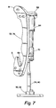
- FIG. seven shows the two way hinge in top view open.
- FIG. eight shows a cross section view of a piston assembly.
- FIG. nine shows a cross section view of an upper attach point of the piston assembly.
- FIG. ten shows a cross section view of a lower attach point of the piston assembly.
- FIG. eleven shows a cross section view of the pivot axis of the hinge assembly.
- FIG. twelve shows a cross section view of the rotating axis of the hinge assembly.
- FIG. thirteen shows a cross section view of the sag adjuster.
- FIG. fourteen shows an exploded view of the pivot plate and associated components.
- FIG. fifteen shows the fender guard.
- the vehicle door hinge assembly ( 2 ) has a fender mount ( 4 ) the fender mount ( 4 ) being generally goose neck shaped and having a convex portion ( 74 ) and a concave portion ( 76 ).
- the fender mount ( 4 ) has a first hole positioning plate ( 6 ) and a second hole positioning plate ( 8 ) defined thereon.
- the first and second hole positioning plates ( 6 , 8 ) are positionally opposed to each other and allow for easy positioning to a chassis of a motor vehicle.
- the first hole positioning plate ( 6 ) and the second hole positioning plate ( 8 ) compnsing a fender mount assembly ( 52 ).
- the first hole positioning plate ( 6 ) has a first series of through holes ( 10 ) defined therein.
- the second hole positioning plate ( 8 ) has a second series of through holes ( 12 ) defined therein.
- the first and second series of through holes ( 10 , 12 ) are positioned to use the existing holes located in the particular motor vehicle's fender.
- the existing holes that the fender mount assembly ( 52 ) use are those that the particular motor vehicle use to attach the factory hinge.
- a first boss ( 14 ) and a second boss ( 16 ) are located towards an upper portion ( 18 ) of the first fender mount ( 4 ), and are spaced in a parallel relationship to allow a pivot plate ( 20 ) to be spaced therebetween.
- the first boss ( 14 ) has a first hole ( 22 ) defined therein
- the second boss ( 16 ) has a second hole ( 24 ) defined therein.
- the first hole ( 22 ) and the second hole ( 24 ) of the first and second boss ( 14 , 16 ) respectfully, are axially aligned, allowing for a first and second threaded pin ( 26 , 27 ) to be inserted therethrough.
- the first threaded pin ( 26 ) and second threaded pin ( 27 ) each have bearings ( 72 ) located thereon to allow effortless rotation of the pivot plate ( 20 ).
- the bearings ( 72 ) on the first and second threaded pins ( 26 , 27 ) are installed in the first hole ( 22 ) of the first boss ( 14 ), and the second hole ( 24 ) of the second boss ( 16 ) respectfully.
- the pivot plate ( 20 ) has a third through hole ( 28 ) defined therein.
- the third through hole ( 28 ) is located in a transverse direction ( 44 ) on the pivot plate ( 20 ).
- a first door plate ( 30 ) and a second door plate ( 32 ) are positionally located by a door bracket ( 34 ) the first door plate ( 30 ) and the second door plate ( 32 ) being fixedly attached to the door bracket ( 34 ) to fix the first and second door plates ( 30 , 32 ) for their intended use.
- the first door plate ( 30 ) has a third series of holes ( 36 ) defined therein, and the second door plate ( 32 ) has a fourth series of holes ( 38 ) defined therein.
- the third and fourth series of holes ( 36 , 38 ) are defined by the particular vehicle's “OEM” hinge location.
- the first door plate ( 30 ) the second door plate ( 32 ), and the door bracket ( 34 ) comprise the door mount assembly ( 40 ).
- the door bracket ( 34 ) being shaped to fit within the concave portion ( 76 ) of the fender mount assembly ( 52 ).
- the door mount assembly ( 40 ) is fixedly attached to a door hinge bracket ( 42 ).
- the door hinge bracket ( 42 ) is essentially an “L” shaped member that extends to the upper portion ( 18 ) of the first fender mount ( 4 ).
- a fender guard ( 80 ) is threadably attached to the fender mount assembly ( 52 ) in close proximity to the door bracket ( 34 ) to prevent damage to a motor vehicle fender when the vehicle door has not been opened the necessary 20° (degrees) in the horizontal plane.
- the pivot plate ( 20 ) has a counterbore ( 46 ) defined therein, the counterbore being axially aligned to the third hole ( 28 ) defining a stepped hole ( 47 ) thereby.
- the stepped hole ( 47 ) is located in a short transverse direction ( 48 ) on the pivot plate ( 20 ).
- the stepped hole ( 47 ) in the pivot plate ( 20 ) allows a third threaded pivot pin ( 50 ) to be inserted therethrough, and threadably engage the door mount assembly ( 40 ) in a rotatable motional relationship with the door mounting assembly ( 40 ).
- the third threaded pivot pin ( 50 ) has a third bearing ( 51 ) attached thereon, where the third bearing is positioned in the counterbore ( 46 ) of the stepped hole ( 47 ).
- the pivot plate ( 20 ) now is rotatably positioned about the third threaded pivot pin ( 50 ).
- the pivot plate ( 20 ) has a beveled portion ( 54 ) defined thereon.
- the beveled portion ( 54 ) of the pivot plate ( 20 ) faces the fender mount assembly ( 54 ) and prevents rotation of the door mounting assembly ( 40 ) greater than a predefined bevel angle, here defined as 20° (degrees).
- a third boss or sag plate ( 56 ) is attached to the pivot plate ( 20 ).
- a sag adjuster boss ( 58 ) is attached to the door mount assembly ( 40 ).
- the sag adjuster boss ( 58 ) has a threaded hole ( 60 ) defined therein.
- the sag plate ( 56 ) has a face ( 61 ), where the face ( 61 ) allows a sag adjusting means ( 62 ) to bear against it.
- the sag adjusting means ( 62 ) threadably inserted through the sag adjuster boss ( 58 ).
- a piston assembly ( 64 ) is medially attached to the fender mount assembly ( 52 ) and also attached to the door mount assembly ( 40 ).
- a piston mounting plate ( 66 ) is attached to the fender mount assembly ( 52 ).
- the piston mounting plate ( 66 ) has a hole ( 67 ) defined therein wherein the hole ( 67 ) has a spherical bearing ( 68 ) fixedly attached therein.
- the spherical bearing ( 68 ) is a standard known in the industry.
- the piston assembly ( 64 ) is inserted through spherical bearing ( 68 ) and fixedly attached thereon, allowing the piston assembly ( 64 ) to freely rotate within the confines of the spherical bearing ( 68 ).
- a piston attach bracket ( 82 ) has a threaded hole ( 94 ) defined therein. An opposing end ( 70 ) of the piston assembly ( 64 ) is threadably inserted into the threaded hole ( 94 ) of the piston attach bracket ( 82 ).
- the piston attach bracket is generally an “L” shaped component.
- a washer ( 96 ) bears against the piston attach bracket ( 82 ) and the piston assembly ( 64 ).
- the piston attach bracket ( 82 ) is mounted medially between the lugs of a piston attach clevis ( 84 ).
- An industry standard bolt ( 86 ) is pivotably inserted through the piston attach bracket ( 82 ) and the lugs of the piston attach clevis ( 84 ) and threadably engaged into i the fender mount assembly ( 52 ).
- An securing screw ( 92 ) is inserted through the fender mount assembly ( 52 ) and is threadably inserted into the piston attach clevis ( 84 ) securing the piston attach clevis ( 84 ) to the fender mount assembly ( 52 ). using a nut and bolt means common in the industry.
- the door is opened in the following manner.
- the user unlocks the door and rotates the door in a horizontal plane approximately 20°, the horizontal plane being defined by the axially aligned holes ( 22 , 24 ) in the first and second bosses ( 14 , 16 ).
- the user can then rotate the door upwards, the roatating axis being defined by the third threaded pivot pin ( 50 ).
- the maximum rotational displacement being 45°.
- the piston assembly ( 64 ) providing assistance to the user in providing a force to keep the door of the motor vehicle open.
Abstract
This invention describes a novel two way hinge for motor vehicle doors that hinges open at a 20 degree angle, then rotates upward 45 degrees. The motor vehicle door is maintained in the open position by a shock absorber/piston arrangement that is common in the automotive industry. The invention described herein can be installed by an aftermarket shop and/or sold as an easily installed kit. The present invention overcomes the shortcomings of existing hinges by allowing greater access for ingress and egress from existing motor vehicle doors in tight parking situations.
Description
The present invention relates to novel hinge assembly for automobiles, trucks and the like, and more particularly to passenger and drivers doors that typically are hinged to only open outwards.
In order to ingress or egress from automobiles or other vehicles that have drivers and may carry passengers, the automotive manufactures have added doors. Generally the doors are mounted on a single hinge, where one half of the hinge is mounted onto the vertical door post of the body of the car, and the other half of the hinge is mounted onto a generally parallel door structure. This allows the hinge to open the door by swinging away from the vehicle, thereby providing an adequate amount of opening to exit the vehicle, since smaller vehicles have much smaller exit openings than the larger vehicles. Since automobiles and trucks are essentially rectangular in shape, the most common method of providing doors is to mount the hinge on a forward vertical edge of the door, allowing the trailing edge of the door to swing outwards and forward.
With the advent of more modern vehicles, the manufacturers have incorporated aerodynamic shapes in order top provide a more fuel efficient and a more aesthetically pleasing shape to the vehicle. Safety engineers have also had major input into the design of the doors, in order to provide the maximum amount of safety both pre and post collision. One of the most glaring negative aspects of having doors open along the vertical forward edge of the door is that a large amount of room is needed in order to swing the door open to it's greatest opening area.
There have been many efforts to revise the opening method of automobile doors not only for aesthetic purposes, but also for safety, in order to provide improved ingress and egress for passengers. In an effort to modernize the door assemblies to more effectively accommodate the complexity and sophistication of modern automotive and truck design, some manufacturers have incorporated non-standard door assemblies.
Mercedes, and BMW have incorporated the “Gull wing” designs into a limited number of their vehicle designs. Delorean has also incorporated a non-standard door assembly, by allowing the door to rotate along its top edge to provide an opening for the driver and passenger. The Lamborghini Countach has doors which pivot vertically about the top forward edge of the doors. These doors, however, were only used in show cars and a small number of limited production cars.
The present invention is a two way hinge, where one flange of the hinge is mounted onto a hard point on the fender walls of the vehicle. A second flange is mounted onto the vertical door sill. The second flange is rotatably and hingeably mounted to the first flange such that the door hinges open 45 degrees, and then rotates upwards 20 degrees. The door is maintained in an open position by a standard shock/piston arrangement. The piston also reduces the amount of force needed to open the door.
The present invention also overcomes some of the shortcomings of existing hinges by allowing greater access for ingress and egress from existing automobiles and trucks, particularly in tight parking spaces.
The present invention provides a much more pleasing aesthetic vehicle which mimics more expensive vehicles such as the Lamborghini, Mercedes and Delorean at a greatly reduced per vehicle cost.
The present invention may be installed by an aftermarket shop, or person, and be sold as an easily installed kit. Alternatively, it may be installed by the manufacturer as an alternative to the existing hinge methods.
U.S. Pat. No. 4,801,172 by Townsend, discloses a Vehicle closure. This patent is generally designed for vehicles that are aerodynamically designed, and therefore have highly curved shapes. The door assembly is slidably mounted onto the vehicle and is rotatably moveable within the curved exterior about a series of arcs, where the door slides underneath the vehicle.
U.S. Pat. No. 6,086,137 by Leschke et al. Discloses a “Side Door of a Passenger Vehicle”. This invention is based upon a singular pivot hinge that is geometrically mounted on the body work, typically the front fender area. The pivot is normally a bearing and allows for quick release from the A pillar of a vehicle. The operation of the mechanism allows for a rotation away from the vehicle prior to the rotation upwards. The basic differences between the present invention and the Leschke patent are that the present invention is specifically designed for a variety of vehicles and would be installed as an after market arrangement by either the owner or a shop. The design of the Leschke patent is such that the vehicle manufacture must install the hinge mechanism and also must design the door and body structure to accommodate the hinge.
U.S. Pat. No. 3,589,069 by Lecomte discloses a “Vehicle Door Mounting”. This invention allows a door to rotate about a single fixed pivot shaft. The design of the Lecomte patent design allows the door to rotate open, but also the door translates outward along the hinge axis during the rotational motion. This is a discrete type of singular motion, in that only during rotation is the door forced to translate away from the bodywork of the vehicle. A shortcoming this patent is that the hinge system can only be accommodated by specific body shapes, and can not be easily accommodated with a large variety of automobiles or trucks in the open market.
FIG. one shows a front view of a motor car with the doors open.
FIG. two shows a rear view of a motor car with the doors open.
FIG. three shows the two way hinge in a closed position.
FIG. four shows the two way hinge in an open position.
FIG. five shows the two way hinge in edge view closed.
FIG. six shows the two way hinge in edge view open.
FIG. seven shows the two way hinge in top view open.
FIG. eight shows a cross section view of a piston assembly.
FIG. nine shows a cross section view of an upper attach point of the piston assembly.
FIG. ten shows a cross section view of a lower attach point of the piston assembly.
FIG. eleven shows a cross section view of the pivot axis of the hinge assembly.
FIG. twelve shows a cross section view of the rotating axis of the hinge assembly.
FIG. thirteen shows a cross section view of the sag adjuster.
FIG. fourteen shows an exploded view of the pivot plate and associated components.
FIG. fifteen shows the fender guard.
With respect to figures one through fifteen, what is herein disclosed and described is a vehicle door hinge assembly (2). The vehicle door hinge assembly (2) has a fender mount (4) the fender mount (4) being generally goose neck shaped and having a convex portion (74) and a concave portion (76). The fender mount (4) has a first hole positioning plate (6) and a second hole positioning plate (8) defined thereon. The first and second hole positioning plates (6, 8) are positionally opposed to each other and allow for easy positioning to a chassis of a motor vehicle. The first hole positioning plate (6) and the second hole positioning plate (8) compnsing a fender mount assembly (52). The first hole positioning plate (6) has a first series of through holes (10) defined therein. The second hole positioning plate (8) has a second series of through holes (12) defined therein. The first and second series of through holes (10, 12) are positioned to use the existing holes located in the particular motor vehicle's fender. The existing holes that the fender mount assembly (52) use are those that the particular motor vehicle use to attach the factory hinge.
A first boss (14) and a second boss (16) are located towards an upper portion (18) of the first fender mount (4), and are spaced in a parallel relationship to allow a pivot plate (20) to be spaced therebetween. The first boss (14) has a first hole (22) defined therein, and the second boss (16) has a second hole (24) defined therein. The first hole (22) and the second hole (24) of the first and second boss (14, 16) respectfully, are axially aligned, allowing for a first and second threaded pin (26, 27) to be inserted therethrough. The first threaded pin (26) and second threaded pin (27) each have bearings (72) located thereon to allow effortless rotation of the pivot plate (20). The bearings (72) on the first and second threaded pins (26, 27) are installed in the first hole (22) of the first boss (14), and the second hole (24) of the second boss (16) respectfully. The pivot plate (20) has a third through hole (28) defined therein. The third through hole (28) is located in a transverse direction (44) on the pivot plate (20).
A first door plate (30) and a second door plate (32) are positionally located by a door bracket (34) the first door plate (30) and the second door plate (32) being fixedly attached to the door bracket (34) to fix the first and second door plates (30, 32) for their intended use. The first door plate (30) has a third series of holes (36) defined therein, and the second door plate (32) has a fourth series of holes (38) defined therein. The third and fourth series of holes (36, 38) are defined by the particular vehicle's “OEM” hinge location. The first door plate (30) the second door plate (32), and the door bracket (34) comprise the door mount assembly (40). The door bracket (34) being shaped to fit within the concave portion (76) of the fender mount assembly (52). The door mount assembly (40) is fixedly attached to a door hinge bracket (42). The door hinge bracket (42) is essentially an “L” shaped member that extends to the upper portion (18) of the first fender mount (4). A fender guard (80) is threadably attached to the fender mount assembly (52) in close proximity to the door bracket (34) to prevent damage to a motor vehicle fender when the vehicle door has not been opened the necessary 20° (degrees) in the horizontal plane.
The pivot plate (20) has a counterbore (46) defined therein, the counterbore being axially aligned to the third hole (28) defining a stepped hole (47) thereby. The stepped hole (47) is located in a short transverse direction (48) on the pivot plate (20). The stepped hole (47) in the pivot plate (20) allows a third threaded pivot pin (50) to be inserted therethrough, and threadably engage the door mount assembly (40) in a rotatable motional relationship with the door mounting assembly (40). The third threaded pivot pin (50) has a third bearing (51) attached thereon, where the third bearing is positioned in the counterbore (46) of the stepped hole (47). The pivot plate (20) now is rotatably positioned about the third threaded pivot pin (50).
The pivot plate (20) has a beveled portion (54) defined thereon. The beveled portion (54) of the pivot plate (20) faces the fender mount assembly (54) and prevents rotation of the door mounting assembly (40) greater than a predefined bevel angle, here defined as 20° (degrees). A third boss or sag plate (56) is attached to the pivot plate (20). A sag adjuster boss (58) is attached to the door mount assembly (40). The sag adjuster boss (58) has a threaded hole (60) defined therein. The sag plate (56) has a face (61), where the face (61) allows a sag adjusting means (62) to bear against it. The sag adjusting means (62) threadably inserted through the sag adjuster boss (58).
A piston assembly (64) is medially attached to the fender mount assembly (52) and also attached to the door mount assembly (40). A piston mounting plate (66) is attached to the fender mount assembly (52). The piston mounting plate (66) has a hole (67) defined therein wherein the hole (67) has a spherical bearing (68) fixedly attached therein. The spherical bearing (68) is a standard known in the industry. The piston assembly (64) is inserted through spherical bearing (68) and fixedly attached thereon, allowing the piston assembly (64) to freely rotate within the confines of the spherical bearing (68). An opposing end (70) of the piston assembly (64) is mechanically attached to the door mounting assembly (40). A piston attach bracket (82) has a threaded hole (94) defined therein. An opposing end (70) of the piston assembly (64) is threadably inserted into the threaded hole (94) of the piston attach bracket (82). The piston attach bracket is generally an “L” shaped component. A washer (96) bears against the piston attach bracket (82) and the piston assembly (64). The piston attach bracket (82) is mounted medially between the lugs of a piston attach clevis (84). An industry standard bolt (86) is pivotably inserted through the piston attach bracket (82) and the lugs of the piston attach clevis (84) and threadably engaged into i the fender mount assembly (52). An securing screw (92) is inserted through the fender mount assembly (52) and is threadably inserted into the piston attach clevis (84) securing the piston attach clevis (84) to the fender mount assembly (52). using a nut and bolt means common in the industry.
The door is opened in the following manner. The user unlocks the door and rotates the door in a horizontal plane approximately 20°, the horizontal plane being defined by the axially aligned holes (22, 24) in the first and second bosses (14, 16). The user can then rotate the door upwards, the roatating axis being defined by the third threaded pivot pin (50). The maximum rotational displacement being 45°. The piston assembly (64) providing assistance to the user in providing a force to keep the door of the motor vehicle open.
Although the foregoing includes a description of the best mode contemplated for carrying out the invention, various modifications are contemplated.
As various modifications could be made in the constructions herein described and illustrated without departing from the scope of the invention, it is intended_that all matter contained in the foregoing description or shown in the accompanying drawings shall be interpreted as illustrative rather than limiting.
Claims (6)
1. A two way hinge for motor vehicle doors, comprising:
a. a fender mount, said fender mount being generally goose neck shaped and having a convex portion and a concave portion, said fender mount further having a first hole positioning plate and a second hole positioning plate, said first hole positioning plate and said second hole positioning plate being positionally opposed to each other, said first hole positioning plate having a first series of holes defined therein, said second hole positioning plate having a second series of holes defined therein, said first and second series of holes being positionally located to correspond to the particular vehicle being installed therein, said fender mount, said first hole positioning plate, and said second hole positioning plate comprising a fender mount assembly;
b. a first boss and a second boss being aligned in a parallel relationship and being positioned on an upper portion of said fender mount assembly, said first boss having a first hole defined therein, said second boss having a second hole defined therein, said first and said second hole being axially aligned, a pivot plate, said pivot plate being positioned between said first and said second boss;
c. a first threaded pin, said first threaded pin being inserted through said first hole in said first boss and being threadably engaged in said pivot plate, a second threaded pin, said second threaded pin being inserted through said second hole in said second boss and being threadably engaged in said pivot plate, said first and said second threaded pin allowing said pivot plate to pivot about axially aligned holes, said pivot plate having a third through hole defined therein, said third through hole having a counterbore defined therein, said counter bore being located on a short transverse position of said pivot plate;
d. a first door plate and a second door plate are positionally located by a door bracket, said first door plate and said second door plate being fixedly attached to said door bracket, said first door plate, said second door plate and said door bracket comprise a door mount assembly, said door mount assembly being shaped to fit within said concave portion of said fender mount assembly, said door hinge bracket being essentially an L shaped bracket, said door hinge bracket mounting to a motor vehicle door frame;
e. a fender guard, said fender guard being located in proximity to said first hole positioning plate, said fender guard preventing a motor vehicle door from damaging the sheet metal of a motor vehicle;
f. a third pivot pin, said third pivot pin being inserted into said counterbored hole in said pivot plate, said third pivot pin being attached to said door mount assembly and allowing said pivot plate to rotate about said third pivot pin;
g. said pivot plate having a beveled portion defined thereon, said beveled portion defining the horizontal rotational angle of the two way hinge;
h. a sag adjuster means, said sag adjuster means allowing the vehicle door to be positionally aligned in the motor vehicle thereby; and
i. a piston mounting plate, said piston mounting plate being attached to said fender mount assembly, said piston mounting plate having a hole defined therein, a spherical bearing is fixedly attached therein, a piston assembly is inserted through said spherical bearing and fixedly attached thereon, an opposing end of said piston assembly is rotatably attached to said door mounting assembly.
2. The two way hinge for motor vehicle doors of claim one wherein said first and said second threaded pins each have a bearing attached thereon, said bearings being inserted through said first and said second holes of said first and said second bosses respectfully.
3. The two way hinge for motor vehicle doors of claim one wherein said third pin is threadably engaged into said door mount assembly.
4. The two way hinge for motor vehicle doors of claim one wherein said third threaded pin has a bearing attached thereon, said bearing being inserted into said counterbore portion of said counterbored hole of said pivot plate.
5. The two way hinge for motor vehicle doors of claim one wherein said sag adjuster means comprises a sag adjuster plate, said sag adjuster plate being attached to said pivot plate, a sag adjuster boss, said sag adjuster boss being attached to said door mount assembly, said sag adjuster boss having a threaded hole defined therein, said sag adjuster means is threadably inserted through said threaded hole in said sag adjuster boss and allows the sag adjuster means to bear on a face of said sag plate.
6. The two way hinge for motor vehicle doors of claim one, wherein, said two way hinge allowing the motor vehicle door to rotate outwards from the vehicle approximately twenty degrees firstly, clearing said fender guard thereby, then said two way hinge allowing the motor vehicle door to pivot upwards forty five degrees secondly providing easy ingress and egress from the motor vehicle.
Priority Applications (2)
| Application Number | Priority Date | Filing Date | Title |
|---|---|---|---|
| US10/756,921 US6808223B1 (en) | 2004-01-14 | 2004-01-14 | Two way hinge for motor vehicle doors |
| US11/113,338 USRE42492E1 (en) | 2004-01-14 | 2005-04-22 | Two way hinge for motor vehicle doors |
Applications Claiming Priority (1)
| Application Number | Priority Date | Filing Date | Title |
|---|---|---|---|
| US10/756,921 US6808223B1 (en) | 2004-01-14 | 2004-01-14 | Two way hinge for motor vehicle doors |
Related Child Applications (1)
| Application Number | Title | Priority Date | Filing Date |
|---|---|---|---|
| US11/113,338 Reissue USRE42492E1 (en) | 2004-01-14 | 2005-04-22 | Two way hinge for motor vehicle doors |
Publications (1)
| Publication Number | Publication Date |
|---|---|
| US6808223B1 true US6808223B1 (en) | 2004-10-26 |
Family
ID=33160099
Family Applications (2)
| Application Number | Title | Priority Date | Filing Date |
|---|---|---|---|
| US10/756,921 Ceased US6808223B1 (en) | 2004-01-14 | 2004-01-14 | Two way hinge for motor vehicle doors |
| US11/113,338 Expired - Fee Related USRE42492E1 (en) | 2004-01-14 | 2005-04-22 | Two way hinge for motor vehicle doors |
Family Applications After (1)
| Application Number | Title | Priority Date | Filing Date |
|---|---|---|---|
| US11/113,338 Expired - Fee Related USRE42492E1 (en) | 2004-01-14 | 2005-04-22 | Two way hinge for motor vehicle doors |
Country Status (1)
| Country | Link |
|---|---|
| US (2) | US6808223B1 (en) |
Cited By (41)
| Publication number | Priority date | Publication date | Assignee | Title |
|---|---|---|---|---|
| WO2004048138A2 (en) * | 2002-11-26 | 2004-06-10 | Mcrobert Eric L | Method and apparatus for attaching a door to a passenger vehicle |
| US20040187263A1 (en) * | 2003-03-25 | 2004-09-30 | Hoffman Lawrence Andrew | Multi-axis door hinge and swing-out vertical-lift assembly |
| US20040244144A1 (en) * | 2002-05-20 | 2004-12-09 | Demetrius Ham | Vertical door conversion kit with lag mechanism and motion range limiter |
| US20050057070A1 (en) * | 2003-09-16 | 2005-03-17 | Kyung-Dug Seo | Door hinge mounting structure for vehicles |
| US20050116497A1 (en) * | 2003-11-28 | 2005-06-02 | Debono Joseph M. | Door lift conversion kit for existing vehicles |
| US20050166363A1 (en) * | 2003-03-25 | 2005-08-04 | Hoffman Lawrence A. | Multi-axis door hinge |
| US20050204511A1 (en) * | 2004-03-17 | 2005-09-22 | Klaus Wohlfarth | Hinge for a motor-vehicle door |
| US20050285429A1 (en) * | 2004-06-28 | 2005-12-29 | Guy Valois | Automated car door opening system |
| US20060123592A1 (en) * | 2004-12-15 | 2006-06-15 | Johnnie Yip | Adjustable hinge for a motor vehicle |
| US20070013208A1 (en) * | 2004-10-15 | 2007-01-18 | Spencer Krumholz | Adjustable door kit assembly |
| WO2007019829A1 (en) * | 2005-08-18 | 2007-02-22 | Mario Lau | Two way hinge |
| US20070126260A1 (en) * | 2005-07-18 | 2007-06-07 | Mattias Geyrhofer | Vehicle door opening system |
| US20070214606A1 (en) * | 2005-02-11 | 2007-09-20 | Hoffman Lawrence A | Simultaneous, multiple plane opening hinge |
| US20070245525A1 (en) * | 2003-03-25 | 2007-10-25 | The Hoffman Group, Llc | Multi-axis door hinge |
| US20080079284A1 (en) * | 2006-09-29 | 2008-04-03 | Heriberto Moreno | Door mechanism |
| US20080083089A1 (en) * | 2006-10-04 | 2008-04-10 | The Hoffman Group International, Ltd. | Multi-axis door hinge |
| US7396068B1 (en) * | 2002-11-26 | 2008-07-08 | Mcrobert Eric L | Method and apparatus for attaching a door to a passenger vehicle |
| US20090056074A1 (en) * | 2007-08-28 | 2009-03-05 | Chase Daniel A | Automobile door hinge |
| US20090106940A1 (en) * | 2007-10-30 | 2009-04-30 | Dan Greenbank | Dual Stage Hidden Hinge |
| US20090106941A1 (en) * | 2007-10-30 | 2009-04-30 | Dan Greenbank | Biaxial Door Hinge |
| US20090106936A1 (en) * | 2007-10-30 | 2009-04-30 | Dan Greenbank | Pillar Mounted Vehicle Hinge |
| US7591504B1 (en) * | 2008-09-05 | 2009-09-22 | Honda Motor Co., Ltd. | Passenger door relocation system and method |
| US20090295187A1 (en) * | 2008-05-29 | 2009-12-03 | Demetrius Calvin Ham | Car door hinge |
| US20100269299A1 (en) * | 2009-04-24 | 2010-10-28 | Johnnie Yip | Front door hinge |
| US20100269301A1 (en) * | 2009-04-24 | 2010-10-28 | Johnnie Yip | Reversible door hinge |
| US20110030171A1 (en) * | 2009-08-06 | 2011-02-10 | Gm Global Technology Operations, Inc. | Multiple Axis Hinge for a Vehicle Body Side Door |
| US20110035903A1 (en) * | 2009-08-11 | 2011-02-17 | Jeremy Thomas Sims | Hinge And Spring Assembly |
| US7941897B1 (en) | 2002-05-20 | 2011-05-17 | Vertical Doors, Inc. | Vertical door conversion kit |
| FR2953769A3 (en) * | 2009-12-15 | 2011-06-17 | Renault Sa | Casement i.e. front lateral door, for motor vehicle, has hinge forming unit mounted moving between folded position in which rotation axis is closer to structure and deployed position in which rotation axis is far away from structure |
| US7963001B2 (en) * | 2009-04-24 | 2011-06-21 | Johnnie Yip | Door hinge |
| USRE42492E1 (en) | 2004-01-14 | 2011-06-28 | Vertical Doors, Inc. | Two way hinge for motor vehicle doors |
| US8186013B2 (en) * | 2009-04-24 | 2012-05-29 | Johnnie Yip | Double motion door hinge for motor vehicles |
| US8291548B2 (en) * | 2009-04-24 | 2012-10-23 | Johnnie Yip | Diagonal opening hinge |
| CZ304811B6 (en) * | 2013-09-26 | 2014-11-05 | Přemysl Baláž | Automobile tailgate apparatus |
| US20140325792A1 (en) * | 2013-05-06 | 2014-11-06 | Klaus Wohlfarth | Hinge Device For A Motor Vehicle Door |
| US20180030764A1 (en) * | 2016-07-27 | 2018-02-01 | Ford Global Technologies, Llc | Motor vehicle and a door hinge mechanism therefor |
| US20180171691A1 (en) * | 2016-12-16 | 2018-06-21 | Hyundai Motor Company | Apparatus, system, and method for separating vehicle door in emergency |
| NL2025794B1 (en) | 2020-06-09 | 2022-01-28 | Van Den Eijnden Quinten | Vehicle equipped with improved door hinge |
| CN114059869A (en) * | 2021-12-23 | 2022-02-18 | 上海安宇峰实业有限公司 | Hinge structure of automobile door |
| US20220119045A1 (en) * | 2020-07-02 | 2022-04-21 | Magna Exteriors Inc. | Bed sidegate |
| US11660940B2 (en) | 2019-04-05 | 2023-05-30 | Karma Automotive Llc | Multi-axis hinge for a stylized vehicle door |
Families Citing this family (2)
| Publication number | Priority date | Publication date | Assignee | Title |
|---|---|---|---|---|
| US6366087B1 (en) * | 1998-10-30 | 2002-04-02 | George Richard Coates | NMR logging apparatus and methods for fluid typing |
| TWM513047U (en) * | 2015-08-17 | 2015-12-01 | Entropy Prec System Inc | Pivoting apparatus for lifting faceplate of gaming machine |
Citations (10)
| Publication number | Priority date | Publication date | Assignee | Title |
|---|---|---|---|---|
| US3589069A (en) | 1969-03-10 | 1971-06-29 | Renault | Vehicle door mounting |
| US4684167A (en) | 1986-09-26 | 1987-08-04 | Newmayer Ricky L | Roof hinged door apparatus |
| US4719665A (en) | 1986-12-11 | 1988-01-19 | General Motors Corporation | Double pivot hinge |
| US4801172A (en) | 1985-10-03 | 1989-01-31 | Townsend John A | Vehicle closure |
| US5035463A (en) | 1989-09-26 | 1991-07-30 | Ohi Seisakusho Co., Ltd. | Roof door device of motor vehicle |
| US6000747A (en) | 1998-08-10 | 1999-12-14 | Ford Global Technologies, Inc. | Vehicle liftgate and flipglass with a shared hinge axis |
| US6086137A (en) | 1996-09-27 | 2000-07-11 | Daimlerchrysler Ag | Side door of a passenger vehicle |
| US6175991B1 (en) | 1998-09-14 | 2001-01-23 | Ford Global Technologies, Inc. | Articulated door hinge for an automotive vehicle |
| US20030213102A1 (en) | 2002-05-20 | 2003-11-20 | Ham Demetrius Calvin | Vertical door conversion kit |
| US6676193B1 (en) * | 2003-01-13 | 2004-01-13 | Corbin Pacific, Inc. | Vehicle with upwardly pivoting door |
Family Cites Families (78)
| Publication number | Priority date | Publication date | Assignee | Title |
|---|---|---|---|---|
| US1065406A (en) | 1912-05-16 | 1913-06-24 | Dwight Swinford | Rotary hinged door. |
| US1241397A (en) | 1916-10-23 | 1917-09-25 | James Keith | Crucible-furnace. |
| US2200311A (en) | 1937-03-01 | 1940-05-14 | Atwood Vacuum Machine Co | Hinge |
| US2172868A (en) | 1937-06-19 | 1939-09-12 | Clarence M Elson | Fence gate |
| US2178908A (en) | 1937-10-07 | 1939-11-07 | Hudson Richard John Harrington | Hinge mounting for doors, panels, hatchways, or the like |
| US2374697A (en) | 1944-03-11 | 1945-05-01 | Charles J Palisano | Tail gate |
| US2585152A (en) | 1947-02-13 | 1952-02-12 | Jacob B Merchant | Gate |
| US2777728A (en) | 1949-09-23 | 1957-01-15 | Daimler Benz Ag | Motor vehicle accessible by means of a pivotal cap |
| US2754537A (en) | 1953-03-19 | 1956-07-17 | Rose Carl | Hinge structure |
| US2775478A (en) | 1954-01-19 | 1956-12-25 | Gen Motors Corp | Vehicle door hinge and cam |
| US2758344A (en) | 1955-01-10 | 1956-08-14 | Browne Window Mfg Company Inc | Window with stationary, pivoted and hinged frames |
| US2793069A (en) | 1956-03-05 | 1957-05-21 | Bixler George | Pivotal type vehicle cab door |
| DE1249715B (en) | 1958-03-15 | |||
| US3095600A (en) | 1960-03-18 | 1963-07-02 | Gen Motors Corp | Door hinging arrangement for vehicle bodies |
| US3150408A (en) | 1961-04-04 | 1964-09-29 | Ford Motor Co | Vehicle door hinge |
| US3275370A (en) | 1964-05-18 | 1966-09-27 | Ford Motor Co | Motor vehicle |
| US3954853A (en) | 1967-07-26 | 1976-05-04 | Eastman Kodak Company | Substituted phenoxy-3-chloro-malealdehydic acids |
| US3594853A (en) | 1969-07-28 | 1971-07-27 | Atwood Vacuum Machine Co | Automobile door hinging |
| US3628216A (en) | 1970-07-01 | 1971-12-21 | Ford Motor Co | Articulated door hinge |
| US3870361A (en) | 1973-02-12 | 1975-03-11 | Atwood Vacuum Machine Co | Hinging system for automobile doors with hinge halves welded to body and door |
| US3848293A (en) | 1973-03-19 | 1974-11-19 | Atwood Vacuum Machine Co | Dual action conical door hinge system |
| AT353135B (en) | 1973-12-12 | 1979-10-25 | Praemeta | HIDDEN, SIDE AND DEPTH-ADJUSTABLE HINGE FOR DOOR LEAF WITH AN OPENING ANGLE OF UP TO 180 DEGREES, IN PARTICULAR FURNITURE HINGES |
| US4238876A (en) | 1978-09-05 | 1980-12-16 | Gary S. Monroe | Method for converting hard top vehicles to removable top vehicles |
| DE3203276A1 (en) | 1982-02-01 | 1983-08-11 | Volkswagenwerk Ag, 3180 Wolfsburg | Hinge arrangement for a door, especially a motor-vehicle door |
| US4532675A (en) | 1982-05-17 | 1985-08-06 | Ford Motor Company | Door hinge with integral check |
| DE3238885A1 (en) | 1982-10-21 | 1984-04-26 | Wegmann & Co GmbH, 3500 Kassel | FIGHTING VEHICLE, IN PARTICULAR FIGHTING TANK |
| JPS59179972U (en) | 1983-05-17 | 1984-12-01 | トヨタ自動車株式会社 | Automobile side door hinge mechanism |
| JPS6064122U (en) | 1983-10-11 | 1985-05-07 | トヨタ自動車株式会社 | Automobile side door hinge mechanism |
| DE3341922A1 (en) | 1983-11-19 | 1985-06-20 | Audi AG, 8070 Ingolstadt | Side doors for vehicles |
| JPH0660468B2 (en) | 1984-05-16 | 1994-08-10 | 大日本印刷株式会社 | Cosmetic material |
| DE3423037A1 (en) | 1984-06-22 | 1986-01-02 | Audi AG, 8070 Ingolstadt | Hinge, especially for a three-dimensionally adjustable vehicle door |
| DE3539276C1 (en) | 1985-11-06 | 1987-01-02 | Audi Ag, 8070 Ingolstadt, De | |
| US4692964A (en) | 1986-03-05 | 1987-09-15 | Amerock Corporation | Concealed self-closing hinge |
| JPH0662062B2 (en) | 1986-08-28 | 1994-08-17 | トヨタ自動車株式会社 | Car door structure |
| US4765025A (en) | 1986-12-29 | 1988-08-23 | Ford Motor Company | Vehicle door mounting assembly for effecting vertical removability |
| US4766643A (en) | 1986-12-29 | 1988-08-30 | Ford Motor Company | Vehicle door hinge having vertically separable pivotal connections |
| US4776626A (en) | 1987-07-20 | 1988-10-11 | Perfection Spring & Stamping Corp. | Trunk lid hinge and spring assembly |
| US4852940A (en) | 1987-08-20 | 1989-08-01 | Weber Aircraft Corporation | Stowable table system |
| DE3730520C1 (en) | 1987-09-11 | 1988-06-23 | Audi Ag | Hinge arrangement of a vehicle door |
| US4881298A (en) | 1988-07-21 | 1989-11-21 | General Motors Corporation | Separable door hinge for vehicle body |
| JP2731861B2 (en) | 1989-04-28 | 1998-03-25 | 株式会社コトブキ | Emergency displacement method and device for chair entry / exit base plate |
| DE4012891A1 (en) | 1990-04-23 | 1991-10-24 | Neff Thomas | Entry door for car passengers - comprises upper and lower parts, upper part being separable from vehicle body work by easily releasable throw-off hinges |
| US5013082A (en) | 1990-07-26 | 1991-05-07 | General Motors Corporation | Door opening system |
| US5074609A (en) | 1990-07-30 | 1991-12-24 | General Motors Corporation | Adjustable deck lid hinge pivot |
| FR2670719B1 (en) | 1990-12-21 | 1993-02-19 | Renault | PIVOTING SIDE DOOR OF MOTOR VEHICLE. |
| US5150500A (en) | 1991-07-11 | 1992-09-29 | Southco, Inc. | Adjustable lift-off hinge |
| US5184422A (en) | 1991-12-10 | 1993-02-09 | American Ingredients Company | Swing away manway assembly |
| US5265311A (en) | 1991-12-16 | 1993-11-30 | Econo Max Manufacturing | Self closing hinge |
| US5242208A (en) | 1991-12-27 | 1993-09-07 | Mazda Motor Corporation | Structure of a body of an automotive vehicle |
| DE4206288A1 (en) | 1992-02-28 | 1993-09-02 | Strosek Auto Design Gmbh | Gull-wing type side door for motor vehicle - is hinged to sloping portion instead of upright of door frame, and held open by gas-pressure spring at forward end |
| US5211437A (en) | 1992-07-08 | 1993-05-18 | Gerulf Dennis R | Combination tailgate and ramp assembly |
| JPH0624245A (en) | 1992-07-09 | 1994-02-01 | Toyota Autom Loom Works Ltd | Door structure for automobile |
| US5921611A (en) | 1992-07-13 | 1999-07-13 | Joalto Design Inc. | Upwardly retracting vehicle door |
| FR2694244B1 (en) | 1992-07-30 | 1994-10-14 | Matra Automobile | Motor vehicle for transporting people, with pivoting side doors. |
| DE4227411A1 (en) | 1992-08-19 | 1994-02-24 | Opel Adam Ag | Foldable side door for vehicle - has hinge axis running along carriage column above seat belt line and has fold axis below belt line about which door sections fold |
| US5261720A (en) | 1992-11-27 | 1993-11-16 | Lomax Jr Paul | Vertically moving vehicle door |
| FR2699126B1 (en) | 1992-12-11 | 1995-02-24 | Peugeot | Motor vehicle side door and motor vehicle equipped with such a door. |
| DE4319662A1 (en) | 1993-06-14 | 1994-12-15 | Edgar Bach | Side door which can be pivoted upwards for passenger cars, in particular for subsequent installation |
| US5547247A (en) | 1994-08-16 | 1996-08-20 | Burns Aerospace Corporation | Passenger tray table with ingress/egress position |
| US5600868A (en) | 1995-03-07 | 1997-02-11 | Santa Barbara Research Center | Deployment hinge |
| US5570498A (en) | 1995-05-02 | 1996-11-05 | General Motors Corporation | Lift-off door hinge |
| SE505897C2 (en) | 1996-01-08 | 1997-10-20 | Kanerva Pentti | Hinge mechanism for car doors |
| DE19626704A1 (en) | 1996-07-03 | 1998-01-08 | Scharwaechter Gmbh Co Kg | Motor vehicle door arrester |
| US6036256A (en) | 1996-10-22 | 2000-03-14 | Chrysler Corporation | Window assembly for a motor vehicle |
| FR2764245B1 (en) | 1997-06-06 | 1999-07-30 | Renault | IMPROVED DEVICE FOR JOINING A SUNREST MOUNTED PIVOTING ON THE BODY OF A MOTOR VEHICLE |
| DE19738825A1 (en) | 1997-09-05 | 1999-03-18 | Daimler Benz Ag | Motor vehicle door opening by swiveling forwards and upwards |
| US6314615B1 (en) | 1997-09-30 | 2001-11-13 | Tiete O. Wolda | Closure hinge |
| US5992918A (en) | 1998-05-07 | 1999-11-30 | General Motors Corporation | Bi-fold gull wing vehicle door |
| US6220658B1 (en) | 1998-10-16 | 2001-04-24 | Johnson Controls Technology Company | Retractable tray table |
| US6178593B1 (en) | 1998-10-23 | 2001-01-30 | Robert J. Carlson | Vertical pin automobile door hinge wear compensator |
| US6147222A (en) | 1999-12-27 | 2000-11-14 | Bayer Corporation | Process for the manufacture of sulfonylaminocarbonyl triazolinones and salts thereof under pH controlled conditions |
| DE10025925B4 (en) | 2000-05-25 | 2015-04-02 | Bayerische Motoren Werke Aktiengesellschaft | Side door of a motor vehicle |
| SE520365C2 (en) | 2000-06-21 | 2003-07-01 | Scania Cv Publ | Connection for a front door in a motor vehicle |
| US6447043B1 (en) | 2001-01-09 | 2002-09-10 | M & C Corporation | Vehicle closure assembly with hinge |
| US6629337B2 (en) | 2001-11-28 | 2003-10-07 | Edscha Roof Systems Inc. | Double-pivot resistance hinge for motor vehicle door |
| US20040256882A1 (en) | 2002-11-26 | 2004-12-23 | Mcrobert Eric L. | Method and apparatus for attaching a door to a passenger vehicle |
| US6820918B1 (en) | 2003-11-28 | 2004-11-23 | Debono Joseph M. | Door lift conversion kit for existing vehicles |
| US6808223B1 (en) | 2004-01-14 | 2004-10-26 | Robert Baum | Two way hinge for motor vehicle doors |
-
2004
- 2004-01-14 US US10/756,921 patent/US6808223B1/en not_active Ceased
-
2005
- 2005-04-22 US US11/113,338 patent/USRE42492E1/en not_active Expired - Fee Related
Patent Citations (10)
| Publication number | Priority date | Publication date | Assignee | Title |
|---|---|---|---|---|
| US3589069A (en) | 1969-03-10 | 1971-06-29 | Renault | Vehicle door mounting |
| US4801172A (en) | 1985-10-03 | 1989-01-31 | Townsend John A | Vehicle closure |
| US4684167A (en) | 1986-09-26 | 1987-08-04 | Newmayer Ricky L | Roof hinged door apparatus |
| US4719665A (en) | 1986-12-11 | 1988-01-19 | General Motors Corporation | Double pivot hinge |
| US5035463A (en) | 1989-09-26 | 1991-07-30 | Ohi Seisakusho Co., Ltd. | Roof door device of motor vehicle |
| US6086137A (en) | 1996-09-27 | 2000-07-11 | Daimlerchrysler Ag | Side door of a passenger vehicle |
| US6000747A (en) | 1998-08-10 | 1999-12-14 | Ford Global Technologies, Inc. | Vehicle liftgate and flipglass with a shared hinge axis |
| US6175991B1 (en) | 1998-09-14 | 2001-01-23 | Ford Global Technologies, Inc. | Articulated door hinge for an automotive vehicle |
| US20030213102A1 (en) | 2002-05-20 | 2003-11-20 | Ham Demetrius Calvin | Vertical door conversion kit |
| US6676193B1 (en) * | 2003-01-13 | 2004-01-13 | Corbin Pacific, Inc. | Vehicle with upwardly pivoting door |
Cited By (72)
| Publication number | Priority date | Publication date | Assignee | Title |
|---|---|---|---|---|
| US8756763B1 (en) | 2002-05-20 | 2014-06-24 | Vertical Doors, Inc. | Vertical door conversion kit |
| US7140075B2 (en) * | 2002-05-20 | 2006-11-28 | Decah, Llc | Vertical door conversion kit with lag mechanism and motion range limiter |
| US20040244144A1 (en) * | 2002-05-20 | 2004-12-09 | Demetrius Ham | Vertical door conversion kit with lag mechanism and motion range limiter |
| US7941897B1 (en) | 2002-05-20 | 2011-05-17 | Vertical Doors, Inc. | Vertical door conversion kit |
| US20050022342A1 (en) * | 2002-05-20 | 2005-02-03 | Ham Demetrius Calvin | Vertical door conversion kit |
| US20060200947A1 (en) * | 2002-05-20 | 2006-09-14 | Decah, Llc | Vertical door conversion kit |
| US7059655B2 (en) * | 2002-05-20 | 2006-06-13 | Decah, Llc | Vertical door conversion kit |
| US8151417B1 (en) | 2002-05-20 | 2012-04-10 | Vertical Doors, Inc. | Vertical door conversion kit |
| WO2004048138A2 (en) * | 2002-11-26 | 2004-06-10 | Mcrobert Eric L | Method and apparatus for attaching a door to a passenger vehicle |
| WO2004048138A3 (en) * | 2002-11-26 | 2005-03-03 | Eric L Mcrobert | Method and apparatus for attaching a door to a passenger vehicle |
| US7396068B1 (en) * | 2002-11-26 | 2008-07-08 | Mcrobert Eric L | Method and apparatus for attaching a door to a passenger vehicle |
| US20040256882A1 (en) * | 2002-11-26 | 2004-12-23 | Mcrobert Eric L. | Method and apparatus for attaching a door to a passenger vehicle |
| US20050166363A1 (en) * | 2003-03-25 | 2005-08-04 | Hoffman Lawrence A. | Multi-axis door hinge |
| US7210200B2 (en) * | 2003-03-25 | 2007-05-01 | The Hoffman Group, Llc | Multi-axis door hinge |
| US7007346B2 (en) | 2003-03-25 | 2006-03-07 | Lawrence Andrew Hoffman | Multi-axis door hinge and swing-out vertical-lift assembly |
| US20040187263A1 (en) * | 2003-03-25 | 2004-09-30 | Hoffman Lawrence Andrew | Multi-axis door hinge and swing-out vertical-lift assembly |
| US20070245525A1 (en) * | 2003-03-25 | 2007-10-25 | The Hoffman Group, Llc | Multi-axis door hinge |
| US6910728B2 (en) * | 2003-09-16 | 2005-06-28 | Hyundai Motor Company | Door hinge mounting structure for vehicles |
| US20050057070A1 (en) * | 2003-09-16 | 2005-03-17 | Kyung-Dug Seo | Door hinge mounting structure for vehicles |
| US20050116497A1 (en) * | 2003-11-28 | 2005-06-02 | Debono Joseph M. | Door lift conversion kit for existing vehicles |
| US20060208529A1 (en) * | 2003-11-28 | 2006-09-21 | De Bono Joseph M | Door lift conversion kit for existing vehicles |
| US7048322B2 (en) | 2003-11-28 | 2006-05-23 | Debono Joseph M | Door lift conversion kit for existing vehicles |
| WO2005051694A2 (en) * | 2003-11-28 | 2005-06-09 | Debono Joseph M | Door lift conversion kit for existing vehicles |
| US7347483B2 (en) | 2003-11-28 | 2008-03-25 | De Bono Joseph M | Door lift conversion kit for existing vehicles |
| WO2005051694A3 (en) * | 2003-11-28 | 2005-08-18 | Joseph M Debono | Door lift conversion kit for existing vehicles |
| USRE42492E1 (en) | 2004-01-14 | 2011-06-28 | Vertical Doors, Inc. | Two way hinge for motor vehicle doors |
| US7100245B2 (en) | 2004-03-17 | 2006-09-05 | Klaus Wohlfarth | Hinge for a motor-vehicle door |
| US20050204511A1 (en) * | 2004-03-17 | 2005-09-22 | Klaus Wohlfarth | Hinge for a motor-vehicle door |
| US20050285429A1 (en) * | 2004-06-28 | 2005-12-29 | Guy Valois | Automated car door opening system |
| US7134709B2 (en) * | 2004-06-28 | 2006-11-14 | Guy Valois | Automated car door opening system |
| US20070013208A1 (en) * | 2004-10-15 | 2007-01-18 | Spencer Krumholz | Adjustable door kit assembly |
| US20060123592A1 (en) * | 2004-12-15 | 2006-06-15 | Johnnie Yip | Adjustable hinge for a motor vehicle |
| US7784155B2 (en) * | 2005-02-11 | 2010-08-31 | Lawrence Andrew Hoffman | Simultaneous, multiple plane opening hinge |
| US20070214606A1 (en) * | 2005-02-11 | 2007-09-20 | Hoffman Lawrence A | Simultaneous, multiple plane opening hinge |
| US20070126260A1 (en) * | 2005-07-18 | 2007-06-07 | Mattias Geyrhofer | Vehicle door opening system |
| WO2007019829A1 (en) * | 2005-08-18 | 2007-02-22 | Mario Lau | Two way hinge |
| US20080079284A1 (en) * | 2006-09-29 | 2008-04-03 | Heriberto Moreno | Door mechanism |
| US20080083089A1 (en) * | 2006-10-04 | 2008-04-10 | The Hoffman Group International, Ltd. | Multi-axis door hinge |
| US7779510B2 (en) * | 2006-10-04 | 2010-08-24 | The Hoffman Group International, Ltd. | Multi-axis door hinge |
| US20090056074A1 (en) * | 2007-08-28 | 2009-03-05 | Chase Daniel A | Automobile door hinge |
| US20090106941A1 (en) * | 2007-10-30 | 2009-04-30 | Dan Greenbank | Biaxial Door Hinge |
| US7770960B2 (en) * | 2007-10-30 | 2010-08-10 | Dan Greenbank | Biaxial door hinge |
| US7636985B2 (en) | 2007-10-30 | 2009-12-29 | Dan Greenbank | Dual stage hidden hinge |
| US20090106936A1 (en) * | 2007-10-30 | 2009-04-30 | Dan Greenbank | Pillar Mounted Vehicle Hinge |
| US20090106940A1 (en) * | 2007-10-30 | 2009-04-30 | Dan Greenbank | Dual Stage Hidden Hinge |
| US20090295187A1 (en) * | 2008-05-29 | 2009-12-03 | Demetrius Calvin Ham | Car door hinge |
| US7591504B1 (en) * | 2008-09-05 | 2009-09-22 | Honda Motor Co., Ltd. | Passenger door relocation system and method |
| US8186013B2 (en) * | 2009-04-24 | 2012-05-29 | Johnnie Yip | Double motion door hinge for motor vehicles |
| US7886410B2 (en) * | 2009-04-24 | 2011-02-15 | Johnnie Yip | Reversible door hinge |
| US7886409B2 (en) * | 2009-04-24 | 2011-02-15 | Johnnie Yip | Motorized door hinge |
| US20100269301A1 (en) * | 2009-04-24 | 2010-10-28 | Johnnie Yip | Reversible door hinge |
| US8291548B2 (en) * | 2009-04-24 | 2012-10-23 | Johnnie Yip | Diagonal opening hinge |
| US7963001B2 (en) * | 2009-04-24 | 2011-06-21 | Johnnie Yip | Door hinge |
| US20100269300A1 (en) * | 2009-04-24 | 2010-10-28 | Johnnie Yip | Motorized door hinge |
| US8024838B2 (en) * | 2009-04-24 | 2011-09-27 | Johnnie Yip | Front door hinge |
| US20100269299A1 (en) * | 2009-04-24 | 2010-10-28 | Johnnie Yip | Front door hinge |
| US8225460B2 (en) * | 2009-08-06 | 2012-07-24 | GM Global Technology Operations LLC | Multiple axis hinge for a vehicle body side door |
| US20110030171A1 (en) * | 2009-08-06 | 2011-02-10 | Gm Global Technology Operations, Inc. | Multiple Axis Hinge for a Vehicle Body Side Door |
| US8205299B2 (en) * | 2009-08-11 | 2012-06-26 | Deere & Company | Hinge and spring assembly |
| US20110035903A1 (en) * | 2009-08-11 | 2011-02-17 | Jeremy Thomas Sims | Hinge And Spring Assembly |
| FR2953769A3 (en) * | 2009-12-15 | 2011-06-17 | Renault Sa | Casement i.e. front lateral door, for motor vehicle, has hinge forming unit mounted moving between folded position in which rotation axis is closer to structure and deployed position in which rotation axis is far away from structure |
| US9068383B2 (en) * | 2013-05-06 | 2015-06-30 | Klaus Wohlfarth | Hinge device for a motor vehicle door |
| US20140325792A1 (en) * | 2013-05-06 | 2014-11-06 | Klaus Wohlfarth | Hinge Device For A Motor Vehicle Door |
| CZ304811B6 (en) * | 2013-09-26 | 2014-11-05 | Přemysl Baláž | Automobile tailgate apparatus |
| US20180030764A1 (en) * | 2016-07-27 | 2018-02-01 | Ford Global Technologies, Llc | Motor vehicle and a door hinge mechanism therefor |
| US10501970B2 (en) * | 2016-07-27 | 2019-12-10 | Ford Global Technologies, Llc | Motor vehicle and a door hinge mechanism therefor |
| US20180171691A1 (en) * | 2016-12-16 | 2018-06-21 | Hyundai Motor Company | Apparatus, system, and method for separating vehicle door in emergency |
| US10619391B2 (en) * | 2016-12-16 | 2020-04-14 | Hyundai Motor Company | Apparatus, system, and method for separating vehicle door in emergency |
| US11660940B2 (en) | 2019-04-05 | 2023-05-30 | Karma Automotive Llc | Multi-axis hinge for a stylized vehicle door |
| NL2025794B1 (en) | 2020-06-09 | 2022-01-28 | Van Den Eijnden Quinten | Vehicle equipped with improved door hinge |
| US20220119045A1 (en) * | 2020-07-02 | 2022-04-21 | Magna Exteriors Inc. | Bed sidegate |
| CN114059869A (en) * | 2021-12-23 | 2022-02-18 | 上海安宇峰实业有限公司 | Hinge structure of automobile door |
Also Published As
| Publication number | Publication date |
|---|---|
| USRE42492E1 (en) | 2011-06-28 |
Similar Documents
| Publication | Publication Date | Title |
|---|---|---|
| US6808223B1 (en) | Two way hinge for motor vehicle doors | |
| US6860537B2 (en) | Door for a motor vehicle | |
| US20090056074A1 (en) | Automobile door hinge | |
| US7513520B2 (en) | Powered step device of motor vehicle | |
| US5876086A (en) | Multi-piece door with hidden hinge | |
| US4727621A (en) | Multiposition hinge | |
| US6769729B1 (en) | Automotive tailgate with lift assist system-I | |
| US6550845B1 (en) | Side door assembly for vehicles | |
| RU2674730C2 (en) | Locking element, truck assembly and assembly for structural strengthening of truck body | |
| US20060123592A1 (en) | Adjustable hinge for a motor vehicle | |
| US5850673A (en) | Constant contact hinge assembly | |
| US7673927B2 (en) | Vehicle with horizontally-pivotable tail gate | |
| EP1993897B1 (en) | Body panel | |
| CN219948050U (en) | Rotary clothes and hat hook for passenger car | |
| KR0185901B1 (en) | Handle knob return speed reduction of inside handle on a car | |
| JP3108250U (en) | Auto body structure | |
| JP3231945B2 (en) | Car back door structure | |
| JPS597178Y2 (en) | Automobile hood hinge structure | |
| JP3047910B2 (en) | Car back door mounting structure | |
| JPH066177U (en) | Rear spoiler mounting structure for automobiles | |
| EP1411200B1 (en) | A door assembly for a lorry cab | |
| KR200157037Y1 (en) | A safety apparatus of a door glass for a vehicle | |
| JPH0335634Y2 (en) | ||
| KR19990040982A (en) | Trunk lid open fastening device for automobile painting process | |
| KR19980014072U (en) | Anti-shock device of the car door |
Legal Events
| Date | Code | Title | Description |
|---|---|---|---|
| STCF | Information on status: patent grant |
Free format text: PATENTED CASE |
|
| AS | Assignment |
Owner name: VERTICAL DOORS, INC., CALIFORNIA Free format text: ASSIGNMENT OF ASSIGNORS INTEREST;ASSIGNORS:BAUM, ROBERT;ANDEREGG, PAUL;RAL, SAMIR;AND OTHERS;REEL/FRAME:015810/0591 Effective date: 20050228 |
|
| RF | Reissue application filed |
Effective date: 20050422 |
|
| REMI | Maintenance fee reminder mailed | ||
| FPAY | Fee payment |
Year of fee payment: 4 |
|
| SULP | Surcharge for late payment |