US6677724B1 - Initial magnetic pole estimating device for AC synchronous motor - Google Patents
Initial magnetic pole estimating device for AC synchronous motor Download PDFInfo
- Publication number
- US6677724B1 US6677724B1 US10/088,355 US8835502A US6677724B1 US 6677724 B1 US6677724 B1 US 6677724B1 US 8835502 A US8835502 A US 8835502A US 6677724 B1 US6677724 B1 US 6677724B1
- Authority
- US
- United States
- Prior art keywords
- command
- speed
- section
- current
- magnetic pole
- Prior art date
- Legal status (The legal status is an assumption and is not a legal conclusion. Google has not performed a legal analysis and makes no representation as to the accuracy of the status listed.)
- Expired - Lifetime
Links
Images

Classifications
-
- H—ELECTRICITY
- H02—GENERATION; CONVERSION OR DISTRIBUTION OF ELECTRIC POWER
- H02P—CONTROL OR REGULATION OF ELECTRIC MOTORS, ELECTRIC GENERATORS OR DYNAMO-ELECTRIC CONVERTERS; CONTROLLING TRANSFORMERS, REACTORS OR CHOKE COILS
- H02P1/00—Arrangements for starting electric motors or dynamo-electric converters
- H02P1/16—Arrangements for starting electric motors or dynamo-electric converters for starting dynamo-electric motors or dynamo-electric converters
- H02P1/46—Arrangements for starting electric motors or dynamo-electric converters for starting dynamo-electric motors or dynamo-electric converters for starting an individual synchronous motor
-
- H—ELECTRICITY
- H02—GENERATION; CONVERSION OR DISTRIBUTION OF ELECTRIC POWER
- H02P—CONTROL OR REGULATION OF ELECTRIC MOTORS, ELECTRIC GENERATORS OR DYNAMO-ELECTRIC CONVERTERS; CONTROLLING TRANSFORMERS, REACTORS OR CHOKE COILS
- H02P6/00—Arrangements for controlling synchronous motors or other dynamo-electric motors using electronic commutation dependent on the rotor position; Electronic commutators therefor
- H02P6/14—Electronic commutators
- H02P6/16—Circuit arrangements for detecting position
- H02P6/18—Circuit arrangements for detecting position without separate position detecting elements
-
- H—ELECTRICITY
- H02—GENERATION; CONVERSION OR DISTRIBUTION OF ELECTRIC POWER
- H02P—CONTROL OR REGULATION OF ELECTRIC MOTORS, ELECTRIC GENERATORS OR DYNAMO-ELECTRIC CONVERTERS; CONTROLLING TRANSFORMERS, REACTORS OR CHOKE COILS
- H02P6/00—Arrangements for controlling synchronous motors or other dynamo-electric motors using electronic commutation dependent on the rotor position; Electronic commutators therefor
- H02P6/20—Arrangements for starting
- H02P6/21—Open loop start
-
- H—ELECTRICITY
- H02—GENERATION; CONVERSION OR DISTRIBUTION OF ELECTRIC POWER
- H02P—CONTROL OR REGULATION OF ELECTRIC MOTORS, ELECTRIC GENERATORS OR DYNAMO-ELECTRIC CONVERTERS; CONTROLLING TRANSFORMERS, REACTORS OR CHOKE COILS
- H02P2209/00—Indexing scheme relating to controlling arrangements characterised by the waveform of the supplied voltage or current
- H02P2209/07—Trapezoidal waveform
Definitions
- the present invention relates to a permanent magnet type AC synchronous motor including a linear and a rotary motor, wherein initial magnetic poles of the AC synchronous motor are estimated without using a magnetic pole sensor (pole sensor).
- Information on an initial magnetic pole position detected from a magnetic pole sensor is required when an AC synchronous motor is started, such that the AC synchronous motor operates in accordance with commands based on correct information on a detected initial magnetic pole position.
- problems as when the information on the detected initial magnetic pole position shifts from the magnetic pole position of the AC synchronous motor by ⁇ 90 degrees, no torque is generated so that the AC synchronous motor does not operate, and when the shift exceeds ⁇ 90 degrees, the AC synchronous motor reversely rotates as opposed to a command. From such reasons, the correct information on a detected initial magnetic pole position is critical in the AC synchronous motor, so that a variety of initial magnetic pole estimating methods have been devised for AC synchronous motor in order to acquire correct information on a detected initial magnetic pole position.
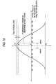
- a relationship between an offset angle of an initial magnetic pole position and a generated torque hereinafter, a thrust force of a linear motor is also shown as a torque
- Equation (1) A relationship between an offset angle of an initial magnetic pole position and a generated torque (hereinafter,
- T is a generated torque
- Tm is a maximum value of the torque
- ⁇ error is an offset angle of the initial magnetic pole position
- a prior art technique described in Japanese Patent Laid-Open No. 153576/1994 applies a voltage corresponding to an arbitrary initial magnetic pole position angle to estimate the initial magnetic pole position from information on a rotating direction and a rotational speed of a motor at that time.
- This initial magnetic pole estimating method repeats the estimation to find a correct initial magnetic pole position.
- the prior art technique involves a repetition-based trial and error method which approaches from a wide estimation error range to a narrower estimation error range of the initial magnetic pole position to estimate a true value for the initial magnetic pole position of an AC synchronous motor, and experiences the following problems:
- a correct initial magnetic pole position cannot be estimated (a magnetic pole position estimation accuracy range is within ⁇ 30°);
- the gist of an initial magnetic pole estimating apparatus for an AC synchronous motor according to the present invention lies in the following (1)-(32).
- An initial magnetic pole estimating apparatus for an AC synchronous motor equipped in an AC synchronous motor controller comprising speed control means for calculating a command torque (command current) from a command speed, current control means for driving the AC synchronous motor in accordance with the command torque (command current), and a PWM power converter, wherein the initial magnetic pole estimating apparatus is characterized by having speed deviation calculating means for subtracting the detected speed from the command speed generated by command speed pattern generating means to calculate a speed deviation, a speed gain control unit for multiplying the speed deviation by a speed gain to calculate a command torque (command current), mode section determining means for determining a mode section (a first cyclic section and a second cyclic section) from the command speed, a mode switch for switching a mode section to any of the first cyclic section and the second cyclic section in accordance with a result in the mode section determining means, data acquisition speed section determining means for determining whether the command speed is in a data acquisition speed section when the first cyclic section is selected, a first command
- An initial magnetic pole estimating apparatus for an AC synchronous motor equipped in an AC synchronous motor controller comprising PWM power converting means for converting a direct current voltage to an arbitrary alternate current voltage to drive the AC synchronous motor, three-phase current detecting means for detecting a three-phase current of the AC synchronous motor, an electric angle detecting means for detecting a relative electric angle of the AC synchronous motor, three-phase/two-phase coordinate conversion calculating means for performing a three-phase/two-phase coordinate conversion from a detected three-phase current to a detected two-phase current using the detected electric angle, detected speed calculating means for calculating a detected speed from the detected electric angle, two-phase current error calculating means for subtracting the detected two-phase current from a two-phase command current comprised of a q-axis command current and a d-axis command current to calculate a current error, a two-phase current proportion integration control unit for multiplying the current error by a two-phase current proportion integration gain to calculate a two-phase command voltage, two-phase
- An initial magnetic pole estimating apparatus for an AC synchronous motor equipped in an AC synchronous motor controller comprising PWM power converting means for converting a direct current voltage to an arbitrary alternate current voltage to drive the AC synchronous motor, three-phase current detecting means for detecting a three-phase current of the AC synchronous motor, an electric angle detecting means for detecting a relative electric angle of the AC synchronous motor, detected speed calculating means for calculating a detected speed from the detected electric angle, three-phase command current calculating means for calculating three-phase command current comprised of a A-phase command current, a B-phase command current and a C-phase command current from a command torque (command current) using the detected electric angle, three-phase current error calculating means for subtracting the detected three-phase current from a three-phase command current to calculate a current error, a three-phase current proportion integration control unit for multiplying the current error by a three-phase current proportion integration gain to calculate a three-phase command voltage, and PWM gate pulse calculating means for comparing the three-phase
- the command speed pattern generating means is capable of arbitrarily setting an acceleration/deceleration section time and a constant speed section time, arbitrarily setting a speed waveform in the acceleration/deceleration section, and arbitrarily setting an amplitude value for a command speed to generate the command speed as a trapezoidal wave, a triangular waver, a rectangular wave, a zero-speed wave, a sinusoidal wave, and the like as a two-cycle waveform.
- An initial magnetic pole estimating apparatus for an AC synchronous motor according to any one of the foregoing (1)-(4), characterized in that the speed gain control unit functions as a speed proportion control unit, a speed proportion integration control unit or a speed integration control unit in a combination of a speed proportion control unit and a speed integration control unit.
- An initial magnetic pole estimating apparatus for an AC synchronous motor according to any one of the foregoing (1)-(6), characterized in that in the dq current control means used as the current control means, the command current is inputted to the q-axis command current, and a constant value is inputted to the d-axis command current in the first cyclic section, and the command current is inputted to the d-axis command current, and a constant value is inputted to the q-axis command current in the second cyclic section.
- An initial magnetic pole estimating apparatus for an AC synchronous motor characterized in that in the three-phase current control means used as the current control means, in the first cyclic section, after a shift angle equal to zero degrees is added to the detected electric angle (without phase change), the command torque (the command current) is converted to a three-phase command current as shown in the following equations, and in the second cyclic section, after a shift angle equal to 90 degrees is added to the detected electric angle (phase change by 90 degrees), the command torque (the command current) is converted to a three-phase command current as shown in the following equations.
- Ib* I * ⁇ cos( ⁇ fb ⁇ shift ⁇ 120 degrees)
- Ic* I * ⁇ cos( ⁇ fb ⁇ shift ⁇ 240 degrees)
- I* is a command torque (command current)
- ⁇ fb is a detected electric angle (relative position).
- ⁇ shift is a shift angle (zero degrees in the first cyclic section, and 90 degrees in the second cyclic section);
- Ia* is an A-phase command current
- Ib* is a B-phase command current
- Ic* is a C-phase command current.
- An initial magnetic pole estimating apparatus for an AC synchronous motor according to any one of the foregoing (1)-(10), characterized in that the data acquisition speed section is comprised of a combination of a positive acceleration section, a negative acceleration section, a positive deceleration section, a negative deceleration section, a positive constant speed section, and a negative constant speed section.
- An initial magnetic pole estimating apparatus for an AC synchronous motor according to any one of the foregoing (1)-(11), characterized in that the data acquisition speed section determining means is acceleration section determining means when the magnetic pole estimating data is acquired in an acceleration section; constant speed section determining means when acquired in a constant speed section; acceleration/constant speed section determining means when acquired in an acceleration section and a constant speed section; deceleration/constant speed section determining means when acquired in a deceleration section and a constant speed section; acceleration/deceleration determining means when acquired in an acceleration section and a deceleration section; and an acceleration/deceleration/constant speed section determining means when acquired in an acceleration section, a deceleration section and a constant speed section.
- An initial magnetic pole estimating apparatus for an AC synchronous motor according to any one of the foregoing (1)-(12), characterized in that when the data acquisition speed section determining means is the constant speed section determining means, the magnetic pole estimating data is calculated after the arbitrary time set due to the fact that it can be set from zero to an arbitrary time (however, the arbitrary time is smaller than an end time of the constant speed section) until the end time of the constant speed section.
- An initial magnetic pole estimating apparatus for an AC synchronous motor characterized by having first memory storing means for storing the first command current data calculated in the first cyclic section in a memory, and second memory storing means for storing the second command current data calculated in the second cyclic section in a memory.
- An initial magnetic pole estimating apparatus for an AC synchronous motor according to any one of the foregoing (1)-(14), characterized by calling the command torque data (first and second command torque data) from the memory.
- An initial magnetic pole estimating apparatus for an AC synchronous motor according to any one of the foregoing (1)-(15), characterized in that the estimated initial magnetic pole position is calculated as expressed by tan ⁇ 1 (the first command current data/the second command current data), or a combination of cos ⁇ 1 and sin ⁇ 1 , or the estimated initial magnetic pole position is calculated as expressed by ⁇ (tan ⁇ 1 (the first instantaneous command current data/the second instantaneous command current data) )/k when the first and second command current data are instantaneous command currents, or calculated from a relationship between the first command current data and the second command current data.
- An initial magnetic pole estimating apparatus for an AC synchronous motor according to any one of the foregoing (1)-(16), characterized in that the first command current data and second command current data calculated by the first command current calculating means and the second command current calculating means are a maximum command current, an average command current and an instantaneous command current, wherein the maximum command current is a maximum value calculated from a command current which is in the data acquisition speed section, the average command current is an average of the command current which is in the data acquisition speed section, and the instantaneous command current is a command current which is an instantaneously calculated command current which is in the data acquisition speed section.
- An initial magnetic pole estimating apparatus for an AC synchronous motor according to any one of the foregoing (1)-(17), characterized in that in the command speed, a pause section in which the command speed has a zero command speed is provided when switching between positive and negative, and a time for the pause section can be arbitrarily set.
- An initial magnetic pole estimating apparatus for an AC synchronous motor according to any one of the foregoing (1)-(18), characterized in that in the command speed, a pause section in which the command speed is zero is provided between a first cyclic section in a first cycle and a second cyclic section in a second cycle, and a section is switched during the pause section.
- An initial magnetic pole estimating apparatus for an AC synchronous motor according to any one of the foregoing (1)-(19), characterized in that the command current, a pause section is provided when a forced phase change is performed, and the phase change is performed in the pause section.
- An initial magnetic pole estimating apparatus for an AC synchronous motor according to any one of the foregoing (1)-(20), characterized by having speed integration gain processing means for performing speed integration gain processing (clearing, holding and the like of an integration term) of the speed gain control unit, when the first cyclic section is switched to the second cyclic section, or when a forced phase change is performed, in the command current.
- An initial magnetic pole estimating apparatus for an AC synchronous motor according to any one of the foregoing (1)-(21), characterized in that an axial direction determining command speed provided for determining a direction (region) of a torque axis or a magnetic flux axis of the AC synchronous motor uses a first cyclic waveform of the command speed according to the foregoing (4).
- An initial magnetic pole estimating apparatus for an AC synchronous motor according to any one of the foregoing (1)-(22), characterized in that a user sets one or more of a speed deviation limit level, a torque limit level, a speed limit level, and a data deviation limit level in a parameter setting memory within the initial magnetic pole estimating apparatus for an AC synchronous motor.
- An initial magnetic pole estimating apparatus for an AC synchronous motor according to any one of the foregoing (1)-(24), characterized in that excessive torque determining means compares a command torque supplied from the speed control unit with the torque limit level to determine an excessive command torque for the motor.
- An initial magnetic pole estimating apparatus for an AC synchronous motor characterized by dividing 360 degrees of electric angle by a certain positive integer n, assuming that the torque axis exists in a certain direction within 360 degrees, controlling the AC synchronous motor with an axial direction determining command speed, determining an excessive speed deviation in the excessive speed deviation determining means, and estimating a direction of the torque axis from the determination result.
- An initial magnetic pole estimating apparatus for an AC synchronous motor characterized by assuming that the torque axis of the AC synchronous motor is in another direction in accordance with the result of the excessive speed deviation determination, and estimating the direction of the torque axis of the AC synchronous motor by repeating the operation of controlling the AC synchronous motor with the axial direction determining command speed, and determining the excessive speed deviation in the excessive speed deviation determining means by a predefined subroutine.
- An initial magnetic pole estimating apparatus for an AC synchronous motor characterized by estimating the direction of the torque axis of the AC synchronous motor in the axial direction determining means according to any one of the foregoing (22)-(28), and thereafter estimating an initial magnetic pole position of the AC synchronous motor in the calculation processing according to the foregoing (1), (2) or (3).
- An initial magnetic pole estimating apparatus for an AC synchronous motor according to any one of the foregoing (1)-(29), characterized in that excessive data deviation determining means compares a difference between the first command torque data and the second command torque data (data difference) with the data deviation limit level to determine an excessive data deviation.
- An initial magnetic pole estimating apparatus for an AC synchronous motor according to any one of the foregoing (1)-(30), characterized by determining an excessive data deviation in the excessive data deviation determining means, and estimating an initial magnetic pole position of the AC synchronous motor again by the calculation processing according to the foregoing (1), (2) or (3) after changing to a predefined phase, when the determination result shows “data deviation ⁇ data deviation limit level.”
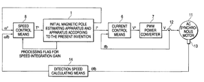
- FIG. 1 is a general block diagram of a speed control including an initial magnetic pole estimating apparatus directed by the present invention
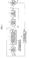
- FIG. 2 is a block diagram of a speed control based on a dq current control (vector control) including an initial magnetic pole estimation method for an AC synchronous motor according to an embodiment of the present invention
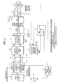
- FIG. 3 is a detailed block diagram related to the initial magnetic pole estimating method for an AC synchronous motor according to the embodiment of the present invention
- FIG. 4 is a detailed block diagram related to the initial magnetic pole estimating method for an AC synchronous motor according to the embodiment of the present invention
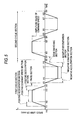
- FIG. 5 is a diagram related to a command speed pattern (trapezoidal wave) having a command speed over two cycles according to the embodiment of the present invention
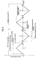
- FIG. 6 is a diagram related to a command speed pattern (triangular wave) having a command speed over two cycles according to the embodiment of the present invention
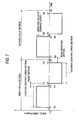
- FIG. 7 is a diagram related to a command speed pattern (rectangular wave) having a command speed over two cycles according to the embodiment of the present invention.
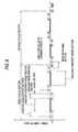
- FIG. 8 is a diagram related to a command speed pattern (zero-speed wave) having a command speed over two cycles according to the embodiment of the present invention.
- FIG. 9 is a diagram related to a dq mode switch in the detailed block diagram of the initial magnetic pole estimating method illustrated in FIG. 3;
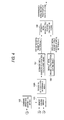
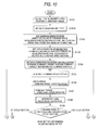
- FIG. 10 is a flow chart related to the initial magnetic pole estimating method for an AC synchronous motor according to the embodiment of the present invention.
- FIG. 11 is a flow chart related to the initial magnetic pole estimating method for an AC synchronous motor according to the embodiment of the present invention.
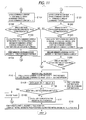
- FIG. 12 is a flow chart for determining a region of a torque axis or a magnetic flux axis according to the embodiment of the present invention.
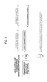
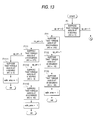
- FIG. 13 is a flow chart related to a “subroutine for determining the direction of the torque axis” at 108 in the flow chart of FIG. 12;
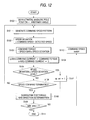
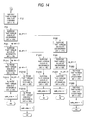
- FIG. 14 is a flow chart continued from a position (A) in the flow chart of FIG. 13;
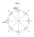
- FIG. 15 is a diagram in which 360 degrees are divided into eight for representing respective directions in accordance with the embodiment of the present invention.
- FIG. 16 is a diagram showing a relationship between an offset angle of an initial magnetic pole position and a generated torque.
- * is a suffix indicative of a command
- fb is a suffix indicative of detection
- d-q indicates a two-phase coordinate system
- a-b-c indicates a three-phase coordinate system
- Vt indicates a carrier triangular wave voltage
- Vdc indicates a direct current voltage of a PWM invertor
- Vq*, Vd* indicate command voltages for a d-axis and a q-axis in the two-phase coordinates
- Va*, Vb*, Vc* indicate command voltages in an a-phase, a b-phase and a c-phase in the three-phase coordinate system
- Va, Vb, Vc indicate output voltages of an invertor in the a-phase, b-phase and c-phase in the three-phase coordinates
- T* indicates a command torque
- I* indicates a command current
- Tm, T, Tloss indicates a maximum torque value, a generated torque (thrust force) and a torque
- Reference numeral 1 designates an initial magnetic pole estimating apparatus and method according to the present invention
- 6 a current control means
- 7 a PWM power converter
- 8 a speed control means
- 11 an AC synchronous motor (a rotary motor or a linear motor);
- 12 a three-phase alternate current detector (CT); 13 an encoder;
- 14 a detected speed calculating means; 15 a compensated initial magnetic pole position calculating means; 61 a 3/2 coordinate conversion calculating means;
- 62 a subtractor (current error calculating means); 63 a current proportional integral control unit;
- 64 a 2/3 coordinates conversion calculating means;
- 71 a PWM gate pulse generator
- 72 a triangular carrier wave
- 73 a PWM invertor
- 74 a direct current power supply
- 82 a speed gain control means; 101 a command speed pattern generating means; 102 a mode section determining means; 103 a speed integration gain processing
- FIG. 1 is a general block diagram of a speed control including an initial magnetic pole estimating apparatus directed by the present invention.
- an AC motor 11 is driven by a current control means 6 and a PWM power converter 7 in accordance with a command torque.
- the AC synchronous motor 11 is an AC rotary motor or an AC linear motor which does not have a magnetic pole sensor (pole sensor).
- a current detecting means 12 detects a current Ifb of the AC motor 11
- an electric angle detecting means (encoder) 13 detects a relative electric angle (relative position) ⁇ fb of the AC motor.
- a detected speed calculating means 14 calculates a detected speed ⁇ fb from the detected electric angle ⁇ fb detected by the electric angle detecting means 13 .
- the initial magnetic pole estimating apparatus and method 1 generate a command speed, calculates a command torque in a speed control means 8 from information on the command speed and a detected speed, and performs processing in accordance with the initial magnetic pole estimating apparatus and method of the present invention from information on the command torque to find an estimated initial magnetic pole position for an AC synchronous motor.
- FIG. 2 is a block diagram of a speed control based on a dq current control (vector control) including an initial magnetic pole method for an AC synchronous motor according to an embodiment of the present invention.
- FIGS. 3-4 are detailed block diagrams related to the initial magnetic pole estimating method for an AC synchronous motor according to the embodiment of the present invention.
- FIGS. 5-8 are diagrams related to command speed patterns having a waveform over two cycles according to the embodiment of the present invention, wherein FIG. 5 shows a command speed pattern of a trapezoidal wave; FIG. 6 shows a command speed pattern of a triangular wave; FIG. 7 shows a command speed pattern of a rectangular wave; and FIG. 8 shows a command speed pattern of a zero-speed wave.
- FIG. 5 shows a command speed pattern of a trapezoidal wave
- FIG. 6 shows a command speed pattern of a triangular wave
- FIG. 7 shows a command speed pattern of a rectangular wave
- FIG. 8 shows a command speed pattern of a zero-speed wave.
- a command speed increase/decrease pattern is arbitrary in an acceleration/deceleration section, a first-order increase/decrease function is used here for purposes of description.
- FIG. 9 is a diagram related to a mode switch in the detailed block diagrams of the initial magnetic pole estimating method illustrated in FIGS. 3-4.
- FIGS. 10-11 are flow charts related to the initial magnetic pole estimating method for an AC synchronous motor according to the embodiment of the present invention.
- Sections for the command speed pattern over two cycles illustrated in FIGS. 5-8 are defined in the following manner.
- t 10 -t 20 is a first cyclic section
- t 20 -t 30 is a second cyclic section.
- t 10 -t 11 is a zero speed start section
- t 14 -t 15 is a pause section
- t 18 -t 22 is a mode switching section
- t 24 -t 25 is a pause section
- t 28 -t 30 is a zero speed end section.
- the foregoing sections are zero speed sections (comprised of the zero speed start section, pause section, mode switching section, and zero speed end section), and these sections are also referred to as the pause section. These sections are shown in Table 2
- a trapezoidal basic waveform (set time I)—applied waveforms (set time II—set time IV, and others) are contemplated by performing time settings for the sections in accordance with applications. These are shown in Table 5.
- a command speed amplitude value of 50 is an arbitrarily set value, the unit of which is r/min (for a rotary motor) or mm/sec (for a linear motor).
- the data acquisition speed section provided for acquiring data for a magnetic pole estimation can be selected from a variety of sections shown in FIG. 6 based on the command speed patterns defined above. These sections are shown in Table 6.
- ⁇ indicates that the data acquisition speed section an be set
- X indicates that the section cannot be set
- the type of data acquired for magnetic pole estimation in the data acquisition speed section can be set from the following three:
- the first command current and second command current can be selected from a maximum command torque, an average command torque and an instantaneous command torque in setting the type of data acquired for magnetic pole estimation, and calculations for acquiring the respective data are performed in accordance with the following equations (2)-(7):
- I 1 max* MAC( I 1 *[ k ]) (2)
- I 2 max* MAC( I 2 *[ k ]) (3)
- I 1 ave* ⁇ ( I 1 *[ k ])/ k (4)
- I 2 ave* ⁇ ( I 2 *[ k ])/ k (5)
- I 1 max* and I 2 max* are a first and a second maximum command current
- I 1 ave* and I 2 ave* are a first and a second average command current
- I 1 inst*[k] and I 2 inst*[k] are a first and a second instantaneous command current
- MAX is a function for calculating a maximum value
- k is an arbitrary number of data.
- the embodiment of the present invention performs the initial magnetic pole estimating method illustrated in FIG. 3 in a speed control loop in a dq current control means for an AC synchronous motor illustrated in FIG. 2 .
- the dq current control for an AC synchronous motor comprises a configuration except for the AC synchronous motor 11 in FIG. 1 .
- the AC synchronous motor 11 is driven by a PWM power converting means 72 for converting a direct current voltage 74 into an arbitrary alternate current voltage
- a three-phase current of the AC synchronous motor is detected by a three-phase current detector 12
- a relative electric current of the AC synchronous motor is detected by an electric angle detector 13
- a three-phase/two-phase coordinate conversion is performed by a three-phase/two-phase coordinate conversion calculating means 61 from the detected three-phase current to a detected two-phase current using information on the electric angle.
- a detection speed ⁇ is calculated by a detected speed calculating means 14 using a detected electric angle ⁇ .
- the detected two-phase current is subtracted from a two-phase command current to calculate a current error in a current error calculating means 62 , the current error is multiplied by a two-phase proportional integral gain to calculate a two-phase command voltage in a two-phase current proportional integral control unit 63 , and a two-phase/three-phase coordinate conversion is performed in a two-phase/three-phase coordinate conversion calculating means 64 from the two-phase command voltage to a three-phase command voltage using the information on the electric angle.
- the three-phase command voltage is compared with a triangular carrier waver 72 to calculate PWM gate pulses in a PWM gate pulse generating means 71 , and these pulses are outputted to the PWM invertor 73 .
- a trapezoidal command speed pattern is generated in a command speed pattern generating means 101 , a detected speed is subtracted from the command speed to calculate a speed deviation in a speed deviation calculating means 81 , and the speed deviation is multiplied by a speed gain to calculate a command torque (command current) in a speed gain control unit 82 .
- a mode section determining means 102 determines a mode section for a first cyclic section and a second cyclic section from the trapezoidal command speed, and a mode section switching operation is performed in a mode switch 104 in accordance with the determination result.
- the switching is performed without fail in a mode switching section which is a zero-speed section.
- a mode switching section which is a zero-speed section.
- a speed integration gain integration term
- the mode is switched by the mode switch within t 17 -t 20 .
- the integration term of the speed integration gain is cleared at an instance the mode is switched by the mode switch.
- a command 1 torque (command current) calculated in the speed gain control unit is inputted to a q-axis command current, while zero is inputted to a d-axis command current.
- An acceleration section determining means 1102 determines whether or not a command speed is a positive acceleration section.
- a first maximum command torque (first maximum command current) is calculated from a certain command torque in the determined section, and stored in a memory by a first memory storing means 1104 .
- An acceleration section determining means 1202 determines whether or not a command speed is a positive acceleration section.
- a second maximum command torque (second maximum command current) is calculated from a certain command torque in the determined section, and stored in a memory by a second memory storing means 1204 .
- the first maximum command current data and second maximum command current data stored in the memories are called from the memories by a memory calling means 106 , and an excessive data deviation determining means 106 A determines excessive data from the called first command current data and second command current data.
- an estimated initial magnetic pole position ⁇ est is calculated in an estimated initial magnetic pole calculating means 107 of Equation (8) from information on the called first command current data and second command current data.
- the first and second command current data (I 1 data*, I 2 data*), when stored in the memories, have the same values as the called first and second command current data (I 1 data*call, I 2 data*call).
- Routine I of Memory I 1 data* ⁇ Memory ⁇ I 2 data*call;
- ⁇ est is an estimated initial magnetic pole position
- FNC is an arbitrary function
- I 1 data* is the first command current data (first command torque data).
- I 2 data* is the second command current data (second command torque data).
- a compensated initial magnetic pole calculating means 109 using Equation (9) adds the estimated initial magnetic pole position ⁇ est to a default initial magnetic pole position ⁇ 0 set by a default initial magnetic pole position setting means 108 to calculate a compensated initial magnetic pole position ⁇ comp:
- ⁇ comp is the compensated initial magnetic pole position
- ⁇ 0 is the default initial magnetic pole position (arbitrary value) in the initial settings.
- the estimated initial magnetic pole position ⁇ est ( ⁇ estmax, ⁇ estave, ⁇ estinst) is calculated by the following Equations (10)-(12):
- FIG. 12 is a flow chart for determining a region of a torque axis or a magnetic flux axis in accordance with the embodiment of the present invention.
- FIG. 13 is a flow chart related to a “subroutine for determining the direction of the torque axis” at S 108 in the flow chart of FIG. 12 .
- FIG. 14 is a flow chart continued from a position (A) in the flow chart of FIG. 13 .
- FIG. 15 is a diagram in which 360 degrees are divided into eight for representing respective directions in accordance with the embodiment of the present invention.
- a procedure for the aforementioned initial magnetic pole estimation calculating means is shown as follows, including the processing for determining the direction of the torque axis of the AC synchronous motor.
- the direction (region) of the torque axis is determined in the following manner with reference to the flow chart of FIG. 12 .
- S 100 Set a default initial magnetic pole position (currently set initial magnetic pole position) to zero. Also, set a safe_area determination flag to zero. Go to S 101 .
- S 104 Input a command torque (command current) to a q-axis command current, and input zero to a d-axis command current. Go to S 105 .
- F 1 Assume that the torque axis of the AC synchronous motor exists in a direction ( 1 ) in FIG. 15 (set ⁇ 0 to zero degrees). If O.K., go to F 11 . If N.G., go to F 12 .
- F 10 Assume that the torque axis exists in a direction ( 4 ) in FIG. 15 (set ⁇ 0 to 135 degrees). If O.K., go to F 101 . If N.G., go to F 102 .
- F 11 Assume that the torque axis exists in a direction ( 8 ) in FIG. 15 (set ⁇ 0 to 315 degrees). If O.K., go to F 111 . If N.G., go to F 112 .
- F 12 Set immediately the torque axis determining command speed to zero, and do nothing until the next shaft determining command speed. Go to F 10 .
- F 100 Assume that the torque axis exists in a direction ( 5 ) in FIG. 15 (set ⁇ 0 to 180 degrees). If O.K., go to F 1001 . If N.G., go to F 1012 .
- F 101 Assume that the torque axis exists in a direction ( 3 ) in FIG. 15 (set ⁇ 0 to 90 degrees). If O.K., go to F 1011 . If N.G., go to F 1012 .
- F 102 Set immediately the shaft determining command speed to zero, and assume that the torque axis exists in a direction ( 6 ) in FIG. 15 (set ⁇ 0 to 225 degrees) until the next shaft determining command speed. Go to F 100 when the next shaft determining command speed is supplied.
- F 111 Assume that the torque axis exists in a direction ( 7 ) in FIG. 15 (set ⁇ 0 to 270 degrees). If O.K., go to F 1111 . If N.G., go to F 1112 .
- F 112 Set immediately the shaft determining command speed to zero, and assume that the torque axis exists in a direction ( 2 ) in FIG. 15 (set ⁇ 0 to 45 degrees) until the next shaft determining command speed. Go to F 110 when the next shaft determining command speed is supplied.
- F 1002 Set immediately the shaft determining command speed to zero, and assume that the torque axis exists in a direction ( 7 ) in FIG. 15 (set ⁇ 0 to 270 degrees) until the next shaft determining command speed. Go to F 1000 when the next shaft determining command speed is supplied.
- F 1011 Assume that the torque axis exists in a direction ( 2 ) in FIG. 15 (set ⁇ 0 to 45 degrees). If O.K., go to F 10111 . If N.G., go to F 10112 .
- F 1012 Set immediately the shaft determining command speed to zero, and assume that the torque axis exists in a direction ( 5 ) in FIG. 15 (set ⁇ 0 to 180 degrees) until the next shaft determining command speed. Go to F 1010 when the next shaft determining command speed is supplied.
- F 1112 Set immediately the shaft determining command speed to zero, and assume that the torque axis exists in a direction ( 1 ) in FIG. 15 (set ⁇ 0 to 0 degrees) until the next shaft determining command speed. Go to F 1110 when the next shaft determining command speed is supplied.
- F 10112 Set immediately the shaft determining command speed to zero, and assume that the torque axis exists in a direction ( 4 ) in FIG. 15 (set ⁇ 0 to 135 degrees) until the next shaft determining command speed. Go to F 10110 when the next shaft determining command speed is supplied.
- Step 1 Set the default initial magnetic pole position ⁇ 0 as an arbitrary angle (E 101 )
- Step 1A Set a data deviation limit level (E 101 A)
- Step 2 Set a command speed pattern (an amplitude value of a command speed, an acceleration section time, a constant speed section time, a pause section time, a mode switching section time) in the command speed pattern generating means, and generate an optimal command speed pattern (trapezoidal wave, triangular wave, rectangular wave, zero-speed wave, sinusoidal wave) for an application field to which it is applied (E 102 , E 105 ).
- a command speed pattern an amplitude value of a command speed, an acceleration section time, a constant speed section time, a pause section time, a mode switching section time
- an optimal command speed pattern trapezoidal wave, triangular wave, rectangular wave, zero-speed wave, sinusoidal wave
- Step 3 Set a data acquisition speed section (see Table 2) and data acquired for magnetic pole estimation in the data acquisition speed section (maximum command current, average command current, instantaneous command current) based on the command speed pattern generated at E 102 (E 103 , E 104 )
- Step 4 Subtract a detected speed from the command speed to calculate a speed deviation (E 106 ).
- Step 5 Multiply the speed deviation by a speed gain (any of a speed proportion gain, a speed proportion integration gain, and a speed integration gain) to calculate a command torque (command current) (E 107 ).
- a speed gain any of a speed proportion gain, a speed proportion integration gain, and a speed integration gain
- Step 6 Determine a mode section (the first cyclic section and second cyclic section) from the command speed in the mode section determining means, and perform a switching operation from the first cyclic section to the second cyclic section in accordance with the result in the mode switch (E 109 ).
- Step 7 Perform operations from step 8A to step 8C (E 1101 -E 1104 ) in the first cyclic period found at E 109 , or perform the operations from step 9A to step 9C (E 1201 -E 1205 ) in the second cyclic section found at E 107 .
- Step 8A Input the command torque (command current) calculated at step 5 to the q-axis command current, and input zero to the d-axis command current (E 1101 ).
- Step 8B Determine whether the command speed is a data acquisition speed section, and calculate first command current data (first command torque data) from the command torque in the determined section (E 1102 , E 1103 ).
- Step 8C Store the first command current data in a memory by the first memory storing means (E 1104 ).
- Step 9A Input zero to the q-axis command current, and input the command torque (command current) calculated at step 5 to the d-axis command current (E 1201 ).
- Step 9B Determine whether the command speed is a data acquisition speed section, and calculate second command current data (second command torque data) from the command torque in the determined section (E 1202 , E 1203 )
- Step 9C Store the second command current data in a memory by the second memory storing means (E 1204 ).
- Step 10 Call the first and second command current data from the memories after the end of the second cyclic section of the command speed (E 1205 ) (E 110 ).
- Step 11 Calculate the difference between the first command current data and second command current data called at E 110 as a data deviation (E 110 A).
- Step 12 Compare the data deviation with a data deviation limit level, and when the result shows “data deviation ⁇ data deviation limit level,” calculate again from E 105 after a change to a predefined phase (E 110 B, E 110 C).
- Step 12A Compare the data deviation with a data deviation limit level, and when the result shows “data deviation ⁇ data deviation limit level,” calculate an estimated initial magnetic pole position in the estimated initial magnetic pole calculating means using Equation (8), using the first command current data and second command current data called at E 110 (E 111 ).
- Step 13 Add the estimated initial magnetic pole position ⁇ est to the default initial magnetic pole position ⁇ 0 to calculate a compensated initial magnetic pole position ⁇ comp in the compensated initial magnetic pole calculating means using Equation (9) (E 112 ).
- a correct initial magnetic pole position estimation can be accomplished in a short estimation time; 2) a maximum torque can be generated while minimizing a torque loss; and 3) a range in which the motor moves can be minimized.
Landscapes
- Engineering & Computer Science (AREA)
- Power Engineering (AREA)
- Control Of Ac Motors In General (AREA)
- Control Of Motors That Do Not Use Commutators (AREA)
Applications Claiming Priority (5)
| Application Number | Priority Date | Filing Date | Title |
|---|---|---|---|
| JP26455699 | 1999-09-17 | ||
| JP11/264556 | 1999-09-17 | ||
| JP2000221364A JP4239372B2 (ja) | 1999-09-17 | 2000-07-21 | Ac同期モータの初期磁極推定装置 |
| JP2000/221364 | 2000-07-21 | ||
| PCT/JP2000/006270 WO2001022568A1 (fr) | 1999-09-17 | 2000-09-13 | Dispositif d'estimation du pole magnetique initial pour moteur synchrone ca |
Publications (1)
| Publication Number | Publication Date |
|---|---|
| US6677724B1 true US6677724B1 (en) | 2004-01-13 |
Family
ID=26546564
Family Applications (1)
| Application Number | Title | Priority Date | Filing Date |
|---|---|---|---|
| US10/088,355 Expired - Lifetime US6677724B1 (en) | 1999-09-17 | 2000-09-13 | Initial magnetic pole estimating device for AC synchronous motor |
Country Status (7)
| Country | Link |
|---|---|
| US (1) | US6677724B1 (fr) |
| EP (1) | EP1213828A4 (fr) |
| JP (1) | JP4239372B2 (fr) |
| KR (1) | KR100722584B1 (fr) |
| CN (1) | CN1258868C (fr) |
| TW (1) | TW486856B (fr) |
| WO (1) | WO2001022568A1 (fr) |
Cited By (20)
| Publication number | Priority date | Publication date | Assignee | Title |
|---|---|---|---|---|
| US20020117990A1 (en) * | 2001-02-27 | 2002-08-29 | Hitachi Ltd. | Motor control apparatus and electric vehicle using same |
| US20040061461A1 (en) * | 2002-10-01 | 2004-04-01 | Honda Giken Kogyo Kabushiki Kaisha | Apparatus for controlling permanent-magnet rotary machine |
| US20050073273A1 (en) * | 2003-10-06 | 2005-04-07 | Wavecrest Laboratories, Llc | Fault-tolerant electric motor control system |
| US20050093498A1 (en) * | 2003-10-30 | 2005-05-05 | Luk Lamellen Und Kupplungsbau Beteiligungs Kg | EC motor and method for operating same |
| US20070035269A1 (en) * | 2005-08-11 | 2007-02-15 | Kazuaki Tobari | Vector controller for permanent magnet synchronous motor |
| US20070216342A1 (en) * | 2006-03-15 | 2007-09-20 | Kazuaki Tobari | Vector Control Apparatus for Permanent Magnet Motor |
| US20080309268A1 (en) * | 2005-09-26 | 2008-12-18 | Kabushiki Kaisha Yaskawa Denki | Initial Pole Position Estimating Apparatus and Method for Ac Synchronous Motor |
| US20090079370A1 (en) * | 2005-02-24 | 2009-03-26 | Mitsubishi Heavy Industries, Ltd. | Ipm motor system and control method thereof |
| US20090267547A1 (en) * | 2007-03-28 | 2009-10-29 | Kabushiki Kaisha Yaskawa Denki | Motor control device and magnetic pole position estimation precision confirming method |
| US20100148707A1 (en) * | 2008-12-12 | 2010-06-17 | Hitachi Industrial Equipment System Co., Ltd. | Speed controller of magnetic motor |
| US20100320948A1 (en) * | 2009-06-18 | 2010-12-23 | Semyon Royak | Method and Apparatus for Increased Current Stability in a PWM Drive |
| US20120227514A1 (en) * | 2011-03-09 | 2012-09-13 | Jtekt Corporation | Rotation angle detection device and torque detection device |
| US20140028226A1 (en) * | 2012-07-26 | 2014-01-30 | Milwaukee Electric Tool Corporation | Brushless direct-current motor and control for power tool |
| US20140176028A1 (en) * | 2011-08-18 | 2014-06-26 | Kazuaki Tobari | Motor control device and work machine using the same |
| US20160006374A1 (en) * | 2014-07-03 | 2016-01-07 | Hyundai Motor Company | System and method for cold start of vehicle |
| CN107645255A (zh) * | 2016-07-20 | 2018-01-30 | 半导体元件工业有限责任公司 | 三相电机的转子位置感测系统以及相关方法 |
| US20180069495A1 (en) * | 2016-07-20 | 2018-03-08 | Semiconductor Components Industries, Llc | Rotor position sensing system for three phase motors and related methods |
| US10205411B2 (en) | 2015-07-01 | 2019-02-12 | Schneider Toshiba Inverter Europe Sas | Control method for starting a synchronous electric motor |
| CN109562909A (zh) * | 2016-08-31 | 2019-04-02 | 蒂森克虏伯电梯股份公司 | 用于操作电梯系统的方法 |
| CN113507254A (zh) * | 2020-03-24 | 2021-10-15 | 株式会社安川电机 | 电机控制装置、电梯驱动系统和电机控制方法 |
Families Citing this family (15)
| Publication number | Priority date | Publication date | Assignee | Title |
|---|---|---|---|---|
| JP3888082B2 (ja) | 2001-06-08 | 2007-02-28 | 株式会社豊田自動織機 | モータ装置およびその制御方法 |
| JP4766362B2 (ja) * | 2001-09-17 | 2011-09-07 | 株式会社安川電機 | Ac同期モータの初期磁極推定装置 |
| JP4766361B2 (ja) * | 2001-09-17 | 2011-09-07 | 株式会社安川電機 | Ac同期モータの初期磁極推定装置 |
| JP4848609B2 (ja) * | 2001-09-26 | 2011-12-28 | 株式会社安川電機 | Ac同期モータの初期磁極推定装置 |
| AU2003290693A1 (en) * | 2003-11-10 | 2005-06-06 | International Rectifier Corporation | Efficiency optimization control for permanent magnet motor drive |
| KR101325398B1 (ko) * | 2007-03-28 | 2013-11-04 | 엘지전자 주식회사 | 전동 압축기 및 그를 포함한 공기 조화 장치 |
| KR101013886B1 (ko) * | 2008-03-03 | 2011-02-14 | 경상대학교산학협력단 | 에이씨 영구자석동기모터의 초기자극위치추정 방법 및 장치 |
| JP4458174B2 (ja) * | 2008-03-21 | 2010-04-28 | 株式会社デンソー | 回転機の制御装置、及び回転機の制御システム |
| US8853979B2 (en) * | 2011-02-28 | 2014-10-07 | Deere & Company | Method and system for calibrating rotor position offset of an electric motor |
| JP6377506B2 (ja) * | 2014-01-27 | 2018-08-22 | ヤマハ発動機株式会社 | モータ制御装置および同装置における補正データ作成方法 |
| CN106100487B (zh) * | 2016-07-08 | 2019-06-21 | 深圳市百盛传动有限公司 | 一种直线电机的初始相位角检测方法 |
| CN107979319B (zh) * | 2017-12-26 | 2019-10-25 | 浙江水利水电学院 | 一种表贴式三相永磁同步电机转子磁极初始位置定位方法 |
| JP6966344B2 (ja) * | 2018-02-01 | 2021-11-17 | 株式会社日立産機システム | 磁極位置推定方法及び制御装置 |
| US11303239B2 (en) | 2018-10-12 | 2022-04-12 | Fanuc Corporation | Magnetic pole initial position detection device using direct-current excitation method and magnetic pole position detection device |
| CN113328670B (zh) * | 2021-05-11 | 2023-06-09 | 江苏交科能源科技发展有限公司 | 一种永磁电机旋转变压器零位调整方法 |
Citations (6)
| Publication number | Priority date | Publication date | Assignee | Title |
|---|---|---|---|---|
| JPH06153576A (ja) | 1992-10-30 | 1994-05-31 | Sharp Corp | Acサーボモータの磁極位置検出装置 |
| US5652491A (en) * | 1995-03-28 | 1997-07-29 | Mitsubishi Denki Kabushiki Kaisha | Position controller for an electric motor |
| JPH1198885A (ja) | 1997-09-24 | 1999-04-09 | Fujitsu General Ltd | ブラシレスモータの制御方法 |
| US6198240B1 (en) * | 1995-10-06 | 2001-03-06 | Hitachi, Ltd. | Motor controller |
| US6344725B2 (en) * | 1999-08-20 | 2002-02-05 | Mitsubishi Denki Kabushiki Kaisha | Method and apparatus for controlling a synchronous motor |
| US6518718B2 (en) * | 2000-03-24 | 2003-02-11 | Central Japan Railway Company | Speed electromotive force phase control system adapted to low speed |
Family Cites Families (5)
| Publication number | Priority date | Publication date | Assignee | Title |
|---|---|---|---|---|
| JPS6387194A (ja) * | 1986-09-29 | 1988-04-18 | Nissan Motor Co Ltd | 同期モ−タの制御装置 |
| JPH042556A (ja) * | 1990-04-18 | 1992-01-07 | Aisin Seiki Co Ltd | 車輪制動制御装置 |
| JP2895355B2 (ja) * | 1993-06-22 | 1999-05-24 | 株式会社三協精機製作所 | ブラシレスモータの駆動回路 |
| JP3242223B2 (ja) * | 1993-08-02 | 2001-12-25 | オークマ株式会社 | 電動機の制御装置 |
| JPH08107694A (ja) * | 1994-10-05 | 1996-04-23 | Toshiba Corp | 同期電動機の制御装置 |
-
2000
- 2000-07-21 JP JP2000221364A patent/JP4239372B2/ja not_active Expired - Fee Related
- 2000-09-13 EP EP00960989A patent/EP1213828A4/fr not_active Withdrawn
- 2000-09-13 US US10/088,355 patent/US6677724B1/en not_active Expired - Lifetime
- 2000-09-13 WO PCT/JP2000/006270 patent/WO2001022568A1/fr active Application Filing
- 2000-09-13 KR KR1020027003520A patent/KR100722584B1/ko not_active IP Right Cessation
- 2000-09-13 CN CNB008130221A patent/CN1258868C/zh not_active Expired - Fee Related
- 2000-09-14 TW TW089118857A patent/TW486856B/zh not_active IP Right Cessation
Patent Citations (6)
| Publication number | Priority date | Publication date | Assignee | Title |
|---|---|---|---|---|
| JPH06153576A (ja) | 1992-10-30 | 1994-05-31 | Sharp Corp | Acサーボモータの磁極位置検出装置 |
| US5652491A (en) * | 1995-03-28 | 1997-07-29 | Mitsubishi Denki Kabushiki Kaisha | Position controller for an electric motor |
| US6198240B1 (en) * | 1995-10-06 | 2001-03-06 | Hitachi, Ltd. | Motor controller |
| JPH1198885A (ja) | 1997-09-24 | 1999-04-09 | Fujitsu General Ltd | ブラシレスモータの制御方法 |
| US6344725B2 (en) * | 1999-08-20 | 2002-02-05 | Mitsubishi Denki Kabushiki Kaisha | Method and apparatus for controlling a synchronous motor |
| US6518718B2 (en) * | 2000-03-24 | 2003-02-11 | Central Japan Railway Company | Speed electromotive force phase control system adapted to low speed |
Cited By (40)
| Publication number | Priority date | Publication date | Assignee | Title |
|---|---|---|---|---|
| US6914408B2 (en) * | 2001-02-27 | 2005-07-05 | Hitachi, Ltd. | Motor control apparatus and electric vehicle using same |
| US20020117990A1 (en) * | 2001-02-27 | 2002-08-29 | Hitachi Ltd. | Motor control apparatus and electric vehicle using same |
| US20040061461A1 (en) * | 2002-10-01 | 2004-04-01 | Honda Giken Kogyo Kabushiki Kaisha | Apparatus for controlling permanent-magnet rotary machine |
| US6984957B2 (en) * | 2002-10-01 | 2006-01-10 | Honda Giken Kogyo Kabushiki Kaisha | Apparatus for controlling permanent-magnet rotary machine |
| US20050073273A1 (en) * | 2003-10-06 | 2005-04-07 | Wavecrest Laboratories, Llc | Fault-tolerant electric motor control system |
| US6949908B2 (en) * | 2003-10-06 | 2005-09-27 | Wavecrest Laboratories, Llc | Fault-tolerant electric motor control system |
| US7279859B2 (en) * | 2003-10-30 | 2007-10-09 | Luk Lamellen Und Kupplungsbau Beteiligungs Kg | EC motor and method for operating same |
| US20050093498A1 (en) * | 2003-10-30 | 2005-05-05 | Luk Lamellen Und Kupplungsbau Beteiligungs Kg | EC motor and method for operating same |
| US7733044B2 (en) * | 2005-02-24 | 2010-06-08 | Mitsubishi Heavy Industries, Ltd. | IPM motor system and control method thereof |
| US20090079370A1 (en) * | 2005-02-24 | 2009-03-26 | Mitsubishi Heavy Industries, Ltd. | Ipm motor system and control method thereof |
| US7528568B2 (en) * | 2005-08-11 | 2009-05-05 | Hitachi, Ltd. | Vector controller for permanent magnet synchronous motor |
| US20070035269A1 (en) * | 2005-08-11 | 2007-02-15 | Kazuaki Tobari | Vector controller for permanent magnet synchronous motor |
| US7872438B2 (en) * | 2005-09-26 | 2011-01-18 | Kabushiki Kaisha Yaskawa Denki | Initial pole position estimating apparatus and method for AC synchronous motor |
| US20080309268A1 (en) * | 2005-09-26 | 2008-12-18 | Kabushiki Kaisha Yaskawa Denki | Initial Pole Position Estimating Apparatus and Method for Ac Synchronous Motor |
| US7560896B2 (en) * | 2006-03-15 | 2009-07-14 | Hitachi, Ltd. | Vector control apparatus for permanent magnet motor |
| US20070216342A1 (en) * | 2006-03-15 | 2007-09-20 | Kazuaki Tobari | Vector Control Apparatus for Permanent Magnet Motor |
| US20090267547A1 (en) * | 2007-03-28 | 2009-10-29 | Kabushiki Kaisha Yaskawa Denki | Motor control device and magnetic pole position estimation precision confirming method |
| US8049446B2 (en) * | 2007-03-28 | 2011-11-01 | Kabushiki Kaisha Yaskawa Denki | Motor control device and magnetic pole position estimation precision confirming method |
| US8344671B2 (en) * | 2008-12-12 | 2013-01-01 | Hitachi Industrial Equipment Systems Co., Ltd. | Speed controller of magnetic motor |
| US20100148707A1 (en) * | 2008-12-12 | 2010-06-17 | Hitachi Industrial Equipment System Co., Ltd. | Speed controller of magnetic motor |
| US20100320948A1 (en) * | 2009-06-18 | 2010-12-23 | Semyon Royak | Method and Apparatus for Increased Current Stability in a PWM Drive |
| US8330405B2 (en) * | 2009-06-18 | 2012-12-11 | Rockwell Automation Technologies, Inc. | Method and apparatus for increased current stability in a PWM drive |
| US20120227514A1 (en) * | 2011-03-09 | 2012-09-13 | Jtekt Corporation | Rotation angle detection device and torque detection device |
| US8607648B2 (en) * | 2011-03-09 | 2013-12-17 | Jtekt Corporation | Rotation angle detection device and torque detection device |
| US20140176028A1 (en) * | 2011-08-18 | 2014-06-26 | Kazuaki Tobari | Motor control device and work machine using the same |
| US9698716B2 (en) * | 2011-08-18 | 2017-07-04 | Hitachi Construction Machinery Co., Ltd. | Motor control device and work machine using the same |
| US9647585B2 (en) * | 2012-07-26 | 2017-05-09 | Milwaukee Electric Tool Corporation | Brushless direct-current motor and control for power tool |
| US20140028226A1 (en) * | 2012-07-26 | 2014-01-30 | Milwaukee Electric Tool Corporation | Brushless direct-current motor and control for power tool |
| US9197146B2 (en) * | 2012-07-26 | 2015-11-24 | Milwaukee Electric Tool Corporation | Brushless direct-current motor and control for power tool |
| US20160049890A1 (en) * | 2012-07-26 | 2016-02-18 | Milwaukee Electric Tool Corporation | Brushless direct-current motor and control for power tool |
| US20160006374A1 (en) * | 2014-07-03 | 2016-01-07 | Hyundai Motor Company | System and method for cold start of vehicle |
| US9337753B2 (en) * | 2014-07-03 | 2016-05-10 | Hyundai Motor Company | System and method for cold start of vehicle |
| US10205411B2 (en) | 2015-07-01 | 2019-02-12 | Schneider Toshiba Inverter Europe Sas | Control method for starting a synchronous electric motor |
| CN107645255A (zh) * | 2016-07-20 | 2018-01-30 | 半导体元件工业有限责任公司 | 三相电机的转子位置感测系统以及相关方法 |
| US20180069495A1 (en) * | 2016-07-20 | 2018-03-08 | Semiconductor Components Industries, Llc | Rotor position sensing system for three phase motors and related methods |
| US20180083558A1 (en) * | 2016-07-20 | 2018-03-22 | Semiconductor Components Industries, Llc | Rotor position sensing system for three phase motors and related methods |
| CN109562909A (zh) * | 2016-08-31 | 2019-04-02 | 蒂森克虏伯电梯股份公司 | 用于操作电梯系统的方法 |
| CN113507254A (zh) * | 2020-03-24 | 2021-10-15 | 株式会社安川电机 | 电机控制装置、电梯驱动系统和电机控制方法 |
| US11489467B2 (en) * | 2020-03-24 | 2022-11-01 | Kabushiki Kaisha Yaskawa Denki | Motor control apparatus |
| CN113507254B (zh) * | 2020-03-24 | 2024-04-30 | 株式会社安川电机 | 电机控制装置、电梯驱动系统和电机控制方法 |
Also Published As
| Publication number | Publication date |
|---|---|
| CN1375124A (zh) | 2002-10-16 |
| TW486856B (en) | 2002-05-11 |
| EP1213828A1 (fr) | 2002-06-12 |
| JP2001157482A (ja) | 2001-06-08 |
| EP1213828A4 (fr) | 2007-06-27 |
| KR100722584B1 (ko) | 2007-05-28 |
| JP4239372B2 (ja) | 2009-03-18 |
| KR20020047169A (ko) | 2002-06-21 |
| WO2001022568A1 (fr) | 2001-03-29 |
| CN1258868C (zh) | 2006-06-07 |
Similar Documents
| Publication | Publication Date | Title |
|---|---|---|
| US6677724B1 (en) | Initial magnetic pole estimating device for AC synchronous motor | |
| US6344725B2 (en) | Method and apparatus for controlling a synchronous motor | |
| JP3586230B2 (ja) | 同期リラクタンスモータの速度制御装置及びその方法 | |
| US6771039B2 (en) | Motor control apparatus and method | |
| EP1107448B1 (fr) | Dispositif de commande d'un moteur | |
| KR100455630B1 (ko) | 영구자석형 동기전동기의 센서리스 제어방법 및 장치 | |
| US6462491B1 (en) | Position sensorless motor control apparatus | |
| JP4519864B2 (ja) | 交流回転機の電気的定数測定方法およびこの測定方法の実施に使用する交流回転機の制御装置 | |
| US9093936B2 (en) | Control apparatus for AC motor | |
| EP2075904A1 (fr) | Appareil de commande sans capteur de machine synchrone | |
| US20170264227A1 (en) | Inverter control device and motor drive system | |
| US10637381B2 (en) | Inverter control device and drive system | |
| EP2120324A1 (fr) | Dispositif de commande sans capteur de moteur synchrone | |
| JP6536473B2 (ja) | 回転電機の制御装置 | |
| JP3185604B2 (ja) | 誘導機の制御装置 | |
| JPH1127996A (ja) | Acモータ用電流ベクトル制御方法およびacモータ駆動装置 | |
| JP3797508B2 (ja) | 永久磁石型同期電動機のセンサレス速度制御方法及びその脱調検出方法 | |
| JP4766362B2 (ja) | Ac同期モータの初期磁極推定装置 | |
| US11837982B2 (en) | Rotary machine control device | |
| JP4766361B2 (ja) | Ac同期モータの初期磁極推定装置 | |
| JP4735287B2 (ja) | 同期モータの制御装置およびこの同期モータの制御装置を用いた制御方法 | |
| CN108476009B (zh) | 永磁体式同步电动机的控制系统及永磁体式同步电动机的控制方法 | |
| JP4023280B2 (ja) | モータ制御装置 | |
| JP2007082380A (ja) | 同期モータ制御装置 | |
| JP4848609B2 (ja) | Ac同期モータの初期磁極推定装置 |
Legal Events
| Date | Code | Title | Description |
|---|---|---|---|
| AS | Assignment |
Owner name: KABUSHIKI KAISHA YASKAWA DENKI, JAPAN Free format text: ASSIGNMENT OF ASSIGNORS INTEREST;ASSIGNORS:TAE-WOONG, KIM;WATANABE, JUNICHI;REEL/FRAME:012936/0839 Effective date: 20020304 |
|
| FEPP | Fee payment procedure |
Free format text: PAYOR NUMBER ASSIGNED (ORIGINAL EVENT CODE: ASPN); ENTITY STATUS OF PATENT OWNER: LARGE ENTITY |
|
| STCF | Information on status: patent grant |
Free format text: PATENTED CASE |
|
| FPAY | Fee payment |
Year of fee payment: 4 |
|
| FPAY | Fee payment |
Year of fee payment: 8 |
|
| FPAY | Fee payment |
Year of fee payment: 12 |