US6648168B2 - Insulated container - Google Patents
Insulated container Download PDFInfo
- Publication number
- US6648168B2 US6648168B2 US10/362,424 US36242403A US6648168B2 US 6648168 B2 US6648168 B2 US 6648168B2 US 36242403 A US36242403 A US 36242403A US 6648168 B2 US6648168 B2 US 6648168B2
- Authority
- US
- United States
- Prior art keywords
- container
- prevention film
- radiation prevention
- thermally insulated
- section
- Prior art date
- Legal status (The legal status is an assumption and is not a legal conclusion. Google has not performed a legal analysis and makes no representation as to the accuracy of the status listed.)
- Expired - Lifetime
Links
Images


Classifications
-
- B—PERFORMING OPERATIONS; TRANSPORTING
- B65—CONVEYING; PACKING; STORING; HANDLING THIN OR FILAMENTARY MATERIAL
- B65D—CONTAINERS FOR STORAGE OR TRANSPORT OF ARTICLES OR MATERIALS, e.g. BAGS, BARRELS, BOTTLES, BOXES, CANS, CARTONS, CRATES, DRUMS, JARS, TANKS, HOPPERS, FORWARDING CONTAINERS; ACCESSORIES, CLOSURES, OR FITTINGS THEREFOR; PACKAGING ELEMENTS; PACKAGES
- B65D81/00—Containers, packaging elements, or packages, for contents presenting particular transport or storage problems, or adapted to be used for non-packaging purposes after removal of contents
- B65D81/38—Containers, packaging elements, or packages, for contents presenting particular transport or storage problems, or adapted to be used for non-packaging purposes after removal of contents with thermal insulation
-
- A—HUMAN NECESSITIES
- A47—FURNITURE; DOMESTIC ARTICLES OR APPLIANCES; COFFEE MILLS; SPICE MILLS; SUCTION CLEANERS IN GENERAL
- A47J—KITCHEN EQUIPMENT; COFFEE MILLS; SPICE MILLS; APPARATUS FOR MAKING BEVERAGES
- A47J41/00—Thermally-insulated vessels, e.g. flasks, jugs, jars
- A47J41/02—Vacuum-jacket vessels, e.g. vacuum bottles
-
- A—HUMAN NECESSITIES
- A47—FURNITURE; DOMESTIC ARTICLES OR APPLIANCES; COFFEE MILLS; SPICE MILLS; SUCTION CLEANERS IN GENERAL
- A47J—KITCHEN EQUIPMENT; COFFEE MILLS; SPICE MILLS; APPARATUS FOR MAKING BEVERAGES
- A47J41/00—Thermally-insulated vessels, e.g. flasks, jugs, jars
- A47J41/0055—Constructional details of the elements forming the thermal insulation
- A47J41/0072—Double walled vessels comprising a single insulating layer between inner and outer walls
- A47J41/0077—Double walled vessels comprising a single insulating layer between inner and outer walls made of two vessels inserted in each other
Definitions
- the present invention relates to a thermally insulated container having a double-walled structure in which an inner container and an outer container are integrally joined leaving a space therebetween, and in particular, the present invention relates to a thermally insulated container in which a radiation prevention film is formed on at least one of the outer surface of the inner container or the inner surface of the outer container.
- thermally insulated metal containers having inner and outer containers made from metals such as stainless steel have been widely used in place of conventionally used glass vacuum flasks (hereinafter, referred to as “thermally insulated containers”). Because thermally insulated metal containers are superior from the point of view of strength, they are suitable for portable use.
- Thermally insulated containers made from metal are made by arranging an inner container and an outer container, which are made of a metal such as stainless steel, leaving a space section in between and joining the opening sections thereof to form an integrated double walled container, and the space section is used to form a thermally insulating layer.
- thermally insulated metal vacuum flasks in which the space section is evacuated to form a thermally insulating vacuum layer are used generally as thermally insulated containers whose temperature maintaining performance is excellent.
- thermally insulated metal vacuum container since the inner and outer containers are metal, which is not transparent, it is not possible to check the quantity of the contents and the like from the outside, and in order to do this, it is necessary to remove the lid or the stopper, and check the inside of the container through the opening.
- thermally insulated glass containers in order to prevent thermal radiation and to increase the temperature maintaining properties, it is common for a silver-plating film to be formed by means of a silver mirror reaction on the thermally insulating layer side of the inner or outer container. In this case, it is impossible to check the contents of the container from the outside. Therefore, in the same way as for the above-mentioned thermally insulated metal containers, there is a problem that maintenance of the temperature of the contents of the container is insufficient.
- a thermally insulating layer is formed in which a gas having a thermal conductivity lower than air (hereinafter, referred to as low thermal conductivity gas), such as krypton, xenon, and argon, is enclosed within the space section.
- a gas having a thermal conductivity lower than air hereinafter, referred to as low thermal conductivity gas
- a radiation prevention film through which visible light can pass and which absorbs or reflects infrared radiation is provided on the surface of the thermally insulating layer side of the inner or outer container.
- the radiation prevention film is formed by adhering a metal oxide, a metal nitride, or fine particles of metal on a film substrate in a single layer or a multilayer by means of the vapor deposition, sputtering, ion plating, or the like.
- the radiation prevention film used in this thermally insulated container has a high rigidity, it is difficult to form curved surfaces.
- the present invention has an object of providing a thermally insulated container with which it is possible to visually inspect the contents, or the like, contained within the container, which has superior temperature maintaining performance, and which can be given an improved radiation prevention function by providing a radiation preventing performance on parts of the container which have curved surfaces as well as parts of the container which have flat surfaces.
- the radiation prevention film has a radiation prevention film omission section having an area which is 30% or less of the container surface on which the radiation prevention film is formed.
- the transparent material may be glass.
- the transparent material may be synthetic resin.
- the thermally insulating layer may be a vacuum insulation layer.
- the thermally insulating layer may enclose a low thermal conductivity gas.
- the radiation prevention film omission section may be formed in a slit shape in the axial direction of the container.
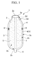
- FIG. 1 is a perspective view showing an example of the thermally insulated container of the present invention.
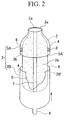
- FIG. 2 is an explanatory diagram for explaining the manufacturing method of the thermally insulated container shown in FIG. 1 .
- FIG. 3 is a graph showing the relationship between the surface area of the radiation prevention film omission section and the temperature maintaining performance of the thermally insulated container.
- FIG. 1 shows a thermally insulated vacuum container made from glass as an example of the thermally insulated container of the present invention.
- the thermally insulated container 1 shown here comprises a glass inner container 2 and a glass outer container 3 .
- These inner and outer containers 2 and 3 are formed having cylindrical shaped body sections 2 c and 3 c , and neck sections 2 d and 3 d having diameters smaller than those of the body sections 2 c and 3 c formed in the upper sections of the body sections 2 c and 3 c.
- the inner container 2 and the outer container 3 are arranged leaving a space section 4 therebetween, and the rim sections 2 a and 3 a of each opening are integrally joined, and thereby a double-walled container is formed.
- the space section 4 is vacuum evacuated to form a thermally insulating vacuum layer V.
- a radiation prevention film 5 is formed on at least one of the surfaces on the space section 4 (thermally insulating vacuum layer V) side of the inner container 2 and the outer container 3 , in other words, the outer surface 2 b of the inner container or the inner surface 3 b of the outer container.
- the radiation prevention film 5 is only formed on the outer surface 2 b of the inner container, and a radiation prevention film 5 is not formed on the inner surface 3 b of the outer container.
- This radiation prevention film 5 may be formed only on the inner surface 3 b of the outer container, or it may be formed on both of the outer surface 2 b of the inner container and the inner surface 3 b of the outer container.
- a tip tube 6 for vacuum evacuation or for gas substitution is provided at the bottom of the outer container 3 .
- the radiation prevention film 5 metal films comprising gold, silver, copper, nickel, aluminum or the like can be used.
- the radiation prevention film 5 is preferably formed by means of a chemical plating method (such as silver mirror reaction), a vapor deposition method, a sputtering method, an ion plating method, a sol-gel method, a spray coating method, a dip coat method, or the like.
- a metal foil comprising aluminum or the like is also suitable.
- the thickness of the radiation prevention film 5 is 500 ⁇ or greater (50 nm or greater), a superior radiation prevention function can be obtained, and in particular, when the thickness of the radiation prevention film 5 is 1000 ⁇ or greater (100 nm or greater), an even more superior radiation prevention action can be obtained.
- the radiation prevention film 5 has a radiation prevention film omission section 7 from which a portion of the radiation prevention film 5 has been omitted.
- the radiation prevention film omission section 7 is formed in a slit shape in the axial direction of the inner container 2 , and thereby, it is possible to check from the outside the contents housed within the inner container 2 .
- the radiation prevention film omission section 7 is formed to have a width that is approximately fixed from the rim section 2 a of the opening of the inner container 2 to the bottom of the inner container 2 .
- the radiation prevention film omission section 7 is formed so as to have surface area which is 30% or less of the surface of the container on which the radiation prevention film 5 is formed.
- the surface area of the radiation prevention film omission section 7 is set so as to be 30% or less than the surface area of the outer surface 2 b of the inner container.
- the area of the radiation prevention film omission section 7 is set so as to exceed 30% of the surface area of the outer surface 2 b of the inner container, the radiation prevention effect is degraded and the temperature maintaining properties are degraded.
- a lower limit for the surface area of the radiation prevention film omission section need not be set, and as long as it is formed so that it is possible to check from the outside the contents housed within the inner container 2 .
- the surface area of the radiation prevention film omission section 7 can be suitably selected depending on the mode of use, but a surface area therefor of 5% or greater is preferable.
- a method can be adopted in which a suitable masking material is arranged on the outer surface 2 b of the inner container at the place at which the radiation prevention film omission section 7 is to be formed. Thereafter, a chemical plating method (such as silver mirror reaction), vapor deposition method, sputtering method, ion plating method, sol-gel method, spray coating method, or dip coat method is carried out on the outer surface 2 b of the inner container, and then the above-mentioned masking material is removed.
- a chemical plating method such as silver mirror reaction
- vapor deposition method such as silver mirror reaction
- sputtering method ion plating method
- sol-gel method sol-gel method
- spray coating method sol-gel method
- dip coat method dip coat method
- the radiation prevention film 5 can be formed by means of a method in which a metal foil in which an omitted section which forms the radiation prevention film omission section 7 is formed in advance is adhered to the outer surface 2 b of the inner container.
- the space section 4 between the inner and outer containers 2 and 3 forms a thermally insulating vacuum layer V which has. been vacuum evacuated.
- a low thermal conductivity gas such as krypton gas, xenon gas, argon gas, or the like
- thermally insulated container 1 glass was used as the transparent material which forms the inner and outer containers 2 and 3 .
- synthetic resin can also be used as the transparent material.
- the thermally insulating layer V by enclosing a low thermal conductivity gas such as krypton gas, xenon gas, argon gas, or the like, in the space section 4 .
- a low thermal conductivity gas such as krypton gas, xenon gas, argon gas, or the like
- the radiation prevention film 5 metal film of gold, silver, copper, nickel, aluminum, or the like can be used.
- the radiation prevention film 5 is preferably formed by means of a chemical plating method (such as silver mirror reaction), a vapor deposition method, a sputtering method, an ion plating method, a sol-gel method, a spray coating method, or a dip coat method.
- a radiation prevention film obtained using a magnetron sputtering process method is preferable.
- the inner container 2 is fabricated.
- an outer container 3 having a shape approximately the same as the inner container 2 is fabricated.
- the outer container 3 is formed with dimensions sufficient to house the inner container 2 leaving a space section 4 therebetween.
- the outer container 3 is divided into an upper outer container 3 A having an opening rim section 3 a , and a lower outer container 3 B having a tip tube 6 for gas evacuation of the bottom section.
- the radiation prevention film 5 is formed by attaching a masking tape to the outer surface 2 b of the inner container on the portion on which the radiation prevention film omission section 7 is to be formed, and then using a the chemical plating method (such as silver mirror reaction), vapor deposition method, sputtering method, ion plating method, sol-gel method, spray coating method, dip coat method, or the like.
- a chemical plating method such as silver mirror reaction
- vapor deposition method such as silver mirror reaction
- sputtering method ion plating method
- sol-gel method sol-gel method
- spray coating method dip coat method, or the like.
- the masking tape is removed and the radiation prevention film 5 is formed with this portion being the radiation prevention film omission section 7 .
- the upper part of the inner container 2 is housed,within the upper outer container 3 A, and the opening rim section 2 a and the opening rim section 3 a are air tightly bonded to each other.
- a pad 8 is positioned between the inner container 2 and the upper outer container 3 A so as a space section 4 having a constant width is formed between these containers.
- the lower part of the inner container 2 is housed within the lower outer container 3 B.
- a space section 4 is formed between the inner container 2 and the lower outer container 3 B.
- the space section 4 is vacuum evacuated via the tip tube 6 for evacuation until a prescribed vacuum (for example, 133.3 ⁇ 10 ⁇ 3 Pa or less) is reached. Then, the tip tube 6 for evacuation is welded and sealed, thereby forming the thermally insulating vacuum layer V in space section 4 .
- a prescribed vacuum for example, 133.3 ⁇ 10 ⁇ 3 Pa or less
- the joining of the upper outer container 3 A and the lower outer container 3 B may be carried out using an adhesive agent, an ultra-sonic welder, or the like.
- the thermally insulating layer is formed by substitution with a gas having low thermal conductivity such as krypton gas, xenon gas, argon gas, or the like, and then enclosing this gas having low thermal conductivity in the space section 4 , it becomes possible for the thermally insulating properties to be maintained over a long period of time.
- a gas having low thermal conductivity such as krypton gas, xenon gas, argon gas, or the like
- the radiation prevention film 5 since the radiation prevention film 5 has a radiation prevention film omission section 7 , it is possible to check the contents within the inner container 2 through the radiation prevention film omission section 7 .
- the radiation prevention film 5 has a radiation prevention film omission section 7 , it is possible to increase the thermal insulation performance compared with a thermally insulated container having a radiation prevention film 5 in which a radiation prevention film omission section is not formed.
- the radiation prevention film omission section 7 in the shape of a slit in the axial direction of the inner container 2 , it is possible to check the contents of the container regardless of the position of the axial direction (for example, the position of the height of the water surface) of the contents.
- the radiation prevention film 5 since it is possible to form the radiation prevention film 5 by means of a chemical plating method, a vapor deposition method, a sputtering method, an ion plating method, a sol-gel method, a spray coating method, a dip coat method, or the like, it is possible to form the radiation prevention film 5 on any shaped container surface, such as spherical surfaces, curved surfaces, angular surfaces, without limitation to flat surfaces.
- the radiation prevention film 5 is formed by means of a vapor deposition method or the like, by means of forming the film with the bottom of the inner container 2 directed toward the vapor deposition source, it is possible to make the radiation prevention film 5 thicker in the vicinity of the bottom of the inner container 2 , and gradually thinner toward the opening section.
- the radiation prevention film 5 by means of carrying out the vapor deposition in a condition with the side surface of the inner container 2 toward the vapor deposition source, it is possible to form the radiation prevention film 5 so that it is thicker at a prescribed circumferential position of the side surface of the inner container, and gradually thinner in the circumferential direction.
- the radiation prevention film 5 is formed so that it is thick at the three different circumferential positions and thin at other places.
- thermally insulated container of the present invention with its strength increased by covering the outer container with a protective cover.
- This thermally insulated container is suitable for portable use.
- the insulated container of the present invention can also be used as table-top container.
- Inner container 2 and outer container 3 were manufactured using borosilicate glass and using a blowing machine.
- a thermally insulated container 1 was manufactured using the inner container 2 and the outer container 3 following the above-described manufacturing method.
- thermally insulated containers The specifications of the thermally insulated containers are shown below.
- Wall thickness approximately 1.5 mm; outer diameter of the opening rim section 2 a : 38 mm; total height: 210 mm; external diameter of the body: 90.0 mm; total surface area 580 cm 2 .
- Wall thickness approximately 1.5 mm; inner diameter of the opening rim section 3 a : 44.8 mm; total height: 80 mm; inner diameter of the body: 99.8 mm.
- Wall thickness approximately 1.5.mm; inner diameter of the body: 99.8 mm; total height: 139 mm.
- the radiation prevention film 5 was formed by means of attaching aluminum foil to the outer surface 2 b of the inner container.
- the aluminum foil aluminum foil having an omission section (radiation prevention film omission section 7 ) in the form of a slit extending in the axial direction of the container was used.
- the ratios (the omission ratios) of the surface areas of the omission sections to the surface areas of the outer surfaces 2 b of the inner containers were as follows.
- Omission Ratios 5%, 10%, 20%, and 30%.
- thermally insulated container which did not have a radiation prevention film 5 was also made.
- This thermally insulated container corresponds to an omission ratio of 100%.
- thermally insulated container which did not have a radiation prevention film omission section 7 formed in the radiation prevention film 5 was made.
- This thermally insulated container corresponds to an omission ratio of 0%.
- krypton gas which is a low thermal conductivity gas, was charged into the space section 4 to a pressure roughly equal to atmospheric pressure or slight higher, and the tip tube 6 for evacuation was sealed.
- FIG. 3 shows the change in temperature for this case.
- the horizontal axis shows the passage of time (minutes)
- the vertical axis shows the temperature (° C.) of the water within the container.
- Thermally insulated containers were manufactured with the space section 4 filled with air without vacuum evacuation of the space section 4 or filling with krypton gas.
- the radiation prevention film 5 was formed by means of attaching aluminum foil in which an omission section (radiation prevention film omission section 7 ) had not been formed (omission ratio of 0%) to the outer surface 2 b of the inner container.
- thermally insulated container was manufactured in which a radiation prevention film 5 was not formed.
- This thermally insulated container corresponded to an omission section ratio of 100%.
- FIG. 3 shows the change in temperature for this case.
- the thermally insulated container comprising a radiation prevention film 5 having a radiation prevention film omission section 7 with an omission ratio of 5% has a superior temperature maintaining property up to three hours from the start of the test compared with a thermally insulated container having a radiation prevention film 5 formed over the entirety of the outer surface 2 b of the inner container (omission ratio of 0%).
- the thermally insulated container comprising a radiation prevention film 5 having a radiation prevention film omission section 7 with an omission ratio of 10% has a superior temperature maintaining property up to 2 hours and 30 minutes from the start of the test compared with the thermally insulated container having an omission ratio of 0%.
- the thermally insulated container comprising a radiation prevention film 5 having a radiation prevention film omission section 7 with an omission ratio of 20% had a superior temperature maintaining property up to 1 hour from the start of the test compared with the thermally insulated container having an omission ratio of 0%.
- the thermally insulated container comprising a radiation prevention film 5 having a radiation prevention film omission section 7 with an omission ratio of 30% has a superior temperature maintaining property up to 30 minutes from the start of the test compared with the thermally insulated container having an omission ratio of 0%.
- the surface area of the radiation prevention film omission section 7 can be set in accordance with the required temperature maintenance time.
- Thermally insulated glass vacuum containers as shown in FIG. 1 were manufactured in the following way.
- Inner and outer containers 2 and 3 as used in Test Example 1 were thoroughly washed. Thereafter, as a masking material, oil was applied to the outer surface 2 b of the inner container, and to the inner surface 3 b of the outer container in the axial direction of the container.
- the inner and outer containers 2 and 3 were joined to form a double walled container. Then, the outer wall 2 b of the inner container and the inner wall 3 b of the outer container were chemically plated using a silver mirror reaction.
- the masked sections (the sections to which oil was applied) formed the radiation prevention film omission sections 7 , and radiation prevention films 5 were formed by forming silver plating films on sections other than the masked sections.
- the tip tube 6 for evacuation was sealed by welding, and thermally insulated containers 1 were obtained.
- the ratios (the omission ratios) of the surface areas of these radiation prevention film omission sections 7 to the surface area of the outer surface 2 b of the inner container were 5%, 10%, 20%, and 30%.
- the radiation prevention film has a radiation prevention film omitted section, it is possible to check the contents within the inner container through the radiation prevention film omission section. For this reason, when checking the contents, it is not necessary to open the opening by removing the lid or the like, and it is possible to prevent changes in the temperature of the contents due to external air.
- the thermally insulated container when compared with a thermally insulated container having a radiation prevention film in which a radiation prevention film omission section is not formed, the thermally insulated container can increase thermal insulation performance. Consequently, it is possible to improve the temperature maintaining properties.
- the radiation prevention film omission section in a slit shape in the axial direction of the container, irrespective of the position of the axial direction of the container (for example, the position of the height of the surface of the liquid), it is possible to check the contents. Consequently, irrespective of the quantity of the contents, it is possible to check the contents and the amount thereof with certainty.
- the thermally insulated container of the present invention since it is possible to form the radiation prevention film by means of a chemical plating method, a vapor deposition method, or the like, it is possible to form the radiation prevention film even when the surfaces of the container are curved. Consequently, it is possible to increase the radiation prevention function and to obtain superior temperature maintaining properties.
Applications Claiming Priority (3)
| Application Number | Priority Date | Filing Date | Title |
|---|---|---|---|
| JP2000261956A JP2002068324A (ja) | 2000-08-30 | 2000-08-30 | 断熱容器 |
| JP2000-261956 | 2000-08-30 | ||
| PCT/JP2001/007361 WO2002018232A1 (fr) | 2000-08-30 | 2001-08-28 | Conteneur isotherme |
Publications (2)
| Publication Number | Publication Date |
|---|---|
| US20030168459A1 US20030168459A1 (en) | 2003-09-11 |
| US6648168B2 true US6648168B2 (en) | 2003-11-18 |
Family
ID=18749710
Family Applications (1)
| Application Number | Title | Priority Date | Filing Date |
|---|---|---|---|
| US10/362,424 Expired - Lifetime US6648168B2 (en) | 2000-08-30 | 2001-08-28 | Insulated container |
Country Status (7)
| Country | Link |
|---|---|
| US (1) | US6648168B2 (ja) |
| EP (1) | EP1318084A4 (ja) |
| JP (1) | JP2002068324A (ja) |
| KR (1) | KR20030038715A (ja) |
| CN (1) | CN1447767A (ja) |
| CA (1) | CA2419437C (ja) |
| WO (1) | WO2002018232A1 (ja) |
Cited By (10)
| Publication number | Priority date | Publication date | Assignee | Title |
|---|---|---|---|---|
| US20040011796A1 (en) * | 2002-06-13 | 2004-01-22 | Naoho Baba | Heat insulating container and manufacture method therefor |
| US20050230399A1 (en) * | 2004-04-15 | 2005-10-20 | Thermos K.K. | Vacuum insulating double vessel and method for manufacturing the same |
| US20080006598A1 (en) * | 2005-03-28 | 2008-01-10 | Thermos K.K. | Heat Insulated Container And Manufacturing Method Thereof |
| US20080190942A1 (en) * | 2005-03-28 | 2008-08-14 | Thermos K.K. | Heat Insulated Container |
| US20110309086A1 (en) * | 2009-01-20 | 2011-12-22 | Theo Arnitz | Cryogenic container |
| US20120024855A1 (en) * | 2010-07-30 | 2012-02-02 | Justin Smyers | Vessels with air-tight lid systems |
| US20150300571A1 (en) * | 2014-04-16 | 2015-10-22 | Bayerische Motoren Werke Aktiengesellschaft | Method for Producing a Tank, In Particular a Motor Vehicle Tank |
| US20180141740A1 (en) * | 2016-11-18 | 2018-05-24 | Toyota Jidosha Kabushiki Kaisha | Vacuum heat-insulating container |
| WO2020148685A1 (en) * | 2019-01-16 | 2020-07-23 | Tatoba Jagtap Jalindar | Metal composite container for storing liquid |
| USD895369S1 (en) | 2018-06-19 | 2020-09-08 | Camelbak Products, Llc | Beverage container |
Families Citing this family (19)
| Publication number | Priority date | Publication date | Assignee | Title |
|---|---|---|---|---|
| WO2002015264A2 (de) | 2000-08-18 | 2002-02-21 | Siemens Aktiengesellschaft | Verkapseltes organisch-elektronisches bauteil, verfahren zu seiner herstellung und seine verwendung |
| DE10226370B4 (de) | 2002-06-13 | 2008-12-11 | Polyic Gmbh & Co. Kg | Substrat für ein elektronisches Bauteil, Verwendung des Substrates, Verfahren zur Erhöhung der Ladungsträgermobilität und Organischer Feld-Effekt Transistor (OFET) |
| EP1525630A2 (de) | 2002-07-29 | 2005-04-27 | Siemens Aktiengesellschaft | Elektronisches bauteil mit vorwiegend organischen funktionsmaterialien und herstellungsverfahren dazu |
| DE10340643B4 (de) | 2003-09-03 | 2009-04-16 | Polyic Gmbh & Co. Kg | Druckverfahren zur Herstellung einer Doppelschicht für Polymerelektronik-Schaltungen, sowie dadurch hergestelltes elektronisches Bauelement mit Doppelschicht |
| DE102004040831A1 (de) * | 2004-08-23 | 2006-03-09 | Polyic Gmbh & Co. Kg | Funketikettfähige Umverpackung |
| DE102004059464A1 (de) | 2004-12-10 | 2006-06-29 | Polyic Gmbh & Co. Kg | Elektronikbauteil mit Modulator |
| DE102004059465A1 (de) | 2004-12-10 | 2006-06-14 | Polyic Gmbh & Co. Kg | Erkennungssystem |
| DE102004063435A1 (de) | 2004-12-23 | 2006-07-27 | Polyic Gmbh & Co. Kg | Organischer Gleichrichter |
| DE102005009819A1 (de) | 2005-03-01 | 2006-09-07 | Polyic Gmbh & Co. Kg | Elektronikbaugruppe |
| US20070295684A1 (en) * | 2005-03-23 | 2007-12-27 | Takafumi Fujii | Heat Insulated Container |
| DE102005017655B4 (de) | 2005-04-15 | 2008-12-11 | Polyic Gmbh & Co. Kg | Mehrschichtiger Verbundkörper mit elektronischer Funktion |
| DE102005031448A1 (de) | 2005-07-04 | 2007-01-11 | Polyic Gmbh & Co. Kg | Aktivierbare optische Schicht |
| DE102005035589A1 (de) | 2005-07-29 | 2007-02-01 | Polyic Gmbh & Co. Kg | Verfahren zur Herstellung eines elektronischen Bauelements |
| DE102005044306A1 (de) | 2005-09-16 | 2007-03-22 | Polyic Gmbh & Co. Kg | Elektronische Schaltung und Verfahren zur Herstellung einer solchen |
| DE102006025485B4 (de) | 2006-05-30 | 2008-03-20 | Polylc Gmbh & Co. Kg | Antennenanordnung sowie deren Verwendung |
| JP5435337B2 (ja) * | 2009-02-27 | 2014-03-05 | 株式会社吉野工業所 | 合成樹脂製ボトルとその成形方法 |
| AU2015315287B2 (en) * | 2014-09-08 | 2018-09-27 | Perfectwerks Solutions Inc. | Beverage dispenser |
| CN108742184A (zh) * | 2018-06-21 | 2018-11-06 | 湖北华强日用玻璃有限公司 | 铝质锡纸玻璃保温瓶瓶胆制备工艺 |
| US11414246B2 (en) | 2019-11-24 | 2022-08-16 | Patrick James McCluskey | All-glass travel mug |
Citations (11)
| Publication number | Priority date | Publication date | Assignee | Title |
|---|---|---|---|---|
| US3410443A (en) * | 1965-05-18 | 1968-11-12 | Linde Ag | Thermally insulating filler |
| JPS5246528A (en) | 1975-10-11 | 1977-04-13 | Babcock Hitachi Kk | Gasburner with reduced nox exhaust |
| JPS5312228A (en) | 1976-07-20 | 1978-02-03 | Mitsubishi Electric Corp | Automatic equalizer |
| JPS5646553A (en) | 1979-09-11 | 1981-04-27 | Siemens Ag | Inputtstage to chargeetransferrdevice of monolithic integration |
| JPS60210220A (ja) | 1984-04-05 | 1985-10-22 | 株式会社豊田中央研究所 | 保温槽 |
| US5168793A (en) * | 1990-09-12 | 1992-12-08 | Eagle Flask, Inc. | Vacuum vessel with heat input portal and beverage brewing system used therewith |
| US5314086A (en) * | 1991-07-15 | 1994-05-24 | Robert Short | Thermal reflecting insulatable pad |
| US5316171A (en) * | 1992-10-01 | 1994-05-31 | Danner Harold J Jun | Vacuum insulated container |
| US5678725A (en) * | 1994-12-20 | 1997-10-21 | Nippon Sanso Corporation | Thermally insulated container |
| WO1998018374A1 (en) | 1996-10-28 | 1998-05-07 | Gunder Karlsson | Insulating bottle |
| JP2000060743A (ja) | 1998-06-09 | 2000-02-29 | Nippon Sanso Kk | 透明断熱容器 |
Family Cites Families (7)
| Publication number | Priority date | Publication date | Assignee | Title |
|---|---|---|---|---|
| GB455426A (en) * | 1936-05-01 | 1936-10-20 | Manfred Rosenblatt | Improvements in vacuum-jacketed flasks |
| JPS5121981A (en) * | 1974-08-17 | 1976-02-21 | Zojirushi Vacuum Bottle Co | Ichibubunniginkyoku nonai mahobinyoshinkunijubinno seiho |
| JPS528387A (en) * | 1975-07-07 | 1977-01-22 | Zojirushi Vacuum Bottle Co | Method of producing vacuum double bottle for thermos bottle |
| JPS5217986A (en) * | 1975-07-31 | 1977-02-10 | Seika Shinkuu Kk | Method of producing vacuum bottle |
| DE8900341U1 (ja) * | 1989-01-13 | 1989-05-11 | Frank, Christian, 7000 Stuttgart, De | |
| DE9216441U1 (ja) * | 1992-12-03 | 1993-05-27 | Koehler, Eckart, 4020 Mettmann, De | |
| TW430552B (en) * | 1998-06-09 | 2001-04-21 | Nippon Oxygen Co Ltd | A transparent insulated container and its manufacture method |
-
2000
- 2000-08-30 JP JP2000261956A patent/JP2002068324A/ja active Pending
-
2001
- 2001-08-28 WO PCT/JP2001/007361 patent/WO2002018232A1/ja not_active Application Discontinuation
- 2001-08-28 KR KR10-2003-7002709A patent/KR20030038715A/ko not_active Application Discontinuation
- 2001-08-28 EP EP01958555A patent/EP1318084A4/en not_active Withdrawn
- 2001-08-28 CA CA002419437A patent/CA2419437C/en not_active Expired - Lifetime
- 2001-08-28 US US10/362,424 patent/US6648168B2/en not_active Expired - Lifetime
- 2001-08-28 CN CN01814456A patent/CN1447767A/zh active Pending
Patent Citations (12)
| Publication number | Priority date | Publication date | Assignee | Title |
|---|---|---|---|---|
| US3410443A (en) * | 1965-05-18 | 1968-11-12 | Linde Ag | Thermally insulating filler |
| JPS5246528A (en) | 1975-10-11 | 1977-04-13 | Babcock Hitachi Kk | Gasburner with reduced nox exhaust |
| JPS5312228A (en) | 1976-07-20 | 1978-02-03 | Mitsubishi Electric Corp | Automatic equalizer |
| JPS5646553A (en) | 1979-09-11 | 1981-04-27 | Siemens Ag | Inputtstage to chargeetransferrdevice of monolithic integration |
| JPS60210220A (ja) | 1984-04-05 | 1985-10-22 | 株式会社豊田中央研究所 | 保温槽 |
| US5168793A (en) * | 1990-09-12 | 1992-12-08 | Eagle Flask, Inc. | Vacuum vessel with heat input portal and beverage brewing system used therewith |
| US5314086A (en) * | 1991-07-15 | 1994-05-24 | Robert Short | Thermal reflecting insulatable pad |
| US5316171A (en) * | 1992-10-01 | 1994-05-31 | Danner Harold J Jun | Vacuum insulated container |
| US5678725A (en) * | 1994-12-20 | 1997-10-21 | Nippon Sanso Corporation | Thermally insulated container |
| WO1998018374A1 (en) | 1996-10-28 | 1998-05-07 | Gunder Karlsson | Insulating bottle |
| JP2001505088A (ja) | 1996-10-28 | 2001-04-17 | カールソン,グンデル | 断熱瓶 |
| JP2000060743A (ja) | 1998-06-09 | 2000-02-29 | Nippon Sanso Kk | 透明断熱容器 |
Cited By (17)
| Publication number | Priority date | Publication date | Assignee | Title |
|---|---|---|---|---|
| US20040011796A1 (en) * | 2002-06-13 | 2004-01-22 | Naoho Baba | Heat insulating container and manufacture method therefor |
| US7005167B2 (en) * | 2002-06-13 | 2006-02-28 | Thermos K.K. | Heat insulating container and manufacture method therefor |
| US20050230399A1 (en) * | 2004-04-15 | 2005-10-20 | Thermos K.K. | Vacuum insulating double vessel and method for manufacturing the same |
| US20080006598A1 (en) * | 2005-03-28 | 2008-01-10 | Thermos K.K. | Heat Insulated Container And Manufacturing Method Thereof |
| US20080190942A1 (en) * | 2005-03-28 | 2008-08-14 | Thermos K.K. | Heat Insulated Container |
| US10174985B2 (en) | 2009-01-20 | 2019-01-08 | Hoffmann La-Roche, Inc. | Cryogenic container |
| US9920970B2 (en) * | 2009-01-20 | 2018-03-20 | Hoffmann-La Roche, Inc. | Flexible cryogenic container system |
| US20110309086A1 (en) * | 2009-01-20 | 2011-12-22 | Theo Arnitz | Cryogenic container |
| US10935298B2 (en) | 2009-01-20 | 2021-03-02 | Hoffmann-La Roche, Inc. | Cryogenic container |
| US20120024855A1 (en) * | 2010-07-30 | 2012-02-02 | Justin Smyers | Vessels with air-tight lid systems |
| US8678230B2 (en) * | 2010-07-30 | 2014-03-25 | Snapware Corporation | Vessels with air-tight lid systems |
| US20150300571A1 (en) * | 2014-04-16 | 2015-10-22 | Bayerische Motoren Werke Aktiengesellschaft | Method for Producing a Tank, In Particular a Motor Vehicle Tank |
| US9879826B2 (en) * | 2014-04-16 | 2018-01-30 | Bayerische Motoren Werke Aktiengesellschaft | Method for producing a tank, in particular a motor vehicle tank |
| US20180141740A1 (en) * | 2016-11-18 | 2018-05-24 | Toyota Jidosha Kabushiki Kaisha | Vacuum heat-insulating container |
| US10661970B2 (en) * | 2016-11-18 | 2020-05-26 | Toyota Jidosha Kabushiki Kaisha | Vacuum heat-insulating container |
| USD895369S1 (en) | 2018-06-19 | 2020-09-08 | Camelbak Products, Llc | Beverage container |
| WO2020148685A1 (en) * | 2019-01-16 | 2020-07-23 | Tatoba Jagtap Jalindar | Metal composite container for storing liquid |
Also Published As
| Publication number | Publication date |
|---|---|
| KR20030038715A (ko) | 2003-05-16 |
| CN1447767A (zh) | 2003-10-08 |
| EP1318084A1 (en) | 2003-06-11 |
| CA2419437A1 (en) | 2003-02-12 |
| EP1318084A4 (en) | 2004-03-31 |
| US20030168459A1 (en) | 2003-09-11 |
| CA2419437C (en) | 2006-11-14 |
| JP2002068324A (ja) | 2002-03-08 |
| WO2002018232A1 (fr) | 2002-03-07 |
Similar Documents
| Publication | Publication Date | Title |
|---|---|---|
| US6648168B2 (en) | Insulated container | |
| KR100391030B1 (ko) | 투명 단열 용기와 그의 제조 방법 | |
| KR100265874B1 (ko) | 합성수지제 단열용기 및 합성수지제 단열뚜껑 | |
| EP0741989B1 (en) | Thermally-insulated double-walled synthetic-resin container | |
| JP5402996B2 (ja) | 金属製真空断熱容器 | |
| EP1034730B1 (en) | A heat insulating container | |
| JPH11267044A (ja) | 合成樹脂製断熱容器 | |
| US20080190942A1 (en) | Heat Insulated Container | |
| CN101119673A (zh) | 隔热容器 | |
| JPS6343091A (ja) | 比較的に可撓性のある多層の気密な、特に蒸気密なチュ−ブ | |
| JPH10155667A (ja) | 低熱伝導率ガス封入断熱器材 | |
| JP2000060743A (ja) | 透明断熱容器 | |
| JP4244508B2 (ja) | ガラス製真空断熱容器とその製造方法 | |
| JP2920095B2 (ja) | 合成樹脂製断熱二重壁容器およびその外容器の成形方法 | |
| JPH04276222A (ja) | 合成樹脂製真空断熱容器およびその製造方法 | |
| JPH06113963A (ja) | 合成樹脂製真空断熱容器及びその製造方法 | |
| JPH09140537A (ja) | 食器および食器の蓋 | |
| JP2001054477A (ja) | 断熱容器およびその製造方法 | |
| JP2516529Y2 (ja) | 合成樹脂製真空断熱容器 | |
| JP2000254013A (ja) | 容 器 | |
| JP2000254016A (ja) | 断熱容器及びその製造方法 | |
| JPH0686735A (ja) | 真空断熱容器とその製造方法 | |
| JPH0998891A (ja) | 合成樹脂製断熱二重壁容器およびその製造方法 | |
| JPH0277196A (ja) | 電子機器の耐熱保護容器 | |
| JP2000254015A (ja) | 断熱容器 |
Legal Events
| Date | Code | Title | Description |
|---|---|---|---|
| AS | Assignment |
Owner name: NIPPON SANSO CORPORATION, JAPAN Free format text: ASSIGNMENT OF ASSIGNORS INTEREST;ASSIGNORS:FUJII, TAKAFUMI;OTSUKA, EIJI;REEL/FRAME:014092/0337 Effective date: 20030205 |
|
| STCF | Information on status: patent grant |
Free format text: PATENTED CASE |
|
| FEPP | Fee payment procedure |
Free format text: PAYOR NUMBER ASSIGNED (ORIGINAL EVENT CODE: ASPN); ENTITY STATUS OF PATENT OWNER: LARGE ENTITY |
|
| FPAY | Fee payment |
Year of fee payment: 4 |
|
| FPAY | Fee payment |
Year of fee payment: 8 |
|
| FPAY | Fee payment |
Year of fee payment: 12 |