US6632696B2 - Manufacturing method of active matrix substrate plate and manufacturing method therefor - Google Patents
Manufacturing method of active matrix substrate plate and manufacturing method therefor Download PDFInfo
- Publication number
- US6632696B2 US6632696B2 US09/745,657 US74565700A US6632696B2 US 6632696 B2 US6632696 B2 US 6632696B2 US 74565700 A US74565700 A US 74565700A US 6632696 B2 US6632696 B2 US 6632696B2
- Authority
- US
- United States
- Prior art keywords
- layer
- signal line
- section
- substrate plate
- line
- Prior art date
- Legal status (The legal status is an assumption and is not a legal conclusion. Google has not performed a legal analysis and makes no representation as to the accuracy of the status listed.)
- Expired - Lifetime, expires
Links
Images


Classifications
-
- G—PHYSICS
- G02—OPTICS
- G02F—OPTICAL DEVICES OR ARRANGEMENTS FOR THE CONTROL OF LIGHT BY MODIFICATION OF THE OPTICAL PROPERTIES OF THE MEDIA OF THE ELEMENTS INVOLVED THEREIN; NON-LINEAR OPTICS; FREQUENCY-CHANGING OF LIGHT; OPTICAL LOGIC ELEMENTS; OPTICAL ANALOGUE/DIGITAL CONVERTERS
- G02F1/00—Devices or arrangements for the control of the intensity, colour, phase, polarisation or direction of light arriving from an independent light source, e.g. switching, gating or modulating; Non-linear optics
- G02F1/01—Devices or arrangements for the control of the intensity, colour, phase, polarisation or direction of light arriving from an independent light source, e.g. switching, gating or modulating; Non-linear optics for the control of the intensity, phase, polarisation or colour
- G02F1/13—Devices or arrangements for the control of the intensity, colour, phase, polarisation or direction of light arriving from an independent light source, e.g. switching, gating or modulating; Non-linear optics for the control of the intensity, phase, polarisation or colour based on liquid crystals, e.g. single liquid crystal display cells
- G02F1/133—Constructional arrangements; Operation of liquid crystal cells; Circuit arrangements
- G02F1/1333—Constructional arrangements; Manufacturing methods
- G02F1/1343—Electrodes
- G02F1/134309—Electrodes characterised by their geometrical arrangement
- G02F1/134363—Electrodes characterised by their geometrical arrangement for applying an electric field parallel to the substrate, i.e. in-plane switching [IPS]
-
- G—PHYSICS
- G02—OPTICS
- G02F—OPTICAL DEVICES OR ARRANGEMENTS FOR THE CONTROL OF LIGHT BY MODIFICATION OF THE OPTICAL PROPERTIES OF THE MEDIA OF THE ELEMENTS INVOLVED THEREIN; NON-LINEAR OPTICS; FREQUENCY-CHANGING OF LIGHT; OPTICAL LOGIC ELEMENTS; OPTICAL ANALOGUE/DIGITAL CONVERTERS
- G02F1/00—Devices or arrangements for the control of the intensity, colour, phase, polarisation or direction of light arriving from an independent light source, e.g. switching, gating or modulating; Non-linear optics
- G02F1/01—Devices or arrangements for the control of the intensity, colour, phase, polarisation or direction of light arriving from an independent light source, e.g. switching, gating or modulating; Non-linear optics for the control of the intensity, phase, polarisation or colour
- G02F1/13—Devices or arrangements for the control of the intensity, colour, phase, polarisation or direction of light arriving from an independent light source, e.g. switching, gating or modulating; Non-linear optics for the control of the intensity, phase, polarisation or colour based on liquid crystals, e.g. single liquid crystal display cells
- G02F1/133—Constructional arrangements; Operation of liquid crystal cells; Circuit arrangements
- G02F1/136—Liquid crystal cells structurally associated with a semi-conducting layer or substrate, e.g. cells forming part of an integrated circuit
Definitions
- the present invention relates to an active matrix substrate plate used in liquid crystal display apparatuses and a manufacturing method therefor, and relates in particular to an active matrix substrate plate having superior properties made by a manufacturing process based on simplified processing steps and improved yield.
- TFT Active matrix type liquid crystal display apparatus using thin film transistors
- TFT thin film transistors
- a color filter substrate plate opposite to an active matrix substrate plate in which independent pixel regions containing a TFT and a pixel electrode in each pixel region are arranged in a matrix, with an intervening liquid crystal layer.
- a light blocking layer is provided on the color filter substrate plate or on the active matrix substrate plate in the TFT section and the boundary region in each pixel region.
- FIG. 182 An example of the circuit arrangement of the active matrix substrate plate is shown in FIG. 182 .
- this active matrix substrate plate is formed such that a plurality of scanning lines 1011 are formed on a transparent insulation substrate plate and a plurality of parallel signal lines 1031 are formed on the transparent insulating substrate plate so as to cross the scanning lines at right angles across the gate insulation layer (not shown), and near the intersection of the scanning line and the signal line, an inverted staggered structure TFT 1060 comprised by a gate electrode 1012 , an island-shaped semiconductor layer opposing the gate electrode across the gate insulation layer, and a pair of drain electrodes 1032 and source electrodes 1033 separated by a channel gap above the semiconductor layer.
- a pixel electrode 1041 and an accumulation capacitance section 1070 in such a way that the gate electrode 1012 is connected to the scanning line 1011 , the drain electrode 1032 to the signal line 1031 , and the source electrode 1033 to the pixel electrode 1041 .
- the window section Wd and the scanning line 1011 and the signal line 1031 surrounding the window section, the region comprised by TFT 1060 are referred to as the “pixel region Px,” hereinbelow.
- a plurality of such pixel regions Px are arranged next to each other in a matrix pattern to construct a display surface Dp of the liquid crystal display apparatus.
- the scanning lines 1011 are extended outside of the display surface Dp, and at the start end located at its tip, the scanning line terminal 1015 exposed on the surface of the active matrix substrate plate is formed. Also, each signal line 1031 is extended outside of the display surface Dp, and at the start end located at its tip, the signal line terminal 1035 exposed on the surface of the active matrix substrate plate is formed.
- a protective transistor 1080 may sometimes be attached for protecting the TFT connected to each signal line and scanning line, in case of excess current flow.
- the adjacent signal lines 1031 for the purpose of dispersing unexpected electrical shock and protecting the TFT in the pixel region, may sometimes be connected electrically to each other at the outside of the display surface Dp with a high resistance line.
- peripheral circuits such as a gate-shut bus line 1091 for linking each scanning line 1011 , a drain-shunt bus line 1092 for linking each signal line 1031 , a connection section for connecting the gate-shunt bus line and the drain-shut bus line, inspection pads 1094 and 1095 for scanning lines and signal lines, respectively, and when manufacturing is completed, the peripheral circuits excepting the inspection pads are removed along with the substrate plate edge pieces.
- the active matrix substrate plate having its edge pieces cutoff excepting the inspection pads is processed in such a way that respective scanning line terminals 1015 are connected to a not-shown scanning line driver, and the signal line terminals 1035 are connected to a not-shown signal line driver, and according to signals from respective drivers, specific individual pixel signals are input into the pixel electrode 1041 through each TFT 1060 in the pixel region.
- the pixel electrode 1041 is disposed opposite to a common electrode 1014 , and the liquid crystal in the pixel region is driven by applying a potential difference between the electrodes.
- pixel electrode 1041 formed in a comb-teeth shape and the common electrode 1014 formed in a comb-teeth shape on the active matrix substrate plate are placed opposite to each other non-contactingly.
- This configuration is commonly called “in plane switching method” (referred to as the IPS type hereinbelow).
- TFT 1060 has a gate electrode 1012 extending from the scanning line 1011 in each pixel region Px, an electrode (it is referred to as the drain electrode in the following) 1032 extending from the signal line 1031 , an electrode (it is referred to as the source electrode, in the following) 1033 connected to the pixel electrode 1041 , and when a scanning line signal is transmitted to the gate electrode 1012 , drain electrode 1032 and source electrode 1033 selectively become conductive so that a pixel signal forwarded from the signal line 1031 is transmitted to the pixel electrode 1041 , and the liquid crystal is driven by the potential difference generated between the pixel electrode 1041 and the common electrode 1014 .
- the accumulation capacitance section 1070 is comprised by an accumulation capacitance electrode 1071 and a common accumulation electrode 1072 , and is provided for the purpose of holding the liquid crystal driving potential until the next selection signal is applied on the gate electrode 1012 by preventing, when the scanning line 1011 becomes non-selective, fluctuations in the potential caused by leaking of the liquid crystal driving potential applied on the pixel electrode 1041 through the TFT 1060 and the like.
- FIG. 182 shows a gate-storage type of capacitance accumulation in which the common accumulation electrode 1072 is connected to the forestage scanning line, but a common-storage type of capacitance accumulation in which the common accumulation electrode 1072 is connected to the common wiring 1013 may sometimes be used.
- the location where the pixel region 1041 of the active matrix substrate plate is formed will be referred to as the window Wd, the location where TFT 1060 is formed as the TFT section Tf, the location where the accumulation capacitance section 1071 is formed as the accumulation capacitance section Cp, and outer peripheral regions of the display surface Dp where peripheral circuits such as terminals are formed as the outer peripheral section Ss.
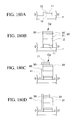
- a metallic layer 1010 is formed on the glass plate 1001 , and excepting the scanning line 1011 (not shown) and the gate electrode 1012 extending from the scanning line to the TFT section Tf, the scanning terminal 1015 extending to the outer periphery section Ss, and the common accumulation electrode 1072 of the accumulation capacitance section Cp, the metallic layer 1010 is removed by etching.
- Step 2 As shown in FIG. 184B, laminating successively the gate insulation layer 1002 and the semiconductor layer 1020 , comprised by an amorphous silicon layer 1021 and an n + amorphous silicon layer 1022 , on the transparent insulation substrate plate, the semiconductor layer 1020 is removed excepting the TFT section Tf.
- Step 3 As shown in FIG. 184C, a metallic layer 1030 is formed on the transparent insulation substrate plate, and excepting the signal line 1031 , signal line terminal 1035 extending from the signal line to the outer peripheral section Ss, drain electrode 1032 , and source electrode 1033 , the metallic layer 1030 is removed by etching. Next, using the remaining metallic layer as masking, the n + amorphous silicon layer 1022 exposed at the channel gap 1023 in the TFT section is removed.
- a protective insulation layer 1003 is formed on the transparent insulation substrate plate, and a first opening 1061 reaching the signal line terminal 1035 by punching through the protective insulation layer 1003 in the outer peripheral section Ss, a second opening 1062 reaching the source electrode 1033 by punching through the protective insulation layer 1003 in the TFT section Tf, and a third opening 1063 reaching the scanning line terminal 1015 by punching through the protective insulation layer 1003 and the gate insulation layer 1002 in the outer peripheral section Ss are formed by etching.
- a transparent conductive layer 1040 is formed on the transparent insulation substrate plate, and excepting the pixel electrode 1041 extending to the window section Wd and connected to the source electrode 1033 through the second opening 1062 in the TFT section Tf, the accumulation capacitance electrode 1071 extending from the pixel electrode above the common accumulation electrode 1072 in the accumulation capacitance section Cp, the terminal pad 1095 exposed above the signal line terminal 1035 through the first opening 1061 and above the scanning line terminal 1015 through the third opening 1063 in the outer peripheral section Ss, the transparent conductive layer 1040 is removed by etching to complete the processing steps.
- peripheral circuits such as protective transistors
- drop in yield caused by etching operation has also been experienced, which is caused by infiltration corrosion of needed underlying layers which should have been left intact.
- step 1 scanning line and gate electrode are formed, in step 2 , after forming films for gate insulation layer and semiconductor layer and metallic layer, excepting the regions where signal line and drain electrode and source electrode are continued, the metallic layer and the semiconductor layer are removed by etching, in step 3 , after forming the transparent conductive layer, the transparent conductive layer and channel gap metallic layer are removed by etching except the signal line, the drain electrode, source electrode and pixel electrode extending from the source electrode, and next, removing the n + amorphous silicon layer using the remaining transparent conductive layer as masking, and in step 4 , after forming a protective insulation layer, the protective insulation layer on the pixel electrode is removed by etching, thus constituting a process comprised by four steps.
- this method because the gate metallic layer is formed, in step 2 forming films for gate insulation layer and semiconductor layer and metallic layer, excepting the regions where signal line and drain electrode and source electrode are continued, the metallic layer and the semiconductor layer are removed by etching, in step 3 , after forming the transparent conductive layer,
- a Japanese Unpublished Patent Application, First Publication, Hei 7-175084 discloses a process in which, in step 1 , scanning line and gate electrode are formed, in step 2 , after forming films of gate insulation layer and semiconductor layer, excepting the semiconductor layer of the TFT section, a gate insulation layer and semiconductor layer are removed by etching in step 3 , after forming the transparent conductive layer, excepting the signal line, pixel electrode, drain electrode and source electrode, the transparent conductive layer is removed next, using the remaining transparent conductive layer as masking, n + amorphous silicon layer is removed, and in step 4 , after forming a protective insulation layer, the protective insulation layer above the pixel electrode is removed, thus constituting a process comprised by four steps.
- this method has a problem of quality of displays and the yield, because the signal lines, drain electrodes, source electrodes and others are made only of transparent conductive layer (ITO, indium tin oxide) that has high resistance and susceptible to causing film defects.
- ITO transparent conductive layer
- a Japanese Unpublished Patent Application, First Publication, Hei 8-146462 proposes, in step 1 , to form scanning line and gate electrode and in step 2 , after forming films of the gate insulation layer, the semiconductor layer and metallic silicide layer, excepting the portions linking the signal line, drain electrode and source electrode, the metallic silicide layer, semiconductor layer, and gate insulation layer are removed by etching and in step 3 , after forming films of the transparent conductive layer and metallic layer, excepting the signal line, drain electrode, source electrode and the pixel electrode linking the signal line, drain electrode and source electrode and pixel electrode linked to the source electrode, the metallic layer and the transparent conductive layer are removed by etching and next, using the remaining metallic layer as masking, removing the n + amorphous silicon layer, and in step 4 , after forming a protective insulation layer, the protective insulation layer above the pixel electrodes and the metallic layer are removed by etching, thereby constituting a 4-step process.
- the present invention is provided to resolve such forgoing problems, and therefore, the object is to provide an active matrix substrate plate that can be produced with good yield and superior properties using a lesser number of manufacturing steps and its manufacturing methods.
- the active matrix substrate plate according to the first aspect of this invention is formed on a transparent insulating substrate plate having an array of pixel regions, wherein each pixel region contains a scanning line and a signal line and is surrounded by the scanning line and the signal line crossing each other at right angles, and in each pixel region is formed an inverted staggered structure thin film transistor comprised by a gate electrode, an island-shaped semiconductor layer opposing the gate electrode across a gate insulation layer, a pair of drain electrode and source electrode separated by a channel gap formed above the semiconductor layer, such that a pixel electrode is formed in a window section surrounded by the scanning line and the signal line for transmitting light, and the gate electrode is connected to the scanning line, the drain electrode is connected to the signal line, and the source electrode is connected to the pixel electrode (the TN-type active matrix substrate plate), wherein, the signal line, the source electrode and the drain electrode in all cases are formed by laminating a metallic layer on top of a transparent conductive layer, and the transparent conductive layer below the
- This TN-type active matrix substrate plate can be manufactured in four steps so that the productivity and the yield are improved.
- the signal line is comprised by laminating a metallic layer and the transparent conductive layer, wiring resistance of the signal line can be reduced and the yield drop due to severing of lines can be suppressed, and because the source electrode and the pixel electrode are comprised integrally by the transparent conductive layer, an increase in the contact resistance can be suppressed and the performance properties are enhanced.
- the active matrix substrate plate according to the second aspect of this invention is formed on a transparent insulating substrate plate by a plurality of scanning lines alternating with a plurality of common wiring lines, and a pixel region, containing a scanning line and a signal line is surrounded by the scanning line and the signal line crossing at right angles to each other, is arrayed in such a way that in each pixel region is formed an inverted staggered structure thin film transistor comprised by a gate electrode, an island-shaped semiconductor layer opposing the gate electrode across a gate insulation layer, a pair of drain electrode and source electrode separated by a channel gap formed above the semiconductor layer, such that in a window section surrounded by the scanning line and the signal line are formed a pixel electrode of a comb teeth shape and a common electrode of a comb teeth shape connecting to a common wiring line and opposing the pixel electrode, so that the gate electrode is connected to the scanning line, the drain electrode is connected to the signal line, and the source electrode is connected to the pixel electrode, so as to generate a horizontal
- This IPS-type active matrix substrate plate can be made in four steps so that the productivity and the yield are improved.
- the end section of the common wiring line extends outside of the end section of one perimeter section of the scanning line in the one perimeter section or opposing perimeter sections of the transparent insulating substrate plate, and the end section of the common wiring is linked to each other by the common wiring linking line, and the common wiring line terminal section is formed on the linking line, and therefore, regardless of whether the scanning line terminal is formed on one side or both sides of the transparent insulating substrate plate, the common wiring terminal can be led out, so that the IPS-type active matrix substrate plate can be produced independently.
- the difference in the height of the common electrode and pixel electrode section is made small, so that orientation control in the paneling step is facilitated.
- the TN-type active matrix substrate plate according to the third aspect of this invention is comprised in such a way that a semiconductor layer of a same shape as the signal line is formed on a layer below the signal line and both the semiconductor layer and the signal line are covered by a transparent conductive layer, and the source electrode and the drain electrode are formed by laminating the transparent conductive layer on top of a metallic layer, and the transparent conductive layer in an upper layer of the source electrode extending above the gate insulation layer of the window section to form the pixel electrode.
- This TN-type active matrix substrate plate can be manufactured in four steps so that the productivity and the yield are improved.
- the signal line is comprised by a metallic layer and the transparent conductive layer
- wiring resistance of the signal line can be reduced and the yield drop due to severing of lines can be suppressed
- the source electrode and the pixel electrode are comprised integrally by the transparent conductive layer, an increase in the contact resistance can be suppressed and the performance properties are enhanced.
- the lateral surface of semiconductor layer below the signal line is covered by the transparent conductive layer, when etching the n + amorphous silicon layer forming the TFT channel, infiltration corrosion of the amorphous layer of the semiconductor layer in the lateral direction can be prevented, thereby preventing difficulty of orientation control caused by improper covering by the protective insulation layer.
- the lateral surface of the metallic layer of the signal line is covered by the transparent conductive layer, when etching the transparent conductive layer, a photo-resist coating is covering the metallic layer of the signal line and the semiconductor layer. Therefore, even if debris or foreign particles are present on the metallic layer, etching solution does not infiltrate into the boundary of the transparent conductive layer and the metallic layer, to prevent severing of the signal line.
- the TN-type active matrix substrate plate according to the fourth aspect of this invention is comprised in such a way that a semiconductor layer formed in a layer below the signal line is formed in a cross sectional shape so as to have a wider bottom, and the upper layer of the -shaped semiconductor layer, a metallic layer and a transparent conductive layer comprising the signal line are formed so that the lateral surfaces are aligned, and the source electrode and the drain electrode are formed by laminating the transparent conductive layer on top of the metallic layer, and the pixel electrode is formed by the transparent conductive layer in an upper layer of the source electrode extending above the gate insulation layer of the window section.
- This TN-type active matrix substrate plate can be manufactured in four steps so that the productivity and the yield are improved.
- the signal line is comprised by a metallic layer and the transparent conductive layer
- wiring resistance of the signal line can be reduced and the yield drop due to severing of lines can be suppressed
- the source electrode and the pixel electrode are comprised integrally by the transparent conductive layer, an increase in the contact resistance can be suppressed and the properties are enhanced.
- the metallic layer of the signal line can be etched using the transparent conductive layer as masking so that dimensional control of the signal line is facilitated.
- the active matrix substrate plate according to the fifth aspect of this invention is a TN-type according to one of the second to the fourth aspects of this invention, wherein a thickness of an ohmic contact layer formed in an upper layer of the semiconductor layer formed in a layer below the source electrode and the drain electrode is 3-6 nm.
- the ohmic contact layer above the semiconductor layer can be etched at the same time, and the thickness of the semiconductor layer can be made thin, so that the productivity is increased and the resistance in the vertical direction of the semiconductor layer can be lowered to improve the writing capability of the TFT.
- the active matrix substrate plate according to the sixth aspect of this invention relates to one of the first to the fourth aspects of this invention, wherein the scanning line is comprised by a single film layer of Al or an alloy of primarily Al, or a lamination of a high melting point metal and an upper layer of Al or an alloy of primarily Al.
- These active matrix substrate plates enable to reduce wiring resistance of the scanning line and to secure reliability of connection of the scanning line driver at the scanning line terminal section.
- the active matrix substrate plate according to the seventh aspect of this invention relates to one of the first to the fourth aspects of this invention, wherein the scanning line is comprised by a lamination of conductive films of not less than two layers, and an uppermost layer of the lamination is comprised by a nitride film of a metal or a transparent conductive film.
- the active matrix substrate plates according to the eighth and the ninth aspects of this invention relate to the second and the fifth aspects of this invention, respectively, wherein the signal line is comprised by a lamination of a high melting point metal and an upper layer of Al or an alloy of primarily Al.
- These active matrix substrate plates enable to reduce wiring resistance of the signal line and to secure reliability of connection of the signal line driver at the signal line terminal section.
- the active matrix substrate plates according to the 10th and the 11th aspects of this invention relate to the second and the fifth aspects of this invention, respectively, wherein the scanning line is comprised by a lamination of conductive films of not less than two layers, and an uppermost layer of the lamination is comprised by a nitride film of a metal or a transparent conductive film.
- the active matrix substrate plates according to the 12th to the 14th aspects of this invention relate to the seventh, the 10th, and the 11th aspects of this invention, respectively, wherein the nitride film of a metal is comprised by a nitride film of Ti, Ta, Nb, Cr, or a nitride film of an alloy comprised primarily of at least one metal selected from Ti, Ta, Nb, Cr.
- the active matrix substrate plates according to the 15th to the 17th aspects of this invention relate to the 12th to the 14th aspects of this invention, respectively, wherein the nitride film of a metal has a nitrogen concentration of not less than 25 atomic percent.
- the method for manufacturing according to the 18th aspect of this invention is for a TN-type active matrix substrate plate, wherein in a first step, forming a conductor layer on the transparent insulation substrate plate, and excepting the scanning line, a scanning line terminal section formed in a scanning line start end, and in each pixel region, the gate electrode extending from the scanning line to the thin film transistor section or sharing a portion of the scanning line, removing the conductor layer by etching; in a second step, laminating successively on the transparent insulation substrate plate, a gate insulation layer and a semiconductor layer comprised by an amorphous silicon layer and an n + amorphous silicon layer, and excepting the thin film transistor section, removing the semiconductor layer by etching; in a third step, laminating successively on the transparent insulation substrate plate, a transparent conductive layer and a metallic layer, and excepting the signal line, a signal line terminal section formed in the signal line start end section, and in each pixel region, the drain electrode extending from the signal line to the thin film
- This method enables to manufacture the active matrix substrate plate according to the first aspect of this invention in four steps.
- the method for manufacturing according to the 19th aspect of this invention is for an IPS-type active matrix substrate plate, wherein, in a first step, forming a first conductor layer on the transparent insulation substrate plate, and excepting the scanning line, the scanning line terminal section formed in a scanning line start end, and, a common wiring line whose end section at least in one perimeter section of the transparent insulation substrate plate extends outside of an end section of the scanning line in the same perimeter section, a common wiring linking line for connecting end sections of the common wiring line, and in each pixel region, the gate electrode sharing a portion of the scanning line, and a plurality of common electrodes extending from the common wiring line, removing the first conductor layer by etching; in a second step, laminating successively on the transparent insulation substrate plate, a gate insulation layer and a semiconductor layer comprised by an amorphous silicon layer and an n + amorphous silicon layer, and excepting the portion of the scanning line to form the gate electrode for the thin film transistor section in each pixel region, removing the semiconductor
- This method of manufacturing an active matrix substrate plate enables to manufacture the active matrix substrate plate according to the second aspect of this invention in four steps.
- the method for manufacturing according to the 20th aspect of this invention is for a TN-type active matrix substrate plate, wherein, in a first step, forming a conductor layer on the transparent insulation substrate plate, and excepting the scanning line, a scanning line terminal section formed in a scanning line start end, and in each pixel region, the gate electrode extending from the scanning line to the thin film transistor section or sharing a portion of the scanning line, removing the conductor layer by etching; in a second step, laminating successively on the transparent insulation substrate plate, a gate insulation layer and a semiconductor layer comprised by an amorphous silicon layer and an n + amorphous silicon layer, and a metallic layer, and excepting the signal line or a portion covering the signal line, a signal line terminal section formed on the signal line start end section, and in each pixel region, a protrusion section extending from the signal line to the pixel electrode through the thin film transistor section, removing the metallic layer and the semiconductor layer by etching; in a third step, forming
- This method enables to manufacture the active matrix substrate plate according to the third or the fourth aspect of this invention in four steps.
- the method for manufacturing according to the 21st aspect of this invention is for a TN-type active matrix substrate plate, wherein, in a first step, forming a conductor layer on the transparent insulation substrate plate, and excepting the scanning line, a scanning line terminal section formed in a scanning line start end, and in each pixel region, the gate electrode extending from the scanning line to the thin film transistor section or sharing a portion of the scanning line, removing the conductor layer by etching; in a second step, laminating successively on the transparent insulation substrate plate, a gate insulation layer and a semiconductor layer comprised by an amorphous silicon layer, and forming an n + amorphous silicon layer on the semiconductor layer by doping with a group V element, and then depositing a metallic layer, and excepting the signal line or a portion covering the signal line, a signal line terminal section formed on a signal line start end section, and in each pixel region, a protrusion section extending from the signal line to the pixel electrode through the thin film transistor section, removing
- This method enables to manufacture the active matrix substrate plate according to the fifth aspect of this invention in four steps.
- the method for manufacturing according to the 22nd aspect of this invention is for an IPS-type active matrix substrate plate, wherein, in a first step, forming a conductor layer on the transparent insulation substrate plate, and excepting the scanning line, a scanning line terminal section formed in a scanning line start end, and, a common wiring line whose end section at least in one perimeter section of the transparent insulation substrate plate extends outside of an end section of the scanning line in the same perimeter section, a common wiring line linking line for connecting end sections of the common wiring lines, and in each pixel region, the gate electrode sharing a portion of the scanning line, and a plurality of common electrodes extending from the common wiring line, removing the conductor layer by etching; in a second step, laminating successively on the transparent insulation substrate plate, a gate insulation layer and a semiconductor layer comprised by an amorphous silicon layer and an n + amorphous silicon layer, and a metallic layer, and excepting the signal line or the portion covering the signal line, a signal line terminal section formed in the signal
- This method enables to manufacture the active matrix substrate plate according to the second aspect of this invention in four steps.
- the method for manufacturing according to the 23rd aspect of this invention is for an IPS-type active matrix, wherein, in a first step, forming a conductor layer on the transparent insulation substrate plate, and excepting the scanning line, a scanning line terminal section formed in a scanning line start end, and, a common wiring line whose end section at least in one perimeter section of the transparent insulation substrate plate extends outside of an end section of the scanning line in the same perimeter section, a common wiring line linking line for connecting end sections of the common wiring lines, and in each pixel region, the gate electrode sharing a portion of the scanning line, and a plurality of common electrodes extending from the common wiring line, removing the conductor layer by etching; in a second step, laminating successively on the transparent insulation substrate plate, a gate insulation layer and a semiconductor layer comprised by an amorphous silicon layer, and forming an n + amorphous silicon layer on the semiconductor layer by doping with a group V element, and then depositing a metallic layer, and excepting the signal line
- This method enables to manufacture the active matrix substrate plate according to the fifth aspect of this invention in four steps.
- the method for manufacturing according to the 24th aspect of this invention is for an IPS-type active matrix substrate plate, wherein, in a first step, forming a conductor layer on the transparent insulation substrate plate, and excepting the scanning line, a scanning line terminal section formed in a scanning line start end, and a common wiring line whose end section at least in one perimeter section of the transparent insulation substrate plate extends outside of an end section of the scanning line in the same perimeter section, a common wiring line linking line for connecting end sections of the common wiring lines, and in each pixel region, the gate electrode sharing a portion of the scanning line, and a plurality of common electrodes extending from the common wiring line, removing the conductor layer by etching; in a second step, laminating successively on the transparent insulation substrate plate, a gate insulation layer and a semiconductor layer comprised by an amorphous silicon layer and an n + amorphous silicon layer, and a metallic layer, and excepting the signal line or a portion covering the signal line, a signal line terminal section formed in a
- This method enables to manufacture the active matrix substrate plate according to the second aspect of this invention in four steps.
- the method for manufacturing according to the 25th aspect of this invention is for an IPS-type active matrix substrate plate, wherein, in a first step, forming a conductor layer on the transparent insulation substrate plate, and excepting the scanning line, a scanning line terminal section formed in a scanning line start end, and a common wiring line whose end section at least in one perimeter section of the transparent insulation substrate plate extends outside of an end section of the scanning line in the same perimeter section, a common wiring line linking line for connecting end sections of the common wiring lines, and in each pixel region, the gate electrode sharing a portion of the scanning line, and a plurality of common electrodes extending from the common wiring line, removing the conductor layer by etching; in a second step, laminating successively on the transparent insulation substrate plate, a gate insulation layer and a semiconductor layer comprised by an amorphous silicon layer, and forming an n + amorphous silicon layer on the semiconductor layer by doping with a group V element, and then depositing a metallic layer, and excepting the signal line
- This method enables to manufacture the active matrix substrate plate according to the fifth aspect of this invention in four steps.
- the method according to the 26th aspect of this invention relates to manufacturing the active matrix substrate plate according to one of the 18th to the 25th aspects of this invention, wherein in the first step, the conductor layer is formed by laminating Al or an alloy of primarily Al, or by laminating a high melting point metal and an upper layer of Al or an alloy of primarily Al on the transparent insulation substrate plate.
- the method according to the 27th aspect of this invention relates to manufacturing the active matrix substrate plate according to one of the 18th to the 25th aspects of this invention, wherein in the first step, the conductor layer is formed by laminating not less than one layer of a conductive film and an upper layer of a nitride film of a metal or a transparent conductive film on the transparent insulation substrate plate.
- the method according to the 28th aspect of this invention relates to manufacturing the active matrix substrate plate according to one of the 19th, the 22nd to the 25th aspects of this invention, wherein in the third step, the second conductor layer or the second metallic layer is formed by laminating a high melting point metal and an upper layer of Al or an alloy of primarily Al.
- the method according to the 29th aspect of this invention relates to manufacturing the active matrix substrate plate according to the 19th aspect of this invention, wherein, in the third step, the second conductor layer is formed by laminating not less than one layer of a conductive film and an upper layer of a nitride film of a metal or the transparent conductive film.
- This method of manufacturing an active matrix substrate plate enables to secure reliability of connection of the signal line driver at the signal line terminal section.
- the methods according to the 30th and the 31st aspects of this invention relate to manufacturing the active matrix substrate plate according to the 27th and the 29th aspect of this invention, respectively, wherein the nitride film of a metal is comprised by a nitride film of Ti, Ta, Nb, Cr or a nitride film of an alloy comprised primarily of at least one metal selected from Ti, Ta, Nb, Cr.
- This method of manufacturing an active matrix substrate plate enables to secure reliability of connection at the scanning line terminal section and at the signal line terminal section.
- the methods according to the 32nd and the 33rd aspects of this invention relate to manufacturing the active matrix substrate plate according to the 30th and the 31st aspects of this invention, respectively, wherein the nitride film of a metal is formed by reactive sputtering so as to produce a nitrogen concentration of not less than 25 atomic percent.
- This method of manufacturing an active matrix substrate plate enables to secure reliability of connection at the scanning line terminal and at the signal line terminal in a good condition.
- the method according to the 34th aspect of this invention relates to manufacturing the active matrix substrate plate according to one of the first to the fourth aspects of this invention, wherein the signal line is connected to each other by a high resistance line comprised by amorphous silicon.
- the method according to the 35th aspect of this invention relates to manufacturing the active matrix substrate plate according to one of the first to the fourth aspects of this invention, wherein the signal line is connected to each other across an amorphous silicon layer above a floating electrode formed concurrently with the scanning line.
- This active matrix substrate plate has the same benefits as the above substrate plate.
- the methods according to the 36th and the 37th aspects of this invention relate to manufacturing the active matrix substrate plate according to one of the 34th and the 35th aspects of this invention, respectively, wherein adjacent signal lines have one pair or a plurality of pairs of opposing protrusion sections in the input side with respect to a pixel region, and the protrusion section is connected to each other by the amorphous silicon layer.
- the method according to the 38th aspect of this invention relates to manufacturing the active matrix substrate plate according to one of the first to the fourth aspects of this invention, wherein the signal line is connected to a common wiring line by a high resistance line comprised by amorphous silicon.
- the method according to the 39th aspect of this invention relates to manufacturing the active matrix substrate plate according to one of the first to the fourth aspects of this invention, wherein the signal line is electrically connected to a common wiring line across an amorphous silicon layer above a floating electrode formed concurrently with the scanning line.
- the methods according to the 40th and the 41st aspects of this invention relate to manufacturing the active matrix substrate plate according to the 38th and the 39th aspects of this invention, respectively, wherein the signal line and the common wiring line formed on the same layer as the signal line, or signal line linking line connected to the common wiring line formed on the same layer as the scanning line and formed on the same layer as the signal line, have one pair or a plurality of pairs of opposing protrusion sections at the signal line end, and the protrusion section is connected to each other by an amorphous silicon layer.
- the active matrix substrate plate according to the 42nd aspect of this invention is formed on a transparent insulating substrate plate having an array of pixel regions, wherein each pixel region contains a scanning line and a signal line and is surrounded by the scanning line and the signal line crossing each other at right angles, and in each pixel region is formed an inverted staggered structure thin film transistor comprised by a gate electrode, an island-shaped semiconductor layer opposing the gate electrode across a gate insulation layer, a pair of drain electrode and source electrode separated by a channel gap formed above the semiconductor layer, such that a pixel electrode is formed in a window section surrounded by the scanning line and the signal line for transmitting light, and the gate electrode is connected to the scanning line, the drain electrode is connected to the signal line, and the source electrode is connected to the pixel electrode, wherein, the drain electrode and the source electrode are formed by laminating a metallic layer on top of a transparent conductive layer, and a lamination of the transparent conductive layer and the metallic layer of the source electrode descends vertically to the transparent insulation substrate plate
- This active matrix substrate plate can be manufactured in four steps so that the productivity and the yield are improved.
- this active matrix substrate plate because the conductor layer formed together with the scanning line on top of the transparent insulation substrate plate, excepting the connection section to the transparent conductive layer, is totally covered by the gate insulation layer, during etching of metallic layer of the signal line or the transparent conductive layer, corrosion problems of circuit elements such as the scanning lines in the lower layer and gate electrodes or shorting of scanning lines and signal lines are prevented, and the yield is improved.
- protective transistor can be fabricated so that the TFT in the pixel region can be prevented from unexpected electrical shock during manufacturing. Also, insulation breakdown between the scanning lines and signal lines can be prevented, and the yield is improved.
- the signal line is formed by laminating a metallic layer and the transparent conductive layer, the wiring resistance of the signal line can be lowered, and also, a drop in yield caused by severing of the signal line can be suppressed, and because the source electrode and the pixel electrode are formed integrally using the transparent conductive layer, an increase in contact resistance can be suppressed and the reliability is improved.
- the active matrix substrate plate according to the 43rd aspect of this invention is formed on a transparent insulating substrate plate by a plurality of scanning lines alternating with a plurality of common wiring lines, and a pixel region, containing a scanning line and a signal line is surrounded by the scanning line and the signal line crossing at right angles to each other, is arrayed in such a way that in each pixel region is formed an inverted staggered structure thin film transistor comprised by a gate electrode, an island-shaped semiconductor layer opposing the gate electrode across a gate insulation layer, a pair of drain electrode and source electrode separated by a channel gap formed above the semiconductor layer, such that in a window section surrounded by the scanning line and the signal line are formed a pixel electrode of a comb teeth shape and a common electrode of a comb teeth shape connecting to a common wiring line and opposing the pixel electrode, so that the gate electrode is connected to the scanning line, the drain electrode is connected to the signal line, and the source electrode is connected to the pixel electrode, so as to generate
- This IPS-type active matrix substrate plate can be manufactured in four steps so that the productivity and the yield are improved.
- protective transistor can be fabricated so that the TFT in the pixel region can be prevented from unexpected electrical shock during manufacturing. Also, insulation breakdown between the scanning lines and signal lines can be prevented, and the yield is improved
- the active matrix substrate plate according to the 44th aspect of this invention is formed on a transparent insulating substrate plate having an array of pixel regions, wherein each pixel region contains a scanning line and a signal line and is surrounded by the scanning line and the signal line crossing each other at right angles, and in each pixel region is formed an inverted staggered structure thin film transistor comprised by a gate electrode, an island-shaped semiconductor layer opposing the gate electrode across a gate insulation layer, a pair of drain electrode and source electrode separated by a channel gap formed above the semiconductor layer, such that a pixel electrode is formed in a window section surrounded by the scanning line and the signal line for transmitting light, and the gate electrode is connected to the scanning line, the drain electrode is connected to the signal line, and the source electrode is connected to the pixel electrode, wherein, the drain electrode and the source electrode are both formed by laminating the transparent conductive layer on top of a metallic layer, and the transparent conductive layer above the source electrode descends vertically to the transparent insulation substrate plate so as to cover a lateral surface
- This TN-type active matrix substrate plate can be manufactured in four steps so that the productivity and the yield are improved.
- this active matrix substrate plate because the conductor layer formed together with the scanning line on top of the transparent insulation substrate plate, excepting the connection section to the transparent conductive layer, is totally covered by the gate insulation layer, during etching of metallic layer of the signal line or the transparent conductive layer, corrosion problems of circuit elements such as the scanning lines in the lower layer and gate electrodes or shorting of scanning lines and signal lines are prevented, and the yield is improved.
- protective transistor can be fabricated so that the TFT in the pixel region can be prevented from unexpected electrical shock during manufacturing. Also, insulation breakdown between the scanning lines and signal lines can be prevented, and the yield is improved
- the signal line is formed by laminating a metallic layer and the transparent conductive layer, the wiring resistance of the signal line can be lowered, and also, a drop in yield caused by severing of the signal line can be suppressed, and because the source electrode and the pixel electrode are formed integrally using the transparent conductive layer, an increase in contact resistance can be suppressed and the reliability is improved.
- the active matrix substrate plate according to the 45th aspect of this invention relates to one according to the 44th aspect of this invention, wherein a thickness of an ohmic contact layer formed in an upper layer of the semiconductor layer formed in a layer below the source electrode and the drain electrode is 3-6 nm.
- the ohmic contact layer above the semiconductor layer can be etched at the same time, and the thickness of the semiconductor layer can be made thin, so that the productivity is increased and the writing capability of the TFT can be improved.
- the active matrix substrate plate according to the 46th aspect of this invention relates to one according to the 43rd aspect of this invention, wherein the signal line is comprised by a lamination of a high melting point metal laminated and an upper layer of Al or an alloy of primarily Al.
- This active matrix substrate plate enables to reduce wiring resistance of the signal line and to secure reliability of connection of the signal line driver at the signal line terminal section.
- the active matrix substrate plate according to the 47th aspect of this invention relates to one according to the 43rd aspect of this invention, wherein the signal line is comprised by a lamination of conductive films of not less than two layers, and an uppermost layer of the lamination is comprised by a nitride film of a metal or a transparent conductive film.
- This active matrix substrate plate enables to secure reliability of connection of the signal line driver at the signal line terminal section.
- the active matrix substrate plate according to the 48th aspect of this invention relates to one according to the 47th aspect of this invention, wherein the nitride film of a metal is comprised by a nitride film of Ti, Ta, Nb, Cr or a nitride film of an alloy comprised primarily of at least one metal selected from Ti, Ta, Nb, Cr.
- This active matrix substrate plate provides the same beneficial effects as described above.
- the active matrix substrate plate according to the 49th aspect of this invention relates to one according to the 48th aspect of this invention, wherein the nitride film of a metal has a nitrogen concentration of not less than 25 atomic percent.
- This active matrix substrate plate enables to secure reliability of connection of the signal line driver at the signal line terminal section in a good condition.
- the active matrix substrate plate according to the 50th aspect of this invention relates to one according to one of the 42nd to the 45th aspects of this invention, wherein a portion of both lateral surface of the semiconductor layer extending in the direction of the channel gap of the thin film transistor section is covered by the protective insulation layer.
- the active matrix substrate plate according to the 51st aspect of this invention relates to one according to one of the 42nd to the 45th aspects of this invention, wherein the scanning line is comprised of a conductive film comprised by a lamination of not less than two layers, and an uppermost layer of the lamination serves as an etching protective layer for the conductor layer formed in a lower layer.
- These active matrix substrate plates are able to prevent infiltration corrosion caused by the etching solution infiltrating through the opening section punched through the gate insulation layer above the gate electrode and the semiconductor layer, when etching the metallic layer of the signal line or the transparent conductive layer, to corrode the conductor layer in a layer below the gate electrode or the scanning line, thereby improving the yield.
- the active matrix substrate plate according to the 52nd aspect of this invention relates to one according to the 51st aspect of this invention, wherein at least one layer of the conductor film in a lower layer is comprised of Al or an alloy of primarily Al, and a conductive film in the uppermost layer is comprised of Ti, Ta, Nb, or an alloy comprised primarily of at least one of preceding elements, or Ti, Ta, Nb, Cr, or a nitride film of an alloy comprised primarily of at least one metal selected from Ti, Ta, Nb, Cr.
- This active matrix substrate plate provides the same beneficial effects as described above.
- connection section is formed to connect the first conductor layer where the scanning line is formed and the second conductor layer where the signal line is formed, and the connection section is disposed so as not to superimpose on an opening section of the protective insulation layer.
- the active matrix substrate plate according to the 42nd aspect of this invention is constructed so that, even if a same metal is used or different metals are used for the first conductor layer and second conductor layer, if the first conductor layer is not resistant to etching of the metallic layer in the second conductor layer, after the protective insulation layer is opened and when the metal layer above the transparent conductive layer is to be removed by etching, it is possible to prevent the etching solution to infiltrate through the transparent conductive layer at the connection section and corrode the first conductor layer, and the yield is improved.
- the active matrix substrate plates according to the 44th and the 45th aspects of this invention are constructed so that, when at least one layer of the first conductor layer is comprised by Al or an alloy of primarily Al, and if a hydrofluoric type acid is used to etch the opening section in the protective insulation layer, during etching operation on the protective insulation layer, it is possible to prevent the etching solution to infiltrate through the transparent conductive layer to corrode Al or an alloy of primarily Al in the first conductor layer, thereby improving the yield.
- the active matrix substrate plate according to the 54th aspect of this invention relates to one according to the 42nd or the 43rd aspect of this invention, wherein the first conductor layer where the scanning line is formed and the second conductor layer where the signal line is formed are connected directly through an opening section punched through the gate insulation layer and the semiconductor layer.
- These active matrix substrate plates can be manufactured in four steps, because the first conductor layer and the second conductor layer can be electrically connected according to the structure described, so that the productivity and the yield are improved.
- protective transistor can be fabricated so that the TFT in the pixel region can be prevented from unexpected electrical shock during manufacturing. Also, insulation breakdown between the scanning lines and signal lines can be prevented, and the yield is improved.
- the active matrix substrate plate according to the 55th aspect of this invention relates to one according to the 44th or the 45th aspect of this invention, wherein the first conductor layer where the scanning line is formed and the second conductor layer where the signal line is formed are connected directly the transparent conductive layer through an opening section punched through the gate insulation layer and the semiconductor layer.
- the active matrix substrate plate according to the 56th aspect of this invention relates to one according to the 42nd aspect of this invention, wherein a conductor layer of a forestage scanning line that opposes each other across a lamination comprised by the gate insulation layer and the semiconductor layer and the transparent conductive layer extending from the pixel electrode form an accumulation capacitance section, and in this accumulation capacitance section, lateral end surfaces of the transparent conductive layer and the semiconductor layer are aligned.
- This active matrix substrate plate improves productivity and yield because it can be manufactured in four steps due to the structure of the accumulation capacitance section.
- the active matrix substrate plate according to the 57th aspect of this invention relates to one according to the 44th or the 45th aspect of this invention, wherein a conductor layer of a forestage scanning line that opposes each other across a lamination comprised by the gate insulation layer and the semiconductor layer and the metallic layer in the pixel region and the transparent conductive layer laminated above form an accumulation capacitance section, and in this accumulation capacitance section, lateral end surfaces of the transparent conductive layer and the metallic layer and the semiconductor layer are aligned.
- This active matrix substrate plate provides the same beneficial effects as described above.
- the method according to the 58th aspect of this invention relates to manufacturing a TN-type active matrix substrate plate, wherein, in a first step, forming a conductor layer on the transparent insulation substrate plate, and excepting at least the scanning line, a scanning line terminal section formed in a scanning line start end, and in each pixel region, the gate electrode extending from the scanning line to the thin film transistor section or sharing a portion of the scanning line, removing the conductor layer by etching; in a second step, laminating successively on the transparent insulation substrate plate, a gate insulation layer and a semiconductor layer comprised by an amorphous silicon layer and an n + amorphous silicon layer, and excepting a specific opening section formed above the conductor layer in the first step, and leaving so as to cover at least an upper surface of the conductor layer and an entire lateral surface with the gate insulation layer, removing the semiconductor layer and the gate insulation layer by etching; in a third step, laminating successively on the transparent insulation substrate plate, a transparent conductive layer and
- This method enables to manufacture the active matrix substrate plate according to the 42nd aspect of this invention in four steps.
- the method according to the 59th aspect of this invention relates to manufacturing a TN-type active matrix substrate plate, wherein in a first step, forming a conductor layer on the transparent insulation substrate plate, and excepting at least the scanning line, and in each pixel region, the gate electrode extending from the scanning line to the thin film transistor section or sharing a portion of the scanning line, removing the conductor layer by etching; in a second step, laminating successively on the transparent insulation substrate plate, a gate insulation layer and a semiconductor layer comprised by an amorphous silicon layer and an n + amorphous silicon layer, and excepting a specific opening section formed above the conductor layer in the first step, and leaving so as to cover at least an upper surface of the conductor layer and an entire lateral surface with the gate insulation layer, removing the semiconductor layer and the gate insulation layer by etching; in a third step, laminating successively on the transparent insulation substrate plate, a transparent conductive layer and a metallic layer, and excepting the signal line, a signal line
- This method enables to manufacture the active matrix substrate plate according to the 42nd aspect of this invention in four steps.
- the method of manufacturing an active matrix substrate plate according to the 60th aspect of this invention relates a TN-type active matrix substrate plate, wherein, in a first step, forming a conductor layer on the transparent insulation substrate plate, and excepting at least the scanning line, a scanning line terminal section formed in a scanning line terminal section location, and in each pixel region, the gate electrode extending from the scanning line to the thin film transistor section or sharing a portion of the scanning line, a lower layer signal line formed non-contactingly between adjacent scanning lines to form a portion of the signal line, removing the conductor layer by etching; in a second step, laminating successively on the transparent insulation substrate plate, a gate insulation layer and a semiconductor layer comprised by an amorphous silicon layer and an n + amorphous silicon layer, and excepting a specific opening section formed above the conductor layer in the first step, and leaving so as to cover at least an upper surface of the conductor layer and an entire lateral surface with the gate insulation layer, removing the semiconductor layer and the gate insulation layer
- This method enables to manufacture the active matrix substrate plate according to the 42nd aspect of this invention in four steps.
- the method of manufacturing an active matrix substrate plate according to the 61st aspect of this invention relates to a TN-type active matrix substrate plate, wherein, in a first step, forming a conductor layer on the transparent insulation substrate plate, and excepting at least the scanning line, and in each pixel region, the gate electrode extending from the scanning line to the thin film transistor section or sharing a portion of the scanning line, a lower layer signal line formed non-contactingly between adjacent scanning lines to form a portion of the signal line, removing the conductor layer by etching; in a second step, laminating successively on the transparent insulation substrate plate, a gate insulation layer and a semiconductor layer comprised by an amorphous silicon layer and an n + amorphous silicon layer, and excepting a specific opening section formed above the conductor layer in the first step, and leaving so as to cover at least an upper surface of the conductor layer and an entire lateral surface with the gate insulation layer, removing the semiconductor layer and the gate insulation layer by etching; in a third step, lamin
- This method enables to manufacture the active matrix substrate plate according to the 42nd aspect of this invention in four steps.
- the method for manufacturing an active matrix substrate plate according to the 62nd aspect of this invention relates to an IPS-type active matrix substrate plate, wherein, in a first step, forming a first conductor layer on the transparent insulation substrate plate, and excepting at least the scanning line, a scanning line terminal section formed in a scanning line terminal section location, and the common wiring line, and in each pixel region, the gate electrode sharing a portion of the scanning line, removing the first conductor layer by etching; in a second step, laminating successively on the transparent insulation substrate plate, a gate insulation layer and the semiconductor layer comprised by an amorphous silicon layer and an n + amorphous silicon layer, and excepting a specific opening section above the first conductor layer pattern formed in the first step, and leaving so as to cover at least an upper surface of the first conductor layer and an entire lateral surface with a semiconductor layer and the gate insulation layer, removing the semiconductor layer and the gate insulation layer by etching; in a third step, laminating on the transparent insulation substrate plate a
- This method enables to manufacture the active matrix substrate plate according to the 43rd aspect of this invention in four steps.
- the method for manufacturing an active matrix substrate plate according to the 63rd aspect of this invention relates to an IPS-type active matrix substrate plate, wherein, in a first step, forming a first conductor layer on the transparent insulation substrate plate, and excepting at least the scanning line, the common wiring line, and in each pixel region, the gate electrode sharing a portion of the scanning line, removing the first conductor layer by etching; in a second step, laminating successively on the transparent insulation substrate plate, a gate insulation layer and a semiconductor layer comprised by an amorphous silicon layer and an n + amorphous silicon layer, and excepting a specific opening section above the first conductor layer pattern formed in the first step, and leaving so as to cover at least an upper surface of the first conductor layer and an entire lateral surface with a semiconductor layer and the gate insulation layer, removing the semiconductor layer and the gate insulation layer by etching; in a third step, laminating on the transparent insulation substrate plate a second conductor layer, and excepting the signal line, a signal
- This method enables to manufacture the active matrix substrate plate according to the 43rd aspect of this invention in four steps.
- the method for manufacturing an active matrix substrate plate according to the 64th aspect of this invention relates to an IPS-type active matrix substrate plate, wherein in a first step, forming a first conductor layer on the transparent insulation substrate plate, and excepting at least the scanning line, a scanning line terminal section formed in a scanning line terminal section location, and the common wiring line, and in each pixel region, the gate electrode sharing a portion of the scanning line, a plurality of common electrodes extending from the common wiring line, removing the first conductor layer by etching; in a second step, laminating successively on the transparent insulation substrate plate, a gate insulation layer and a semiconductor layer comprised by an amorphous silicon layer and an n + amorphous silicon layer, and excepting a specific opening section above the first conductor layer pattern formed in the first step, and leaving so as to cover at least an upper surface and an entire lateral surface of the first conductor layer with the semiconductor layer and the gate insulation layer, removing the semiconductor layer and the gate insulation layer by etching; in a
- This method enables to manufacture the active matrix substrate plate according to the 43rd aspect of this invention in four steps.
- the method for manufacturing an active matrix substrate plate according to the 65th aspect of this invention relates to an IPS-type active matrix substrate plate, in a first step, forming a first conductor layer on the transparent insulation substrate plate, and excepting the scanning line, the common wiring line, the gate electrode sharing a portion of the scanning line, a plurality of common electrodes extending from the common wiring line, removing the first conductor layer by etching; in a second step, laminating successively on the transparent insulation substrate plate, a gate insulation layer and a semiconductor layer comprised by an amorphous silicon layer and an n + amorphous silicon layer, and excepting a specific opening section above the first conductor layer pattern formed in the first step, and leaving so as to cover at least an upper surface of the first conductor layer and an entire lateral surface with the semiconductor layer and the gate insulation layer, removing the semiconductor layer and the gate insulation layer by etching; in a third step, laminating on the transparent insulation substrate plate a second conductor layer, and excepting the signal line, a
- This method enables to manufacture the active matrix substrate plate according to the 43rd aspect of this invention in four steps.
- the method of manufacturing an active matrix substrate plate according to the 66th aspect of this invention relates to forming on a transparent insulating substrate plate having an array of pixel regions, wherein each pixel region contains a scanning line and a signal line and is surrounded by the scanning line and the signal line crossing each other at right angles, and in each pixel region is formed an inverted staggered structure thin film transistor comprised by a gate electrode, an island-shaped semiconductor layer opposing the gate electrode across a gate insulation layer, a pair of drain electrode and source electrode separated by a channel gap formed above the semiconductor layer, such that a pixel electrode is formed in a window section surrounded by the scanning line and the signal line for transmitting light, and the gate electrode is connected to the scanning line, the drain electrode is connected to the signal line, and the source electrode is connected to the pixel electrode, the method comprising: in a first step, forming a conductor layer on the transparent insulation substrate plate, and excepting at least the scanning line, a scanning line terminal section formed in a scanning line terminal section location, and
- This method enables to manufacture the active matrix substrate plate according to the 44th aspect of this invention in four steps.
- the method of manufacturing an active matrix substrate plate according to the 67th aspect of this invention relates to forming on a transparent insulating substrate plate having an array of pixel regions, wherein each pixel region contains a scanning line and a signal line and is surrounded by the scanning line and the signal line crossing each other at right angles, and in each pixel region is formed an inverted staggered structure thin film transistor comprised by a gate electrode, an island-shaped semiconductor layer opposing the gate electrode across a gate insulation layer, a pair of drain electrode and source electrode separated by a channel gap formed above the semiconductor layer, such that a pixel electrode is formed in a window section surrounded by the scanning line and the signal line for transmitting light, and the gate electrode is connected to the scanning line, the drain electrode is connected to the signal line, and the source electrode is connected to the pixel electrode, the method comprising: in a first step, forming a conductor layer on the transparent insulation substrate plate, and excepting at least the scanning line, and in each pixel region, the gate electrode extending from the scanning line to
- This method enables to manufacture the active matrix substrate plate according to the 44th aspect of this invention in four steps.
- the method of manufacturing an active matrix substrate plate according to the 68th aspect of this invention relates to forming on a transparent insulating substrate plate having an array of pixel regions, wherein each pixel region contains a scanning line and a signal line and is surrounded by the scanning line and the signal line crossing each other at right angles, and in each pixel region is formed an inverted staggered structure thin film transistor comprised by a gate electrode, an island-shaped semiconductor layer opposing the gate electrode across a gate insulation layer, a pair of drain electrode and source electrode separated by a channel gap formed above the semiconductor layer, such that a pixel electrode is formed in a window section surrounded by the scanning line and the signal line for transmitting light, and the gate electrode is connected to the scanning line, the drain electrode is connected to the signal line, and the source electrode is connected to the pixel electrode, the method comprising: in a first step, forming a conductor layer on the transparent insulation substrate plate, and excepting at least the scanning line, the scanning line terminal section formed in a scanning line terminal section location, a
- This method enables to manufacture the active matrix substrate plate according to the 44th aspect of this invention in four steps.
- the method of manufacturing an active matrix substrate plate according to the 69th aspect of this invention relates to forming on a transparent insulating substrate plate having an array of pixel regions, wherein each pixel region contains a scanning line and a signal line and is surrounded by the scanning line and the signal line crossing each other at right angles, and in each pixel region is formed an inverted staggered structure thin film transistor comprised by a gate electrode, an island-shaped semiconductor layer opposing the gate electrode across a gate insulation layer, a pair of drain electrode and source electrode separated by a channel gap formed above the semiconductor layer, such that a pixel electrode is formed in a window section surrounded by the scanning line and the signal line for transmitting light, and the gate electrode is connected to the scanning line, the drain electrode is connected to the signal line, and the source electrode is connected to the pixel electrode, the method comprising: in a first step, forming a conductor layer on the transparent insulation substrate plate, and excepting at least the scanning line, a lower layer signal line formed non-contactingly between adjacent scanning lines to form
- This method enables to manufacture the active matrix substrate plate according to the 44th aspect of this invention in four steps.
- the method of manufacturing an active matrix substrate plate according to the 70th aspect of this invention relates to forming on a transparent insulating substrate plate having an array of pixel regions, wherein each pixel region contains a scanning line and a signal line and is surrounded by the scanning line and the signal line crossing each other at right angles, and in each pixel region is formed an inverted staggered structure thin film transistor comprised by a gate electrode, an island-shaped semiconductor layer opposing the gate electrode across a gate insulation layer, a pair of drain electrode and source electrode separated by a channel gap formed above the semiconductor layer, such that a pixel electrode is formed in a window section surrounded by the scanning line and the signal line for transmitting light, and the gate electrode is connected to the scanning line, the drain electrode is connected to the signal line, and the source electrode is connected to the pixel electrode, the method comprising: in a first step, forming a conductor layer on the transparent insulation substrate plate, and excepting at least the scanning line, a scanning line terminal section formed in a scanning line terminal section location, and in
- This method enables to manufacture the active matrix substrate plate according to the 45th aspect of this invention in four steps.
- the method of manufacturing an active matrix substrate plate according to the 71st aspect of this invention relates to forming on a transparent insulating substrate plate having an array of pixel regions, wherein each pixel region contains a scanning line and a signal line and is surrounded by the scanning line and the signal line crossing each other at right angles, and in each pixel region is formed an inverted staggered structure thin film transistor comprised by a gate electrode, an island-shaped semiconductor layer opposing the gate electrode across a gate insulation layer, a pair of drain electrode and source electrode separated by a channel gap formed above the semiconductor layer, such that a pixel electrode is formed in a window section surrounded by the scanning line and the signal line for transmitting light, and the gate electrode is connected to the scanning line, the drain electrode is connected to the signal line, and the source electrode is connected to the pixel electrode, the method comprising: in a first step, forming a conductor layer on the transparent insulation substrate plate, and excepting at least the scanning line, and in each pixel region, the gate electrode extending from the scanning line
- This method enables to manufacture the active matrix substrate plate according to the 45th aspect of this invention in four steps.
- the method of manufacturing an active matrix substrate plate according to the 72nd aspect of this invention relates to forming on a transparent insulating substrate plate having an array of pixel regions, wherein each pixel region contains a scanning line and a signal line and is surrounded by the scanning line and the signal line crossing each other at right angles, and in each pixel region is formed an inverted staggered structure thin film transistor comprised by a gate electrode, an island-shaped semiconductor layer opposing the gate electrode across a gate insulation layer, a pair of drain electrode and source electrode separated by a channel gap formed above the semiconductor layer, such that a pixel electrode is formed in a window section surrounded by the scanning line and the signal line for transmitting light, and the gate electrode is connected to the scanning line, the drain electrode is connected to the signal line, and the source electrode is connected to the pixel electrode, the method comprising: in a first step, forming a conductor layer on the transparent insulation substrate plate, and excepting at least the scanning line, a scanning line terminal section formed in a scanning line terminal section location, a
- This method enables to manufacture the active matrix substrate plate according to the 45th aspect of this invention in four steps.
- the method of manufacturing an active matrix substrate plate according to the 73rd aspect of this invention relates to forming on a transparent insulating substrate plate having an array of pixel regions, wherein each pixel region contains a scanning line and a signal line and is surrounded by the scanning line and the signal line crossing each other at right angles, and in each pixel region is formed an inverted staggered structure thin film transistor comprised by a gate electrode, an island-shaped semiconductor layer opposing the gate electrode across a gate insulation layer, a pair of drain electrode and source electrode separated by a channel gap formed above the semiconductor layer, such that a pixel electrode is formed in a window section surrounded by the scanning line and the signal line for transmitting light, and the gate electrode is connected to the scanning line, the drain electrode is connected to the signal line, and the source electrode is connected to the pixel electrode, the method comprising: in a first step, forming a conductor layer on the transparent insulation substrate plate, and excepting at least the scanning line, a lower layer signal line formed non-contactingly between adjacent scanning lines to
- This method enables to manufacture the active matrix substrate plate according to the 45th aspect of this invention in four steps.
- the method of manufacturing an active matrix substrate plate according to the 74th aspect of this invention relates to one according to one of the 62nd to the 65th aspects of this invention, wherein in the third step, the second conductor layer is formed by laminating a high melting point metal and an upper layer of Al or an alloy of primarily Al.
- This method for manufacturing this active matrix substrate plate enables to lower the wiring resistance of signal line and to secure reliability of connection of the signal line driver at the signal line terminal section.
- the structure of the scanning line terminal is the same as that for the signal line terminal, reliability of connection of the scanning line driver at the scanning line terminal section can similarly be secured.
- the second conductor layer is formed by laminating not less than one layer of a conductive film and an upper layer of a nitride film of a metal or a transparent conductive layer.
- This method for manufacturing these active matrix substrate plates enables to secure reliability of connection of the signal line driver at the signal line terminal section.
- the structure of the scanning line terminal is the same as that for the signal line terminal, reliability of connection of the scanning line driver at the scanning line terminal can similarly be secured.
- a method of manufacturing an active matrix substrate plate according to the 76th aspect of this invention relates to the 75th aspect of this invention, wherein the nitride film of a metal is comprised by a nitride film of Ti, Ta, Nb, Cr or a nitride film of an alloy comprised primarily of at least one metal selected from Ti, Ta, Nb, Cr.
- This method for manufacturing an active matrix substrate plate provides the same beneficial effects as described above.
- the method of manufacturing an active matrix substrate plate according to the 77th aspect of this invention relates to the 76th aspect of this invention, wherein the nitride film of a metal is formed by reactive sputtering so as to produce a nitrogen concentration of not less than 25 atomic percent.
- This method for manufacturing an active matrix substrate plate enables to secure good reliability of connection of the signal line driver at the signal line terminal section.
- the structure of the scanning line terminal is the same as that for the signal line terminal, reliability of connection of the scanning line driver at the scanning line terminal can similarly be secured.
- the method of manufacturing an active matrix substrate plate according to the 78th aspect of this invention relates to the 18th aspect of this invention, wherein, on the outside of a display surface where the pixel regions are arranged in a matrix, a gate-shunt bus line is formed for connecting the respective scanning line, and on the outside of the display surface, a drain-shunt bus line is formed for connecting the respective signal line, and the gate-shunt bus line and the drain-shunt bus line are connected at least at one point, and when manufacturing the active matrix substrate plate, in the first step, excepting the gate-shunt bus line for connecting respective scanning line, removing the conductor layer by etching; in the third step, leaving so as to superimpose the drain-shunt bus line for connecting respective signal line on the gate-shunt bus line at one point at least and removing the metallic layer and the transparent conductive layer by etching; and in the fourth step, removing by etching the protective insulation layer and the metallic layer above a superposition location of the gate-shunt bus line and the drain-shunt
- This method allows easily fusing of the gate-shunt bus line and the drain-shunt bus line, and in the subsequent manufacturing processing to trimming and removal, even if unexpected electrical shock is applied, potential difference cannot be developed between the scanning and signal lines so as to prevent shorting between the scanning lines and signal lines due to insulation breakdown.
- the method of manufacturing an active matrix substrate plate according to the 79th aspect of this invention relates to the 19th aspect of this invention, wherein, on the outside of a display surface where the pixel regions are arranged in a matrix, a gate-shunt bus line is formed for connecting the respective scanning line, and on the outside of the display surface, a drain-shunt bus line is formed for connecting the respective signal line, and the gate-shunt bus line and the drain-shunt bus line are connected at least at one point, and when manufacturing the active matrix substrate plate, in the first step, excepting the gate-shunt bus line for connecting respective scanning line, removing the first conductor layer by etching; in the third step, leaving so as to superimpose the drain-shunt bus line for connecting respective signal line on the gate-shunt bus line at one point at least and removing the second conductor layer by etching; and in the fourth step, removing by etching the protective insulation layer above a superposition location of the gate-shunt bus line and the drain-shunt bus line, and ir
- the method of manufacturing an active matrix substrate plate according to the 80th aspect of this invention relates to one according to one of the 20th to the 25th aspects of this invention, wherein, on the outside of a display surface where the pixel regions are arranged in a matrix, a gate-shunt bus line is formed for connecting the respective scanning line, and on the outside of the display surface, a drain-shunt bus line is formed for connecting the respective signal line, and the gate-shunt bus line and the drain-shunt bus line are connected at least at one point, and when manufacturing the active matrix substrate plate, in the first step, excepting the gate-shunt bus line for connecting respective scanning line, removing the conductor layer by etching; in the second step, removing by etching the metallic layer and the semiconductor layer above the gate-shunt bus line; in the third step, leaving so as to superimpose the drain-shunt bus line for connecting respective signal line on the gate-shunt bus line at one point at least and removing the transparent conductive layer, and next, removing the metallic layer and the n +
- the method of manufacturing an active matrix substrate plate according to the 81st aspect of this invention relates to the 18th aspect of this invention, wherein, on the outside of a display surface where the pixel regions are arranged in a matrix, a high resistance line for connecting adjacent signal lines or for connecting a signal line and a common wiring line is provided, and when manufacturing the active matrix substrate plate, in the second step, excepting the portion to form the high resistance line, removing the semiconductor layer by etching; and in the third step, removing by etching the metallic layer and the transparent conductive layer above the portion to form the high resistance line and then removing the n + amorphous silicon layer where exposed by etching.
- This method enables to negate any potential developed by unexpected electrical shock applied the signal line by dispersing the potential to adjacent signal lines or to common wiring lines so that it is possible to prevent shorting due to insulation breakdown between the signal lines and the scanning lines or changes in the properties of the TFT in the pixel region.
- the method of manufacturing an active matrix substrate plate according to the 82nd aspect of this invention relates to the 19th aspect of this invention, wherein, on the outside of a display surface where the pixel regions are arranged in a matrix, a high resistance line for connecting adjacent signal lines or for connecting a signal line and a signal line linking line connected to a common wiring line is provided, and when manufacturing the active matrix substrate plate, in the second step, excepting the portion to form the high resistance line, removing the semiconductor layer by etching; in the third step, excepting the signal line linking line, removing by etching the second conductor layer above the portion to form the high resistance line, and then removing by etching the n + amorphous silicon layer where exposed; and in the fourth step, removing by etching a portion of the protective insulation layer above the signal line linking line, and a portion of the protective insulation layer and the gate insulation layer above the common wiring line, and in the subsequent steps, through the opening section formed in the protective insulation layer above the signal line linking line and the opening section formed in the
- the method of manufacturing an active matrix substrate plate according to the 83rd aspect of this invention relates to the 20th or the 21st aspect of this invention, wherein, on the outside of a display surface where the pixel regions are arranged in a matrix, a high resistance line for connecting adjacent signal lines or for connecting a signal line and a common wiring line is provided, and when manufacturing the active matrix substrate plate, in the second step, excepting the portion to form the high resistance line, removing the metallic layer and the semiconductor layer by etching; and in the third step, removing by etching the transparent conductive layer above the portion to form the high resistance line and then removing the metallic layer and the n + amorphous silicon layer where exposed by etching, thereby forming the signal line and the high resistance line using a same step.
- the method of manufacturing an active matrix substrate plate according to the 84th aspect of this invention relates to one according to one of the 22nd to the 25th aspects of this invention, wherein, on the outside of a display surface where the pixel regions are arranged in a matrix, a high resistance line for connecting adjacent signal lines or for connecting a signal line and a signal line linking line connected to a common wiring line is provided, and when manufacturing the active matrix substrate plate, in the second step, excepting the portions to form the signal line linking line and the high resistance line, removing the metallic layer and the semiconductor layer by etching; in the third step, removing by etching the transparent conductive layer above the portion to form the high resistance line and then removing the metallic layer and the n + amorphous silicon layer where exposed by etching, thereby making the signal line and the high resistance line in a same step; in the fourth step, removing by etching a portion of the protective insulation layer above the signal line linking line, and a portion of the protective insulation layer and the gate insulation layer above the common wiring line
- the method of manufacturing an active matrix substrate plate according to the 85th aspect of this invention relates to the 18th aspect of this invention, wherein, on the outside of a display surface where the pixel regions are arranged in a matrix, where adjacent signal lines are connected to each other across the island-shaped semiconductor layer comprised by amorphous silicon above the floating electrode formed concurrently with the scanning lines, or the signal line is connected to the common wiring line across the island-shaped semiconductor layer comprised by amorphous silicon above the floating electrode formed concurrently with the scanning lines, and when manufacturing the active matrix substrate plate, in the first step, excepting the floating electrode, removing the conductor layer by etching; in the second step, leaving an island-shaped semiconductor layer in a portion above the floating electrode, and removing the semiconductor layer; and in the third step, removing by etching the metallic layer and the transparent conductive layer so as to connect the adjacent signal lines or the signal line to the common wiring line across the island-shaped semiconductor layer, and then removing the n + amorphous silicon layer where exposed by etching.
- the method of manufacturing an active matrix substrate plate according to the 86th aspect of this invention relates to the 19th aspect of this invention, wherein, on the outside of a display surface where the pixel regions are arranged in a matrix where adjacent signal lines are linked to each other across the island-shaped semiconductor layer comprised by amorphous silicon above the floating electrode formed concurrently with the scanning lines, or the signal line is connected to the signal line linking line connected to the common wiring linking line across the island-shaped semiconductor layer comprised by amorphous silicon above the floating electrode formed concurrently with the scanning lines, and when manufacturing the active matrix substrate plate, in the first step, excepting the floating electrode, removing the conductor layer by etching; in the second step, leaving an island-shaped semiconductor layer in a portion above the floating electrode, and removing the semiconductor layer; in the third step, removing by etching the metallic layer and the transparent conductive layer so as to connect the adjacent signal lines or the signal line to the signal line linking line across the island-shaped semiconductor layer, and then, removing the n + amorphous silicon
- the method of manufacturing an active matrix substrate plate according to the 87th aspect of this invention relates to the 20th or the 21st aspect of this invention, wherein, on the outside of a display surface where the pixel regions are arranged in a matrix where adjacent signal lines are linked to each other across the semiconductor layer comprised by amorphous silicon above the floating electrode formed concurrently with the scanning lines, or the signal line is connected to the common wiring line across the semiconductor layer comprised by amorphous silicon above the floating electrode formed concurrently with the scanning lines, and when manufacturing the active matrix substrate plate, in the first step, excepting the floating electrode, removing the conductor layer by etching; in the second step, leaving so as to link the adjacent signal lines or the signal line and the common wiring line, removing the metallic layer and the semiconductor layer by etching; and in the third step, removing by etching the transparent conductive layer on top of a portion where the adjacent signal lines or the signal line and the common wiring line are connected, and then removing the metallic layer and the n + amorphous silicon layer where
- the method of manufacturing an active matrix substrate plate according to the 88th aspect of this invention relates to one of the 22nd to the 25th aspects of this invention, wherein, on the outside of a display surface where the pixel regions are arranged in a matrix, where adjacent signal lines are connected to each other across the semiconductor layer comprised by amorphous silicon above the floating electrode formed concurrently with the scanning lines, or the signal line is connected to the signal line linking line connected to a common line linking line across the semiconductor layer comprised by amorphous silicon above the floating electrode formed concurrently with the scanning lines, and when manufacturing the active matrix substrate plate, in the first step, excepting the floating electrode, removing the conductor layer by etching; in the second step, removing the metallic layer and the semiconductor layer by etching so as to connect the adjacent signal lines or the signal line and the common wiring line linking line; in the third step, removing by etching the transparent conductive layer above the adjacent signal lines or a portion where the signal line and the common wiring line linking line are linked, and then removing the metallic layer and the
- the method of manufacturing an active matrix substrate plate according to the 89th aspect of this invention relates to one according to one of the 58th to the 73rd aspects of this invention, wherein, in the fourth step, leaving the protective insulation layer so that the perimeter section of the protective insulation layer descends vertically to cover a portion of the lateral surface of the channel gap lateral section where amorphous silicon layer is exposed, and the outer protective insulation layer and the semiconductor layer are removed by etching.
- This method for manufacturing an active matrix substrate plate because a portion of both lateral surfaces of the semiconductor layer extending in the direction of the channel section in the TFT section is covered by the protective insulation layer, charge leaking through the lateral surface of the semiconductor layer can be prevented to secure reliability of the TFT section.
- the method of manufacturing an active matrix substrate plate according to the 90th aspect of this invention relates to the 89th aspect of this invention, wherein, in the second step, removing by etching the semiconductor layer and the gate insulation layer on the outside of at least one end section of the channel gap to form an opening section to reach the gate electrode or the scanning line; and in the fourth step, the opening section and a perimeter section that formed in the protective insulation layer are intersected, and leaving the protective insulation layer above the thin film transistor so that the perimeter section of the protective insulation layer descends vertically to cover a portion of the lateral surface of the channel gap lateral section where amorphous silicon layer is exposed through the opening section, and removing the outer protective insulation layer and the semiconductor layer by etching.
- the method of manufacturing an active matrix substrate plate according to the 91st aspect of this invention relates to the 90th aspect of this invention, wherein, in the second step, the opening section is formed on both outer lateral sections of the channel gap.
- the method of manufacturing an active matrix substrate plate according to the 92nd aspect of this invention relates to one according to one of the 58th to the 61st, and the 66th to the 73rd aspects of this invention, wherein, in the second step, removing by etching the semiconductor layer and the gate insulation layer on the outer end section of the channel gap at least on the scanning line side to form an opening section so that at least one portion is included in the scanning line; and in the fourth step, the opening section and a perimeter section formed in the protective insulation layer are intersected, and leaving the protective insulation layer above the thin film transistor so that the perimeter section of the protective insulation layer descends vertically to cover a portion of the lateral surface of the channel gap lateral section where amorphous silicon layer is exposed through the opening section, and removing the outer protective insulation layer and the semiconductor layer by etching.
- the methods of manufacturing an active matrix substrate plates according to the 93rd and the 94th aspects of this invention relate to the 89th and the 92nd aspects of this invention, respectively, wherein, in the first step, on top of the transparent insulation substrate plate, not less than one layer of a conductor layer and an upper layer of a conductive etching protection layer are laminated to make the conductor layer.
- the methods of manufacturing an active matrix substrate plates according to the 95th and the 96th aspects of this invention relate to according to the 93rd and the 94th aspects of this invention, respectively, wherein at least one layer of the conductive layer is formed by Al or an alloy of primarily Al, and the conductive etching protection layer is formed by Ti, Ta, Nb or an alloy containing primarily one metal of preceding metals, or by Ti, Ta, Nb, Cr or a nitride film of an alloy containing primarily one metal of preceding metals.
- the method of manufacturing an active matrix substrate plate according to the 97th aspect of this invention relates to one according to the 59th, the 61st, the 67th, the 69th, the 71st, and the 73rd aspects of this invention, wherein, in the fourth step, the protective insulation layer is left unetched so as to cover a connection section between the conductor layer and the transparent conductive layer.
- the first conductor layer and the metallic layer of the second conductor layer are comprised by a same type of metals or they are to be etched by a same etching solution, at the contact section of the first conductor layer and the transparent conductive layer, when removing by etching the metallic layer above the transparent conductive layer after the opening section is formed on the protective insulation layer, it is possible to prevent the etching solution to infiltrate through the transparent conductive layer to corrode the first conductor layer.
- the method for manufacturing an active matrix substrate plate according to one of the 67th, the 69th, the 71st, or the 73rd aspects of this invention when at least one layer of the first conductor layer is comprised by Al or an alloy of primarily Al, and if a hydrofluoric type acid is used to etch the opening section in the protective insulation layer, at the contact section of the first conductor layer and the transparent conductive layer, during etching forming of the opening section on the protective insulation layer, it is possible to prevent the etching solution to infiltrate through the transparent conductive layer to corrode Al or an alloy of primarily Al in the first conductor layer.
- the method of manufacturing an active matrix substrate plate according to the 98th aspect of this invention relates to one according to one of the 18th, the 20th, the 21st, the 58th to the 61st, and the 66th to the 73rd aspects of this invention, wherein, in the first step, the conductor layer is removed by etching so as to leave the light blocking layer to superimpose at least on one section of the perimeter section of each pixel region.
- the light blocking layer is provided on the active matrix substrate plate side, it is possible to reduce the black matrix of the color filter substrate plate that needs to have a large superpositioning margin, thereby enabling to improve the aperture factor.
- the method of manufacturing an active matrix substrate plate according to the 99 aspect of this invention relates to one according to one of the 18th, the 19th, the 58th to the 65th aspects of this invention, wherein, in the second step, the semiconductor layer is removed by etching so as to leave a portion where the scanning line and the signal line are intersected.
- FIG. 1A is a perspective plan view of a one-pixel-region in Embodiment 1 of the present invention
- FIG. 1B is a cross sectional view through the plane A-A′
- FIG. 1C is a cross sectional view through the plane B-B′ in FIG. 1 A.
- FIG. 2A is a perspective plan view showing a first step of manufacturing the active matrix substrate plate in the one-pixel-region in Embodiment 1
- FIG. 2B is a cross sectional view through the plane A-A′ in FIG. 1A
- FIG. 2C is a cross sectional view through the plane B-B′ in FIG. 1 A.
- FIG. 3A is a perspective plan view showing a second step of manufacturing the active matrix substrate plate in the one-pixel-region in Embodiment 1
- FIG. 3B is a cross sectional view through the plane A-A′
- FIG. 3C is a cross sectional view through the plane B-B′.
- FIG. 4A is a perspective plan view showing a third step of manufacturing the active matrix substrate plate in the one-pixel-region in Embodiment 1
- FIG. 4B is a cross sectional view through a plane A-A′ in FIG. 4A
- FIG. 4C is a cross sectional view through a plane B-B′ in FIG. 4 A.
- FIGS. 5A-5B are cross sectional views of the TFT after the channel is formed using the manufacturing method in Embodiment 1.
- FIG. 5A is a cross sectional view through the plane A-A′ in FIG. 4A
- FIG. 5B is a cross sectional view through the plane B-B′ in FIG. 4 A.
- FIG. 6A is a cross sectional view in the longitudinal direction of a terminal section of the active matrix substrate plate in Embodiment 1, and the left side relates to the scanning line terminal section and the right side relates to the signal line terminal section.
- FIGS. 6B-6D are cross sectional views relating to manufacturing step 1 -step 3 , respectively.
- FIG. 7A is a perspective plan view of a one-pixel-region of the active matrix substrate plate in Embodiment 2
- FIG. 7B is a cross sectional view through the plane A-A′
- FIG. 7C is a cross sectional view through the plane B-B′.
- FIG. 8A is a perspective plan view of a one-pixel-region of the active matrix substrate plate in step 1 of the manufacturing method in Embodiment 2
- FIG. 8B is a cross sectional view through the plane A-A′
- FIG. 8C is a cross sectional view through the plane B-B′.
- FIG. 9A is a perspective plan view of a one-pixel-region of the active matrix substrate plate in step 2 of the manufacturing method in Embodiment 2
- FIG. 9B is a cross sectional view through the plane A-A′
- FIG. 9C is a cross sectional view through the plane B-B′.
- FIG. 10A is a perspective plan view of a one-pixel-region of the active matrix substrate plate in step 3 of the manufacturing method in Embodiment 2
- FIG. 10B is a cross sectional view through the plane A-A′
- FIG. 10C is a cross sectional view through the plane B-B′.
- FIGS. 11A-11B are cross sectional views of a channel-formed TFT in active matrix substrate plate manufacturing in Embodiment 2.
- FIG. 11A is a cross sectional view through the plane A-A′ in FIG. 10A
- FIG. 11B is a cross sectional view through the plane B-B′ in FIG. 10 A.
- FIG. 12A is a cross sectional view in the longitudinal direction of a terminal section of the active matrix substrate plate in Embodiment 2, and the left side relates to the scanning line terminal section and the center relates to the signal line terminal section and the right side relates to the common wiring line terminal section.
- FIGS. 12B-12D are cross sectional views relating to manufacturing step 1 -step 3 , respectively.
- FIG. 13A is a perspective plan view of a one-pixel-region of the active matrix substrate plate in Embodiment 3
- FIG. 13B is a cross sectional view through the plane A-A′
- FIG. 13C is a cross sectional view through the plane B-B′.
- FIG. 14A is a perspective plan view of a one-pixel-region of the active matrix substrate plate in step 1 of the manufacturing method in Embodiment 3
- FIG. 14B is a cross sectional view through the plane A-A′
- FIG. 14C is a cross sectional view through the plane B-B′.
- FIG. 15A is a perspective plan view of a one-pixel-region of the active matrix substrate plate in step 2 of the manufacturing method in Embodiment 3
- FIG. 15B is a cross sectional view through the plane A-A′
- FIG. 15C is a cross sectional view through the plane B-B′.
- FIG. 16A is a perspective plan view of a one-pixel-region of the active matrix substrate plate in step 3 of the manufacturing method in Embodiment 3
- FIG. 16B is a cross sectional view through the plane A-A′
- FIG. 16C is a cross sectional view through the plane B-B′.
- FIGS. 17A-17B are cross sectional views of a channel-formed TFT in active matrix substrate plate manufacturing in Embodiment 3.
- FIG. 17A is a cross sectional view through the plane A-A′ in FIG. 16A
- FIG. 17B is a cross sectional view through the plane B-B′ in FIG. 16 A.
- FIG. 18A is a cross sectional view in the longitudinal direction of a terminal section of the active matrix substrate plate in Embodiment 3, and the left side relates to the scanning line terminal section and the right side relates to the signal line terminal section.
- FIGS. 18B-18D are cross sectional views relating to manufacturing step 1 -step 3 , respectively.
- FIG. 19A is a perspective plan view of a one-pixel-region of the active matrix substrate plate in Embodiment 4,
- FIG. 19B is a cross sectional view through the plane A-A′, and
- FIG. 19C is a cross sectional view through the plane B-B′.
- FIG. 20A is a perspective plan view of a one-pixel-region of the active matrix substrate plate in step 1 of the manufacturing method in Embodiment 4,
- FIG. 20B is a cross sectional view through the plane A-A′, and
- FIG. 20C is a cross sectional view through the plane B-B′.
- FIG. 21A is a perspective plan view of a one-pixel-region of the active matrix substrate plate in step 2 of the manufacturing method in Embodiment 4,
- FIG. 21B is a cross sectional view through the plane A-A′, and
- FIG. 21C is a cross sectional view through the plane B-B′.
- FIG. 22A is a perspective plan view of a one-pixel-region of the active matrix substrate plate in step 3 of the manufacturing method in Embodiment 4,
- FIG. 22B is a cross sectional view through the plane A-A′, and
- FIG. 22C is a cross sectional view through the plane B-B′.
- FIGS. 23A-23B are cross sectional views of a channel-formed TFT in active matrix substrate plate manufacturing Embodiment 4.
- FIG. 23A is a cross sectional view through the plane A-A′ in FIG. 22A
- FIG. 23B is a cross sectional view through the plane B-B′ in FIG. 22 A.
- FIG. 24A is a cross sectional view in the longitudinal direction of a terminal section of the active matrix substrate plate in Embodiment 4, and the left side relates to the scanning line terminal section and the right side relates to the signal line terminal section.
- FIGS. 24B-24D are cross sectional views relating to manufacturing step 1 -step 3 , respectively.
- FIG. 25A is a perspective plan view of a one-pixel-region of the active matrix substrate plate in Embodiment 5
- FIG. 25B is a cross sectional view through the plane A-A′
- FIG. 25C is a cross sectional view through the plane B-B′.
- FIG. 26A is a perspective plan view of a one-pixel-region of the active matrix substrate plate in step 1 of the manufacturing method in Embodiment 5
- FIG. 26B is a cross sectional view through the plane A-A′
- FIG. 26C is a cross sectional view through the plane B-B′.
- FIG. 27A is a perspective plan view of a one-pixel-region of the active matrix substrate plate in step 2 of the manufacturing method in Embodiment 5
- FIG. 27B is a cross sectional view through the plane A-A′
- FIG. 27C is a cross sectional view through the plane B-B′.
- FIG. 28A is a perspective plan view of a one-pixel-region of the active matrix substrate plate in step 3 of the manufacturing method in Embodiment 5
- FIG. 28B is a cross sectional view through the plane A-A′
- FIG. 28C is a cross sectional view through the plane B-B′.
- FIG. 29A is a cross sectional view in the longitudinal direction of a terminal section of the active matrix substrate plate in Embodiment 5, and the left side relates to the scanning line terminal section and the right side relates to the signal line terminal section.
- FIGS. 29B-29D are cross sectional views relating to manufacturing step 1 -step 3 , respectively.
- FIG. 30A is a perspective plan view of a one-pixel-region of the active matrix substrate plate in Embodiment 6,
- FIG. 30B is a cross sectional view through the plane A-A′, and
- FIG. 30C is a cross sectional view through the plane B-B′.
- FIG. 31A is a perspective plan view of a one-pixel-region of the active matrix substrate plate in step 1 of the manufacturing method in Embodiment 6,
- FIG. 31B is a cross sectional view through the plane A-A′, and
- FIG. 31C is a cross sectional view through the plane B-B′.
- FIG. 32A is a perspective plan view of a one-pixel-region of the active matrix substrate plate in step 2 of the manufacturing method in Embodiment 6,
- FIG. 32B is a cross sectional view through the plane A-A′, and
- FIG. 32C is a cross sectional view through the plane B-B′.
- FIG. 33A is a perspective plan view of a one-pixel-region of the active matrix substrate plate in step 3 of the manufacturing method in Embodiment 6,
- FIG. 33B is a cross sectional view through the plane A-A′, and
- FIG. 33C is a cross sectional view through the plane B-B′.
- FIGS. 34A-34B are cross sectional views of a channel-formed TFT in active matrix substrate plate manufacturing in Embodiment 6.
- FIG. 34A is a cross sectional view through the plane A-A′ in FIG. 33A
- FIG. 34B is a cross sectional view through the plane B-B′ in FIG. 33 A.
- FIG. 35A is a cross sectional view in the longitudinal direction of a terminal section of the active matrix substrate plate in Embodiment 6, and the left side relates to the scanning line terminal section and the center relates to the signal line terminal section and the right side relates to the common wiring line terminal section.
- FIGS. 35B-35D are cross sectional views relating to manufacturing step 1 -step 3 , respectively.
- FIG. 36A is a perspective plan view of a one-pixel-region of the active matrix substrate plate in Embodiment 7
- FIG. 36B is a cross sectional view through the plane A-A′
- FIG. 36C is a cross sectional view through the plane B-B′.
- FIG. 37A is a perspective plan view of a one-pixel-region of the active matrix substrate plate in step 1 of the manufacturing method in Embodiment 7
- FIG. 37B is a cross sectional view through the plane A-A′
- FIG. 37C is a cross sectional view through the plane B-B′.
- FIG. 38A is a perspective plan view of a one-pixel-region of the active matrix substrate plate in step 2 of the manufacturing method in Embodiment 7,
- FIG. 38B is a cross sectional view through the plane A-A′, and
- FIG. 38C is a cross sectional view through the plane B-B′.
- FIG. 39A is a perspective plan view of a one-pixel-region of the active matrix substrate plate in step 3 of the manufacturing method in Embodiment 7,
- FIG. 39B is a cross sectional view through the plane A-A′, and
- FIG. 39C is a cross sectional view through the plane B-B′.
- FIGS. 40A-40B are cross sectional views of a channel-formed TFT in active matrix substrate plate manufacturing Embodiment 7.
- FIG. 40A is a cross sectional view through the plane A-A′ in FIG. 39A
- FIG. 40B is a cross sectional view through the plane B-B′ in FIG. 39 A.
- FIG. 41A is a cross sectional view in the longitudinal direction of a terminal section of the active matrix substrate plate in Embodiment 7, and the left side relates to the scanning line terminal section and the center relates to the signal line terminal section and the right side relates to the common wiring line terminal section.
- FIGS. 41B-41D are cross sectional views relating to manufacturing step 1 -step 3 , respectively.
- FIG. 42A is a perspective plan view of a one-pixel-region of the active matrix substrate plate in Embodiment 8
- FIG. 42B is a cross sectional view through the plane A-A′
- FIG. 42C is a cross sectional view through the plane B-B′.
- FIG. 43A is a perspective plan view of a one-pixel-region of the active matrix substrate plate in step 1 of the manufacturing method in Embodiment 8
- FIG. 43B is a cross sectional view through the plane A-A′
- FIG. 43C is a cross sectional view through the plane B-B′.
- FIG. 44A is a perspective plan view of a one-pixel-region of the active matrix substrate plate in step 2 of the manufacturing method in Embodiment 8
- FIG. 44B is a cross sectional view through the plane A-A′
- FIG. 44C is a cross sectional view through the plane B-B′.
- FIG. 45A is a perspective plan view of a one-pixel-region of the active matrix substrate plate in step 3 of the manufacturing method in Embodiment 8
- FIG. 45B is a cross sectional view through the plane A-A′
- FIG. 45C is a cross sectional view through the plane B-B′.
- FIG. 46A is a cross sectional view in the longitudinal direction of a terminal section of the active matrix substrate plate in Embodiment 8, and the left side relates to the scanning line terminal section and the center relates to the signal line terminal section and the right side relates to the common wiring line terminal section.
- FIGS. 46B-46D are cross sectional views relating to manufacturing step 1 -step 3 , respectively.
- FIG. 47A is a perspective plan view of a one-pixel-region of the active matrix substrate plate in Embodiment 9
- FIG. 47B is a cross sectional view through the plane A-A′
- FIG. 47C is a cross sectional view through the plane B-B′.
- FIG. 48A is a perspective plan view of a one-pixel-region of the active matrix substrate plate in step 1 of the manufacturing method in Embodiment 9
- FIG. 48B is a cross sectional view through the plane A-A′
- FIG. 48C is a cross sectional view through the plane B-B′.
- FIG. 49A is a perspective plan view of a one-pixel-region of the active matrix substrate plate in step 2 of the manufacturing method in Embodiment 9
- FIG. 49B is a cross sectional view through the plane A-A′
- FIG. 49C is a cross sectional view through the plane B-B′.
- FIG. 50A is a perspective plan view of a one-pixel-region of the active matrix substrate plate in step 3 of the manufacturing method in Embodiment 9
- FIG. 50B is a cross sectional view through the plane A-A′
- FIG. 50C is a cross sectional view through the plane B-B′.
- FIG. 51A is a cross sectional view in the longitudinal direction of a terminal section of the active matrix substrate plate in Embodiment 9, and the left side relates to the scanning line terminal section and the center relates to the signal line terminal section and the right side relates to the common wiring line terminal section.
- FIGS. 51B-51D are cross sectional views relating to manufacturing step 1 -step 3 , respectively.
- FIGS. 52A-52C are conceptual diagrams of the relative arrangement of the scanning lines and common wiring lines in the IPS type active matrix substrate plate.
- FIG. 53A is a perspective plan view of a one-pixel-region of the active matrix substrate plate in Embodiment 10
- FIG. 53B is a cross sectional view through the plane A-A′
- FIG. 53C is a cross sectional view through the plane B-B′
- FIG. 53D is a cross section view through the plane C-C′.
- FIG. 54A is a perspective plan view of a one-pixel-region of the active matrix substrate plate in step 1 of the manufacturing process in Embodiment 10
- FIG. 54B is a cross sectional view through the plane A-A′
- FIG. 54C is a cross sectional view through the plane B-B′
- FIG. 54D is a cross section view through the plane C-C′.
- FIG. 55A is a perspective plan view of a one-pixel-region of the active matrix substrate plate in step 2 of the manufacturing process in Embodiment 10
- FIG. 55B is a cross sectional view through the plane A-A′
- FIG. 55C is a cross sectional view through the plane B-B′
- FIG. 55D is a cross section view through the plane C-C′.
- FIG. 56A is a perspective plan view of a one-pixel-region of the active matrix substrate plate in step 3 of the manufacturing process in Embodiment 10
- FIG. 56B is a cross sectional view through the plane A-A′
- FIG. 56C is a cross sectional view through the plane B-B′
- FIG. 56D is a cross section view through the plane C-C′.
- FIGS. 57A-57C are cross sectional views of a channel-formed TFT in active matrix substrate plate manufacturing in Embodiment 10.
- FIG. 57A is a cross sectional view through the plane A-A′
- FIG. 57B is a cross sectional view through the plane B-B′
- FIG. 57C is a cross section view through the plane C-C′, which are shown in FIGS. 56A-56C, respectively.
- FIG. 58A is a cross sectional view in the longitudinal direction of a terminal section of the active matrix substrate plate in Embodiment 10, and the left side relates to the scanning line terminal section and the right side relates to the signal line terminal section.
- FIGS. 58B-58D are cross sectional views relating to manufacturing step 1 -step 3 , respectively.
- FIG. 59A is a perspective plan view of a one-pixel-region of the active matrix substrate plate in Embodiment 11
- FIG. 59B is a cross sectional view through the plane A-A′
- FIG. 59C is a cross sectional view through the plane B-B′
- FIG. 59D is a cross section view through the plane C-C′.
- FIG. 60A is a perspective plan view of a one-pixel-region of the active matrix substrate plate in step 1 of the manufacturing process in Embodiment 11
- FIG. 60B is a cross sectional view through the plane A-A′
- FIG. 60C is a cross sectional view through the plane B-B′
- FIG. 60D is a cross section view through the plane C-C′.
- FIG. 61A is a perspective plan view of a one-pixel-region of the active matrix substrate plate in step 2 of the manufacturing process in Embodiment 11
- FIG. 61B is a cross sectional view through the plane A-A′
- FIG. 61C is a cross sectional view through the plane B-B′
- FIG. 61D is a cross section view through the plane C-C′.
- FIG. 62A is a perspective plan view of a one-pixel-region of the active matrix substrate plate in step 3 of the manufacturing process in Embodiment 11
- FIG. 62B is a cross sectional view through the plane A-A′
- FIG. 62C is a cross sectional view through the plane B-B′
- FIG. 62D is a cross section view through the plane C-C′.
- FIGS. 63A-63C are cross sectional views of a channel-formed TFT of the active matrix substrate plate manufacturing in Embodiment 11, FIG. 63A is a cross sectional view through the plane A-A′ in FIG. 62A, FIG. 63B is a cross sectional view through the plane B-B′ in FIG. 62A, and FIG. 63C is a cross sectional view through the plane C-C′ in FIG. 62 A.
- FIG. 64A is a cross sectional view in the longitudinal direction of a terminal section of the active matrix substrate plate in Embodiment 11, and the left side relates to the scanning line terminal section and the right side relates to the signal line terminal section.
- FIGS. 64B-64D are cross sectional views relating to manufacturing step 1 -step 3 , respectively.
- FIG. 65A is a perspective plan view of a one-pixel-region of the active matrix substrate plate in Embodiment 12
- FIG. 65B is a cross sectional view through the plane A-A′
- FIG. 65C is a cross sectional view through the plane B-B′
- FIG. 65D is a cross section view through the plane C-C′.
- FIG. 66A is a perspective plan view of a one-pixel-region of the active matrix substrate plate in step 1 of the manufacturing process in Embodiment 12,
- FIG. 66B is a cross sectional view through the plane A-A′, and
- FIG. 66C is a cross sectional view through the plane B-B′, and
- FIG. 66D is a cross section view through the plane C-C′.
- FIG. 67A is a perspective plan view of a one-pixel-region of the active matrix substrate plate in step 2 of the manufacturing process in Embodiment 12,
- FIG. 67B is a cross sectional view through the plane A-A′, and
- FIG. 67C is a cross sectional view through the plane B-B′, and
- FIG. 67D is a cross section view through the plane C-C′.
- FIG. 68A is a perspective plan view of a one-pixel-region of the active matrix substrate plate in step 3 of the manufacturing process in Embodiment 12
- FIG. 68B is a cross sectional view through the plane A-A′
- FIG. 68C is a cross sectional view through the plane B-B′
- FIG. 68D is a cross section view through the plane C-C′.
- FIGS. 69A-69C are cross sectional views of a channel-formed TFT in active matrix substrate plate manufacturing in Embodiment 12.
- FIG. 69A is a cross sectional view through the plane A-A′ in FIG. 68A
- FIG. 69B is a cross sectional view through the plane B-B′ in FIG. 68A
- FIG. 69C is a cross sectional view through the plane C-C′ in FIG. 68 A.
- FIG. 70A is a cross sectional view in the longitudinal direction of a terminal section of the active matrix substrate plate in Embodiment 12, and the left side relates to the scanning line terminal section and the right side relates to the signal line terminal section.
- FIGS. 70B-70D are cross sectional views relating to manufacturing step 1 -step 3 , respectively.
- FIG. 71A is a perspective plan view of a one-pixel-region of the active matrix substrate plate in Embodiment 13
- FIG. 71B is a cross sectional view through the plane A-A′
- FIG. 71C is a cross sectional view through the plane B-B′
- FIG. 71D is a cross section view through the plane C-C′.
- FIG. 72A is a perspective plan view of a one-pixel-region of the active matrix substrate plate in step 1 of the manufacturing process in Embodiment 13
- FIG. 72B is a cross sectional view through the plane A-A′
- FIG. 72C is a cross sectional view through the plane B-B′
- FIG. 72D is a cross section view through the plane C-C′.
- FIG. 73A is a perspective plan view of a one-pixel-region of the active matrix substrate plate in step 3 of the manufacturing process in Embodiment 13
- FIG. 73B is a cross sectional view through the plane A-A′
- FIG. 73C is a cross sectional view through the plane B-B′
- FIG. 73D is a cross section view through the plane C-C′.
- FIG. 74A is a perspective plan view of a one-pixel-region of the active matrix substrate plate in step 3 of the manufacturing process in Embodiment 13
- FIG. 74B is a cross sectional view through the plane A-A′
- FIG. 74C is a cross sectional view through the plane B-B′
- FIG. 74D is a cross section view through the plane C-C′.
- FIGS. 75A-75C are cross sectional views of a channel-formed TFT in active matrix substrate plate manufacturing in Embodiment 13.
- FIG. 75A is a cross sectional view through the plane A-A′ in FIG. 74A
- FIG. 75B is a cross sectional view through the plane B-B′ in FIG. 74A
- FIG. 75C is a cross sectional view through the plane C-C′ in FIG. 74 A.
- FIG. 76A is a cross sectional view in the longitudinal direction of a terminal section of the active matrix substrate plate in Embodiment 13, and the left side relates to the scanning line terminal section and the right side relates to the signal line terminal section.
- FIGS. 76B-76D are cross sectional views relating to manufacturing step 1 -step 3 , respectively.
- FIG. 77A is a perspective plan view of a one-pixel-region of the active matrix substrate plate in Embodiment 14,
- FIG. 77B is a cross sectional view through the plane A-A′, and
- FIG. 77C is a cross sectional view through the plane B-B′, and
- FIG. 77D is a cross section view through the plane C-C′.
- FIG. 78A is a perspective plan view of a one-pixel-region of the active matrix substrate plate in step 1 of the manufacturing process in Embodiment 14,
- FIG. 78B is a cross sectional view through the plane A-A′, and
- FIG. 78C is a cross sectional view through the plane B-B′, and
- FIG. 78D is a cross section view through the plane C-C′.
- FIG. 79A is a perspective plan view of a one-pixel-region of the active matrix substrate plate in step 2 of the manufacturing process in Embodiment 14,
- FIG. 79B is a cross sectional view through the plane A-A′, and
- FIG. 79C is a cross sectional view through the plane B-B′, and
- FIG. 79D is a cross section view through the plane C-C′.
- FIG. 80A is a perspective plan view of a one-pixel-region of the active matrix substrate plate in step 3 of the manufacturing process in Embodiment 14,
- FIG. 80B is a cross sectional view through the plane A-A′, and
- FIG. 80C is a cross sectional view through the plane B-B′, and
- FIG. 80D is a cross section view through the plane C-C′.
- FIGS. 81A-81C are cross sectional views of a channel-formed TFT in active matrix substrate plate manufacturing in Embodiment 14.
- FIG. 81A is a cross sectional view through the plane A-A′ in FIG. 80A
- FIG. 81B is a cross sectional view through the plane B-B′ in FIG. 80A
- FIG. 81C is a cross sectional view through the plane C-C′ in FIG. 80 A.
- FIG. 82A is a cross sectional view in the longitudinal direction of a terminal section of the active matrix substrate plate in Embodiment 14, and the left side relates to the scanning line terminal section, the center relates to the signal line terminal section and the right side relates to the common wiring line terminal section.
- FIGS. 82B-82D are cross sectional views relating to manufacturing step 1 -step 3 , respectively.
- FIG. 83A is a perspective plan view of a one-pixel-region of the active matrix substrate plate in Embodiment 15, FIG. 83B is a cross sectional view through the plane A-A′, and FIG. 83C is a cross sectional view through the plane B-B′, and FIG. 83D is a cross section view through the plane C-C′.
- FIG. 84A is a perspective plan view of a one-pixel-region of the active matrix substrate plate in step 1 of the manufacturing process in Embodiment 15,
- FIG. 84B is a cross sectional view through the plane A-A′, and
- FIG. 84C is a cross sectional view through the plane B-B′, and
- FIG. 84D is a cross section view through the plane C-C′.
- FIG. 85A is a perspective plan view of a one-pixel-region of the active matrix substrate plate in step 2 of the manufacturing process in Embodiment 15,
- FIG. 85B is a cross sectional view through the plane A-A′, and
- FIG. 85C is a cross sectional view through the plane B-B′, and
- FIG. 85D is a cross section view through the plane C-C′.
- FIG. 86A is a perspective plan view of a one-pixel-region of the active matrix substrate plate in step 3 of the manufacturing process in Embodiment 15,
- FIG. 86B is a cross sectional view through the plane A-A′, and
- FIG. 86C is a cross sectional view through the plane B-B′, and
- FIG. 86D is a cross section view through the plane C-C′.
- FIGS. 87A-87C are cross sectional views of a channel-formed TFT in active matrix substrate plate manufacturing in Embodiment 15.
- FIG. 87A is a cross sectional view through the plane A-A′ in FIG. 86A
- FIG. 87B is a cross sectional view through the plane B-B′ in FIG. 86A
- FIG. 87C is a cross sectional view through the plane C-C′ in FIG. 86 A.
- FIG. 88A is a cross sectional view in the longitudinal direction of a terminal section of the active matrix substrate plate in Embodiment 15, and the left side relates to the scanning line terminal section, the center relates to the signal line terminal section and the right side relates to the common wiring line terminal section.
- FIGS. 88B-88D are cross sectional views relating to manufacturing step 1 -step 3 , respectively.
- FIG. 89A is a perspective plan view of a one-pixel-region of the active matrix substrate plate in Embodiment 16
- FIG. 89B is a cross sectional view through the plane A-A′
- FIG. 89C is a cross sectional view through the plane B-B′
- FIG. 89D is a cross section view through the plane C-C′.
- FIG. 90A is a perspective plan view of a one-pixel-region of the active matrix substrate plate in step 1 of the manufacturing process in Embodiment 16
- FIG. 90B is a cross sectional view through the plane A-A′
- FIG. 90C is a cross sectional view through the plane B-B′
- FIG. 90D is a cross section view through the plane C-C′.
- FIG. 91A is a perspective plan view of a one-pixel-region of the active matrix substrate plate in step 2 of the manufacturing process in Embodiment 16
- FIG. 91B is a cross sectional view through the plane A-A′
- FIG. 91C is a cross sectional view through the plane B-B′
- FIG. 91D is a cross section view through the plane C-C′.
- FIG. 92A is a perspective plan view of a one-pixel-region of the active matrix substrate plate in step 3 of the manufacturing process in Embodiment 16
- FIG. 92B is a cross sectional view through the plane A-A′
- FIG. 92C is a cross sectional view through the plane B-B′
- FIG. 92D is a cross section view through the plane C-C′.
- FIGS. 93A-93C are cross sectional views of a channel-formed TFT in active matrix substrate plate manufacturing in Embodiment 16.
- FIG. 93A is a cross sectional view through the plane A-A′ in FIG. 92A
- FIG. 93B is a cross sectional view through the plane B-B′ in FIG. 92A
- FIG. 93C is a cross sectional view through the plane C-C′ in FIG. 92 A.
- FIG. 94A is a cross sectional view in the longitudinal direction of a terminal section of the active matrix substrate plate in Embodiment 16, and the left side relates to the scanning line terminal section, the center relates to the signal line terminal section and the right side relates to the common wiring line terminal section.
- FIGS. 94B-94D are cross sectional views relating to manufacturing step 1 -step 3 , respectively.
- FIG. 95A is a perspective plan view of a one-pixel-region of the active matrix substrate plate in Embodiment 17,
- FIG. 95B is a cross sectional view through the plane A-A′, and
- FIG. 95C is a cross sectional view through the plane B-B′, and
- FIG. 95D is a cross section view through the plane C-C′.
- FIG. 96A is a perspective plan view of a one-pixel-region of the active matrix substrate plate in step 1 of the manufacturing process in Embodiment 17,
- FIG. 96B is a cross sectional view through the plane A-A′
- FIG. 96C is a cross sectional view through the plane B-B′
- FIG. 96D is a cross section view through the plane C-C′.
- FIG. 97A is a perspective plan view of a one-pixel-region of the active matrix substrate plate in step 2 of the manufacturing process in Embodiment 17,
- FIG. 97B is a cross sectional view through the plane A-A′
- FIG. 97C is a cross sectional view through the plane B-B′
- FIG. 97D is a cross section view through the plane C-C′.
- FIG. 98A is a perspective plan view of a one-pixel-region of the active matrix substrate plate in step 3 of the manufacturing process in Embodiment 17,
- FIG. 98B is a cross sectional view through the plane A-A′
- FIG. 98C is a cross sectional view through the plane B-B′
- FIG. 98D is a cross section view through the plane C-C′.
- FIGS. 99A-99C are cross sectional views of a channel-formed TFT in active matrix substrate plate manufacturing in Embodiment 17.
- FIG. 99A is a cross sectional view through the plane A-A′ in FIG. 98A
- FIG. 99B is a cross sectional view through the plane B-B′ in FIG. 98A
- FIG. 99C is a cross sectional view through the plane C-C′ in FIG. 98 A.
- FIG. 100A is a cross sectional view in the longitudinal direction of a terminal section of the active matrix substrate plate in Embodiment 17, and the left side relates to the scanning line terminal section, the center relates to the signal line terminal section and the right side relates to the common wiring line terminal section.
- FIGS. 100B-100D are cross sectional views relating to manufacturing step 1 -step 3 , respectively.
- FIG. 101A is a perspective plan view of a one-pixel-region of the active matrix substrate plate in Embodiment 18,
- FIG. 101B is a cross sectional view through the plane A-A′, and
- FIG. 101C is a cross sectional view through the plane B-B′, and
- FIG. 101D is a cross section view through the plane C-C′.
- FIG. 102A is a perspective plan view of a one-pixel-region of the active matrix substrate plate in step 1 of the manufacturing process in Embodiment 18,
- FIG. 102B is a cross sectional view through the plane A-A′, and
- FIG. 102C is a cross sectional view through the plane B-B′, and
- FIG. 102D is a cross section view through the plane C-C′.
- FIG. 103A is a perspective plan view of a one-pixel-region of the active matrix substrate plate in step 2 of the manufacturing process in Embodiment 18,
- FIG. 103B is a cross sectional view through the plane A-A′
- FIG. 103C is a cross sectional view through the plane B-B′
- FIG. 103D is a cross section view through the plane C-C′.
- FIG. 104A a perspective plan view of a one-pixel-region of the active matrix substrate plate in step 3 of the manufacturing process in Embodiment 18,
- FIG. 104B is a cross sectional view through the plane A-A′
- FIG. 104C is a cross sectional view through the plane B-B′
- FIG. 104D is a cross section view through the plane C-C′.
- FIGS. 105A-105C are cross sectional views of a channel-formed TFT in active matrix substrate plate manufacturing in Embodiment 18.
- FIG. 105A a cross sectional view through the plane A-A′ in FIG. 104A
- FIG. 105B is a cross sectional view through the plane B-B′ in FIG. 104A
- FIG. 105C is a cross sectional view through the plane C-C′ in FIG. 104 A.
- FIG. 106A is a cross sectional view in the longitudinal direction of a terminal section of the active matrix substrate plate in Embodiment 18 and the left side relates to the scanning line terminal section and the right side relates to the signal line terminal section.
- FIGS. 106B-106D are cross sectional views relating to manufacturing step 1 -step 3 , respectively.
- FIG. 107A is a perspective plan view of a one-pixel-region of the active matrix substrate plate in Embodiment 19,
- FIG. 107B is a cross sectional view through the plane A-A′, and
- FIG. 107C is a cross sectional view through the plane B-B′, and
- FIG. 107D is a cross section view through the plane C-C′.
- FIG. 108A is a perspective plan view of a one-pixel-region of the active matrix substrate plate in step 1 of the manufacturing process in Embodiment 19,
- FIG. 108B is a cross sectional view through the plane A-A′, and
- FIG. 108C is a cross sectional view through the plane B-B′, and
- FIG. 108D is a cross section view through the plane C-C′.
- FIG. 109A is a perspective plan view of a one-pixel-region of the active matrix substrate plate in step 2 of the manufacturing process in Embodiment 19,
- FIG. 109B is a cross sectional view through the plane A-A′, and
- FIG. 109C is a cross sectional view through the plane B-B′, and
- FIG. 109D is a cross section view through the plane C-C′.
- FIG. 110A is a perspective plan view of a one-pixel-region of the active matrix substrate plate in step 3 of the manufacturing process in Embodiment 19,
- FIG. 110B is a cross sectional view through the plane A-A′, and
- FIG. 110C is a cross sectional view through the plane B-B′, and
- FIG. 110D is a cross section view through the plane C-C′.
- FIGS. 111A-111C are cross sectional views of a channel-formed TFT in active matrix substrate plate manufacturing in Embodiment 19.
- FIG. 111A is a cross sectional view through the plane A-A′ in FIG. 110A
- FIG. 111B is a cross sectional view through the plane B-B′ in FIG. 110A
- FIG. 111C is a cross sectional view through the plane C-C′ in FIG. 110 A.
- FIG. 112A is a cross sectional view in the longitudinal direction of a terminal section of the active matrix substrate plate in Embodiment 19, and the left side relates to the scanning line terminal section and the right side relates to the signal line terminal section.
- FIGS. 112B-112D are cross sectional views relating to manufacturing step 1 -step 3 , respectively.
- FIG. 113A is a perspective plan view of a one-pixel-region of the active matrix substrate plate in Embodiment 20
- FIG. 113B is a cross sectional view through the plane A-A′
- FIG. 113C is a cross sectional view through the plane B-B′
- FIG. 113D is a cross section view through the plane C-C′.
- FIG. 114A is a perspective plan view of a one-pixel-region of the active matrix substrate plate in step 1 of the manufacturing process in Embodiment 20,
- FIG. 114B is a cross sectional view through the plane A-A′, and
- FIG. 114C is a cross sectional view through the plane B-B′, and
- FIG. 114D is a cross section view through the plane C-C′.
- FIG. 115A is a perspective plan view of a one-pixel-region of the active matrix substrate plate in step 2 of the manufacturing process in Embodiment 20,
- FIG. 115B is a cross sectional view through the plane A-A′, and
- FIG. 115C is a cross sectional view through the plane B-B′, and
- FIG. 115D is a cross section view through the plane C-C′.
- FIG. 116A is a perspective plan view of a one-pixel-region of the active matrix substrate plate in step 3 of the manufacturing process in Embodiment 20,
- FIG. 116B is a cross sectional view through the plane A-A′, and
- FIG. 116C is a cross sectional view through the plane B-B′, and
- FIG. 116D is a cross section view through the plane C-C′.
- FIGS. 117A-117C are cross sectional views of a channel-formed TFT in active matrix substrate plate manufacturing in Embodiment 20, FIG. 117A is a cross sectional view through the plane A-A′ in FIG. 116A, and FIG. 117B is a cross sectional view through the plane B-B′ in FIG. 116A, and FIG. 117C is a cross sectional view through the plane C-C′ in FIG. 116 A.
- FIG. 118A is a cross sectional view in the longitudinal direction of a terminal section of the active matrix substrate plate in Embodiment 20, and the left side relates to the scanning line terminal section and the right side relates to the signal line terminal section.
- FIGS. 118B-118D are cross sectional views relating to manufacturing step 1 -step 3 , respectively.
- FIG. 119A is a perspective plan view of a one-pixel-region of the active matrix substrate plate in Embodiment 21,
- FIG. 119B is a cross sectional view through the plane A-A′, and
- FIG. 119C is a cross sectional view through the plane B-B′, and
- FIG. 119D is a cross section view through the plane C-C′.
- FIG. 120A is a perspective plan view of a one-pixel-region of the active matrix substrate plate in step 1 of the manufacturing process in Embodiment 21,
- FIG. 120B is a cross sectional view through the plane A-A′, and
- FIG. 120C is a cross sectional view through the plane B-B′, and
- FIG. 120D is a cross section view through the plane C-C′.
- FIG. 121A is a perspective plan view of a one-pixel-region of the active matrix substrate plate in step 2 of the manufacturing process in Embodiment 21,
- FIG. 121B is a cross sectional view through the plane A-A′, and
- FIG. 121C is a cross sectional view through the plane B-B′, and
- FIG. 121D is a cross section view through the plane C-C′.
- FIG. 122A is a perspective plan view of a one-pixel-region of the active matrix substrate plate in step 3 of the manufacturing process in Embodiment 21,
- FIG. 122B is a cross sectional view through the plane A-A′
- FIG. 122C is a cross sectional view through the plane B-B′
- FIG. 122D is a cross section view through the plane C-C′.
- FIGS. 123A-123C are cross sectional views of a channel-formed TFT in active matrix substrate plate manufacturing in Embodiment 21.
- FIG. 123A is a cross sectional view through the plane A-A′ in FIG. 122A
- FIG. 123B is a cross sectional view through the plane B-B′ in FIG. 122A
- FIG. 123C is a cross sectional view through the plane C-C′ in FIG. 122 A.
- FIG. 124A is a cross sectional view in the longitudinal direction of a terminal section of the active matrix substrate plate in Embodiment 21, and the left side relates to the scanning line terminal section and the right side relates to the signal line terminal section.
- FIGS. 124B-124D are cross sectional views relating to manufacturing step 1 -step 3 , respectively.
- FIG. 125A is a perspective plan view of a one-pixel-region of the active matrix substrate plate in Embodiment 22,
- FIG. 125B is a cross sectional view through the plane A-A′, and
- FIG. 125C is a cross sectional view through the plane B-B′, and
- FIG. 125D is a cross section view through the plane C-C′.
- FIG. 126A is a perspective plan view of a one-pixel-region of the active matrix substrate plate in step 1 of the manufacturing process in Embodiment 22,
- FIG. 126B is a cross sectional view through the plane A-A′, and
- FIG. 126C is a cross sectional view through the plane B-B′, and
- FIG. 126D is a cross section view through the plane C-C′.
- FIG. 127A is a perspective plan view of a one-pixel-region of the active matrix substrate plate in step 2 of the manufacturing process in Embodiment 22,
- FIG. 127B is a cross sectional view through the plane A-A′, and
- FIG. 127C is a cross sectional view through the plane B-B′, and
- FIG. 127D is a cross section view through the plane C-C′.
- FIG. 128A is a perspective plan view of a one-pixel-region of the active matrix substrate plate in step 3 of the manufacturing process in Embodiment 22,
- FIG. 128B is a cross sectional view through the plane A-A′, and
- FIG. 128C is a cross sectional view through the plane B-B′, and
- FIG. 128D is a cross section view through the plane C-C′.
- FIG. 129A is a cross sectional view in the longitudinal direction of a terminal section of the active matrix substrate plate in Embodiment 22, and the left side relates to the scanning line terminal section and the right side relates to the signal line terminal section.
- FIGS. 129B-129D are cross sectional views relating to manufacturing step 1 -step 3 , respectively.
- FIG. 130A is a perspective plan view of a one-pixel-region of the active matrix substrate plate in Embodiment 23
- FIG. 130B is a cross sectional view through the plane A-A′
- FIG. 130C is a cross sectional view through the plane B-B′
- FIG. 130D is a cross section view through the plane C-C′.
- FIG. 131A is a perspective plan view of a one-pixel-region of the active matrix substrate plate in step 1 of the manufacturing process in Embodiment 23
- FIG. 131B is a cross sectional view through the plane A-A′
- FIG. 131C is a cross sectional view through the plane B-B′
- FIG. 131D is a cross section view through the plane C-C′.
- FIG. 132A is a perspective plan view of a one-pixel-region of the active matrix substrate plate in step 2 of the manufacturing process in Embodiment 23
- FIG. 132B is a cross sectional view through the plane A-A′
- FIG. 132C is a cross sectional view through the plane B-B′
- FIG. 132D is a cross section view through the plane C-C′.
- FIG. 133A is a perspective plan view of a one-pixel-region of the active matrix substrate plate in step 3 of the manufacturing process in Embodiment 23
- FIG. 133B is a cross sectional view through the plane A-A′
- FIG. 133C is a cross sectional view through the plane B-B′
- FIG. 133D is a cross section view through the plane C-C′.
- FIG. 134A is a cross sectional view in the longitudinal direction of a terminal section of the active matrix substrate plate in Embodiment 23, and the left side relates to the scanning line terminal section and the right side relates to the signal line terminal section.
- FIGS. 134B-134D are cross sectional views relating to manufacturing step 1 -step 3 , respectively.
- FIG. 135A is a perspective plan view of a one-pixel-region of the active matrix substrate plate in Embodiment 24, FIG. 135B is a cross sectional view through the plane A-A′, and FIG. 135C is a cross sectional view through the plane B-B′, and FIG. 135D is a cross section view through the plane C-C′.
- FIG. 136A is a perspective plan view of a one-pixel-region of the active matrix substrate plate in step 1 of the manufacturing process in Embodiment 24,
- FIG. 136B is a cross sectional view through the plane A-A′, and
- FIG. 136C is a cross sectional view through the plane B-B′, and
- FIG. 136D is a cross section view through the plane C-C′.
- FIG. 137A is a perspective plan view of a one-pixel-region of the active matrix substrate plate in step 2 of the manufacturing process in Embodiment 24,
- FIG. 137B is a cross sectional view through the plane A-A′, and
- FIG. 137C is a cross sectional view through the plane B-B′, and
- FIG. 137D is a cross section view through the plane C-C′.
- FIG. 138A is a perspective plan view of a one-pixel-region of the active matrix substrate plate in step 3 of the manufacturing process in Embodiment 24,
- FIG. 138B is a cross sectional view through the plane A-A′, and
- FIG. 138C is a cross sectional view through the plane B-B′, and
- FIG. 138D is a cross section view through the plane C-C′.
- FIG. 139A is a cross sectional view in the longitudinal direction of a terminal section of the active matrix substrate plate in Embodiment 24, and the left side relates to the scanning line terminal section and the right side relates to the signal line terminal section.
- FIGS. 139B-139D are cross sectional views relating to manufacturing step 1 -step 3 , respectively.
- FIG. 140A is a perspective plan view of a one-pixel-region of the active matrix substrate plate in Embodiment 25, FIG. 140B is a cross sectional view through the plane A-A′, and FIG. 140C is a cross sectional view through the plane B-B′, and FIG. 140D is a cross section view through the plane C-C′.
- FIG. 141A is a perspective plan view of a one-pixel-region of the active matrix substrate plate in step 1 of the manufacturing process in Embodiment 25,
- FIG. 141B is a cross sectional view through the plane A-A′, and
- FIG. 141C is a cross sectional view through the plane B-B′, and
- FIG. 141D is a cross section view through the plane C-C′.
- FIG. 142A is a perspective plan view of a one-pixel-region of the active matrix substrate plate in step 2 of the manufacturing process in Embodiment 25,
- FIG. 142B is a cross sectional view through the plane A-A′
- FIG. 142C is a cross sectional view through the plane B-B′
- FIG. 142D is a cross section view through the plane C-C′.
- FIG. 143A is a perspective plan view of a one-pixel-region of the active matrix substrate plate in step 3 of the manufacturing process in Embodiment 25,
- FIG. 143B is a cross sectional view through the plane A-A′, and
- FIG. 143C is a cross sectional view through the plane B-B′, and
- FIG. 143D is a cross section view through the plane C-C′.
- FIG. 144A is a cross sectional view in the longitudinal direction of a terminal section of the active matrix substrate plate in Embodiment 25, and the left side relates to the scanning line terminal section and the right side relates to the signal line terminal section.
- FIGS. 144B-144D are cross sectional views relating to manufacturing step 1 -step 3 , respectively.
- FIG. 145A is a perspective plan view of a portion of the outer peripheral section Ss of the active matrix substrate plate in Embodiment 26, and 145 B is a cross sectional view through the plane D-D′.
- FIGS. 146A-146C are cross sectional views through the plane D-D′ to show the process of manufacturing a portion of the outer peripheral section Ss of the active matrix substrate plate in Embodiment 26, and FIGS. 146A-146C are cross sectional views relating to step 1 -step 3 , respectively.
- FIG. 147A is a perspective plan view of a portion of two adjacent pixel regions Px and the outer peripheral section Ss of the active matrix substrate plate in Embodiment 27, and FIG. 147B is a cross sectional view through the plane E-E′.
- FIG. 148A is a cross sectional view through the plane E-E′ to show the process of manufacturing the outer peripheral section Ss of the active matrix substrate plate in Embodiment 27, and FIGS. 148A-148D are cross sectional views of steps 1 - 3 and a channel-formed TFT.
- FIG. 149A is a perspective plan view of a portion oft adjacent pixel regions Px in the signal line side and the outer peripheral section Ss of the active matrix substrate plate in Embodiment 28, and FIG. 149B is a cross sectional view through the plane F—F.
- FIGS. 150A-150D are cross sectional views through the plane F—F to show the process of manufacturing the outer peripheral section Ss of the active matrix substrate plate in Embodiment 28, and FIGS. 150A-150D are cross sectional views of steps 1 - 3 and a channel-formed TFT.
- FIG. 151A is a perspective plan view of a portion oft adjacent pixel regions Px in the signal line side and the outer peripheral section Ss of the active matrix substrate plate in Embodiment 29, and FIG. 151B is a cross sectional view through the plane G-G′.
- FIGS. 152A-152D are cross sectional views through the plane G-G′ to show the process of manufacturing the outer peripheral section Ss of the active matrix substrate plate in Embodiment 29, and FIGS. 152A-152D are cross sectional views of steps 1 - 3 and a channel-formed TFT.
- FIG. 153A is a perspective plan view of a portion oft adjacent pixel regions Px in the signal line side and the outer peripheral section Ss of the active matrix substrate plate in Embodiment 30, and FIG. 153B is a cross sectional view through the plane H-H′.
- FIGS. 154A-154D are cross sectional views through the plane H-H′ to show the process of manufacturing the outer peripheral section Ss of the active matrix substrate plate in Embodiment 30, and FIGS. 154A-154D are cross sectional views of steps 1 - 3 and a channel-formed TFT.
- FIG. 155A is a perspective plan view of a portion oft adjacent pixel regions Px in the signal line side and the outer peripheral section Ss of the active matrix substrate plate in Embodiment 31, and FIG. 155B is a cross sectional view through the plane J-J′.
- FIGS. 156A-156D are cross sectional views through the plane J-J′ to show the process of manufacturing the outer peripheral section Ss of the active matrix substrate plate in Embodiment 31, and FIGS. 156A-156D are cross sectional views of steps 1 - 3 and a channel-formed TFT.
- FIG. 157A is a perspective plan view of a portion oft adjacent pixel regions Px in the signal line side and the outer peripheral section Ss of the active matrix substrate plate in Embodiment 32
- FIG. 157B is a cross sectional view through the plane K-K′.
- FIGS. 158A-158D are cross sectional views through the plane K-K′ to show the process of manufacturing the outer peripheral section Ss of the active matrix substrate plate in Embodiment 32, and FIGS. 158A-158D are cross sectional views of steps 1 - 3 and a channel-formed TFT.
- FIG. 159A is a perspective plan view of a portion oft adjacent pixel regions Px in the signal line side and the outer peripheral section Ss of the active matrix substrate plate in Embodiment 33
- FIG. 159B is a cross sectional view through the plane L-L′.
- FIGS. 160A-160D are cross sectional views through the plane L-L′ to show the process of manufacturing the outer peripheral section Ss of the active matrix substrate plate in Embodiment 33, and FIGS. 160A-160D are cross sectional views of steps 1 - 3 and a channel-formed TFT.
- FIG. 161A is a perspective plan view of a portion oft adjacent pixel regions Px in the signal line end side and the outer peripheral section Ss of the active matrix substrate plate in Embodiment 34
- FIG. 161B is a cross sectional view through the plane M-M′.
- FIGS. 162A-162D are cross sectional views through the plane M-M′ to show the process of manufacturing the outer peripheral section Ss of the active matrix substrate plate in Embodiment 34, and FIGS. 162A-162D are cross sectional views of steps 1 - 3 and a channel-formed TFT.
- FIG. 163A is a perspective plan view of a portion oft adjacent pixel regions Px in the signal line side and the outer peripheral section Ss of the active matrix substrate plate in Embodiment 35, and FIG. 163B is a cross sectional view through the plane N-N′.
- FIGS. 164A-164D are cross sectional views through the plane N-N′ to show the process of manufacturing the outer peripheral section Ss of the active matrix substrate plate in Embodiment 35, and FIGS. 164A-164D are cross sectional views of steps 1 - 3 and a channel-formed TFT.
- FIG. 165 is a schematic diagram to show the wiring formed on the outer peripheral section Ss of the active matrix substrate plate in Embodiments 33-35.
- FIG. 166A is a perspective plan view of a silver bead section formed in the outer peripheral section of the active matrix substrate plate in Embodiments 33-35, and FIG. 166B is a cross sectional view through the plane D-D′.
- FIGS. 167A-167C are perspective plan views of a silver bead section formed in the outer peripheral section of the active matrix substrate plate in Embodiments 33-35, and FIGS. 167A-167C are cross sectional views related to manufacturing step 1 -step 3 , respectively.
- FIG. 168 is a schematic view of the wiring formed on the outer peripheral section Ss of the active matrix substrate plate in Embodiments 36, 37.
- FIG. 169 is a perspective plan view of a protective transistor section formed on the outer peripheral section Ss of the active matrix substrate plate in Embodiment 36.
- FIG. 170A is a cross sectional view through the plane A-A′ of a protective transistor section formed in the peripheral section Ss of the active matrix substrate plate in Embodiment 36
- FIGS. 170B-170E are cross sectional views through the plane A-A′ relating to manufacturing step 1 -step 3 , respectively, and a channel-formed TFT.
- FIG. 171A is a cross sectional view through the plane B-B′ of a protective transistor section formed in the peripheral section Ss of the active matrix substrate plate in Embodiment 36
- FIGS. 171B-171E are cross sectional views through the plane B-B′ relating to manufacturing step 1 -step 3 , respectively, and a channel-formed TFT.
- FIG. 172 is an equivalent circuit diagram to show the operation of the protective transistor section of the active matrix substrate plate in Embodiment 36.
- FIG. 173 is a perspective plan view of a protective transistor section formed in the outer peripheral section Ss of the active matrix substrate plate in Embodiment 37.
- FIG. 174A is a cross sectional view through the plane A-A′ of a protective transistor section formed in the peripheral section Ss of the active matrix substrate plate in Embodiment 37
- FIGS. 174B-174E are cross sectional views through the plane A-A′ relating to manufacturing step 1 -step 3 , respectively, and the channel-formed TFT.
- FIG. 175A is a cross sectional view through the plane B-B′ of a protective transistor section formed in the peripheral section Ss of the active matrix substrate plate in Embodiment 37
- FIGS. 175B-175E are cross sectional views through the plane B-B′ relating to manufacturing step 1 -step 3 , respectively, and a channel-formed TFT.
- FIG. 176 is an equivalent circuit diagram to show an operation of the protective transistor section of the active matrix substrate plate in Embodiment 37.
- FIG. 177A is a perspective plan view of a one-pixel-region of the active matrix substrate plate in Embodiment 38
- FIG. 177B is a cross sectional view of an accumulation capacitance section Cp through the plane D-D′.
- FIGS. 178A-178D are cross sectional views to show the manufacturing steps of the accumulation capacitance section Cp of the active matrix substrate plate in Embodiment 38, and FIGS. 178A-178D are cross sectional views relating to manufacturing step 1 -step 3 and a channel-formed TFT.
- FIG. 179A is a perspective plan view of a one-pixel-region of the active matrix substrate plate in Embodiment 39
- FIG. 179B is a cross sectional view of an accumulation capacitance section Cp through the plane D-D′.
- FIGS. 180A-180D are cross sectional views to show the manufacturing steps of the accumulation capacitance section Cp of the active matrix substrate plate in Embodiment 39, and FIGS. 180A-180D are cross sectional views relating to manufacturing step 1 -step 3 and a channel-formed TFT.
- FIG. 181 is a graph to show an example of the relationship between nitrogen content and interconnection resistance.
- FIG. 182 is a schematic diagram to show an example of the circuit configuration in the active matrix substrate plate.
- FIGS. 183A-183B are diagrams to show the arrangement of the pixel electrode and the common electrode, and FIG. 183A shows a TN-type active matrix substrate plate and FIG. 183B shows a IPS-type active matrix substrate plate.
- FIGS. 184A-184E are cross sectional views to show an example of the manufacturing method of a conventional TN-type active matrix substrate plate and FIGS. 184A-184E are cross sectional views relating to manufacturing step 1 -step 5 .
- FIG. 1A is a perspective plan view to show a one-pixel-region of the active matrix substrate plate in Embodiment 1
- FIG. 1B is a cross sectional view through the plane A-A′
- FIG. 1C is the same through the plane B-B′.
- FIGS. 2A-5B are diagrams to show the manufacturing steps of the active matrix substrate plate, relating to steps 1 - 3 , respectively, and a TFT after the channel has been formed therein.
- FIGS. 2A, 3 A, and 4 A are perspective plan views of a one-pixel-region
- FIG. 5A, 5 B are cross sectional views through the planes A-A′ and B-B′, respectively.
- FIG. 6A is a cross sectional view of the terminal section of the active matrix substrate plate in the longitudinal direction, in which the left side relates to a cross sectional view at the scanning line terminal location GS and the right side relates to a cross sectional view at the signal line terminal location DS, and
- FIGS. 6B-6D show manufacturing steps 1 - 3 for the terminal section part.
- the active matrix substrate plate in Embodiment 1 is formed on a glass plate 1 , such that a plurality of scanning lines 11 comprised by a first conductor layer 10 and a plurality of signal lines 31 comprised by a second conductor layer 50 are arranged alternatingly at right angles across a gate insulation layer 2 , and in the vicinity of TFT section Tf formed in the intersection of the scanning line 11 and the signal line 31 , a gate electrode 12 extending from the scanning line 11 , a semiconductor layer 20 comprised by the island-shaped amorphous silicon layer 21 and an n + amorphous silicon layer 22 opposing the gate electrode across the gate insulation layer 2 , and a pair of drain electrode 32 and source electrode 33 comprised by a second conductor layer 50 above the semiconductor layer and spaced with a gap of channel gap 23 comprise an inverted staggered structure TFT, and a pixel electrode 41 comprised by a transparent conductive layer 40 is formed in a window section Wd, for transmitting light, which is surrounded by the scanning line 11 and the signal
- the first conductor layer 10 forming the scanning line 11 and the gate electrode 12 is produced by laminating a lower metallic layer 10 A comprised of Al or an alloy primarily made of Al, and an upper metallic layer 10 B comprised by a high melting point metal such as Ti, Ta, Nb, Cr or alloy of their nitride film. It is preferable that the nitrogen content of the upper metallic layer 10 B be not less than 25 atomic percent (a/o).
- the second conductor layer 50 forming the signal line 31 , drain electrode 32 , and source electrode 33 is formed by laminating the metallic layer 30 comprised by Cr or Mo on top of the transparent conductive layer 40 comprised by ITO, and the transparent conductive layer 40 below the source electrode 33 extends above the gate insulation layer 2 of the window section Wd to form the pixel electrode 41 .
- the pixel electrode 41 extends so as to superimpose above the accumulation common electrode 72 formed inside the forestage scanning lines 11 across the gate insulation layer 2 to form an accumulation capacitance electrode 71 to construct the accumulation capacitance section Cp in this pixel region. Also, in this pixel region, a light blocking layer 17 comprised by the first conductor layer 10 is formed so as to superimpose across the gate insulation layer 2 a portion on one perimeter section of the pixel electrode 41 . Further, at the location where the scanning line 11 and the signal line 31 intersect, a reinforcing layer 25 comprised by the semiconductor layer 20 is formed between the gate insulation layer 2 and the signal line 31 .
- the active matrix substrate plate in Embodiment 1 is manufactured according to the following four steps.
- the first conductor layer 10 is formed by continual sputtering on the glass plate 1 to form the lower metallic layer 10 A comprised by Al of about 200 nm thickness and the upper metallic layer 10 B comprised by a nitride film of Ti of about 100 nm thickness, and through photolithographic processes, excepting the scanning line 11 , scanning line terminal section 11 a formed in the scanning line terminal location GS, gate electrode 12 extending from the scanning line 11 to the TFT section Tf within the respective pixel regions, accumulation common electrode 72 formed within the forestage scanning line 11 and the light blocking layer 17 , the first conductor layer 10 is removed by etching.
- nitride film of Ti is formed by reactive sputtering, and by adjusting Ar gas and nitrogen gas flow rates, nitrogen content is adjusted so that it is not less than 25 a/o.
- Step 2 as shown in FIGS. 3A-3C and FIG. 6C, on the above substrate plate, gate insulation layer 2 comprised by silicon nitride film of about 400 nm thickness are deposited by continually applying plasma CVD, and a semiconductor layer 20 comprised by the amorphous silicon layer 21 of about 250 nm thickness and the n + amorphous silicon layer 22 of about 50 nm thickness is deposited, and through photolithographic processes, within the respective pixel region, excepting the TFT section Tf and the reinforcing layer 25 , the semiconductor layer 20 is removed by etching.
- gate insulation layer 2 comprised by silicon nitride film of about 400 nm thickness are deposited by continually applying plasma CVD, and a semiconductor layer 20 comprised by the amorphous silicon layer 21 of about 250 nm thickness and the n + amorphous silicon layer 22 of about 50 nm thickness is deposited, and through photolithographic processes, within the respective pixel region, excepting the TFT section Tf and the reinforcing layer
- the second conductor layer 50 is deposited by continually sputtering on the above substrate plate to form the transparent conductive layer 40 comprised by ITO of about 50 nm thickness and the metallic layer 30 comprised by Cr of about 200 nm thickness, and through photolithographic processes, excepting the signal line 31 , signal line terminal section 31 a formed in the signal line terminal location DS in the outer peripheral section Ss, common wiring line and common wiring line terminal section (not shown), drain electrode 32 extending from the signal line 31 towards the TFT section Tf, and within the respective pixel regions, pixel electrode 41 in the window section Wd, and source electrode 33 separated from the drain electrode 32 by the opposing channel gap 23 and extending from the pixel electrode 41 to the TFT section Tf, the second conductor layer 50 is removed by etching.
- the perimeter of the pixel electrode 41 is extended so as to superimpose on the accumulation common electrode 72 in the accumulation capacitance section Cp to form the accumulation capacitance electrode 71 , and both perimeter sections of the pixel electrode adjacent to this perimeter section are formed so that at least a portion will superimpose on the light blocking layer 17 .
- the exposed n + amorphous silicon layer 22 is removed by etching to form the channel gap 23 .
- Photolithography is not required for this process.
- Step 4 on the above substrate plate the protective insulation layer 3 of about 150 nm thickness comprised by silicon nitride film is deposited using plasma CVD process, and through photolithographic processes, the pixel electrode 41 , signal line terminal section 31 a , and protective insulation layer 3 above the common wiring line terminal section (not shown), protective insulation layer 3 and gate insulation layer 2 above the scanning line terminal section 11 a are removed by etching, and using the protective insulation layer 3 with the masking pattern or the masking used for etching removed as masking, removing by etching the metallic layer 30 above the pixel electrode 41 and signal line terminal section 31 a and the common wiring line terminal section to expose the pixel electrode 41 and the signal line terminal 35 and the common wiring line terminal section (not shown) comprised by the transparent conductive layer 40 , and scanning line 15 comprised by the first conductor layer 10 .
- the active matrix substrate plate is completed by performing annealing at about 280° C.
- the first layer may be a three layer structure formed by laying an underlayer of a high melting point metal such as Ti below the Al layer, to form Ti, Al and Ti nitride layers. Also, it may be an alloy film of primarily Al that can suppress hillock of Al—Nd alloy to secure reliability of connection of the terminal section or a film that overlays ITO on Cr.
- the vertical-type TFT in which the gate electrode extends from the scanning line to the pixel section, but the lateral-type TFT may be used, in which the gate electrode shares a portion of the scanning line.
- the signal line in this active matrix substrate plate is comprised by laminating the metallic layer and the transparent conductive layer, wiring resistance of the signal line can be reduced and the yield drop due to line severance and the like can be suppressed, and because the source electrode and the pixel electrode are formed integrally by the transparent conductive layer, it is possible to suppress an increase in electrical contact resistance resulting in improved properties.
- the scanning line is comprised by Al and a nitride film of a high melting point metals such as Ti, it is possible to lower wiring resistance of the scanning line and to prevent oxidation of the scanning line terminal section, to secure reliability of connection of scanning line and scanning line driver.
- the atomic concentration of nitrogen in the nitride film of a high melting point metals be not lower than 25 a/o.
- FIG. 181 shows data to support this belief. According to inventors' experiments, it was found that the interconnection resistance decreases significantly when the nitrogen concentration is not lower than 25 a/o. Accordingly, it is possible to attain good reliability of connection at the scanning line terminal section.
- this active matrix substrate plate has a reinforcing layer at the intersection of scanning line and signal line, the dielectric strength of the insulation between scanning line and signal line is improved. Also, because it is constructed so that the pixel electrode at least partially superimposes on the light blocking layer, it is possible to reduce the black matrix of the color filter substrate plate that needs to have a large superpositioning margin, thereby enabling to improve the aperture factor.
- FIG. 7A is a perspective plan view to show a one-pixel-region of the active matrix substrate plate in Embodiment 2
- FIG. 7B is a cross sectional view through the plane A-A′
- FIG. 7C is the same through the plane B-B′.
- FIGS. 8A-11B are diagrams to show the manufacturing steps of the active matrix substrate plate, and refer to steps 1 - 3 , respectively, and a TFT after the channel has been formed therein. Similar to FIG. 7A, FIGS. 8A, 9 A, and 10 A are perspective plan views of a one-pixel-region, and FIGS. 8B, 8 C, 9 B, 9 C, 10 B, and 10 C, and FIGS.
- FIG. 11A, 11 B are cross sectional views through the planes A-A′ and B-B′, respectively.
- FIG. 12A is a cross sectional view of the terminal section of the active matrix substrate plate in the longitudinal direction, in which the left side relates to a cross sectional view at the scanning line terminal location GS, the center relates to a cross sectional view at the signal line terminal location DS, and the right side relates to the common wiring terminal location CS, and FIGS. 12B-12D show manufacturing steps 1 - 3 for the terminal section part.
- the active matrix substrate plate in Embodiment 2 is formed such that, a plurality of scanning lines 11 and common wiring lines 13 comprised by a first conductor layer 10 are arranged alternatingly in parallel on a glass plate 1 , a plurality of signal lines 31 are arranged at right angles to the scanning lines 11 across a gate insulation layer 2 , and in the vicinity of TFT section Tf formed in the intersection of the scanning line 11 and the signal line 31 , a portion of the scanning line 11 acts as gate electrode 12 , and this gate electrode 12 , an island-shaped amorphous silicon layer 21 and an n + amorphous silicon layer 22 comprise a semiconductor layer 20 opposing the gate electrode across the gate insulation layer 2 , and above this semiconductor layer, a pair of drain electrode 32 and source electrode 33 comprised by a second conductor layer 50 and formed with a gap of channel gap 23 comprise an inverted staggered structure TFT, and in a window section Wd surrounded by the scanning line 11 and the signal line 31 are formed a comb teeth shaped pixel electrode 41
- common wiring line 13 and common electrode 14 are formed on the same layer as the scanning line 11 , and the common wiring line 13 is formed in such a way that, at least on one perimeter of the glass plate 1 , the end section extends outside the end section of the same perimeter of the scanning line 11 , and, as shown in FIGS. 52A, 52 B, 52 C, the end sections of the common wiring line 13 are linked together by a common wiring linking line 19 , and are connected to the common wiring linking line 19 to form the common wiring terminal 16 .
- FIG. 52A, 52 B, 52 C the end sections of the common wiring line 13 are linked together by a common wiring linking line 19 , and are connected to the common wiring linking line 19 to form the common wiring terminal 16 .
- scanning line terminal is formed on one side of the opposing perimeters of the glass plate 1 , and when inputting a signal from the scanning line driver to one side, at the outer peripheral section on the beyond the terminal section opposite to the scanning line 11 , the common wiring lines 13 are linked to each other by the common wiring linking line 19 , and are linked by either one or both of the common wiring linking lines 19 and the common wiring line 13 on the signal line terminal side to form the common wiring line terminal section 16 .
- each scanning line 11 is connected to a gate-shunt bus line in the outer peripheral section Ss, which is outside the scanning line terminal 15 . Also, as shown in FIG.
- the end sections of the common wiring line 13 extend outside of both end sections of the scanning lines 11 at both perimeter sections of the glass plate 1 clamping the display surface Dp, and both common wiring end sections may be linked by the common wiring linking line 19 .
- the common wiring line terminal section 16 may be connected to either or both of the common wiring linking line 19 .
- FIG. 52C when the scanning line 11 extends both sides to clamp the display surface Dp and the scanning line terminal is formed on each side and signals from the scanning line driver are input from both sides, the common wiring line 13 extends outside of both scanning line start end sections, and its end section is linked by the common wiring linking line 19 , and the common wiring terminal 16 is connected to either one or both of the common wiring linking lines.
- each of the scanning lines 11 is not connected to the gate-shunt bus line, and is formed independently.
- the first conductor layer 10 forming the scanning line 11 , gate electrode 12 and common wiring line 13 is produced by laminating a lower metallic layer 10 A comprised of Al or an alloy primarily made of Al, and an upper metallic layer 10 B comprised by a high melting point metal such as Ti, Ta, Nb, Cr or nitride film of their alloy. It is preferable that the nitrogen content of the upper metallic layer 10 B be not lower than 25 atomic percent (a/o). Also, the second conductor layer 50 forming the signal line 31 , drain electrode 32 , source electrode 33 and pixel electrode 41 is formed by laminating, in each case, an upper metallic layer 30 B comprised by Al or an alloy primarily made of Al on top of a lower metallic layer 30 A comprised by Mo or Cr.
- the pixel electrode 41 forms an accumulation capacitance electrode 71 by linking so that the tip section of the comb teeth shape to superimpose across the gate insulation layer 2 above the common wiring line 13 to oppose the accumulation common electrode 72 sharing a portion of the common wiring line 13 to construct the accumulation capacitance section Cp in this pixel region. Further, at the location where the scanning line 11 , common wiring line 13 and the signal line 31 intersect, a reinforcing layer 25 comprised by the semiconductor layer 20 is formed between the gate insulation layer 2 and the signal line 31 .
- the active matrix substrate plate in Embodiment 2 is manufactured according to the following four steps.
- the first conductor layer 10 is formed by continually sputtering on the glass plate 1 to form the lower metallic layer 10 A comprised by Al of about 200 nm thickness and the upper metallic layer 10 B comprised by a nitride film of Ti of about 100 nm thickness, and through photolithographic processes, excepting the scanning line 11 , scanning line terminal section 11 a formed in the scanning line terminal location GS, common wiring line 13 , common wiring linking line (not shown) to bind the common wiring lines 13 in the outer peripheral section Ss, common wiring line terminal section 13 a connected to the common wiring linking line and formed in the common wiring terminal location CS, and in the respective pixel regions, gate electrode 12 sharing a portion of the scanning line 11 , and a plurality of common electrodes 14 extending from the common wiring line 13 , the first conductor layer 10 is removed by etching.
- nitride film of Ti is formed by reactive sputtering, and
- Step 2 as shown in FIGS. 9A-9C and FIG. 12C, on the above substrate plate, gate insulation layer 2 comprised by silicon nitride film of about 400 nm thickness is formed by continually applying plasma CVD, and a semiconductor layer 20 comprised by amorphous silicon layer 21 of about 250 nm thickness and n + amorphous silicon layer 22 of about 50 nm thickness is deposited, and through photolithographic processes, excepting the TFT section Tf and the reinforcing layer 25 within the respective pixel regions, the semiconductor layer 20 is removed by etching.
- Step 3 as shown in FIGS. 10A-10C and FIG. 12D, by continually sputtering on the above substrate plate to deposit the lower metallic layer 30 A comprised by Mo of about 50 nm thickness and the upper metallic layer 30 A comprised by Al of about 150 nm thickness to form the second conductor layer 50 , and through photolithographic processes, excepting the signal line 31 , signal line terminal section 31 a formed in the signal line terminal location DS, drain electrode 32 extending from the signal line 31 above the gate electrode within the respective pixel regions, pixel electrode 41 extending to the window section Wd opposite to the common electrode 14 across the gate insulation layer 2 , and source electrode 33 extending from the pixel electrode towards TFT section Tf and separated from the drain electrode 32 by the opposing channel gap 23 , the second conductor layer 50 is removed by etching.
- a portion of the pixel electrode 41 is extended so as to superimpose on a portion of the common wiring line 13 at the accumulation capacitance section Cp to form the accumulation capacitance electrode 71
- the exposed n + amorphous silicon layer 22 is removed by etching to form the channel gap 23 .
- Step 4 on the above substrate plate the protective insulation layer 3 of about 300 nm thickness comprised by silicon nitride film is deposited using plasma CVD process, and the protective insulation layer 3 above the signal line terminal section 31 a , protective insulation layer 3 and gate insulation layer 2 above the scanning line terminal section 11 a and the common wiring line terminal section 13 a are removed by etching to expose the signal line terminal section 35 comprised by the second conductor layer 50 and the scanning line terminal 15 and the common wiring terminal 16 comprised by the first conductor layer 10 .
- the active matrix substrate plate is completed by performing annealing at about 280° C.
- the first conductor layer may be a three layer structure which can be formed by laying an underlayer of a high melting point metal such as Ti below the Al layer to form Ti, Al and Ti nitride film layers. Also, it may be an alloy film of primarily Al that can suppress hillock of Al—Nd alloy to secure reliability of connection of the terminal section or a film that overlays ITO on Cr. Also, the second conductor layer may be a laminated film of Mo and Al and a nitride film layer of Ti or a film that overlays ITO on top of Cr.
- the common wiring terminal and the scanning line terminal have the same structure, but it may utilize the silver bead method to be described later to make the same structure as the signal line terminal.
- this active matrix substrate plate at least in one perimeter section of the glass plate 1 , end section of the common wiring is linked to each other by the common wiring linking line, thereby enabling to lead out the common wiring terminal, and IPS-type active matrix substrate plate can be produced independently.
- the difference in the height of the common electrode and pixel electrode section is made small, so that orientation control in the paneling step is facilitated.
- the signal line is comprised by laminating the lower metallic layer comprised by Al on top of the lower metallic layer comprised by Mo, it is possible to lower the wiring resistance of the signal line to secure reliability of connection of the signal line driver at the signal line terminal section.
- the scanning line is comprised by Al and a nitride film of a high melting point metals such as Ti, it is possible to lower wiring resistance of the scanning line and to secure reliability of connection of the scanning line driver at the scanning line terminal section as in Embodiment 1.
- this active matrix substrate plate has a reinforcing layer at the intersection of scanning line, signal line and common wiring so that the dielectric strength of the insulation between scanning line and common wiring and signal line is improved.
- FIG. 13A is a perspective plan view to show a one-pixel-region of the active matrix substrate plate in Embodiment 3, and FIG. 13B is a cross sectional view through the plane A-A′, FIG. 13C is the same through the plane B-B′.
- FIGS. 14A-17B are diagrams to show the manufacturing steps of the active matrix substrate plate, and refer to steps 1 - 3 , respectively, and a TFT after the channel has been formed therein. Similar to FIG. 13A, FIGS. 14A, 15 A, and 16 A are perspective plan views of a one-pixel-region, and FIGS. 14B, 14 C, 15 B, 15 C, 16 B, 16 C, and FIGS.
- FIG. 17A, 17 B are cross sectional views through the planes A-A′ and B-B′, respectively.
- FIG. 18A is a cross sectional view of the terminal section of the active matrix substrate plate in the longitudinal direction, in which the left side relates to a cross sectional view at the scanning line terminal location GS and the right side relates to a cross sectional view at the signal line terminal location DS, and
- FIGS. 18B-18D show manufacturing steps 1 - 3 for the terminal section part.
- the active matrix substrate plate in Embodiment 3 is formed on a glass plate 1 , such that a plurality of scanning lines 11 comprised by a first conductor layer 10 and a plurality of signal lines 31 comprised by a second conductor layer 50 are arranged at right angles across a gate insulation layer 2 , and in the vicinity of TFT section Tf formed in the intersection of the scanning line 11 and the signal line 31 , a gate electrode 12 extending from the scanning line 11 , a semiconductor layer 20 comprised by the island-shaped amorphous silicon layer 21 and an n + amorphous silicon layer 22 opposing the gate electrode across the gate insulation layer 2 , and a pair of drain electrode 32 and source electrode 33 comprised by a second conductor layer 50 above the semiconductor layer and spaced with a gap of channel gap 23 comprise an inverted staggered structure TFT, and a pixel electrode 41 comprised by a transparent conductive layer 40 is formed in a window section Wd, for transmitting light, which is surrounded by the scanning line 11 and the signal line 31
- the first conductor layer 10 forming the scanning line 11 and the gate electrode 12 is comprised of an alloy of primarily of Al containing Nd, for example.
- the second conductor layer 50 forming the signal line 31 , drain electrode 32 , and source electrode 33 is formed by laminating, in each case, the transparent conductive layer 40 comprised by ITO on top of a metallic layer 30 comprised by Cr, and the semiconductor layer 20 of the same shape as the signal line is formed below the signal line 31 , and the semiconductor layer 20 and the metallic layer 30 of the signal line are covered by the transparent conductive layer 40 .
- the transparent conductive layer 40 which constitutes the upper layer of the source electrode 33 extends above the gate insulation layer 2 of the window section Wd to form the pixel electrode 41 .
- the pixel electrode 41 forms an accumulation capacitance electrode 71 by extending so as to superimpose above the accumulation common electrode 72 formed inside the forestage scanning lines 11 across the gate insulation layer 2 to construct the accumulation capacitance section Cp in this pixel region. Also, in this pixel region, a light blocking layer 17 comprised by the first conductor layer 10 is formed so as to superimpose across the gate insulation layer 2 a portion on one perimeter section of the pixel electrode 41 .
- the active matrix substrate plate in Embodiment 3 is manufactured according to the following four steps.
- Step 1 as shown in FIGS. 14A-14C and FIG. 18B, by continual sputtering on the glass plate 1 , an alloy of Al—Nd of about 250 nm thickness is deposited to form the first conductor layer 10 , and through photolithographic processes, excepting the scanning line 11 , scanning line terminal section 11 a formed in the scanning line terminal location GS, and, within the respective pixel regions, the gate electrode 12 extending from the scanning line 11 to the TFT section Tf, accumulation common electrode 72 formed within the forestage scanning line 11 and the light blocking layer 17 , the first conductor layer 10 is removed by etching.
- Step 2 as shown in FIGS. 15A-15C and FIG. 18C, on the above substrate plate, gate insulation layer 2 comprised by silicon nitride film of about 400 nm thickness is deposited by continually applying plasma CVD, and a semiconductor layer 20 comprised by amorphous silicon layer 21 of about 250 nm thickness and n + amorphous silicon layer 22 of about 50 nm thickness is deposited, and continuing with the sputtering processes, a metallic layer 30 comprised by Cr of about 200 nm thickness is deposited, and through photolithographic processes, excepting the signal line 31 , signal line terminal section 31 a formed in the signal line terminal location DS, common wiring line and common wiring line terminal section (not shown), and a protrusion section 34 extending from the signal line 31 towards the window section Wd through the TFT section Tf within the respective pixel regions, the metallic layer 30 and the semiconductor layer 20 are successively removed by etching.
- the semiconductor layer 20 comprised by the amorphous silicon layer 21 and the n + amorphous silicon layer 22 is exposed so as to match the lateral surfaces.
- the metallic layer 30 and the semiconductor layer 20 are laminated on the signal line terminal section 31 a and the common wiring terminal section.
- Step 3 on the above substrate plate is sputtered a film of ITO of about 50 nm thickness to form the transparent conductive layer 40 , and through photolithographic processes, excepting the signal line 31 and the portions covering the lateral surfaces, signal line terminal section 31 a , common wiring line and common wiring line terminal section (not shown), within the respective pixel regions, drain electrode 32 extending from the signal line 31 towards the TFT section Tf, source electrode 33 separated from the drain electrode 32 by the opposing channel gap 23 , and the pixel electrode 41 , the transparent conductive layer 40 is removed by etching, followed by removing the exposed metallic layer 30 by etching.
- the perimeter of the pixel electrode 41 is extended so as to superimpose on the accumulation common electrode 72 in the accumulation capacitance section Cp to form the accumulation capacitance electrode 71 , and both perimeter sections of the pixel electrode adjacent to this perimeter section are formed so that at least a portion will superimpose on the light blocking layer 17 .
- the exposed n + amorphous silicon layer 22 is removed by etching to form the channel gap 23 .
- Step 4 on the above substrate plate the protective insulation layer 3 of about 150 nm thickness comprised by silicon nitride film is deposited using plasma CVD process, and through photolithographic processes, the protective insulation layer 3 above pixel electrode 41 , the signal line terminal section 31 a , and the common wiring line terminal section (not shown), the protective insulation layer 3 and the gate insulation layer 2 above the scanning line terminal 11 a are removed by etching to expose the pixel electrode 41 comprised by the transparent conductive layer 40 , the signal line terminal 35 and the common wiring terminal (not shown) comprised by a lamination of the metallic layer 30 and the transparent conductive layer 40 , and the scanning line terminal 15 comprised by the first conductor layer 10 .
- the active matrix substrate plate is completed by performing annealing at about 280° C.
- the embodiment related to the use of Al—Nd alloy for the first conductor layer but as in Embodiment 1, it is permissible to use a lamination of a nitride film of Al and a high melting point metal such as and Ti, or a three layer structure which can be formed by laying an underlayer of a high melting point metal such as Ti below the Al layer to form Ti, Al and Ti nitride film layers. Also, it may be an overlay of ITO on Cr. It is preferable that the nitride film of the high melting point metal such as Ti contains a nitrogen concentration not lower than 25 a/o.
- signal line terminal and common wiring terminal are made of a lamination of a metallic layer and a transparent conductive layer, but similar to the pixel electrode, it may be constructed of a transparent conductive layer only.
- the metallic layer for the signal line may use a metal having a poor corrosion resistance such as Mo.
- the vertical-type TFT is used in which the gate electrode extends from the scanning line to the pixel section, but the lateral-type TFT may be used, in which the gate electrode shares a portion of the scanning line.
- the amorphous silicon layer of the semiconductor layer can be prevented from being infiltrated in the lateral direction to prevent difficulty of orientation control due to degradation in the protective condition of the protective insulation layer.
- the lateral surface of the metallic layer of the signal line is covered over by the transparent conductive layer so that because the photo-resist coating is covering the metallic layer and the semiconductor layer, when etching the transparent conductive layer, even if debris and foreign particles reside on the metallic layer, etching solution does not infiltrate into the interface between the transparent conductive layer and the metallic layer, thereby preventing severing of signal lines.
- the signal line in this active matrix substrate plate is comprised by laminating the metallic layer and the transparent conductive layer, wiring resistance of the signal line can be reduced and the yield drop due to line severance and the like can be suppressed, and because the source electrode and the pixel electrode are formed integrally by the transparent conductive layer, it is possible to suppress an increase in electrical contact resistance resulting in improved properties.
- the scanning lines are formed by Al—Nd alloy, it enables to reduce wiring resistance of the scanning lines and secure reliability of connections with the scanning line driver at the scanning line terminal section.
- this active matrix substrate plate has the semiconductor layer formed below the signal line, the dielectric strength of the insulation between scanning line and signal line is improved. Also, because it is constructed so that the pixel electrode at least partially superimposes on the light blocking layer, it is possible to reduce the black matrix of the color filter substrate plate that needs to have a large superpositioning margin, thereby enabling to improve the aperture factor.
- FIG. 19A is a perspective plan view to show a one-pixel-region of the active matrix substrate plate in Embodiment 4, and FIG. 19B is a cross sectional view through the plane A-A′, FIG. 19C is the same through the plane B-B′.
- FIGS. 20A-23B are diagrams to show the manufacturing steps of the active matrix substrate plate, relating to steps 1 - 3 , respectively, and a TFT after the channel has been formed therein. Similar to FIG. 19A, FIGS. 20A, 21 A, and 22 A are perspective plan views of a one-pixel-region, and FIGS. 20B, 20 C, 21 B, 21 C, 22 B, 22 C, and FIGS.
- FIG. 23A, 23 B are cross sectional views through the planes A-A′ and B-B′, respectively.
- FIG. 24A is a cross sectional view of the terminal section of the active matrix substrate plate in the longitudinal direction, in which the left side relates to a cross sectional view at the scanning line terminal location GS and the right side relates to a cross sectional view at the signal line terminal location DS, and
- FIGS. 24B-24D show manufacturing steps 1 - 3 for the terminal section part.
- the active matrix substrate plate in Embodiment 4 is formed on a glass plate 1 , such that a plurality of scanning lines 11 comprised by the first conductor layer 10 and a plurality of signal lines 31 comprised by the second conductor layer 50 are arranged alternatingly at right angles across a gate insulation layer 2 , and in the vicinity of TFT section Tf formed in the intersection of the scanning line 11 and the signal line 31 , a gate electrode 12 extending from the scanning line 11 , a semiconductor layer 20 comprised by the island-shaped amorphous silicon layer 21 and an n + amorphous silicon layer 22 opposing the gate electrode across the gate insulation layer 2 , and a pair of drain electrode 32 and source electrode 33 comprised by a second conductor layer 50 above the semiconductor layer and spaced with a gap of channel gap 23 comprise an inverted staggered structure TFT, and a pixel electrode 41 comprised by a transparent conductive layer 40 is formed in a window section Wd, for transmitting light, which is surrounded by the scanning line 11 and the signal line 31
- the first conductor layer 10 forming the scanning line 11 and the gate electrode 12 is comprised primarily of Al, and is formed by an alloy containing Nd, for example.
- the second conductor layer 50 forming the signal line 31 , drain electrode 32 , and source electrode 33 is formed by laminating, in each case, the transparent conductive layer 40 comprised by ITO on top of a metallic layer 30 comprised by Cr, and the semiconductor layer 20 formed below the signal line 31 is shaped so that an amorphous silicon layer 21 formed in the lower layer has a wider width to produce a -shaped cross section, so that the respective lateral surfaces of the upper layer of the -shaped cross section, which is the n + amorphous silicon layer 22 , and the metallic layer 30 forming the signal line 31 and the transparent conductive layer 40 are aligned, and both lateral surfaces are covered by the protective insulation layer 3 .
- the transparent conductive layer 40 which constitutes the upper layer of the source electrode 33 extends above the gate insulation layer 2 of the window section Wd to form
- the pixel electrode 41 forms an accumulation capacitance electrode 71 by extending so as to superimpose above the accumulation common electrode 72 formed inside the forestage scanning lines 11 across the gate insulation layer 2 to construct the accumulation capacitance section Cp in this pixel region. Also, in this pixel region, a light blocking layer 17 comprised by the first conductor layer 10 is formed so as to superimpose across the gate insulation layer 2 a portion on one perimeter section of the pixel electrode 41 .
- the active matrix substrate plate in Embodiment 4 is manufactured according to the following four steps.
- Step 1 as shown in FIGS. 20A-20C and FIG. 24B, by continual sputtering on the glass plate 1 , an alloy of Al—Nd of about 250 nm thickness is deposited to form the first conductor layer 10 , and through photolithographic processes, excepting the scanning line 11 , scanning line terminal section 11 a formed in the scanning line terminal location GS, and within the respective pixel regions, the gate electrode 12 extending from the scanning line 11 to the TFT section Tf, accumulation common electrode 72 formed within the forestage scanning line 11 and the light blocking layer 17 , the first conductor layer 10 is removed by etching.
- Step 2 using the plasma CVD process continually on the above substrate plate, gate insulation layer 2 comprised by silicon nitride film of about 400 nm thickness is deposited, and a semiconductor layer 20 comprised by amorphous silicon layer 21 of about 250 nm thickness and n + amorphous silicon layer 22 of about 50 nm thickness is deposited, and using sputtering processes, a metallic layer 30 comprised by Cr of about 200 nm thickness is deposited, and through photolithographic processes, excepting a portion 31 w including the signal line 31 and spreading wider on both lateral sides, signal line terminal section 31 a formed in the signal line terminal location DS, common wiring line and common wiring line terminal section (not shown), and within the respective pixel regions, a protrusion section 34 extending from the signal line 31 towards the window section Wd through the TFT section Tf, the metallic layer 30 and the semiconductor layer 20 are successively removed by etching.
- Step 3 on the above substrate plate is sputtered to form the transparent conductive layer 40 comprised by a film of ITO of about 50 nm thickness, and through photolithographic processes, excepting the signal line 31 , signal line terminal section 31 a , common wiring line and common wiring line terminal section (not shown), and within the respective pixel regions, drain electrode 32 extending from the signal line 31 towards the TFT section Tf, source electrode 33 separated from the drain electrode 32 by the opposing channel gap 23 , and the pixel electrode 41 continuing from the source electrode, the transparent conductive layer 40 is removed by etching, followed by removing the exposed metallic layer 30 by etching.
- the perimeter of the pixel electrode 41 is extended so as to superimpose on the accumulation common electrode 72 in the accumulation capacitance section Cp to form the accumulation capacitance electrode 71 , and both perimeter sections of the pixel electrode adjacent to this perimeter section are formed so that at least a portion will superimpose on the light blocking layer 17 .
- the exposed n + amorphous silicon layer 22 is removed by etching to form the channel gap 23 , and the metallic layer 30 remaining on the shoulder section of the signal line 31 and n + amorphous silicon layer 22 are removed by etching, and the -shaped cross section is formed so that the amorphous silicon layer 21 of the semiconductor layer 20 formed in the lower layer of the signal line 31 would be wider.
- Step 4 on the above substrate plate the protective insulation layer 3 of about 150 nm thickness comprised by silicon nitride film is deposited using plasma CVD process, and through photolithographic processes, the protective insulation layer 3 above the pixel electrode 41 and signal line terminal section 35 and the common wiring line terminal section (not shown), and the protective insulation layer 3 and the gate insulation layer 2 above the scanning line terminal section 11 a are removed by etching so as to expose the pixel electrode 41 comprised by the transparent conductive layer 40 , the signal line terminal 35 and the common wiring terminal (not shown) comprised by a lamination of the metallic layer 30 and the transparent conductive layer 40 , and the scanning line terminal 15 comprised by the first conductor layer 10 .
- the active matrix substrate plate is completed by performing annealing at about 280° C.
- the embodiment related to the use of Al—Nd alloy for the first conductor layer but as in Embodiment 1, it is permissible to use a lamination of a nitride film of Al and a high melting point metal such as and Ti, or a three layer structure which can be formed by laying an underlayer of a high melting point metal such as Ti below the Al layer to form Ti, Al and Ti nitride film layers. Also, it may be an overlay of ITO on Cr. It is preferable that the nitride film of the high melting point metal such as Ti contains a nitrogen concentration not lower than 25 a/o.
- signal line terminal and common wiring terminal are made of a lamination of a metallic layer and a transparent conductive layer, but similar to the pixel electrode, it may be constructed of a transparent conductive layer only.
- the metallic layer for the signal line may use a metal having a poor corrosion resistance such as Mo.
- the vertical-type TFT is used in which the gate electrode extends from the scanning line to the pixel section, but the lateral-type TFT may be used, in which the gate electrode shares a portion of the scanning line.
- FIG. 25A is a perspective plan view to show a one-pixel-region of the active matrix substrate plate in Embodiment 5, and FIG. 25B is a cross sectional view through the plane A-A′, FIG. 25C is the same through the plane B-B′.
- FIGS. 26A-28C are diagrams to show the manufacturing steps of the active matrix substrate plate, relating to steps 1 - 3 , respectively. Similar to FIG. 25A, FIGS. 26A, 27 A, and 28 A are perspective plan views of a one-pixel-region, and FIGS. 26B, 26 C, 27 B, 27 C, and FIGS. 28B, 28 C are cross sectional views through the planes A-A′ and B-B′, respectively. Also, FIG.
- FIGS. 29A-29D show manufacturing steps 1 - 3 for the terminal section part.
- the active matrix substrate plate in Embodiment 5 is formed on a glass plate 1 , such that a plurality of scanning lines 11 comprised by the first conductor layer 10 and a plurality of signal lines 31 comprised by the second conductor layer 50 are arranged alternatingly at right angles across a gate insulation layer 2 , and in the vicinity of the TFT section Tf formed in the intersection of the scanning line 11 and the signal line 31 , a gate electrode 12 extending from the scanning line 11 , a semiconductor layer 20 comprised by the island-shaped amorphous silicon layer 21 and an n + amorphous silicon layer 22 formed by doping with a group V element opposing the gate electrode across the gate insulation layer 2 , and a pair of drain electrode 32 and source electrode 33 comprised by a second conductor layer 50 above the semiconductor layer and spaced with a gap of channel gap 23 comprise an inverted staggered structure TFT, and a pixel electrode 41 comprised by a transparent conductive layer 40 is formed in a window section Wd, for transmitting light, which is
- the first conductor layer 10 forming the scanning line 11 and the gate electrode 12 is comprised of an alloy of primarily of Al containing Nd, for example.
- the second conductor layer 50 forming the signal line 31 , drain electrode 32 , and source electrode 33 is formed by laminating, in each case, the transparent conductive layer 40 comprised by ITO on top of a metallic layer 30 comprised by Cr, and the semiconductor layer 20 of the same shape as the signal line is formed below the signal line 31 , and the semiconductor layer 20 and the metallic layer 30 of the signal line are covered by the transparent conductive layer 40 .
- the transparent conductive layer 40 which constitutes the upper layer of the source electrode 33 extends above the gate insulation layer 2 of the window section Wd to form the pixel electrode 41 .
- the n + amorphous silicon layer 22 in the TFT section is formed by doping with a group V element P, and the thickness of ohmic contact layer is in a range of 3-6 nm.
- the pixel electrode 41 forms an accumulation capacitance electrode 71 by extending to superimpose above the accumulation common electrode 72 formed inside the forestage scanning lines 11 across the gate insulation layer 2 to construct the accumulation capacitance section Cp in this pixel region. Also, in this pixel region, a light blocking layer 17 comprised by the first conductor layer 10 is formed so as to superimpose across the gate insulation layer 2 a portion on one perimeter section of the pixel electrode 41 .
- the active matrix substrate plate in Embodiment 5 is manufactured according to the following four steps.
- Step 1 as shown in FIGS. 26A-26C and FIG. 29B, by continual sputtering on the glass plate 1 , an alloy of Al—Nd of about 250 nm thickness is deposited to form the first conductor layer 10 , and through photolithographic processes, excepting the scanning line 11 , scanning line terminal section 11 a formed in the scanning line terminal location GS, and the gate electrode 12 extending from the scanning line 11 to the TFT section Tf within the respective pixel regions, accumulation common electrode 72 formed within the forestage scanning line 11 and the light blocking layer 17 , the first conductor layer 10 is removed by etching.
- gate insulation layer 2 comprised by silicon nitride film of about 400 nm thickness and the amorphous silicon layer 21 of about 100 nm thickness are deposited by continually applying plasma CVD, and using a PH 3 plasma phosphorous doping (P-doping) technique under the same vacuum pressure, and after forming an ohmic contact layer comprised by n + amorphous silicon layer of 3-6 nm thickness on the surface of the amorphous silicon layer 21 , a metallic layer 30 comprised by Cr of about 200 nm thickness is sputtered, and through photolithographic processes, excepting the signal line 31 , signal line terminal section 31 a formed in the signal line terminal location DS, common wiring and common wiring terminal section (not shown), and within the respective pixel regions, the protrusion section 34 extending from the signal line 31 towards the window section Wd through the TFT section Tf, the metallic layer 30 and the semiconductor layer
- Step 3 as shown in FIGS. 28A-28C and FIG. 29D, on the above substrate plate, ITO of about 50 nm thickness is deposited by sputtering to form the transparent conductive layer 40 , and through photolithographic processes, excepting the signal line 31 , the portion that covers its lateral surfaces, signal line terminal section 31 a , common wiring line and common wiring line terminal section (not shown), and within the respective pixel regions, drain electrode 32 extending from the signal line 31 towards the TFT section Tf, source electrode 33 separated from the drain electrode 32 by the opposing channel gap 23 , pixel electrode 41 , the transparent conductive layer 40 is removed by etching.
- the exposed metallic layer 30 and the n + amorphous silicon layer 22 formed by P-doping are successively removed by etching to form the channel gap 23 .
- the perimeter of the pixel electrode 41 is extended so as to superimpose on the accumulation common electrode 72 in the accumulation capacitance section Cp to form the accumulation capacitance electrode 71 , and both perimeter sections of the pixel electrode adjacent to this perimeter section are formed so that at least a portion will superimpose on the light blocking layer 17 .
- Step 4 on the above substrate plate the protective insulation layer 3 of about 150 nm thickness comprised by silicon nitride film is deposited using plasma CVD process, and through photolithographic processes, the pixel electrode 41 , signal line terminal section 31 a , protective insulation layer 3 above the common wiring line terminal section (not shown), protective insulation layer 3 and gate insulation layer 2 above the scanning line terminal 11 a are removed by etching to expose the pixel electrode 41 comprised by the transparent conductive layer 40 , the signal line terminal 35 and the common wiring line terminal section (not shown) comprised by a lamination of the metallic layer 30 and the transparent conductive layer 40 , and the scanning line 15 comprised by the first conductor layer 10 .
- the active matrix substrate plate is completed by performing annealing at about 280° C.
- the structure of the signal line in Embodiment 3 is exemplified by an ohmic contact layer of thickness in a range of 3-6 nm, but in the case of Embodiment 4, using the same manufacturing method, it is possible to make an ohmic contact layer having about the same range of thickness.
- the embodiment related to the use of Al—Nd alloy for the first conductor layer but as in Embodiment 1, it is permissible to use a lamination of a nitride film of Al and a high melting point metal such as and Ti, or a three layer structure which can be formed by laying an underlayer of a high melting point metal such as Ti below the Al layer to form Ti, Al and Ti nitride film layers. Also, it may be an overlay of ITO on Cr. It is preferable that the nitride film of the high melting point metal such as Ti contains a nitrogen concentration not lower than 25 a/o.
- signal line terminal and common wiring terminal are made of a lamination of a metallic layer and a transparent conductive layer, but similar to the pixel electrode, it may be constructed of a transparent conductive layer only.
- the metallic layer for the signal line may use a metal having a poor corrosion resistance such as Mo.
- the vertical-type TFT is used in which the gate electrode extends from the scanning line to the pixel section, but the lateral-type TFT may be used, in which the gate electrode shares a portion of the scanning line.
- this active matrix substrate plate can be manufactured by etching the ohmic contact layer above the semiconductor layer concurrently with the drain electrode and source electrode at the time of their etching, and the semiconductor layer can be made thin at about 100 nm thickness, productivity can be increased and at the same time, the resistance in the vertical direction of the semiconductor layer can be reduced to improve writing capability of TFT.
- the amorphous silicon layer of the semiconductor layer can be prevented from being infiltrated in the lateral direction to prevent difficulty of orientation control due to degradation in the protective condition of the protective insulation layer.
- the lateral surface of the metallic layer of the signal line is covered over by the transparent conductive layer so that the photo-resist coating is covering the metallic layer and the semiconductor layer, when etching the transparent conductive layer, even if debris and foreign particles reside on the metallic layer, etching solution does not infiltrate into the interface between the transparent conductive layer and the metallic layer, thereby preventing severing of signal lines.
- FIG. 30A is a perspective plan view to show a one-pixel-region of the active matrix substrate plate in Embodiment 6, and FIG. 30B is a cross sectional view through the plane A-A′, FIG. 30C is the same through the plane B-B′.
- FIGS. 31A-34B are diagrams to show the manufacturing steps of the active matrix substrate plate, and refer to steps 1 - 3 , respectively, and a TFT after the channel has been formed therein. Similar to FIG. 30A, FIGS. 31A, 32 A, and 33 A are perspective plan views of a one-pixel-region, and FIGS. 31B, 31 C, 32 B, 32 C, 33 B, 33 C and FIGS.
- FIGS. 35B-35D show manufacturing steps 1 - 3 for the terminal section part.
- the active matrix substrate plate in Embodiment 6 is formed such that, a plurality of scanning lines 11 and common wiring lines 13 comprised by a first conductor layer 10 are arranged alternatingly in parallel on a glass plate 1 , a plurality of signal lines 31 are arranged at right angles to the scanning lines 11 across a gate insulation layer 2 , and in the vicinity of TFT section Tf formed in the intersection of the scanning line 11 and the signal line 31 , a portion of the scanning line 11 acts as gate electrode 12 , and this gate electrode 12 , an island-shaped amorphous silicon layer 21 and an n + amorphous silicon layer 22 comprise a semiconductor layer 20 opposing the gate electrode across the gate insulation layer 2 , and above this semiconductor layer, a pair of drain electrode 32 and source electrode 33 comprised by a second conductor layer 50 and formed with a gap of channel gap 23 comprise an inverted staggered structure TFT, and in a window section Wd surrounded by the scanning line 11 and the signal line 31 are formed a comb teeth shaped pixel electrode 41
- common wiring line 13 and common electrode 14 are formed on the same layer as the scanning line 11 , and the common wiring line 13 is formed in such a way that, at least on one perimeter of the glass plate 1 , the end section extends outside the end section of the same perimeter of the scanning line 11 , and, as shown in FIGS. 52A, 52 B, 52 C, the end sections of the common wiring line 13 are linked together by a common wiring linking line 19 , and are connected to the common wiring linking line 19 to form the common wiring terminal 16 .
- FIG. 52A, 52 B, 52 C the end sections of the common wiring line 13 are linked together by a common wiring linking line 19 , and are connected to the common wiring linking line 19 to form the common wiring terminal 16 .
- scanning line terminal is formed on one side of the opposing perimeters of the glass plate 1 , and when inputting a signal from the scanning line driver to one side, at the outer peripheral section on the beyond the terminal section opposite to the scanning line 11 , the common wiring lines 13 are linked to each other by the common wiring linking line 19 , and are linked by either one or both of the common wiring linking lines 19 and the common wiring line 13 on the signal line terminal side to form the common wiring line terminal section 16 .
- each scanning line 11 is connected to a gate-shunt bus line in the outer peripheral section Ss, which is outside the scanning line terminal 15 . Also, as shown in FIG.
- the end sections of the common wiring line 13 extend outside of both end sections of the scanning lines 11 at both perimeter sections of the glass plate 1 clamping the display surface Dp, and both common wiring end sections may be linked by the common wiring linking line 19 .
- the common wiring line terminal section 16 may be connected to either or both of the common wiring linking line 19 .
- FIG. 52C when the scanning line 11 extends both sides to clamp the display surface Dp and the scanning line terminal is formed on each side and signals from the scanning line driver are input from both sides, the common wiring line 13 extends outside of both scanning line start end sections, and its end section is linked by the common wiring linking line 19 , and the common wiring terminal 16 is connected to either one or both of the common wiring linking lines.
- each of the scanning lines 11 is not connected to the gate-shunt bus line, and is formed independently.
- the first conductor layer 10 forming the scanning line 11 , gate electrode 12 and common wiring line 13 is comprised of an alloy of primarily of Al containing Nd, for example.
- the second conductor layer 50 forming the signal line 31 , drain electrode 32 , source electrode 33 and pixel electrode 41 is formed by laminating, in each case, the metallic layer 30 comprised by Mo or Cr on top of the transparent conductive layer 40 comprised by ITO.
- the semiconductor layer 20 of the same shape as the signal line is formed below the signal line 31 , and the semiconductor layer 20 and the metallic layer 30 of the signal line are covered by the transparent conductive layer 40 .
- the pixel electrode 41 is formed by the transparent conductive layer 40 comprised by ITO.
- the pixel electrode 41 forms an accumulation capacitance electrode 71 by extending a part to superimpose across the gate insulation layer 2 above the common wiring line 13 to oppose the accumulation common electrode 72 sharing a portion of the common wiring line 13 to construct the accumulation capacitance section Cp in this pixel region.
- the active matrix substrate plate in Embodiment 6 is manufactured according to the following four steps.
- Step 1 as shown in FIGS. 31A-31C and FIG. 35B, by sputtering on the glass plate 1 , an alloy of Al—Nd of about 250 nm thickness is deposited to form the first conductor layer 10 , and through photolithographic processes, excepting the scanning line 11 , scanning line terminal section 11 a formed in the scanning line terminal location GS, common wiring line 13 , common wiring linking line (not shown) to bind the common wiring lines 13 in the outer peripheral section Ss, common wiring line terminal section 13 a connected to the common wiring linking line and formed in the common wiring terminal location CS, and in the respective pixel regions, gate electrode 12 sharing a portion of the scanning line 11 and a plurality of common electrodes 14 extending from the common wiring line 13 , the first conductor layer 10 is removed by etching.
- Step 2 as shown in FIGS. 32A-32C and FIG. 35C, on the above substrate plate, gate insulation layer 2 comprised by silicon nitride film of about 400 nm thickness is formed by continually applying plasma CVD, and a semiconductor layer 20 comprised by amorphous silicon layer 21 of about 250 nm thickness and n + amorphous silicon layer 22 of about 50 nm thickness is formed, and continuing with sputtering to deposit the metallic layer 30 comprised by Mo of about 250 nm thickness and using photolithographic processes, excepting the signal line 31 , signal line terminal section 31 a formed in the signal line terminal location DS, the protrusion section 34 extending from the signal line 31 towards the window section Wd through the TFT section Tf within the respective pixel region, the metallic layer 30 and the semiconductor layer 20 are removed successively by etching.
- Step 3 as shown in FIGS. 33A-33C and FIG. 35D, by sputtering on the above substrate plate, the transparent conductive layer 40 comprised by ITO of about 50 nm thickness is formed, and through photolithographic processes, excepting the signal line 31 and the portion covering the lateral surface, the portion covering the signal line terminal section 31 a , and within respective pixel regions, the drain electrode 32 extending from the signal line 31 to the TFT section Tf formed above the gate electrode 12 within the respective pixel regions, pixel electrode 41 extending across the gate insulation layer 2 to the window section Wd opposite to the common electrode 14 , and source electrode 33 extending from the pixel electrode 41 towards TFT section Tf and separated from the drain electrode 32 by the opposing channel gap 23 , the transparent conductive layer 40 is removed by etching, and the exposed metallic layer 30 is removed by etching.
- a portion of the pixel electrode 41 is extended so as to superimpose on a portion of the common wiring line 13 at the accumulation capacitance section Cp to
- the exposed n + amorphous silicon layer 22 is removed by etching to form the channel gap 23 .
- Step 4 on the above substrate plate the protective insulation layer 3 of about 300 nm thickness comprised by silicon nitride film is deposited using plasma CVD process, and through photolithographic processes, the protective insulation layer 3 above the signal line terminal section 31 a , and the protective insulation layer 3 and the gate insulation layer 2 above the scanning line terminal section 11 a and the common wiring line terminal section 13 a are removed by etching to expose the signal line terminal 35 comprised by the transparent conductive layer 40 , and the scanning line terminal 15 and the common wiring terminal 16 comprised by the first conductor layer 10 . Lastly, the active matrix substrate plate is completed by performing annealing at about 280° C.
- the structure of the signal line is the same as the signal structure used in Embodiment 3, but it may be the same as the signal structure in Embodiment 4.
- the first conductor layer 10 may be a lamination of a nitride film of Al and a high melting point metal such as and Ti, or a three layer structure formed by laying an underlayer of a high melting point metal such as Ti below the Al layer, to form Ti, Al and Ti nitride layers. It may be a film made by laminating ITO on top of Cr. It is preferable that the atomic concentration of nitrogen in the nitride film of a high melting point metals be not lower than 25 a/o.
- a nitride film of a high melting point metal such as Ti may be used instead of the transparent conductive layer.
- the thickness of the metallic layer 30 may be about 50 nm
- a high melting point metal such as Mo of about 50 nm thickness, for example, a film of about 200 nm thickness comprised by Al or an alloy of primarily Al may be deposited.
- the common wiring terminal and the scanning line terminal have the same structure, but it may utilize the silver bead method to be described later to make the same structure as the signal line terminal.
- this active matrix substrate plate at least in one perimeter section of the glass plate 1 , end sections of the common wiring are linked to each other by the common wiring linking line, thereby enabling to lead out the common wiring terminal, and IPS-type active matrix substrate plate can be produced independently.
- the difference in the height of the common electrode and pixel electrode section is made small, so that orientation control in the paneling step is facilitated.
- the aperture factor is improved.
- a lamination of a nitride film of a non-transparent high melting point metal or high melting point metal and Al or an alloy of primarily Al is used for the pixel electrode, effects of disturbance in orientation can be avoided when a voltage is impressed, and the contrast is improved.
- the amorphous silicon layer of the semiconductor layer can be prevented from being infiltrated in the lateral direction to prevent difficulty of orientation control due to degradation in the protective condition of the protective insulation layer.
- the photo-resist coating is covering the metallic layer of the signal line and the semiconductor layer, when etching the transparent conductive layer, the metal nitride film layer, or the metallic layer in step 3 , even if debris and foreign particles reside on the metallic layer, etching solution does not infiltrate into the interface between the transparent conductive layer and the metallic layer, thereby preventing severing of signal lines.
- the scanning line is comprised by an Al—Nd alloy, it is possible to lower the wiring resistance of the scanning line and to secure reliability of connection of the scanning line driver at the scanning line terminal section.
- Al or an alloy of primarily Al can be used for the signal line so that wiring resistance of the signal line can be reduced and to secure reliability of connection of the signal line driver at the signal line terminal section.
- FIG. 36A is a perspective plan view to show a one-pixel-region of the active matrix substrate plate in Embodiment 7, and FIG. 36B is a cross sectional view through the plane A-A′, FIG. 36C is the same through the plane B-B′.
- FIGS. 37A-40B are diagrams to show the manufacturing steps of the active matrix substrate plate, and refer to steps 1 - 3 , respectively, and a TFT after the channel has been formed therein. Similar to FIG. 36A, FIGS. 37A, 38 A, and 39 A are perspective plan views of a one-pixel-region, and FIGS. 37B, 37 C, 38 B, 38 C, 39 B, and 39 C and FIGS.
- FIG. 40A, 40 B are cross sectional views through the planes A-A′ and B-B′, respectively.
- FIG. 41A is a cross sectional view of the terminal section of the active matrix substrate plate in the longitudinal direction, in which the left side relates to a cross sectional view at the scanning line terminal location GS, the center relates to a cross sectional view at the signal line terminal location DS, and the right side relates to the common wiring terminal location CS
- FIGS. 41B-41D show manufacturing steps 1 - 3 for the terminal section part.
- the active matrix substrate plate in Embodiment 7 is formed such that, a plurality of scanning lines 11 and common wiring lines 13 comprised by the first conductor layer 10 are arranged alternatingly in parallel on a glass plate 1 , a plurality of signal lines 31 are arranged at right angles to the scanning lines 11 across a gate insulation layer 2 , and in the vicinity of TFT section Tf formed in the intersection of the scanning line 11 and the signal line 31 , a portion of the scanning line 11 acts as gate electrode 12 , and this gate electrode 12 , an island-shaped amorphous silicon layer 21 and an n + amorphous silicon layer 22 comprise a semiconductor layer 20 opposing the gate electrode across the gate insulation layer 2 , and above this semiconductor layer, a pair of drain electrode 32 and source electrode 33 comprised by a second conductor layer 50 and formed with a gap of channel gap 23 comprise an inverted staggered structure TFT, and in a window section Wd surrounded by the scanning line 11 and the signal line 31 are formed a comb teeth shaped pixel electrode 41 and
- common wiring line 13 and common electrode 14 are formed on the same layer as the scanning line 11 , and the common wiring line 13 is formed in such a way that, at least on one perimeter of the glass plate 1 , the end section extends outside the end section of the same perimeter of the scanning line 11 , and, as shown in FIGS. 52A, 52 B, 52 C, the end sections of the common wiring line 13 are linked together by a common wiring linking line 19 , and are connected to the common wiring linking line 19 to form the common wiring terminal 16 .
- the first conductor layer 10 forming the scanning line 11 , gate electrode 12 and common wiring line 13 is comprised by an alloy comprised by primarily Al containing Nd, for example.
- the second conductor layer 50 forming the signal line 31 , drain electrode 32 , source electrode 33 and pixel electrode 41 is formed by laminating, in each case, the metallic layer 30 comprised by Cr or Mo on top of the transparent conductive layer 40 comprised by ITO.
- the semiconductor layer 20 of the same shape as the signal line and the pixel electrode is formed in the lower layer of the signal line 31 and the pixel electrode 41 , and the semiconductor layer 20 and the metallic layer 30 of the signal line and the pixel electrode is covered by the transparent conductive layer 40 .
- the pixel electrode 41 forms an accumulation capacitance electrode 71 by extending a part to superimpose across the gate insulation layer 2 above the common wiring line 13 to oppose the accumulation common electrode 72 sharing a portion of the common wiring line 13 to construct the accumulation capacitance section Cp in this pixel region.
- the active matrix substrate plate in Embodiment 7 is manufactured according to the following four steps.
- Step 1 as shown in FIGS. 37A-37C and FIG. 41B, by sputtering on the glass plate 1 , an alloy of Al—Nd of about 250 nm thickness is deposited to form the first conductor layer 10 , and through photolithographic processes, excepting the scanning line 11 , scanning line terminal section 11 a formed in the scanning line terminal location GS, common wiring line 13 , common wiring linking line (not shown) to bind the common wiring lines 13 in the outer peripheral section Ss, common wiring line terminal section 13 a connected to the common wiring linking line and formed in the common wiring terminal location CS, and in the respective pixel regions, gate electrode 12 sharing a portion of the scanning line 11 , and a plurality of common electrodes 14 extending from the common wiring line 13 , the first conductor layer 10 is removed by etching.
- Step 2 as shown in FIGS. 38A-38C and FIG. 41C, on the above substrate plate, gate insulation layer 2 comprised by silicon nitride film of about 400 nm thickness is formed by continually applying plasma CVD, and a semiconductor layer 20 comprised by amorphous silicon layer 21 of about 250 nm thickness and n + amorphous silicon layer 22 of about 50 nm thickness is formed, and continuing with sputtering, the metallic layer 30 comprised by Mo of about 250 nm thickness is deposited, and using photolithographic processes, excepting the signal line 31 , signal line terminal section 31 a formed in the signal line terminal location DS, and within respective pixel regions, the protrusion section 34 extending from the signal line 31 towards the window section Wd through the TFT section Tf, the pixel electrode 41 extending from the protrusion section 34 towards the common electrode 14 across the gate insulation layer 2 , the metallic layer 30 and the semiconductor layer 20 are removed successively by etching.
- Step 3 as shown in FIGS. 39A-39C and FIG. 41D, by sputtering on the above substrate plate, the transparent conductive layer 40 comprised by ITO of about 50 nm thickness is formed, and through photolithographic processes, excepting the signal line 31 and the portion covering the lateral surface, the portion covering the signal line terminal section 31 a formed in the signal line terminal location DS, and within the respective pixel regions, the drain electrode 32 extending from the signal line 31 to the TFT section Tf formed above the gate electrode 12 within the respective pixel regions, the portion covering the pixel electrode 41 extending across the gate insulation layer 2 to the window section Wd opposite to the common electrode 14 , and source electrode 33 extending from the pixel electrode 41 towards TFT section Tf and separated from the drain electrode 32 by the opposing channel gap 23 , the transparent conductive layer 40 is removed by etching, and next, the exposed metallic layer 30 is removed by etching. In this case, a portion of the pixel electrode 41 is extended so as to superimpose on a portion of
- the exposed n + amorphous silicon layer 22 is removed by etching to form the channel gap 23 .
- Step 4 on the above substrate plate the protective insulation layer 3 of about 300 nm thickness comprised by silicon nitride film is deposited using plasma CVD process, and through photolithographic processes, the protective insulation layer 3 above the signal line terminal section 31 a , and the protective insulation layer 3 and the gate insulation layer 2 above the scanning line terminal section 11 a and the common wiring line terminal section 13 a are removed by etching to expose the signal line terminal 35 comprised by the transparent conductive layer 40 , and the scanning line terminal 15 and the common wiring terminal 16 comprised by the first conductor layer 10 . Lastly, the active matrix substrate plate is completed by performing annealing at about 280° C.
- the structure of the signal line is the same as the signal structure used in Embodiment 3, but it may be the same as the signal structure in Embodiment 4.
- the first conductor layer 10 may be a lamination of a nitride film of Al and a high melting point metal such as and Ti, or a three layer structure formed by laying an underlayer of a high melting point metal such as Ti below the Al layer, to form Ti, Al and Ti nitride layers. It may be a film made by laminating ITO on top of Cr. It is preferable that the atomic concentration of nitrogen in the nitride film of a high melting point metals be not lower than 25 a/o.
- a nitride film of a high melting point metal such as Ti may be used instead of the transparent conductive layer.
- the thickness of the metallic layer 30 may be about 50 nm
- a high melting point metal such as Mo of about 50 nm thickness, for example, a film of about 200 nm thickness comprised by Al or an alloy of primarily Al may be deposited.
- the common wiring terminal and the scanning line terminal have the same structure, but it may utilize the silver bead method to be described later to make the same structure as the signal line terminal.
- this active matrix substrate plate at least in one perimeter section of the glass plate 1 , end sections of the common wiring are linked to each other by the common wiring linking line, thereby enabling to lead out the common wiring terminal, and IPS-type active matrix substrate plate can be produced independently.
- FIG. 42A is a perspective plan view to show a one-pixel-region of the active matrix substrate plate in Embodiment 8, and FIG. 42B is a cross sectional view through the plane A-A′, FIG. 42C is the same through the plane B-B′.
- FIGS. 43A-45C are diagrams to show the manufacturing steps of the active matrix substrate plate, and refer to steps 1 - 3 , respectively. Similar to FIG. 42A, FIGS. 43A, 44 A, and 45 A are perspective plan views of a one-pixel-region, and FIGS. 43B, 43 C, 44 B, 44 C, 45 B, 45 C are cross sectional views through the planes A-A′ and B-B′, respectively.
- FIG. 43A, 44 A, and 45 A are perspective plan views of a one-pixel-region
- FIGS. 43B, 43 C, 44 B, 44 C, 45 B, 45 C are cross sectional views through the planes A-A′ and B-B′, respectively.
- FIGS. 46A-46D show manufacturing steps 1 - 3 for the terminal section part.
- the active matrix substrate plate in Embodiment 8 is formed such that, a plurality of scanning lines 11 and common wiring lines 13 comprised by the first conductor layer 10 are arranged alternatingly in parallel on a glass plate 1 , a plurality of signal lines 31 are arranged at right angles to the scanning lines 11 across a gate insulation layer 2 , and in the vicinity of TFT section Tf formed in the intersection of the scanning line 11 and the signal line 31 , a portion of the scanning line 11 acts as the gate electrode 12 , and this gate electrode 12 , an island-shaped amorphous silicon layer 21 and an n + amorphous silicon layer 22 comprise a semiconductor layer 20 opposing the gate electrode across the gate insulation layer 2 , and above this semiconductor layer, a pair of drain electrode 32 and source electrode 33 comprised by a second conductor layer 50 and formed with a gap of channel gap 23 comprise an inverted staggered structure TFT, and in a window section Wd surrounded by the scanning line 11 and the signal line 31 are formed a comb teeth shaped pixel electrode 41
- common wiring line 13 and common electrode 14 are formed on the same layer as the scanning line 11 , and the common wiring line 13 is formed in such a way that, at least on one perimeter of the glass plate 1 , the end section extends outside the end section of the same perimeter of the scanning line 11 , and, as shown in FIGS. 52A, 52 B, and 52 C, the end sections of the common wiring line 13 are linked together by a common wiring linking line 19 , and are connected to the common wiring linking line 19 to form a common wiring terminal 16 .
- the first conductor layer 10 forming the scanning line 11 , gate electrode 12 and common wiring line 13 is comprised of an alloy of primarily of Al containing Nd, for example.
- the second conductor layer 50 forming the signal line 31 , drain electrode 32 , source electrode 33 and pixel electrode 41 is formed by laminating, in each case, the metallic layer 30 comprised by Mo or Cr on top of the transparent conductive layer 40 comprised by ITO.
- the semiconductor layer 20 of the same shape as the signal line is formed below the signal line 31 , and the semiconductor layer 20 and the metallic layer 30 of the signal line are covered by the transparent conductive layer 40 .
- the pixel electrode 41 is formed by the transparent conductive layer 40 comprised by ITO.
- the n + amorphous silicon layer 22 in the TFT section Tf is formed by doping with a group V element P, and the thickness of ohmic contact layer is in a range of 3-6 nm.
- the pixel electrode 41 forms an accumulation capacitance electrode 71 by extending a part to superimpose across the gate insulation layer 2 above the common wiring line 13 to oppose the accumulation common electrode 72 sharing a portion of the common wiring line 13 to construct the accumulation capacitance section Cp in this pixel region.
- the active matrix substrate plate in Embodiment 8 is manufactured according to the following four steps.
- Step 1 as shown in FIGS. 43A-43C and FIG. 46B, by sputtering on the glass plate 1 , an alloy of Al—Nd of about 250 nm thickness is deposited to form the first conductor layer 10 , and through photolithographic processes, excepting the scanning line 11 , scanning line terminal section 11 a formed in the scanning line terminal location GS, common wiring line 13 , common wiring linking line (not shown) to bind the common wiring lines 13 in the outer peripheral section Ss, common wiring line terminal section 13 a connected to the common wiring linking line and formed in the common wiring terminal location CS, and in the respective pixel regions, gate electrode 12 sharing a portion of the scanning line 11 , and a plurality of common electrodes 14 extending from the common wiring line 13 , the first conductor layer 10 is removed by etching.
- gate insulation layer 2 comprised by silicon nitride film of about 400 nm thickness and the amorphous silicon layer 21 of about 100 nm thickness are deposited by continually applying plasma CVD, and using a PH 3 plasma P-doping technique under the same vacuum pressure, and after forming an ohmic contact layer comprised by n + amorphous silicon layer of 3-6 nm thickness on the surface of the amorphous silicon layer 21 , a metallic layer 30 comprised by Mo of about 250 nm thickness is sputtered, and through photolithographic processes, excepting the signal line 31 , signal line terminal section 31 a formed in the signal line terminal location DS, and within the respective pixel regions, the protrusion section 34 extending from the signal line 31 towards the window section Wd through the TFT section Tf, the metallic layer 30 and the semiconductor layer 20 are removed successively by etching.
- Step 3 as shown in FIGS. 45A-45C and FIG. 46D, by sputtering on the above substrate plate, ITO of about 50 nm thickness is deposited by sputtering to form the transparent conductive layer 40 , and through photolithographic processes, excepting the signal line 31 and the portion covering the lateral surface, the portion covering the signal line terminal section 31 a formed in the signal line terminal location DS, within the respective pixel regions, drain electrode 32 extending from the signal line 31 to the TFT section Tf formed above the gate electrode 12 , the pixel electrode 41 extending across the gate insulation layer 2 to the window section Wd opposite to the common electrode 14 , and source electrode 33 extending from the pixel electrode 41 towards TFT section Tf and separated from the drain electrode 32 by the opposing channel gap 23 , the transparent conductive layer 40 is removed by etching, and next, the exposed metallic layer 30 and the n + amorphous silicon layer 22 formed by P-doping are removed by etching to form channel gap 23 .
- ITO of about
- Step 4 on the above substrate plate the protective insulation layer 3 of about 300 nm thickness comprised by silicon nitride film is deposited using plasma CVD process, and through photolithographic processes, the protective insulation layer 3 above the signal line terminal section 31 a , and the protective insulation layer 3 and the gate insulation layer 2 above the scanning line terminal section 11 a and the common wiring line terminal section 13 a are removed by etching to expose the signal line terminal 35 comprised by the transparent conductive layer 40 , and the scanning line terminal 15 and the common wiring terminal 16 comprised by the first conductor layer 10 . Lastly, the active matrix substrate plate is completed by performing annealing at about 280° C.
- the structure of the signal line is the same as the signal structure used in Embodiment 3, but it may be the same as the signal structure in Embodiment 4.
- an alloy of Al—Nd is used for the first conductor layer, but as in Embodiment 1, a lamination of nitride films of Al and a high melting point metal such as Ti may be used for the first conductor layer, but a three layer structure formed by laying an underlayer of a high melting point metal such as Ti below the Al layer, to form Ti, Al and Ti nitride layers may be used. It may be a film made by laminating ITO on top of Cr. It is preferable that the atomic concentration of nitrogen in the nitride film of a high melting point metals be not lower than 25 a/o.
- a nitride film of a high melting point metal such as Ti may be used instead of the transparent conductive layer.
- the thickness of the metallic layer 30 may be about 50 nm
- a film of about 200 nm thickness comprised by Al or an alloy of primarily Al may be deposited on top of a high melting point metal such as Mo of about 50 nm thickness, for example.
- the common wiring terminal and the scanning line terminal have the same structure, but it may utilize the silver bead method to be described later to make the same structure as the signal line terminal.
- this active matrix substrate plate at least in one perimeter section of the glass plate 1 , end sections of the common wiring are linked to each other by the common wiring linking line, thereby enabling to lead out the common wiring terminal, and IPS-type active matrix substrate plate can be produced independently.
- the difference in the height of the common electrode and pixel electrode section is made small, so that orientation control in the paneling step is facilitated.
- the aperture factor is improved.
- a lamination of a nitride film of a non-transparent high melting point metal or high melting point metal and Al or an alloy of primarily Al is used for the pixel electrode, effects of disturbance in orientation can be avoided when a voltage is impressed, and the contrast is improved.
- this active matrix substrate plate can be manufactured by etching the ohmic contact layer above the semiconductor layer concurrently with the drain electrode and source electrode at the time of their etching, and the semiconductor layer can be made thin at about 100 nm thickness, productivity can be increased and at the same time, the resistance in the vertical direction of the semiconductor layer can be reduced to improve writing capability of TFT.
- FIG. 47A is a perspective plan view to show a one-pixel-region of the active matrix substrate plate in Embodiment 9, and FIG. 47B is a cross sectional view through the plane A-A′, FIG. 47C is the same through the plane B-B′.
- FIGS. 48A-50C are diagrams to show the manufacturing steps of the active matrix substrate plate, and refer to steps 1 - 3 , respectively. Similar to FIG. 47A, FIGS. 48A, 49 A, and 50 A are perspective plan views of a one-pixel-region, and FIGS. 48B, 48 C, 49 B, 49 C, and FIGS. 50B, 50 C are cross sectional views through the planes A-A′ and B-B′, respectively.
- FIG. 48A, 49 A, and 50 A are perspective plan views of a one-pixel-region
- FIGS. 48B, 48 C, 49 B, 49 C, and FIGS. 50B, 50 C are cross sectional views through the planes A-A′ and B-B′, respectively.
- FIGS. 51B-51D show manufacturing steps 1 - 3 for the terminal section part.
- the active matrix substrate plate in Embodiment 9 is formed such that, a plurality of scanning lines 11 and common wiring lines 13 comprised by the first conductor layer 10 are arranged alternatingly on a glass plate 1 , a plurality of signal lines 31 are arranged in parallel at right angles to the scanning lines 11 across a gate insulation layer 2 , and in the vicinity of TFT section Tf formed in the intersection of the scanning line 11 and the signal line 31 , a portion of the scanning line 11 acts as the gate electrode 12 and this gate electrode 12 , an island-shaped amorphous silicon layer 21 and an n + amorphous silicon layer 22 comprise a semiconductor layer 20 opposing the gate electrode across the gate insulation layer 2 , and above this semiconductor layer, a pair of drain electrode 32 and source electrode 33 comprised by a second conductor layer 50 and formed with a gap of channel gap 23 comprise an inverted staggered structure TFT, and in a window section Wd surrounded by the scanning line 11 and the signal line 31 are formed a comb teeth shaped pixel electrode 41 and
- common wiring line 13 and common electrode 14 are formed on the same layer as the scanning line 11 , and the common wiring line 13 is formed in such a way that, at least on one perimeter of the glass plate 1 , the end section extends outside the end section of the same perimeter of the scanning line 11 , and, as shown in FIGS. 52A, 52 B, and 52 C, the end sections of the common wiring line 13 are linked together by a common wiring linking line 19 , and are connected to the common wiring linking line 19 to form a common wiring terminal 16 .
- the first conductor layer 10 forming the scanning line 11 , gate electrode 12 and common wiring line 13 is comprised by an alloy comprised by primarily Al containing Nd, for example.
- the second conductor layer 50 forming the signal line 31 , drain electrode 32 , source electrode 33 and pixel electrode 41 is formed by laminating, in each case, the metallic layer 30 comprised by Mo or Cr on top of the transparent conductive layer 40 comprised by ITO.
- the semiconductor layer 20 of the same shape as the signal line and the pixel electrode is formed in the lower layer of the signal line 31 and the pixel electrode 41 , and the semiconductor layer 20 and the metallic layer 30 of the signal line and the pixel electrode are covered by the transparent conductive layer 40 .
- the n + amorphous silicon layer 22 in the TFT section Tf is formed by doping with a group V element P, and the thickness of ohmic contact layer is in a range of 3-6 nm.
- the pixel electrode 41 forms an accumulation capacitance electrode 71 by extending a part to superimpose across the gate insulation layer 2 above the common wiring line 13 to oppose the accumulation common electrode 72 sharing a portion of the common wiring line 13 to construct the accumulation capacitance section Cp in this pixel region.
- the active matrix substrate plate in Embodiment 9 is manufactured according to the following four steps.
- Step 1 as shown in FIGS. 48A-48C and FIG. 51B, by sputtering on the glass plate 1 , an alloy of Al—Nd of about 250 nm thickness is deposited to form the first conductor layer 10 , and through photolithographic processes, excepting the scanning line 11 , scanning line terminal section 11 a formed in the scanning line terminal location GS, common wiring line 13 , common wiring linking line (not shown) to bind the common wiring lines 13 in the outer peripheral section Ss, common wiring line terminal section 13 a connected to the common wiring linking line and formed in the common wiring terminal location CS, and in the respective pixel regions, gate electrode 12 sharing a portion of the scanning line 11 , and a plurality of common electrodes 14 extending from the common wiring line 13 , the first conductor layer 10 is removed by etching.
- gate insulation layer 2 comprised by silicon nitride film of about 400 nm thickness and the amorphous silicon layer 21 of about 100 nm thickness are deposited by continually applying plasma CVD, and using a PH 3 plasma P-doping technique under the same vacuum pressure, and after forming an ohmic contact layer comprised by n + amorphous silicon layer 22 of 3-6 nm thickness on the surface of the amorphous silicon layer 21 , a metallic layer 30 comprised by Mo of about 250 nm thickness is sputtered, and through photolithographic processes, excepting the signal line 31 , signal line terminal section 31 a formed in the signal line terminal location DS, and within the respective pixel regions, the protrusion section 34 extending from the signal line 31 towards the window section Wd through the TFT section Tf, and the pixel electrode 41 extending from the protrusion section 34 opposing the common electrode 14 across the gate insulation
- Step 3 as shown in FIGS. 50A-50C and FIG. 51D, by sputtering on the above substrate plate, ITO of about 50 nm thickness is deposited by sputtering to form the transparent conductive layer 40 , and through photolithographic processes, excepting the signal line 31 and the portion covering the lateral surface, the portion covering the signal line terminal section 31 a formed in the signal line terminal location DS, within the respective pixel regions, drain electrode 32 extending from the signal line 31 to the TFT section Tf formed above the gate electrode 12 , the portion covering the pixel electrode 41 extending across the gate insulation layer 2 to the window section Wd opposite to the common electrode 14 , and source electrode 33 extending from the pixel electrode 41 towards TFT section Tf and separated from the drain electrode 32 by the opposing channel gap 23 , the transparent conductive layer 40 is removed by etching, and next, the exposed metallic layer 30 and the n + amorphous silicon layer 22 formed by P-doping are removed by etching to form channel gap 23 .
- ITO
- Step 4 on the above substrate plate the protective insulation layer 3 of about 300 nm thickness comprised by silicon nitride film is deposited using plasma CVD process, and through photolithographic processes, the protective insulation layer 3 above the signal line terminal section 31 a , and the protective insulation layer 3 and the gate insulation layer 2 above the scanning line terminal section 11 a and the common wiring line terminal section 13 a are removed by etching to expose the signal line terminal 35 comprised by the transparent conductive layer 40 , and the scanning line terminal 15 and the common wiring terminal 16 comprised by the first conductor layer 10 . Lastly, the active matrix substrate plate is completed by performing annealing at about 280° C.
- the structure of the signal line is the same as the signal structure used in Embodiment 3, but it may be the same as the signal structure in Embodiment 4.
- an alloy of Al—Nd is used for the first conductor layer, but as in Embodiment 1, a lamination of nitride films of Al and a high melting point metal such as Ti may be used for the first conductor layer, but a three layer structure formed by laying an underlayer of a high melting point metal such as Ti below the Al layer, to form Ti, Al and Ti nitride layers may be used. It may be a film made by laminating ITO on top of Cr. It is preferable that the atomic concentration of nitrogen in the nitride film of a high melting point metals be not lower than 25 a/o.
- a nitride film of a high melting point metal such as Ti may be used instead of the transparent conductive layer.
- the thickness of the metallic layer 30 may be about 50 nm
- a film of about 200 nm thickness comprised by Al or an alloy of primarily Al may be deposited on top of a high melting point metal such as Mo of about 50 nm thickness, for example.
- the common wiring terminal and the scanning line terminal have the same structure, but it may utilize the silver bead method to be described later to make the same structure as the signal line terminal.
- this active matrix substrate plate at least in one perimeter section of the glass plate 1 , end sections of the common wiring are linked to each other by the common wiring linking line, thereby enabling to lead out the common wiring terminal, and IPS-type active matrix substrate plate can be produced independently.
- this active matrix substrate plate can be manufactured by etching the ohmic contact layer above the semiconductor layer concurrently with the drain electrode and source electrode at the time of their etching, and the semiconductor layer can be made thin at about 100 nm thickness, productivity can be increased and at the same time, the resistance in the vertical direction of the semiconductor layer can be reduced to improve writing capability of TFT.
- FIG. 53A is a perspective plan view to show a one-pixel-region of the active matrix substrate plate in Embodiment 10, and FIG. 53B is a cross sectional view through the plane A-A′, FIG. 53C is the same through the plane B-B′, and FIG. 53D is the same through the plane C-C′.
- FIGS. 54A-57C are diagrams to show the manufacturing steps of the active matrix substrate plate, relating to steps 1 - 3 , and a channel-formed TFT, respectively. Similar to FIG. 53A, FIGS. 54A, 55 A, and 56 A are perspective plan views of a one-pixel-region, and FIGS. 54B-54D, 55 B- 55 D, 56 B- 56 D, and FIGS.
- FIGS. 58B-58D show manufacturing steps 1 - 3 for the terminal section part.
- the active matrix substrate plate in Embodiment 10 is formed on a glass plate 1 , such that a plurality of scanning lines 11 comprised by the first conductor layer 10 and a plurality of signal lines 31 comprised by the second conductor layer 50 are arranged at right angles across a gate insulation layer 2 , and in the vicinity of the TFT section Tf formed in the intersection of the scanning line 11 and the signal line 31 , the gate electrode 12 extending from the scanning line 11 , a semiconductor layer 20 comprised by the island-shaped amorphous silicon layer 21 and an n + amorphous silicon layer 22 opposing the gate electrode across the gate insulation layer 2 , and a pair of drain electrode 32 and source electrode 33 comprised by a second conductor layer 50 above the semiconductor layer and spaced with a gap of channel gap 23 comprise an inverted staggered structure TFT, and a pixel electrode 41 comprised by a transparent conductive layer 40 is formed in a window section Wd, for transmitting light, which is surrounded by the scanning line 11 and the signal line 31 , and
- the first conductor layer 10 forming the scanning line 11 and the gate electrode 12 is produced by laminating a lower metallic layer 10 A comprised by Al or an alloy of primarily Al and an upper metallic layer 10 B comprised by a high melting point metal such as Ti, Ta, Nb, Cr or their alloy or their nitride film.
- a high melting point metal such as Ti, Ta, Nb, Cr or their alloy or their nitride film.
- the nitrogen concentration in the nitride film may be less than 25 a/o.
- the second conductor layer 50 forming the signal line 31 , drain electrode 32 , and source electrode 33 is formed by laminating the metallic layer 30 comprised by Cr or Mo on top of the transparent conductive layer 40 comprised by ITO.
- the pixel electrode 41 is constructed such that the second conductor layer 50 comprised by the transparent conductive layer 40 and the metallic layer 30 descends vertically from the source electrode 33 to the glass plate 1 so as to cover the lateral surface of the lamination of the gate insulation layer 2 and the semiconductor layer 20 , and the transparent conductive layer 40 formed in the lower layer of the metallic layer 30 extends towards the window section Wd on the glass plate 1 .
- the lateral surface of the first conductor layer 10 formed above the glass plate 1 concurrently with the scanning line 11 is totally covered by the gate insulation layer 2 . Also, a portion of both lateral surfaces of the amorphous silicon layer 21 , in the direction of the extending channel gap 23 of the TFT section Tf, is covered by the protective insulation layer 3 .
- the pixel electrode 41 forms an accumulation capacitance electrode 71 by extending to superimpose above the accumulation common electrode 72 formed inside the forestage scanning lines 11 across the gate insulation layer 2 to construct the accumulation capacitance section Cp in this pixel region. Also, in this pixel region, a light blocking layer 17 comprised by the first conductor layer 10 is formed so as to superimpose across the gate insulation layer 2 a portion on one perimeter section of the pixel electrode 41 . Where the scanning line 11 and the signal line 31 intersect, the semiconductor layer 20 is formed and left between the gate insulation layer 2 and the signal line 31 .
- the active matrix substrate plate in Embodiment 10 is manufactured according to the following four steps.
- the first conductor layer 10 is formed by continually sputtering on the glass plate 1 to form the lower metallic layer 10 A comprised by Al of about 200 nm thickness and the upper metallic layer 10 B comprised by Ti of about 100 nm thickness, and through photolithographic processes, excepting the scanning line 11 , scanning line terminal section 11 a formed in the scanning line terminal location GS, gate electrode 12 extending from the scanning line 11 to the TFT section Tf in the respective pixel regions, accumulation common electrode 72 formed inside the forestage scanning line 11 and the light blocking layer 17 , the first conductor layer 10 is removed by etching.
- gate insulation layer 2 comprised by silicon nitride film of about 400 nm thickness and the semiconductor layer 20 comprised by the amorphous silicon layer 21 of about 250 nm thickness and the n + amorphous silicon layer 22 of about 50 nm thickness are deposited by continually applying plasma CVD.
- opening section 61 on the longitudinal tip side above the gate electrode 12 opening section 62 formed above the scanning line 11 of the gate electrode base section, and opening section 63 formed above the scanning line terminal section 11 a , and leaving so as to cover at least the upper surface and an entire lateral surface of the first conductor layer 10 (scanning line 11 , scanning line terminal section 11 a , gate electrode 12 , light blocking layer 17 ) with the gate insulation layer 2 , the semiconductor layer 20 and the gate insulation 2 are removed successively by etching.
- the semiconductor layer 20 and the gate insulation layer 2 are removed from the window section Wd to expose the glass plate 1 , and at two locations above the gate electrode 12 and scanning line 11 the opening sections 61 , 62 are formed to reach the first conductor layer 10 , and the opening section 63 is formed above the scanning line terminal section 11 a to reach the first conductor layer 10 .
- Step 3 as shown in FIGS. 56A-56D and FIG. 58D, on the above substrate plate, the transparent conductive layer 40 comprised by ITO of about 50 nm thickness and the metallic layer 30 comprised by Cr of about 200 nm thickness are sputtered continually to form the second conductor layer 50 .
- the perimeter of the pixel electrode 41 are extended so as to superimpose on the accumulation common electrode 72 in the accumulation capacitance section Cp to form the accumulation capacitance electrode 71 , and both perimeter sections of the pixel electrode adjacent to this perimeter section are formed so that at least a portion will superimpose respectively on the light blocking layer 17 .
- the exposed n + amorphous silicon layer 22 is removed by etching.
- channel gap 23 is formed and in the direction of the extending channel gap, the amorphous silicon layer 21 is exposed beyond the opening sections 61 , 62 .
- Step 4 on the above substrate plate the protective insulation layer 3 of about 150 nm thickness comprised by silicon nitride film is deposited using plasma CVD process, and through photolithographic processes, excepting the protective insulation layer 3 above the pixel electrode 41 and connection electrode section 42 and signal line terminal section 31 a and the common wiring line terminal section (not shown) and leaving so as to cover at least the upper surface and an entire lateral surface of the signal line 31 with the protective insulation layer 3 and so as to form the semiconductor layer of the TFT section Tf, the protective insulation layer 3 and amorphous silicon layer 21 are removed successively by etching.
- the opening sections 61 , 62 and the perimeter section of the protective insulation layer 3 are intersected and leaving the protective insulation layer 3 of the TFT section Tf in such a way that the perimeter section of the protective insulation layer descends to cover a portion of the lateral surface of the amorphous silicon layer 21 on the channel gap 23 side exposed at the opening sections 61 , 62 , the outer protective insulation layer and the amorphous silicon layer are removed by etching.
- the metallic layer 30 exposed at the opening section formed in the protective insulation layer above the pixel electrode 41 and connection electrode section 42 and signal line terminal section 31 a and common wiring line terminal section is removed by etching, to expose the pixel electrode 41 and the signal line terminal 35 and the common wiring terminal (not shown) comprised by the transparent conductive layer 40 , and above the first conductor layer 10 , the scanning line terminal 15 laminated with the transparent conductive layer 40 through the opening section 63 punched through semiconductor layer 20 and gate insulation layer 2 .
- the active matrix substrate plate is completed by performing annealing at about 280° C.
- the first layer may be a three layer structure formed by laying an underlayer of a high melting point metal such as Ti below the Al layer, to form Ti, Al and Ti nitride layers, or single film layer of Cr may be used.
- the vertical-type TFT in which the gate electrode extends from the scanning line to the pixel section, but the lateral-type TFT may be used, in which the gate electrode shares a portion of the scanning lines.
- the conductor layer formed together with the scanning line on top of the transparent insulation substrate plate, excepting the connection section to the transparent conductive layer, is totally covered by the gate insulation layer, during etching of metallic layer of the signal line or the transparent conductive layer, corrosion problems of circuit elements such as the scanning lines in the lower layer and gate electrodes, or shorting of scanning lines and signal lines are prevented, and the yield is improved.
- protective transistor can be fabricated so that the TFT in the pixel region can be prevented from unexpected electrical shock during manufacturing. Also, insulation breakdown between the scanning lines and signal lines can be prevented, and the yield is improved.
- this active matrix substrate plate because a portion of both lateral surfaces of the semiconductor layer in the extending direction of the channel gap of the TFT section is covered by the protective insulation layer, it is possible to prevent charge leaking through the lateral surfaces of the semiconductor layer as the current path, thereby improving the reliability of thin film transistors.
- this active matrix substrate plate is able to prevent, during etching of the metallic layer of the signal line and transparent conductive layer, corrosion of the gate electrode and the conductive film in the lower layer of the scanning line caused by infiltration of etching solution into the conductive film through the opening punched through the gate insulation layer above the gate electrode and the semiconductor layer, and the yield is improved.
- the signal line is comprised by laminating the metallic layer and the transparent conductive layer, wiring resistance of the signal line can be reduced and the yield drop due to line severance and the like can be suppressed, and because the source electrode and the pixel electrode are formed integrally by the transparent conductive layer, it is possible to suppress an increase in electrical contact resistance resulting in improved reliability.
- the scanning line is comprised by a lamination of Al and a high melting point metals such as Ti, it is possible to lower the wiring resistance of the scanning line.
- the connection of the scanning line terminal to the scanning line driver is comprised by ITO, surface oxidation at the terminal section can be prevented to secure reliability of connection at the scanning line driver.
- the semiconductor layer is formed in the intersection part of the scanning line and signal line, dielectric strength of insulation between scanning and signal lines is improved. Also, because the pixel electrode and the light blocking layer are formed to superimpose at least partially, it is possible to reduce the black matrix of the color filter substrate plate that needs to have a large superpositioning margin, thereby enabling to improve the aperture factor.
- FIG. 59A is a perspective plan view to show a one-pixel-region of the active matrix substrate plate in Embodiment 11, and FIG. 59B is a cross sectional view through the plane A-A′, FIG. 59C is the same through the plane B-B′, FIG. 59D is the same through the plane C-C′.
- FIGS. 60A-63C are diagrams to show manufacturing steps of the active matrix substrate plate, relating to steps 1 - 3 , and a channel-formed TFT, respectively. Similar to FIG. 59A, FIGS. 60A, 61 A, 62 A are perspective plan views of a one-pixel-region, and FIGS. 60B-60D, 61 B- 61 D, 62 B 62 D and FIGS.
- FIGS. 64A-63C are cross sectional views through the planes A-A′ and B-B′, C-C′, respectively.
- FIG. 64A is a cross sectional view of the terminal section of the active matrix substrate plate in the longitudinal direction, in which the left side relates to a cross sectional view at the scanning line terminal location GS and the right side relates to a cross sectional view at the signal line terminal location DS
- FIGS. 64B-64D show manufacturing steps 1 - 3 for the terminal section part.
- the active matrix substrate plate in Embodiment 11 is formed on a glass plate 1 , such that a plurality of scanning lines 11 comprised by the first conductor layer 10 and a plurality of signal lines 31 comprised by the second conductor layer 50 are arranged at right angles across a gate insulation layer 2 , and in the vicinity of the TFT section Tf formed in the intersection of the scanning line 11 and the signal line 31 , the gate electrode 12 extending from the scanning line 11 , a semiconductor layer 20 comprised by the island-shaped amorphous silicon layer 21 and an n + amorphous silicon layer 22 opposing the gate electrode across the gate insulation layer 2 , and a pair of drain electrode 32 and source electrode 33 comprised by a second conductor layer 50 above the semiconductor layer and spaced with a gap of channel gap 23 comprise an inverted staggered structure TFT, and a pixel electrode 41 comprised by a transparent conductive layer 40 is formed in a window section Wd, for transmitting light, which is surrounded by the scanning line 11 and the signal line 31 , and
- the first conductor layer 10 forming the scanning line 11 and the gate electrode 12 is produced by laminating a lower metallic layer 10 A comprised by Al or an alloy of primarily Al and an upper metallic layer 10 B comprised by a high melting point metal such as Ti or its nitride.
- the second conductor layer 50 comprising the signal line 31 , drain electrode 32 , source electrode 33 is formed by laminating the metallic layer 30 comprised by Cr or Mo on top of the transparent conductive layer 40 comprised by ITO.
- the pixel electrode 41 is constructed such that the second conductor layer 50 comprised by the transparent conductive layer 40 and the metallic layer 30 descends vertically from the source electrode 33 to the glass plate 1 so as to cover the lateral surface of the lamination of the gate insulation layer 2 and the semiconductor layer 20 , and the transparent conductive layer 40 formed in the lower layer of the metallic layer 30 extends towards the window section Wd on the glass plate 1 .
- the lateral surface of the first conductor layer 10 formed above the glass plate 1 concurrently with the scanning line 11 is totally covered by the gate insulation layer 2 . Also, a portion of both lateral surfaces of the amorphous silicon layer 21 , in the direction of the extending channel gap 23 of the TFT section Tf, is covered by the protective insulation layer 3 .
- the opening section of the protective insulation layer 3 is not provided above the connection section of the first conductor layer 10 and the second conductor layer 50 .
- the pixel electrode 41 forms an accumulation capacitance electrode 71 by extending to superimpose above the accumulation common electrode 72 formed inside the forestage scanning lines 11 across the gate insulation layer 2 to construct the accumulation capacitance section Cp in this pixel region. Also, in this pixel region, a light blocking layer 17 comprised by the first conductor layer 10 is formed so as to superimpose across the gate insulation layer 2 a portion on one perimeter section of the pixel electrode 41 . Where the scanning line 11 and the signal line 31 intersect, the semiconductor layer 20 is formed and left between the gate insulation layer 2 and the signal line 31 .
- the active matrix substrate plate in Embodiment 11 is manufactured according to the following four steps.
- the first conductor layer 10 is formed by continually sputtering on the glass plate 1 to form the lower metallic layer 10 A comprised by Al of about 200 nm thickness and the upper metallic layer 10 B comprised by Ti of about 100 nm thickness, and through photolithographic processes, excepting the scanning line 11 , gate electrode 12 extending from the scanning line 11 to the TFT section Tf in the respective pixel regions, accumulation common electrode 72 formed inside the forestage scanning line 11 and the light blocking layer 17 , the first conductor layer 10 is removed by etching.
- Step 2 as shown in FIGS. 61A-61D and FIG. 64C, on the above substrate plate, gate insulation layer 2 comprised by silicon nitride film of about 400 nm thickness and the semiconductor layer 20 comprised by the amorphous silicon layer 21 of about 250 nm thickness and the n + amorphous silicon layer 22 of about 50 nm are deposited by continually applying plasma CVD.
- opening section 61 on the longitudinal tip side above the gate electrode 12 opening section 62 formed above the scanning line 11 of the gate electrode base section, and opening section 63 formed above the scanning line end section 11 b , and leaving so as to cover at least the upper surface and an entire lateral surface of the first conductor layer 10 (scanning line 11 , gate electrode 12 , light blocking layer 17 ) with the gate insulation layer 2 , the semiconductor layer 20 and the gate insulation 2 are removed successively by etching.
- the semiconductor layer 20 and the gate insulation layer 2 are removed from the window section Wd to expose the glass plate 1 and at two locations above the gate electrode 12 and scanning line 11 the opening sections 61 , 62 are formed to reach the first conductor layer 10 , and the opening section 63 is formed above the scanning line end section 11 b to reach the first conductor layer 10 .
- Step 3 as shown in FIGS. 62A-62D and FIG. 64D, on the above substrate plate, the transparent conductive layer 40 comprised by ITO of about 50 nm thickness and the metallic layer 30 comprised by Cr of about 200 nm thickness are sputtered continually to form the second conductor layer 50 .
- the perimeter of the pixel electrode 41 are extended so as to superimpose on the accumulation common electrode 72 in the accumulation capacitance section Cp to form the accumulation capacitance electrode 71 , and both perimeter sections of the pixel electrode adjacent to this perimeter section are formed so that at least a portion will superimpose respectively on the light blocking layer 17 .
- the exposed n + amorphous silicon layer 22 is removed by etching.
- channel gap 23 is formed and in the direction of the extending channel gap, the amorphous silicon layer 21 is exposed beyond the openings sections 61 , 62 .
- Step 4 on the above substrate plate the protective insulation layer 3 of about 150 nm thickness comprised by silicon nitride film is deposited using plasma CVD process, and through photolithographic processes, excepting the protective insulation layer 3 above the pixel electrode 41 and scanning line terminal section 11 a and signal line terminal section 31 a and the common wiring line terminal section (not shown) and leaving so as to cover at least the upper surface and an entire lateral surface of the signal line 31 with the protective insulation layer 3 and so as to form the semiconductor layer of the TFT section Tf, the protective insulation layer 3 and amorphous silicon layer 21 are removed successively by etching.
- the opening sections 61 , 62 and the perimeter section of the protective insulation layer 3 are intersected and leaving the protective insulation layer 3 of the TFT section Tf in such a way that the perimeter section of the protective insulation layer descends to cover a portion of the lateral surface of the amorphous silicon layer 21 on the channel gap 23 side exposed at the opening sections 61 , 62 , the outer protective insulation layer and the amorphous silicon layer are removed by etching.
- the metallic layer 30 exposed at the opening section formed in the protective insulation layer above the pixel electrode 41 and scanning line terminal section 11 a and signal line terminal section 31 a and common wiring line terminal section is removed by etching, to expose the pixel electrode 41 and the scanning line terminal 15 and the signal line terminal 35 , and the common wiring terminal (not shown) comprised by the transparent conductive layer 40 .
- the active matrix substrate plate is completed by performing annealing at about 280° C.
- the first layer may be a three layer structure formed by laying an underlayer of a high melting point metal such as Ti below the Al layer, to form Ti, Al and Ti nitride layers, or single film layer of Cr or Mo may be used.
- the vertical-type TFT in which the gate electrode extends from the scanning line to the pixel section, but the lateral-type TFT may be used, in which the gate electrode shares a portion of the scanning lines.
- the opening section of the protective insulation layer is not provided above the connection section between the first conductor layer and the second conductor layer, even when a same metal is used or different metals are used for the first conductor layer and second conductor layer, if the first conductor layer is not resistant to etching of the metallic layer in the second conductor layer, after the protective insulation layer is opened and when the metal layer in the second conductor layer is to be removed by etching, it is possible to prevent the etching solution to infiltrate through the transparent conductive layer at the connection section and corrode the first conductor layer.
- FIG. 65A is a perspective plan view to show a one-pixel-region of the active matrix substrate plate in Embodiment 12, and FIG. 65B is a cross sectional view through the plane A-A′, FIG. 65C is the same through the plane B-B′, and FIG. 65D is the same through the plane C-C′.
- FIGS. 66A-69C are diagrams to show the manufacturing steps of the active matrix substrate plate, relating to steps 1 - 3 , and a channel-formed TFT, respectively. Similar to FIG. 65A, FIGS. 66A, 67 A, and 68 A are perspective plan views of a one-pixel-region, and FIGS. 66B-66D, 67 B- 67 D, 68 B- 68 D and FIGS.
- FIGS. 70B-70D show manufacturing steps 1 - 3 for the terminal section part.
- the active matrix substrate plate in Embodiment 12 is formed on a glass plate 1 , such that a plurality of scanning lines 11 comprised by the first conductor layer 10 and a plurality of signal lines 31 are arranged at right angles, and in the vicinity of the TFT section Tf formed in the intersection of the scanning line 11 and the signal line 31 , the gate electrode 12 extending from the scanning line 11 , a semiconductor layer 20 comprised by the island-shaped amorphous silicon layer 21 and an n + amorphous silicon layer 22 opposing the gate electrode across the gate insulation layer 2 , and a pair of drain electrode 32 and source electrode 33 comprised by a second conductor layer 50 above the semiconductor layer and spaced with a gap of channel gap 23 comprise an inverted staggered structure TFT, and a pixel electrode 41 comprised by a transparent conductive layer 40 is formed in a window section Wd, for transmitting light, which is surrounded by the scanning line 11 and the signal line 31 , and the drain electrode 32 is connected to the signal line 31 , the source electrode 33
- the signal line 31 is comprised by a lower layer signal line 18 comprised by the first conductor layer 10 formed between the adjacent scanning lines 11 on the glass plate 1 so as not to contact the scanning line 11 , and an upper layer signal line 36 comprised by the second conductor layer 50 connected to the lower layer signal line 18 , opposing across the scanning line 11 in the adjacent pixel region through the opening section 65 , punched through the gate insulation layer 2 and the semiconductor layer 20 .
- the first conductor layer 10 forming the scanning line 11 , gate electrode 12 , lower layer signal line 18 is formed by laminating the lower metallic layer 10 A comprised by Al or an alloy of primarily Al and the upper metallic layer 10 B comprised by a high melting point metal such as Ti or its nitride.
- the second conductor layer 50 forming the upper layer signal line 36 , drain electrode 32 , and source electrode 33 is formed by laminating the metallic layer 30 comprised by Cr or Mo above he transparent conductive layer 40 comprised by ITO.
- the pixel electrode 41 is constructed such that the second conductor layer 50 comprised by the transparent conductive layer 40 and the metallic layer 30 descends vertically from the source electrode 33 to the glass plate 1 so as to cover the lateral surface of the lamination of the gate insulation layer 2 and the semiconductor layer 20 , and the transparent conductive layer 40 formed in the lower layer of the metallic layer 30 extends towards the window section Wd on the glass plate 1 .
- the lateral surface of the first conductor layer 10 formed above the glass plate 1 concurrently with the scanning line 11 is totally covered by the gate insulation layer 2 . Also, a portion of both lateral surfaces of the amorphous silicon layer 21 , in the direction of the extending channel gap 23 of the TFT section Tf, is covered by the protective insulation layer 3 .
- the pixel electrode 41 forms an accumulation capacitance electrode 71 by extending to superimpose above the accumulation common electrode 72 formed inside the forestage scanning lines 11 across the gate insulation layer 2 to construct the accumulation capacitance section Cp in this pixel region. Also, in this pixel region, a light blocking layer 17 comprised by the first conductor layer 10 is formed so as to superimpose across the gate insulation layer 2 a portion on one perimeter section of the pixel electrode 41 . Where the scanning line 11 and the signal line 31 intersect, the semiconductor layer 20 is formed and left between the gate insulation layer 2 and the signal line 31 .
- the active matrix substrate plate in Embodiment 12 is manufactured according to the following four steps.
- the first conductor layer 10 is formed by continually sputtering on the glass plate 1 to form the lower metallic layer 10 A comprised by Al of about 200 nm thickness and the upper metallic layer 10 B by Ti of about 100 nm thickness, and through photolithographic processes, excepting the scanning line 11 , scanning line terminal section 11 a formed in the scanning line terminal location GS, and within the respective pixel regions, gate electrode 12 extending from the scanning line 11 to the TFT section Tf, lower layer signal line 18 to form a part of the signal line 31 formed between the adjacent scanning lines 11 and not contacting the scanning line 11 , accumulation common electrode 72 formed inside the forestage scanning line 11 and the light blocking layer 17 , the first conductor layer 10 is removed by etching.
- gate insulation layer 2 comprised by silicon nitride film of about 400 nm thickness and the semiconductor layer 20 comprised by the amorphous silicon layer 21 of about 250 nm thickness and the n + amorphous silicon layer 22 of about 50 nm thickness are deposited by continually applying plasma CVD.
- the semiconductor layer 20 and the gate insulation 2 are removed successively by etching.
- the semiconductor layer 20 and the gate insulation layer 2 are removed from the window section Wd to expose the glass plate 1 , the opening sections 61 , 62 , 63 , and 65 are formed to reach the first conductor layer 10 .
- Step 3 as shown in FIGS. 68A-68D and FIG. 70D, on the above substrate plate, the transparent conductive layer 40 comprised by ITO of about 50 nm thickness and the metallic layer 30 comprised by Cr of about 200 nm thickness are continually sputtered to form the second conductor layer 50 .
- connection electrode section 42 connecting to the scanning line terminal 11 a through the opening section 63 above the scanning line terminal section 11 a , signal line terminal section 31 a formed in the signal line terminal location DS, upper layer signal line 36 connecting to the lower layer signal line 18 opposing the adjacent pixel region across the scanning line 11 through the opening section 65 punched through the semiconductor layer 20 and the gate insulation layer 2 , common wiring line and common wiring line terminal section (not shown), and within the respective pixel regions, drain electrode 32 extending from the upper layer signal line 36 towards the TFT section Tf, pixel electrode 41 , source electrode 33 separated from the drain electrode 32 by the opposing channel gap 23 and extending from the pixel electrode to the TFT section Tf, the second conductor layer 50 is removed by etching.
- the perimeter of the pixel electrode 41 are extended so as to superimpose on the accumulation common electrode 72 in the accumulation capacitance section Cp to form the accumulation capacitance electrode 71 , and both perimeter sections of the pixel electrode adjacent to this perimeter section are formed so that at least a portion will superimpose respectively on the light blocking layer 17 .
- the exposed n + amorphous silicon layer 22 is removed by etching.
- channel gap 23 is formed and in the direction of the extending channel gap, the amorphous silicon layer 21 is exposed beyond the opening sections 61 , 62 .
- Step 4 on the above substrate plate the protective insulation layer 3 of about 150 nm thickness comprised by silicon nitride film is deposited using plasma CVD process, and through photolithographic processes, excepting the protective insulation layer 3 above the pixel electrode 41 and connection electrode section 42 and signal line terminal section 31 a and the common wiring line terminal section (not shown) and leaving so as to cover at least the upper surface and an entire lateral surface of the upper layer signal line 36 with the protective insulation layer 3 and so as to form the semiconductor layer of the TFT section Tf, the protective insulation layer 3 and amorphous silicon layer 21 are removed successively by etching.
- the opening sections 61 , 62 and the perimeter section of the protective insulation layer 3 are intersected and leaving the protective insulation layer 3 of the TFT section Tf in such a way that the perimeter section of the protective insulation layer descends to cover a portion of the lateral surface of the amorphous silicon layer 21 on the channel gap 23 side exposed at the opening sections 61 , 62 , the outer protective insulation layer and the amorphous silicon layer are removed by etching.
- the metallic layer 30 exposed at the opening section formed in the protective insulation layer 3 above the pixel electrode 41 and connection electrode section 42 and signal line terminal section 31 a and common wiring line terminal section is removed by etching, to expose the pixel electrode 41 and the signal line terminal 35 and the common wiring terminal (not shown) comprised by the transparent conductive layer 40 , and the scanning line 15 laminated with the transparent conductive layer 40 through the opening section 63 punched through semiconductor layer 20 and gate insulation layer 2 above the first conductor layer 10 .
- the active matrix substrate plate is completed by performing annealing at about 280° C.
- the first layer may be a three layer structure formed by laying an underlayer of a high melting point metal such as Ti below the Al layer, to form Ti, Al and Ti nitride layers, or single film layer of Cr may be used.
- the vertical-type TFT in which the gate electrode extends from the scanning line to the pixel section, but the lateral-type TFT may be used, in which the gate electrode shares a portion of the scanning lines.
- this active matrix substrate plate because a portion of the signal line is formed as the lower layer signal line in a layer different than the pixel electrode, shorting of signal line and pixel electrode is reduced, and the yield is improved.
- FIG. 71A is a perspective plan view to show a one-pixel-region of the active matrix substrate plate in Embodiment 13, and FIG. 71B is a cross sectional view through the plane A-A′, FIG. 71C is the same through the plane B-B′, FIG. 71D is the same through the plane C-C′.
- FIGS. 72A-75C are diagrams to show the manufacturing steps of the active matrix substrate plate, relating to steps 1 - 3 , and a channel-formed TFT, respectively. Similar to FIG. 71A, FIGS. 72A, 73 A, and 74 A are perspective plan views of a one-pixel-region, and FIGS.
- FIGS. 75A-75C are cross sectional views through the planes A-A′ and B-B′, C-C′, respectively.
- FIG. 76A is a cross sectional view of the terminal section of the active matrix substrate plate in the longitudinal direction, in which the left side relates to a cross sectional view at the scanning line terminal location GS and the right side relates to a cross sectional view at the signal line terminal location DS, and FIGS. 76B-76D show manufacturing steps 1 - 3 for the terminal section part.
- the active matrix substrate plate in Embodiment 13 is formed on a glass plate 1 , such that a plurality of scanning lines 11 comprised by the first conductor layer 10 and a plurality of signal lines 31 are arranged at right angles, and in the vicinity of the TFT section Tf formed in the intersection of the scanning line 11 and the signal line 31 , the gate electrode 12 extending from the scanning line 11 , a semiconductor layer 20 comprised by the island-shaped amorphous silicon layer 21 and an n + amorphous silicon layer 22 opposing the gate electrode across the gate insulation layer 2 , and a pair of drain electrode 32 and source electrode 33 comprised by a second conductor layer 50 above the semiconductor layer and spaced with a gap of channel gap 23 comprise an inverted staggered structure TFT, and a pixel electrode 41 comprised by a transparent conductive layer 40 is formed in a window section Wd, for transmitting light, which is surrounded by the scanning line 11 and the signal line 31 , and the drain electrode 32 is connected to the signal line 31 , the source electrode 33
- the signal line 31 is comprised by the lower layer signal line 18 comprised by the first conductor layer 10 formed between the adjacent scanning lines 11 on the glass plate 1 so as not to contact the scanning line 11 , and the upper layer signal line 36 comprised by the second conductor layer 50 connected to the lower layer signal line 18 , opposing across the scanning line 11 in the adjacent pixel region through the opening section 65 , punched through the gate insulation layer 2 and the semiconductor layer 20 .
- the first conductor layer 10 forming the scanning line 11 , the gate electrode 12 , lower layer signal line 18 is formed by laminating the lower metallic layer 10 A comprised by Al or an alloy of primarily Al and the upper metallic layer 10 B comprised by a high melting point metal such as Ti or its nitride.
- the second conductor layer 50 forming the upper layer signal line 36 , drain electrode 32 , and source electrode 33 is formed by laminating the metallic layer 30 comprised by Cr or Mo on top of the transparent conductive layer 40 comprised by ITO.
- the pixel electrode 41 is constructed such that the second conductor layer 50 comprised by the transparent conductive layer 40 and the metallic layer 30 descends vertically from the source electrode 33 to the glass plate 1 so as to cover the lateral surface of the lamination of the gate insulation layer 2 and the semiconductor layer 20 , and the transparent conductive layer 40 formed in the lower layer of the metallic layer 30 extends towards the window section Wd on the glass plate 1 .
- the lateral surface of the first conductor layer 10 formed above the glass plate 1 concurrently with the scanning line 11 is totally covered by the gate insulation layer 2 . Also, a portion of both lateral surfaces of the amorphous silicon layer 21 , in the direction of the extending channel gap 23 of the TFT section Tf, is covered by the protective insulation layer 3 .
- the opening section of the protective insulation layer 3 above the connection section of the first conductor layer 10 and the second conductor layer 50 is not provided.
- the pixel electrode 41 forms an accumulation capacitance electrode 71 by extending to superimpose above the accumulation common electrode 72 formed inside the forestage scanning lines 11 across the gate insulation layer 2 to construct the accumulation capacitance section Cp in this pixel region. Also, in this pixel region, a light blocking layer 17 comprised by the first conductor layer 10 is formed so as to superimpose across the gate insulation layer 2 a portion on one perimeter section of the pixel electrode 41 . Where the scanning line 11 and the signal line 31 intersect, the semiconductor layer 20 is formed and left between the gate insulation layer 2 and the signal line 31 .
- the active matrix substrate plate in Embodiment 13 is manufactured according to the following four steps.
- the first conductor layer 10 is formed by continually sputtering on the glass plate 1 to form the lower metallic layer 10 A comprised by Al of about 200 nm thickness and the upper metallic layer 10 B comprised by Ti of about 100 nm thickness, and through photolithographic processes, excepting the scanning line 11 , gate electrode 12 extending from the scanning line 11 to the TFT section Tf in the respective pixel regions, lower layer signal line 18 to form a part of the signal line 31 formed between the adjacent scanning lines 11 and not contacting the scanning line 11 , accumulation common electrode 72 formed inside the forestage scanning line 11 and the light blocking layer 17 , the first conductor layer 10 is removed by etching.
- Gate insulation layer 2 comprised by silicon nitride film of about 400 nm thickness and the semiconductor layer 20 comprised by the amorphous silicon layer 21 of about 250 nm thickness and the n + amorphous silicon layer 22 of about 50 nm thickness are deposited by continually applying plasma CVD.
- the semiconductor layer 20 and the gate insulation 2 are removed successively by etching.
- the semiconductor layer 20 and the gate insulation layer 2 are removed from the window section Wd to expose the glass plate 1 the opening sections 61 , 62 , 63 , and 65 are formed to reach the first conductor layer 10 .
- Step 3 as shown in FIGS. 74A-74D and FIG. 76D, on the above substrate plate, the transparent conductive layer 40 comprised by ITO of about 50 nm thickness and the metallic layer 30 comprised by Cr of about 200 nm thickness are sputtered continually to form the second conductor layer 50 .
- connection electrode section 42 connecting to the scanning line end section 11 b through the opening section 63 punched through the semiconductor layer 20 and the gate insulation layer 2 above the scanning line end section 11 b
- the scanning line terminal section 11 a formed in the scanning line terminal location GS by further extending from this connection electrode section, signal line terminal section 31 a formed in the signal line terminal location DS, the upper layer signal line 36 connecting to the lower layer signal line 18 opposing the adjacent pixel region across the scanning line 11 through the opening section 65 punched through the semiconductor layer 20 and the gate insulation layer 2 , common wiring line and common wiring line terminal section (not shown), and within the respective pixel regions, drain electrode 32 extending from the upper layer signal line 36 towards the TFT section Tf, pixel electrode 41 , source electrode 33 separated from the drain electrode 32 by the opposing channel gap 23 and extending from this pixel electrode to the TFT section Tf, the second conductor layer 50 is removed by etching.
- the perimeter of the pixel electrode 41 are extended so as to superimpose on the accumulation common electrode 72 in the accumulation capacitance section Cp to form the accumulation capacitance electrode 71 , and both perimeter sections of the pixel electrode adjacent to this perimeter section are formed so that at least a portion will superimpose respectively on the light blocking layer 17 .
- the exposed n + amorphous silicon layer 22 is removed by etching.
- channel gap 23 is formed and in the direction of the extending channel gap, the amorphous silicon layer 21 is exposed beyond the opening sections 61 , 62 .
- Step 4 on the above substrate plate the protective insulation layer 3 of about 150 nm thickness comprised by silicon nitride film is deposited using plasma CVD process, and through photolithographic processes, excepting the protective insulation layer 3 above the pixel electrode 41 and scanning line terminal section 11 a and signal line terminal section 31 a and the common wiring line terminal section (not shown), and leaving so as to cover at least the upper surface and an entire lateral surface of the upper layer signal line 36 with the protective insulation layer 3 and so as to form the semiconductor layer of the TFT section Tf, the protective insulation layer 3 and amorphous silicon layer 21 are removed successively by etching.
- the opening sections 61 , 62 and the perimeter section of the protective insulation layer 3 are intersected and leaving the protective insulation layer 3 of the TFT section Tf in such a way that the perimeter section of the protective insulation layer descends to cover a portion of the lateral surface of the amorphous silicon layer 21 on the channel gap 23 side exposed at the opening sections 61 , 62 , the outer protective insulation layer and the amorphous silicon layer are removed by etching.
- the metallic layer 30 exposed at the opening section formed in the protective insulation layer above the pixel electrode 41 and scanning line terminal section 11 a and signal line terminal section 31 a and common wiring line terminal section is removed by etching, to expose the pixel electrode 41 and the scanning line terminal 15 and the signal line terminal 35 and the common wiring terminal (not shown), comprised by the transparent conductive layer 40 .
- the active matrix substrate plate is completed by performing annealing at about 280° C.
- the first layer may be a three layer structure formed by laying an underlayer of a high melting point metal such as Ti below the Al layer, to form Ti, Al and Ti nitride layers, or single film layer of Cr or Mo may be used.
- the vertical-type TFT in which the gate electrode extends from the scanning line to the pixel section, but the lateral-type TFT may be used, in which the gate electrode shares a portion of the scanning lines.
- the opening section of the protective insulation layer is not provided above the connection section between the first conductor layer and the second conductor layer, even when a same metal is used or different metals are used for the first conductor layer and second conductor layer, if the first conductor layer is not resistant to etching of the metallic layer in the second conductor layer, after the protective insulation layer is opened and when the metal layer in the second conductor layer is to be removed by etching, it is possible to prevent the etching solution to infiltrate through the transparent conductive layer at the connection section and corrode the first conductor layer.
- this active matrix substrate plate because a portion of the signal line is formed as the lower layer in a layer different than the pixel electrode signal line, shorting of signal line and pixel electrode is reduced, and the yield is improved.
- FIG. 77A is a perspective plan view to show a one-pixel-region of the active matrix substrate plate in Embodiment 14, and FIG. 77B is a cross sectional view through the plane A-A′, FIG. 77C is the same through the plane B-B′, and FIG. 77D is the same through the plane C-C′.
- FIGS. 78A-81C are diagrams to show the manufacturing steps of the active matrix substrate plate, and refer to steps 1 - 3 , and a channel-formed TFT, respectively. Similar to FIG. 77A, FIGS. 78A, 79 A, and 80 A are perspective plan views of a one-pixel-region, and FIGS.
- FIGS. 81A-81C are cross sectional views through the planes A-A′ and B-B′, C-C′ respectively.
- FIG. 82A is a cross sectional view of the terminal section of the active matrix substrate plate in the longitudinal direction, in which the left side relates to a cross sectional view at the scanning line terminal location GS, the center relates to a cross sectional view at the signal line terminal location DS, and the right side relates to the common wiring terminal location CS, and FIGS. 82B-82D show manufacturing steps 1 - 3 for the terminal section part.
- the active matrix substrate plate in Embodiment 14 is formed such that, a plurality of scanning lines 11 and common wiring lines 13 comprised by the first conductor layer 10 are arranged alternatingly in parallel on a glass plate 1 , a plurality of signal lines 31 are arranged at right angles to the scanning lines 11 across a gate insulation layer 2 , and in the vicinity of TFT section Tf formed in the intersection of the scanning line 11 and the signal line 31 , a portion of the scanning line 11 acts as the gate electrode 12 and this gate electrode 12 , an island-shaped amorphous silicon layer 21 and an n + amorphous silicon layer 22 comprise a semiconductor layer 20 opposing the gate electrode across the gate insulation layer 2 , and above this semiconductor layer, a pair of drain electrode 32 and source electrode 33 comprised by a second conductor layer 50 and formed with a gap of channel gap 23 comprise an inverted staggered structure TFT, and in a window section Wd surrounded by the scanning line 11 and the signal line 31 are formed a comb teeth shaped pixel electrode 41 and
- common electrode 14 and pixel electrode 41 are formed on the same layer as the signal line 31 on the glass plate 1 , and the common wiring line 13 formed on the same layer as the scanning line 11 on the glass plate 1 is connected to the common electrode 14 through an opening section 67 formed by punching through the gate insulation layer 2 and the semiconductor layer 20 .
- the signal line 31 , scanning line 11 and the common wiring line 13 are insulated at the intersection point by the gate insulation layer 2 and the semiconductor layer 20 .
- the first conductor layer 10 forming the scanning line 11 and common wiring line 13 is comprised by an alloy of primarily Al containing Nd, for example.
- the second conductor layer 50 forming the signal line 31 , drain electrode 32 , source electrode 33 , pixel electrode 41 and common electrode 14 is formed by laminating, in each case, the upper metallic layer 30 B comprised by Al or an alloy of primarily Al above the lower metallic layer 30 A comprised by Cr or Mo.
- the common electrode 14 and pixel electrode 41 descend vertically from the base section of the common electrode connected to the common wiring line 13 and from the source electrode 33 , so that the second conductor layer 50 covers the lateral surface of the lamination film of the gate insulation layer 2 and semiconductor layer 20 to the glass plate 1 , respectively, and further extends above the glass plate towards the window section Wd to form an opposing comb teeth shape.
- the lateral surface of the semiconductor layer 10 formed above the glass plate 1 concurrently with the scanning line 11 is totally covered by the gate insulation layer 2 . Also, a portion of both lateral surfaces of the amorphous silicon layer 21 , in the direction of the extending channel gap 23 of the TFT section Tf, is covered by the protective insulation layer 3 .
- the pixel electrode 41 forms an accumulation capacitance electrode 71 by extending above the accumulation common electrode 72 formed inside the common wiring line 13 across the gate insulation layer 2 to construct the accumulation capacitance section Cp in this pixel region.
- the active matrix substrate plate in Embodiment 14 is manufactured according to the following four steps.
- Step 1 as shown in FIGS. 78A-78C and FIG. 82B, by sputtering on the glass plate 1 , an alloy of Al—Nd of about 250 nm thickness is deposited to form the first conductor layer 10 , and through photolithographic processes, excepting the scanning line 11 , scanning line terminal section 11 a formed in the scanning line terminal location GS, common wiring line 13 , common wiring line terminal section 13 a formed in the common wiring terminal location CS, and within the respective pixel regions, gate electrode 12 sharing a portion of the scanning line 11 and a plurality of common electrode connection sections 13 b extending from the common wiring line 13 , and the accumulation common electrode 72 formed in the common wiring line, the first conductor layer 10 is removed by etching.
- gate insulation layer 2 comprised by silicon nitride film of about 400 nm thickness and the semiconductor layer 20 comprised by the amorphous silicon layer 21 of about 250 nm thickness and the n + amorphous silicon layer 22 of about 50 nm thickness are deposited by continually applying plasma CVD.
- Step 3 as shown in FIGS. 80A-80D and FIG. 82D, after sputtering and etching at a same vacuum pressure, by continually sputtering on the above substrate plate, the second conductor layer 50 is formed by depositing the lower metallic layer 30 A comprised by Mo of about 50 nm thickness and the upper metallic layer 30 B comprised by Al of about 150 nm thickness.
- connection electrode section 42 connected to the scanning line terminal section 11 a through the opening section 63 formed above the scanning line terminal section 11 a
- connection electrode section 42 connected to the common wiring terminal section 13 a through the opening section 63 formed above the common wiring terminal section 13 a
- common wiring linking line (not shown) for binding each common wiring line through the opening section (not shown) formed above each common wiring line end section and linking to the connection electrode section 42 above the common wiring terminal 13 a
- drain electrode 32 extending from the signal line 31 to the TFT section Tf, a plurality of common electrodes 14 whose base section is connected to the common wiring line 13 through the opening section 67 formed above the common electrode connection section 13 b , pixel electrode 41 extending opposite this common electrode 14 , and source electrode 33 extending from this pixel electrode towards TFT section Tf and separated from the drain electrode 32 by the opposing channel gap 23
- the exposed n + amorphous silicon layer 22 is removed by etching.
- channel gap 23 is formed and in the direction of the extending channel gap, the amorphous silicon layer 21 is exposed beyond the opening 62 .
- Step 4 on the above substrate plate the protective insulation layer 3 of about 300 nm thickness comprised by silicon nitride film is deposited using plasma CVD process, and through photolithographic processes, excepting the connection electrode section 42 above the scanning line terminal section 11 a and common wiring line terminal section 13 a and the protective insulation layer 3 above signal line terminal section 31 a , and leaving so as to cover at least the upper surface and an entire lateral surface of the second conductor layer (signal line 31 , drain electrode 32 , source electrode 33 , pixel electrode 41 , common wiring linking line) with the protective insulation layer 3 and to form the semiconductor layer 20 of the TFT section Tf, the outer protective insulation layer 3 and amorphous silicon layer 21 are removed successively by etching.
- the second conductor layer signal line 31 , drain electrode 32 , source electrode 33 , pixel electrode 41 , common wiring linking line
- the opening section 62 and the perimeter section of the protective insulation layer 3 are intersected and leaving the protective insulation layer 3 of the TFT section Tf in such a way that the perimeter section of the protective insulation layer descends to cover a portion of the lateral surface of the amorphous silicon layer 21 on the channel gap 23 side exposed at the opening section 62 , the outer protective insulation layer and the amorphous silicon layer are removed by etching.
- the scanning line terminal 15 and the common wiring terminal 16 laminated with the second conductor layer 50 through the opening section 63 punched through the semiconductor layer 20 and the gate insulation layer 2 , and the signal line terminal 35 comprised by the second conductor layer 50 are exposed.
- the active matrix substrate plate is completed by performing annealing at about 280° C.
- an alloy of Al—Nd is used for the first conductor layer, but as in Embodiment 10, a lamination of Al and a high melting point metal such as Ti and their nitrides, or a three layer lamination structure formed by laying an underlayer of a high melting point metal such as Ti below the Al layer, to form, for example, a three layer structure of Ti, Al and Ti may be used.
- the second conductor layer is a lamination of Al and an alloy of primarily Al on top of Mo or Cr, but a lamination structure having a nitride film of a high melting point metal such as Ti at the topmost layer, for example, from the bottom Ti, Al and Ti nitride layers may be used.
- It may be a film made by laminating ITO on top of Cr.
- a nitride film layer of a high melting point metal such as Ti it is preferable that the atomic concentration of nitrogen in the nitride film be not lower than 25 a/o, as explained in Embodiment 1.
- the first conductor layer formed together with the scanning line on top of the transparent insulation substrate plate, excepting the connection section with the second conductor layer, is totally covered by the gate insulation layer, during etching of the second conductor layer, corrosion problems caused by corrosion of circuit elements, such as scanning lines in the lower layer and gate electrodes or shorting of scanning and signal lines can be prevented, and the yield is improved.
- protective transistor can be fabricated so that the TFT in the pixel region can be prevented from unexpected electrical shock during manufacturing. Also, insulation breakdown between the scanning lines and signal lines can be prevented to improve the yield.
- this active matrix substrate plate because a portion of both lateral surfaces of the semiconductor layer in the extending direction of the channel gap of the TFT section is covered by the protective insulation layer, it is possible to prevent charge leaking through the lateral surfaces of the semiconductor layer as the current path, thereby improving the reliability of thin film transistors.
- the scanning line and signal line are comprised by a lamination of Al or an alloy of primarily Al, it is possible to lower the wiring resistance of the scanning line and the signal line and to secure reliability of connection of the scanning line driver at the scanning line terminal section, and reliability of connection of signal line and the signal line driver at the signal line terminal.
- FIG. 83A is a perspective plan view to show a one-pixel-region of the active matrix substrate plate in Embodiment 15, and FIG. 83B is a cross sectional view through the plane A-A′, FIG. 83C is the same through the plane B-B′, and FIG. 83D is the same through the plane C-C′.
- FIGS. 84A-87C are diagrams to show the manufacturing steps of the active matrix substrate plate, and refer to steps 1 - 3 , and a channel-formed TFT, respectively. Similar to FIG. 83A, FIGS. 84A, 85 A, and 86 A are perspective plan views of a one-pixel-region, and FIGS.
- FIGS. 87A-87C are cross sectional views through the planes A-A′ and B-B′, C-C′ respectively.
- FIG. 88A is a cross sectional view of the terminal section of the active matrix substrate plate in the longitudinal direction, in which the left side relates to a cross sectional view at the scanning line terminal location GS, the center relates to a cross sectional view at the signal line terminal location DS, and the right side relates to the common wiring terminal location CS, and FIGS. 88B-88D show manufacturing steps 1 - 3 for the terminal section part.
- the active matrix substrate plate in Embodiment 15 is formed such that, a plurality of scanning lines 11 and a plurality of common wiring lines 13 comprised by the first conductor layer 10 are arranged alternatingly in parallel on a glass plate 1 , a plurality of signal lines 31 are arranged at right angles to the scanning lines 11 across a gate insulation layer 2 , and in the vicinity of TFT section Tf formed in the intersection of the scanning line 11 and the signal line 31 , a portion of the scanning line 11 acts as the gate electrode 12 and this gate electrode 12 , an island-shaped amorphous silicon layer 21 and an n + amorphous silicon layer 22 comprise a semiconductor layer 20 opposing the gate electrode across the gate insulation layer 2 , and above this semiconductor layer, a pair of drain electrode 32 and source electrode 33 comprised by a second conductor layer 50 and formed with a gap of channel gap 23 comprise an inverted staggered structure TFT, and in a window section Wd surrounded by the scanning line 11 and the signal line 31 are formed a comb teeth shaped
- common electrode 14 and pixel electrode 41 are formed on the same layer as the signal line 31 on the glass plate 1 , and the common wiring line 13 formed on the same layer as the scanning line 11 on the glass plate 1 is connected to the common electrode 14 through an opening section 67 formed by punching through the gate insulation layer 2 and the semiconductor layer 20 .
- the signal line 31 , scanning line 11 and the common wiring line 13 are insulated at the intersection point by the gate insulation layer 2 and the semiconductor layer 20 .
- the first conductor layer 10 forming the scanning line 11 and common wiring line 13 is comprised by an alloy of primarily Al containing Nd, for example.
- the second conductor layer 50 forming the signal line 31 , drain electrode 32 , source electrode 33 , pixel electrode 41 and common electrode 14 is formed by laminating, in each case, the upper metallic layer 30 B comprised by Al or an alloy of primarily Al above the lower metallic layer 30 A comprised by Cr or Mo.
- the common electrode 14 and pixel electrode 41 descend vertically from the base section of the common electrode connected to the common wiring line 13 and from the source electrode 33 , so that the second conductor layer 50 covers the lateral surface of the lamination film of the gate insulation layer 2 and semiconductor layer 20 to the glass plate 1 , respectively, and further extends above the glass plate towards the window section Wd to form an opposing comb teeth shape.
- the lateral surface of the semiconductor layer 10 formed above the glass plate 1 concurrently with the scanning line 11 is totally covered by the gate insulation layer 2 . Also, a portion of both lateral surfaces of the amorphous silicon layer 21 , in the direction of the extending channel gap 23 of the TFT section Tf, is covered by the protective insulation layer 3 .
- the pixel electrode 41 forms an accumulation capacitance electrode 71 by extending above the accumulation common electrode 72 formed inside the common wiring line 13 across the gate insulation layer 2 to construct the accumulation capacitance section Cp in this pixel region.
- the active matrix substrate plate in Embodiment 15 is manufactured according to the following four steps.
- Step 1 as shown in FIGS. 84A-84D and FIG. 88B, by sputtering on the glass plate 1 , an alloy of Al—Nd of about 250 nm thickness is deposited to form the first conductor layer 10 , and through photolithographic processes, excepting the scanning line 11 , common wiring line 13 , and within the respective pixel regions, gate electrode 12 sharing a portion of the scanning line 11 and a plurality of common electrode connection sections 13 b extending from the common wiring line to the window section Wd, and the accumulation common electrode 72 formed inside the common wiring line, the first conductor layer 10 is removed by etching(Step 1 ) as shown in FIGS. 84A-84D and FIG. 88B, by sputtering on the glass plate 1 , an alloy of Al—Nd of about 250 nm thickness is deposited to form the first conductor layer 10 , and through photolithographic processes, excepting the scanning line 11 , common wiring line 13 , and within the respective pixel regions, gate electrode 12 sharing a
- gate insulation layer 2 comprised by silicon nitride film of about 400 nm thickness and the semiconductor layer 20 comprised by the amorphous silicon layer 21 of about 250 nm thickness and the n + amorphous silicon layer 22 of about 50 nm thickness are deposited by continually applying plasma CVD.
- Step 3 as shown in FIGS. 86A-86D and FIG. 88D, after sputtering and etching at a same vacuum pressure, by continually sputtering on the above substrate plate, the second conductor layer 50 is sputtered to deposit the lower metallic layer 30 A comprised by Mo of about 50 nm thickness and the upper metallic layer 30 B comprised by Al of about 150 nm thickness.
- connection electrode section 42 connected to the scanning line end section 11 b through the opening section 63 formed above the scanning line end section 11 b , scanning line terminal section 11 a formed in the scanning terminal location DS by further extending from this connection electrode section, connection electrode section 42 connecting this common wiring end section through the opening section 63 formed above the common wiring end section 13 c adjacent to the outer peripheral section Ss, common electrode terminal section 13 a formed in the common wiring start end section CS by further extending from this connection electrode section, common wiring linking line (not shown) for binding each common wiring line through an opening section (not shown) formed above each common wiring end section and linking to the connection electrode section 42 above the common wiring line terminal section 13 c , and within the respective pixel regions, drain electrode 32 extending from the signal line 31 to the TFT section Tf, a plurality of common electrodes 14 whose base section is connected to the common wiring line 13 through the opening section 67 formed
- the exposed n + amorphous silicon layer 22 is removed by etching.
- channel gap 23 is formed and in the direction of the extending channel gap, the amorphous silicon layer 21 is exposed beyond the opening 62 .
- Step 4 on the above substrate plate the protective insulation layer 3 of about 300 nm thickness comprised by silicon nitride film is deposited using plasma CVD process, and through photolithographic processes, excepting the protective insulation layer 3 above the scanning line terminal section 11 a and common wiring line terminal section 13 a and signal line terminal section 31 a , and leaving so as to cover at least the upper surface) and an entire lateral surface of the second conductor layer (signal line 31 , drain electrode 32 , source electrode 33 , pixel electrode 41 , common electrode 14 , common wiring linking line) with the protective insulation layer 3 and to form the semiconductor layer 20 of the TFT section Tf, the protective insulation layer 3 and amorphous silicon layer 21 are removed successively by etching.
- the protective insulation layer 3 and amorphous silicon layer 21 are removed successively by etching.
- the opening section 62 and the perimeter section of the protective insulation layer 3 are intersected and leaving the protective insulation layer 3 of the TFT section Tf in such a way that the perimeter section of the protective insulation layer descends to cover a portion of the lateral surface of the amorphous silicon layer 21 on the channel gap 23 side exposed at the opening section 62 , the outer protective insulation layer and the amorphous silicon layer are removed by etching.
- the scanning line terminal 15 and the common wiring terminal 16 and the signal line terminal 35 comprised by the second conductor layer are exposed.
- the active matrix substrate plate is completed by performing annealing at about 280° C.
- an alloy of Al—Nd is used for the first conductor layer, but as in Embodiment 10, a lamination of Al and a high melting point metal such as Ti and their nitrides, or a three layer lamination structure formed by laying an underlayer of a high melting point meal such as Ti below the Al layer, to form, for example, a three layer structure of Ti, Al and Ti may be used.
- the second conductor layer is a lamination of Al and an alloy of primarily Al on top of Mo or Cr, but a lamination structure having a nitride film of a high melting point metal such as Ti at the topmost layer, for example, from the bottom Ti, Al and Ti nitride layers may be used.
- It may be a film made by laminating ITO on top of Cr.
- a nitride film layer of a high melting point metal such as Ti it is preferable that the atomic concentration of nitrogen in the nitride film be not lower than 25 a/o.
- FIG. 89A is a perspective plan view to show a one-pixel-region of the active matrix substrate plate in Embodiment 16, and FIG. 89B is a cross sectional view through the plane A-A′, FIG. 89C is the same through the plane B-B′ and FIG. 89D is the same through the plane C-C′.
- FIGS. 90A-93C are diagrams to show the manufacturing steps of the active matrix substrate plate, and refer to steps 1 - 3 , and a channel-formed TFT, respectively. Similar to FIG. 89A, FIGS. 90A, 91 A, and 92 A are perspective plan views of a one-pixel-region, and FIGS.
- FIGS. 93A-93C are cross sectional views through the planes A-A′ and B-B′, C-C′ respectively.
- FIG. 94A is a cross sectional view of the terminal section of the active matrix substrate plate in the longitudinal direction, in which the left side relates to a cross sectional view at the scanning line terminal location GS, the center relates to a cross sectional view at the signal line terminal location DS, and the right side relates to the common wiring terminal location CS, and FIGS. 94B-94D show manufacturing steps 1 - 3 for the terminal section part.
- the active matrix substrate plate in Embodiment 16 is formed such that a plurality of scanning lines 11 and a plurality of common wiring lines 13 comprised by the first conductor layer 10 are arranged alternatingly in parallel on a glass plate 1 , a plurality of signal lines 31 are arranged at right angles to the scanning lines 11 across a gate insulation layer 2 , and in the vicinity of TFT section Tf formed in the intersection of the scanning line 11 and the signal line 31 , a portion of the scanning line 11 acts as the gate electrode 12 and this gate electrode 12 , an island-shaped amorphous silicon layer 21 and an n + amorphous silicon layer 22 comprise a semiconductor layer 20 opposing the gate electrode across the gate insulation layer 2 , and above this semiconductor layer, a pair of drain electrode 32 and source electrode 33 comprised by a second conductor layer 50 and formed with a gap of channel gap 23 comprise an inverted staggered structure TFT, and in a window section Wd surrounded by the scanning line 11 and the signal line 31 are formed a comb teeth shaped pixel
- common wiring line 13 and common electrode 14 are formed on the same layer as the scanning line 11 on the glass plate 1 , and the pixel electrode 41 is formed on the same layer as the signal line 31 on the glass plate 1 .
- the signal line 31 , scanning line 11 and the common wiring line 13 are insulated at the intersection point by the gate insulation layer 2 and the semiconductor layer 20 .
- the first conductor layer 10 forming the scanning line 11 , common wiring line 13 and the common electrode 14 is comprised by an alloy of primarily Al containing Nd, for example.
- the second conductor layer 50 forming the signal line 31 , drain electrode 32 , source electrode 33 , and pixel electrode 41 is formed by laminating the upper metallic layer 30 B comprised by Al or an alloy of primarily Al on top of the lower metallic layer 30 A comprised by Cr or Mo.
- the pixel electrode 41 descends vertically from the source electrode 33 to the glass plate 1 so that the second conductor layer 50 covers the lateral surface of the lamination film of the gate insulation layer 2 and semiconductor layer 20 , and further extends above the glass plate towards the window section Wd opposing the common electrode 14 to form a comb teeth shape.
- the lateral surface of the first conductor layer 10 formed above the glass plate 1 concurrently with the scanning line 11 is totally covered by the gate insulation layer 2 . Also, a portion of both lateral surfaces of the amorphous silicon layer 21 , in the direction of the extending channel gap 23 of the TFT section Tf, is covered by the protective insulation layer 3 .
- the pixel electrode 41 forms an accumulation capacitance electrode 71 by extending to superimpose above the accumulation common electrode 72 formed inside the common wiring line 13 across the gate insulation layer 2 to construct the accumulation capacitance section Cp in this pixel region.
- the active matrix substrate plate in Embodiment 16 is manufactured according to the following four steps.
- Step 1 as shown in FIGS. 90A-90D and FIG. 94B, by sputtering on the glass plate 1 , an alloy of Al—Nd of about 250 nm thickness is deposited to form the first conductor layer 10 , and through photolithographic processes, excepting the scanning line 11 , scanning line terminal section 11 a formed in the scanning line terminal location GS, common wiring line 13 , common wiring line terminal section 13 a formed in the common wiring terminal location CS, and within the respective pixel regions, gate electrode 12 sharing a portion of the scanning line 11 and a plurality of common electrodes 14 extending from the common wiring line to the window section Wd, and the accumulation common electrode 72 formed inside the common wiring line, the first conductor layer 10 is removed by etching.
- Gate insulation layer 2 comprised by silicon nitride film of about 400 nm thickness and the semiconductor layer 20 comprised by the amorphous silicon layer 21 of about 250 nm thickness and the n + amorphous silicon layer 22 of about 50 nm thickness are deposited by continually applying plasma CVD.
- Step 3 as shown in FIGS. 92A-92D and FIG. 94D, after sputtering and etching at a same vacuum pressure, by continually sputtering on the above substrate plate, the second conductor layer 50 is formed by depositing the lower metallic layer 30 A comprised by Mo of about 50 nm thickness and the upper metallic layer 30 B comprised by Al of about 150 nm thickness.
- connection electrode section 42 connected to the scanning line terminal section 11 a through the opening section 63 formed above the scanning line terminal section 11 a , connection electrode section 42 connected to the common wiring terminal section 13 a through the-opening section 63 formed above the common wiring terminal section 13 a , common wiring linking line (not shown) for binding each common wiring line through the opening section (not shown) formed above each common wiring line end section and linking to the connection electrode section 42 above the common wiring terminal section 13 a , and within the respective pixel regions, drain electrode 32 extending from the signal line 31 to the TFT section Tf, pixel electrode 41 extending opposite this common electrode 14 , and source electrode 33 extending from this pixel electrode towards TFT section Tf and separated from the drain electrode 32 by the opposing channel gap 23 , the second conductor layer 50 is removed by etching. In this case, a portion of the pixel electrode 41 is extended so as to superimpose on
- the exposed n + amorphous silicon layer 22 is removed by etching.
- channel gap 23 is formed and in the direction of the extending channel gap, the amorphous silicon layer 21 is exposed beyond the opening 62 .
- Step 4 on the above substrate plate the protective insulation layer 3 of about 300 nm thickness comprised by silicon nitride film is deposited using plasma CVD process, and through photolithographic processes, excepting the connection electrode section 42 above the scanning line terminal section 11 a and common wiring line terminal section 13 a and the protective insulation layer 3 above signal line terminal section 31 a , and leaving so as to cover at least the upper surface and an entire lateral surface of the second conductor layer (signal line 31 , drain electrode 32 , source electrode 33 , pixel electrode 41 , common wiring linking line) with the protective insulation layer 3 and to form the semiconductor layer 20 of the TFT section Tf, the outer protective insulation layer 3 and amorphous silicon layer 21 are removed successively by etching.
- the second conductor layer signal line 31 , drain electrode 32 , source electrode 33 , pixel electrode 41 , common wiring linking line
- the opening section 62 and the perimeter section of the protective insulation layer 3 are intersected and leaving the protective insulation layer 3 of the TFT section Tf in such a way that the perimeter section of the protective insulation layer descends to cover a portion of the lateral surface of the amorphous silicon layer 21 on the channel gap 23 side exposed at the opening section 62 , the outer protective insulation layer and the amorphous silicon layer are removed by etching.
- the scanning line terminal 15 and the common wiring terminal 16 laminated with the second conductor layer 50 through the opening section 63 punched through the semiconductor layer 20 and the gate insulation layer 2 , and the signal line terminal 35 comprised by the second conductor layer 50 are exposed.
- the active matrix substrate plate is completed by performing annealing at about 280° C.
- an alloy of Al—Nd is used for the first conductor layer, but as in Embodiment 10, a lamination of Al and a high melting point metal such as Ti and their nitrides, or a three layer lamination structure formed by laying an underlayer of a high melting point metal such as Ti below the Al layer, to form, for example, a three layer structure of Ti, Al and Ti may be used.
- the second conductor layer is a lamination of Al and an alloy of primarily Al on top of Mo or Cr, but a lamination structure having a nitride film of a high melting point metal such as Ti at the topmost layer, for example, from the bottom Ti, Al and Ti nitride layers may be used.
- It may be a film made by laminating ITO on top of Cr.
- a nitride film layer of a high melting point metal such as Ti it is preferable that the atomic concentration of nitrogen in the nitride film be not lower than 25 a/o.
- the common electrode and the pixel electrode are formed on different layers, shorting between the common electrode and pixel electrode can be prevented, and the yield can be improved.
- FIG. 95A is a perspective plan view to show a one-pixel-region of the active matrix substrate plate in Embodiment 17, and FIG. 95B is a cross sectional view through the plane A-A′, FIG. 95C is the same through the plane B-B′ and FIG. 95D is the same through the plane C-C′.
- FIGS. 96A-99C are diagrams to show the manufacturing steps of the active matrix substrate plate, and refer to steps 1 - 3 , and a channel-formed TFT, respectively. Similar to FIG. 95A, FIGS. 96A, 97 A, and 98 A are perspective plan views of a one-pixel-region, and FIGS. 96B-96D, 97 B- 97 D, 98 B- 98 D and FIGS.
- FIGS. 100B-100D show manufacturing steps 1 - 3 for the terminal section part.
- the active matrix substrate plate in Embodiment 17 is formed such that a plurality of scanning lines 11 and common wiring lines 13 comprised by the first conductor layer 10 are arranged alternatingly in parallel on a glass plate 1 , a plurality of signal lines 31 are arranged at right angles to the scanning lines 11 across a gate insulation layer 2 , and in the vicinity of TFT section Tf formed in the intersection of the scanning line 11 and the signal line 31 , a portion of the scanning line 11 acts as the gate electrode 12 and this gate electrode 12 , an island-shaped amorphous silicon layer 21 and an n + amorphous silicon layer 22 comprise a semiconductor layer 20 opposing the gate electrode across the gate insulation layer 2 , and above this semiconductor layer, a pair of drain electrode 32 and source electrode 33 comprised by a second conductor layer 50 and formed with a gap of channel gap 23 comprise an inverted staggered structure TFT, and in a window section Wd surrounded by the scanning line 11 and the signal line 31 are formed a comb teeth shaped pixel electrode 41 and a
- common wiring line 13 and common electrode 14 are formed on the same layer as the scanning line 11 on the glass plate 1 , and the pixel electrode 41 is formed on the same layer as the signal line 31 on the glass plate 1 .
- the signal line 31 , scanning line 11 and the common wiring line 13 are insulated at the intersection point by the gate insulation layer 2 and the semiconductor layer 20 .
- the first conductor layer 10 forming the scanning line 11 , common wiring line 13 and the common electrode 14 is comprised by an alloy of primarily Al containing Nd, for example.
- the second conductor layer 50 forming the signal line 31 , drain electrode 32 , source electrode 33 , and pixel electrode 41 is formed by laminating the upper metallic layer 30 B comprised by Al or an alloy of primarily Al on top of the lower metallic layer 30 A comprised by Cr or Mo.
- the pixel electrode 41 descends vertically from the source electrode 33 to the glass plate 1 so that the second conductor layer 50 covers the lateral surface of the lamination film of the gate insulation layer 2 and semiconductor layer 20 , and further extends above the glass plate towards the window section Wd opposing the common electrode 14 to form a comb teeth shape.
- the lateral surface of the first conductor layer 10 formed above the glass plate 1 concurrently with the scanning line 11 is totally covered by the gate insulation layer 2 . Also, a portion of both lateral surfaces of the amorphous silicon layer 21 , in the direction of the extending channel gap 23 of the TFT section Tf, is covered by the protective insulation layer 3 .
- the pixel electrode 41 forms an accumulation capacitance electrode 71 by extending to superimpose above the accumulation common electrode 72 formed inside the common wiring line 13 across the gate insulation layer 2 to construct the accumulation capacitance section Cp in this pixel region.
- the active matrix substrate plate in Embodiment 17 is manufactured according to the following four steps.
- Step 1 as shown in FIGS. 96A-96D and FIG. 100B, by sputtering on the glass plate 1 , an alloy of Al—Nd of about 250 nm thickness is deposited to form the first conductor layer 10 , and through photolithographic processes, excepting the scanning line 11 , common wiring line 13 , and within the respective pixel regions, gate electrode 12 sharing a portion of the scanning line 11 and a plurality of common electrodes 14 extending from the common wiring line to the window section Wd, and the accumulation common electrode 72 formed inside the common wiring line, the first conductor layer 10 is removed by etching.
- Gate insulation layer 2 comprised by silicon nitride film of about 400 nm thickness and the semiconductor layer 20 comprised by the amorphous silicon layer 21 of about 250 nm thickness and the n + amorphous silicon layer 22 of about 50 nm thickness are deposited by continually applying plasma CVD.
- Step 3 as shown in FIGS. 98A-98D and FIG. 100D, after sputtering and etching at a same vacuum pressure, by continually sputtering on the above substrate plate, the second conductor layer 50 is formed by depositing the lower metallic layer 30 A comprised by Mo of about 50 nm thickness and the upper metallic layer 30 B comprised by Al of about 150 nm thickness.
- connection electrode section 42 connected to the scanning line end section through the opening section 63 formed above the scanning line end section 11 b , scanning line terminal section 11 a formed in the scanning line terminal location GS by extending further from this connection electrode section, connection electrode section 42 connecting to this common wiring end section through the opening section 63 formed above the common wiring end section 13 c adjacent to the outer perimeter section Ss, common wiring line terminal section 13 a formed in the common wiring terminal location CS by extending further from this connection electrode section, common wiring linking line (not shown) for binding each common wiring line through the opening section (not shown) formed above each common wiring end section and linking to the connection electrode section 42 above the common wiring end section 13 c , and within the respective pixel regions, drain electrode 32 extending from the signal line 31 to the TFT section Tf, pixel electrode 41 extending opposite this common electrode 14 , and source electrode 33 extending from this pixel electrode towards TFT section Tf and
- the exposed n + amorphous silicon layer 22 is removed by etching.
- channel gap 23 is formed and in the direction of the extending channel gap, the amorphous silicon layer 21 is exposed beyond the opening 62 .
- Step 4 on the above substrate plate the protective insulation layer 3 of about 300 nm thickness comprised by silicon nitride film is deposited using plasma CVD process, and through photolithographic processes, excepting the protective insulation layer 3 above the scanning line terminal section 11 a and common wiring line terminal section 13 a and signal line terminal section 31 a , and leaving so as to cover at least the upper surface and an entire lateral surface of the second conductor layer (signal line 31 , drain electrode 32 , source electrode 33 , pixel electrode 41 , common wiring linking line) with the protective insulation layer 3 and to form the semiconductor layer 20 of the TFT section Tf, the outer protective insulation layer 3 and amorphous silicon layer 21 are removed successively by etching.
- the protective insulation layer 3 of about 300 nm thickness comprised by silicon nitride film is deposited using plasma CVD process, and through photolithographic processes, excepting the protective insulation layer 3 above the scanning line terminal section 11 a and common wiring line terminal section 13 a and signal line terminal section 31 a , and leaving so as
- the opening section 62 and the perimeter section of the protective insulation layer 3 are intersected and leaving the protective insulation layer 3 of the TFT section Tf in such a way that the perimeter section of the protective insulation layer descends to cover a portion of the lateral surface of the amorphous silicon layer 21 on the channel gap 23 side exposed at the opening section 62 , the outer protective insulation layer and the amorphous silicon layer are removed by etching.
- the scanning line terminal 15 and the signal line terminal 35 and the common wiring terminal 16 comprised by the second conductor layer are exposed.
- the active matrix substrate plate is completed by performing annealing at about 280° C.
- an alloy of Al—Nd is used for the first conductor layer, but as in Embodiment 10, a lamination of Al and a high melting point metal such as Ti and their nitrides, or a three layer lamination structure formed by laying an underlayer of a high melting point metal such as Ti below the Al layer, to form, for example, a three layer structure of Ti, Al and Ti may be used.
- the second conductor layer is a lamination of Al and an alloy of primarily Al on top of Mo or Cr, but a lamination structure having a nitride film of a high melting point metal such as Ti at the topmost layer, for example, from the bottom Ti, Al and Ti nitride layers may be used.
- It may be a film made by laminating ITO on top of Cr.
- a nitride film layer of a high melting point metal such as Ti it is preferable that the atomic concentration of nitrogen in the nitride film be not lower than 25 a/o.
- the common electrode and the pixel electrode are formed on different layers, shorting between the common electrode and pixel electrode can be prevented, and the yield can be improved.
- FIG. 101A is a perspective plan view to show a one-pixel-region of the active matrix substrate plate in Embodiment 18, and FIG. 101B is a cross sectional view through the plane A-A′, FIG. 101C is the same through the plane B-B′ and FIG. 101D is the same through the plane C-C′.
- FIGS. 102A-105C are diagrams to show the manufacturing steps of the active matrix substrate plate, and refer to steps 1 - 3 , and a channel-formed TFT, respectively. Similar to FIG. 110A, FIGS. 102A, 103 A, and 104 A are perspective plan views of a one-pixel-region, and FIGS. 102B-102D, 103 B- 103 D, 104 B- 104 D and FIGS.
- FIGS. 106A-105C are cross sectional views through the planes A-A′ and B-B′, C-C′ respectively.
- FIG. 106A is a cross sectional view of the terminal section of the active matrix substrate plate in the longitudinal direction, in which the left side relates to a cross sectional view at the scanning line terminal location GS, and the right side relates to the signal line terminal location DS, and FIGS. 106B-106D show manufacturing steps 1 - 3 for the terminal section part.
- the active matrix substrate plate in Embodiment 18 is formed on a glass plate 1 , such that, a plurality of scanning lines 11 comprised by the first conductor layer 10 and a plurality of signal lines 31 comprised by the second conductor layer 50 are arranged at right angles across the gate insulation layer 2 , and in the vicinity of the TFT section Tf formed in the intersection of the scanning line 11 and the signal line 31 , the gate electrode 12 extending from the scanning line 11 , a semiconductor layer 20 comprised by the island-shaped amorphous silicon layer 21 and an n + amorphous silicon layer 22 opposing the gate electrode across the gate insulation layer 2 , and a pair of drain electrode 32 and source electrode 33 comprised by a second conductor layer 50 above the semiconductor layer and spaced with a gap of channel gap 23 comprise an inverted staggered structure TFT, and a pixel electrode 41 comprised by a transparent conductive layer 40 is formed in a window section Wd, for transmitting light, which is surrounded by the scanning line 11 and the signal line 31 , and
- the first conductor layer 10 forming the scanning line 11 and the gate electrode 12 is formed by laminating a lower metallic layer 10 A comprised by Al or an alloy of primarily Al and an upper metallic layer 10 B comprised by a high melting point metal such as Ti, Ta, Nb, Cr or their alloy or their nitride film.
- the second conductor layer 50 forming the signal line 31 , drain electrode 32 , and source electrode 33 is formed by laminating the transparent conductive layer 40 comprised by ITO above the metallic layer 30 comprised by Cr.
- the pixel electrode 41 descends vertically to the glass plate 1 so that the transparent conductive layer 40 above the source electrode 33 covers the lateral surface of the lamination film of the gate insulation layer 2 , semiconductor layer 20 and metallic layer 30 , and further extends above the glass plate 1 towards the window section Wd.
- the lateral surface of the first conductor layer 10 formed above the glass plate 1 concurrently with the scanning line 11 is totally covered by the gate insulation layer 2 . Also, a portion of both lateral surfaces of the amorphous silicon layer 21 , in the direction of the extending channel gap 23 of the TFT section Tf, is covered by the protective insulation layer 3 .
- the pixel electrode 41 forms an accumulation capacitance electrode 71 by extending to superimpose above the accumulation common electrode 72 formed inside the forestage scanning line 11 across the gate insulation layer 2 to construct the accumulation capacitance section Cp in this pixel region. Also, in this pixel region, a light blocking layer 17 comprised by the first conductor layer 10 is formed so as to superimpose across the gate insulation layer 2 a portion on one perimeter section of the pixel electrode 41 .
- the active matrix substrate plate in Embodiment 18 is manufactured according to the following four steps.
- the first conductor layer 10 is formed by continual sputtering on the glass plate 1 to form the lower metallic layer 10 A comprised by Al of about 200 nm thickness and the upper metallic layer 10 B comprised by a nitride film of Ti of about 100 nm thickness, and through photolithographic processes, excepting the scanning line 11 , scanning line terminal section 11 a formed in the scanning line terminal location GS, gate electrode 12 extending from the scanning line 11 to the TFT section Tf within the respective pixel regions, accumulation common electrode 72 formed within the forestage scanning line 11 and the light blocking layer 17 , the first conductor layer 10 is removed by etching.
- Step 2 as shown in FIGS. 103A-103D and FIG. 106C, on the above substrate plate, by continually applying plasma CVD, gate insulation layer 2 comprised by silicon nitride film of about 400 nm thickness and the semiconductor layer 20 comprised by the amorphous silicon layer 21 of about 250 nm thickness and the n + amorphous silicon layer 22 of about 50 nm thickness are deposited, and continuing, the metallic layer 30 of Cr of about 200 nm thickness is deposited by sputtering.
- opening section 61 formed in the longitudinal tip side above the gate electrode 12 , opening section 62 formed above the scanning line 11 of the gate electrode base section, opening section 63 formed above the scanning line terminal section 11 a , and leaving so as to cover at least the upper surface and an entire lateral surface of the first conductor layer 10 (scanning line 11 , scanning line terminal section 11 a , gate electrode 12 , light blocking layer 17 ) with the gate insulation layer 2 , the metallic layer 30 , semiconductor layer 20 and the gate insulation 2 are removed successively by etching.
- the metallic layer 30 and semiconductor layer 20 and the gate insulation layer 2 are removed from the window section Wd to expose the glass plate 1 , and the opening sections 61 , 62 are formed in two locations above the gate electrode 12 and the scanning line 11 to reach the first conductor layer 10 and the opening section 63 is formed above the scanning line terminal section 11 a to reach the first conductor layer 10 .
- Step 3 as shown in FIGS. 104A-104D and FIG. 106D, by sputtering on the above substrate plate the transparent conductive layer 40 comprised by ITO of about 50 nm thickness is formed, and through photolithographic processes, excepting the signal line 31 , signal line terminal section 31 a formed in the signal line terminal location DS, connection electrode section 42 connecting to the scanning line terminal section 11 a through the opening section 63 formed above the scanning line terminal section 11 a , common wiring line and common wiring line terminal section (not shown), and within the respective pixel regions, drain electrode 32 extending from the signal line to the TFT section Tf, pixel electrode 41 , and source electrode 33 extending from the pixel electrode 41 towards TFT section Tf and separated from the drain electrode 32 by the opposing channel gap 23 , the transparent conductive layer 40 is removed by etching, and next, the exposed metallic layer 30 is removed by etching.
- the perimeter section of the pixel electrode 41 is extended so as to superimpose on the accumulation common electrode 72 at the accumulation capacitance section Cp to form the accumulation capacitance electrode 71 , and both perimeter sections of the pixel electrode adjacent to this perimeter section are formed so that at least a portion will superimpose respectively on the light blocking layer 17 .
- the exposed n + amorphous silicon layer 22 is removed by etching.
- channel gap 23 is formed and in the direction of the extending channel gap, the amorphous silicon layer 21 is exposed beyond the openings 61 , 62 .
- Step 4 on the above substrate plate the protective insulation layer 3 of about 150 nm thickness comprised by silicon nitride film is formed using plasma CVD process, and through photolithographic processes, excepting the connection electrode section 42 above the pixel electrode 41 and scanning line terminal section 11 a and the protective insulation layer 3 above the signal line terminal section 31 a and common wiring line terminal section (not shown), and leaving so as to cover at least the upper surface and an entire lateral surface of the signal line 31 with the protective insulation layer 3 and so as to form the semiconductor layer 20 of the TFT section Tf, the protective insulation layer 3 and amorphous silicon layer 21 are removed successively by etching.
- the opening sections 61 , 62 and the perimeter section of the protective insulation layer 3 are intersected and leaving the protective insulation layer 3 of the TFT section Tf in such a way that the perimeter section of the protective insulation layer descends to cover a portion of the lateral surface of the amorphous silicon layer 21 on the channel gap 23 side exposed at the opening sections 61 , 62 , the outer protective insulation layer and the amorphous silicon layer are removed by etching.
- the active matrix substrate plate is completed by performing annealing at about 280° C.
- the first layer may be a three layer structure formed by laying an underlayer of a high melting point metal such as Ti below the Al layer, to form Ti, Al and Ti nitride layers, or single film layer of Cr may be used.
- the vertical-type TFT in which the gate electrode extends from the scanning line to the pixel section, but the lateral-type TFT may be used, in which the gate electrode shares a portion of the scanning lines.
- the conductor layer formed together with the scanning line on top of the transparent insulation substrate plate, excepting the connection section to the transparent conductive layer, is totally covered by the gate insulation layer, during etching of the metallic layer of the signal line or the transparent conductive layer, corrosion problems of circuit elements such as the scanning lines in the lower layer and gate electrodes, or shorting of scanning lines and signal lines are prevented, and the yield is improved.
- protective transistor can be fabricated so that the TFT in the pixel region can be prevented from unexpected electrical shock during manufacturing. Also, insulation breakdown between the scanning lines and signal lines can be prevented, and the yield is improved.
- this active matrix substrate plate because a portion of both lateral surfaces of the semiconductor layer in the extending direction of the channel gap of the TFT section is covered by the protective insulation layer, it is possible to prevent charge leaking through the lateral surfaces of the semiconductor layer as the current path, thereby improving the reliability of thin film transistors.
- this active matrix substrate plate is able to prevent, during etching of the metallic layer of the signal line and transparent conductive layer, corrosion of the gate electrode and the conductive film in the lower layer of the scanning line caused by infiltration of etching solution into the conductive film through the opening punched through the gate insulation layer above the gate electrode and the semiconductor layer, and the yield is improved.
- the signal line is comprised by laminating the metallic layer and the transparent conductive layer, wiring resistance of the signal line can be reduced and the yield drop due to line severance and the like can be suppressed, and because the source electrode and the pixel electrode are formed integrally by the transparent conductive layer, it is possible to suppress an increase in electrical contact resistance resulting in improved reliability.
- the scanning line is comprised by a lamination of Al and a high melting point metals such as Ti, it is possible to lower the wiring resistance of the scanning line. Also, the connection of the scanning line terminal to the scanning line driver is formed by ITO, surface oxidation at the terminal section can be prevented to secure reliability of connection to the scanning line driver.
- the semiconductor layer is formed in the lower layer of the signal line, dielectric strength of insulation between the scanning line and signal line is increased. Also, because the pixel electrode and the light blocking layer are formed to superimpose at least partially, it is possible to reduce the black matrix of the color filter substrate plate that needs to have a large superpositioning margin, thereby enabling to improve the aperture factor.
- FIG. 107A is a perspective plan view to show a one-pixel-region of the active matrix substrate plate in Embodiment 19 and FIG. 107B is a cross sectional view through the plane A-A′, FIG. 107C is the same through the plane B-B′ and FIG. 107D is the same through the plane C-C′.
- FIGS. 108A-111C are diagrams to show the manufacturing steps of the active matrix substrate plate, and refer to steps 1 - 3 , and a channel-formed TFT, respectively. Similar to FIG. 107A, FIGS. 108A, 109 A, and 110 A are perspective plan views of a one-pixel-region, and FIGS.
- FIGS. 111A-111C are cross sectional views through the planes A-A′ and B-B′, C-C′ respectively.
- FIG. 112A is a cross sectional view of the terminal section of the active matrix substrate plate in the longitudinal direction, in which the left side relates to a cross sectional view at the scanning line terminal location GS, and the right side relates to the signal line terminal location DS, and FIGS. 112B-112D show manufacturing steps 1 - 3 for the terminal section part.
- the active matrix substrate plate in Embodiment 19 is formed on a glass plate 1 , such that, a plurality of scanning lines 11 comprised by the first conductor layer 10 and a plurality of signal lines 31 comprised by the second conductor layer 50 are arranged at right angles across the gate insulation layer 2 , and in the vicinity of the TFT section Tf formed in the intersection of the scanning line 11 and the signal line 31 , the gate electrode 12 extending from the scanning line 11 , a semiconductor layer 20 comprised by the island-shaped amorphous silicon layer 21 and an n + amorphous silicon layer 22 opposing the gate electrode across the gate insulation layer 2 , and a pair of drain electrode 32 and source electrode 33 comprised by a second conductor layer 50 above the semiconductor layer and spaced with a gap of channel gap 23 comprise an inverted staggered structure TFT, and a pixel electrode 41 comprised by a transparent conductive layer 40 is formed in a window section Wd, for transmitting light, which is surrounded by the scanning line 11 and the signal line 31 , and
- the first conductor layer 10 forming the scanning line 11 and the gate electrode 12 is formed by laminating a lower metallic layer 10 A comprised by Al or an alloy of primarily Al and an upper metallic layer 10 B comprised by a high melting point metal such as Ti or its nitride film.
- the second conductor layer 50 forming the signal line 31 , drain electrode 32 , and source electrode 33 is formed by laminating the transparent conductive layer 40 comprised by ITO above the metallic layer 30 comprised by Cr.
- the pixel electrode 41 descends vertically to the glass plate 1 so that the transparent conductive layer 40 above the source electrode 33 covers the lateral surface of the lamination film of the gate insulation layer 2 , semiconductor layer 20 and metallic layer 30 , and further extends above the glass plate 1 towards the window section Wd.
- the lateral surface of the first conductor layer 10 formed above the glass plate 1 concurrently with the scanning line 11 is totally covered by the gate insulation layer 2 . Also, a portion of both lateral surfaces of the amorphous silicon layer 21 , in the direction of the extending channel gap 23 of the TFT section Tf, is covered by the protective insulation layer 3 .
- the pixel electrode 41 forms an accumulation capacitance electrode 71 by extending to superimpose above the accumulation common electrode 72 formed inside the forestage scanning line 11 across the gate insulation layer 2 to construct the accumulation capacitance section Cp in this pixel region. Also, in this pixel region, a light blocking layer 17 comprised by the first conductor layer 10 is formed so as to superimpose across the gate insulation layer 2 a portion on one perimeter section of the pixel electrode 41 .
- the active matrix substrate plate in Embodiment 19 is manufactured according to the following four steps.
- the first conductor layer 10 is formed by continual sputtering on the glass plate 1 to form the lower metallic layer 10 A comprised by Al of about 200 nm thickness and the upper metallic layer 10 B comprised by a nitride film of Ti of about 100 nm thickness, and through photolithographic processes, excepting the scanning line 11 , gate electrode 12 extending from the scanning line 11 to the TFT section Tf within the respective pixel regions, accumulation common electrode 72 formed within the forestage scanning line 11 and the light blocking layer 17 , the first conductor layer 10 is removed by etching.
- Step 2 as shown in FIGS. 109A-109D and FIG. 112C, on the above substrate plate, by continually applying plasma CVD, gate insulation layer 2 comprised by silicon nitride film of about 400 nm thickness and the semiconductor layer 20 comprised by the amorphous silicon layer 21 of about 250 nm thickness and the n + amorphous silicon layer 22 of about 50 nm thickness are deposited, and continuing, the metallic layer 30 of Cr of about 200 nm thickness is deposited by sputtering.
- opening section 61 formed in the longitudinal tip side above the gate electrode 12 , opening section 62 formed above the scanning line 11 of the gate electrode base section, opening section 63 formed above the scanning line end section 11 b , and leaving so as to cover at least the upper surface and an entire lateral surface of the first conductor layer 10 (scanning line 11 , gate electrode 12 , light blocking layer 17 ) with the gate insulation layer 2 , the metallic layer 30 , semiconductor layer 20 and the gate insulation 2 are removed successively by etching.
- the metallic layer 30 and semiconductor layer 20 and the gate insulation layer 2 are removed from the window section Wd to expose the glass plate 1 , and the opening sections 61 , 62 are formed in two locations above the gate electrode 12 and the scanning line 11 to reach the first conductor layer 10 and the opening section 63 is formed above the scanning line end section 11 b to reach the first conductor layer 10 .
- Step 3 as shown in FIGS. 110A-110D and FIG. 112D, by sputtering on the above substrate plate the transparent conductive layer 40 comprised by ITO of about 50 nm thickness is formed, and through photolithographic processes, excepting the signal line 31 , signal line terminal section 31 a formed in the signal line terminal location DS, connection electrode section 42 connecting to the scanning line end section 11 b through the opening section 63 formed above the scanning line end section 11 b , scanning line terminal section 11 a extending above the metallic layer 30 from the connection electrode section to the scanning line terminal location GS, common wiring line and common wiring line terminal section (not shown), and within the respective pixel regions, drain electrode 32 extending from the signal line to the TFT section Tf, pixel electrode 41 , and source electrode 33 extending from the pixel electrode 41 towards TFT section Tf and separated from the drain electrode 32 by the opposing channel gap 23 , the transparent conductive layer 40 is removed by etching, and next, the exposed metallic layer 30 is removed by etching.
- the perimeter section of the pixel electrode 41 is extended so as to superimpose on the accumulation common electrode 72 at the accumulation capacitance section Cp to form the accumulation capacitance electrode 71 , and both perimeter sections of the pixel electrode adjacent to this perimeter section are formed so that at least a portion will superimpose respectively on the light blocking layer 17 .
- the exposed n + amorphous silicon layer 22 is removed by etching.
- channel gap 23 is formed and in the direction of the extending channel gap, the amorphous silicon layer 21 is exposed beyond the openings 61 , 62 .
- Step 4 on the above substrate plate the protective insulation layer 3 of about 150 nm thickness comprised by silicon nitride film is formed using plasma CVD process, and through photolithographic processes, excepting the protective insulation layer 3 above the pixel electrode 41 and scanning line terminal section 11 a and signal line terminal section 31 a and common wiring line terminal section (not shown), and leaving so as to cover at least the upper surface and an entire lateral surface of the signal line 31 with the protective insulation layer 3 and so as to form the semiconductor layer 20 of the TFT section Tf, the protective insulation layer 3 and amorphous silicon layer 21 are removed successively by etching.
- the opening sections 61 , 62 and the perimeter section of the protective insulation layer 3 are intersected and leaving the protective insulation layer 3 of the TFT section Tf in such a way that the perimeter section of the protective insulation layer descends to cover a portion of the lateral surface of the amorphous silicon layer 21 on the channel gap 23 side exposed at the opening sections 61 , 62 , the outer protective insulation layer and the amorphous silicon layer are removed by etching.
- the pixel electrode 41 comprised by the transparent conductive layer 40 , signal line terminal 35 and the scanning line terminal 15 and the common wiring terminal (not shown) comprised by a laminated film of metallic layer 30 and transparent conductive layer 40 are exposed.
- the active matrix substrate plate is completed by performing annealing at about 280° C.
- the first layer may be a three layer structure formed by laying an underlayer of a high melting point metal such as Ti below the Al layer, to form Ti, Al and Ti nitride layers, or single film layer of Cr or Mo may be used.
- the vertical-type TFT in which the gate electrode extends from the scanning line to the pixel section, but the lateral-type TFT may be used, in which the gate electrode shares a portion of the scanning lines.
- FIG. 113A is a perspective plan view to show a one-pixel-region of the active matrix substrate plate in Embodiment 20
- FIG. 113B is a cross sectional view through the plane A-A′
- FIG. 113C is the same through the plane B-B′
- FIG. 113D is the same through the plane C-C′
- FIGS. 114A-117C are diagrams to show the manufacturing steps of the active matrix substrate plate, and refer to steps 1 - 3 , and a channel-formed TFT, respectively. Similar to FIG. 113A, FIGS. 114A, 115 A, and 116 A are perspective plan views of a one-pixel-region, and FIGS.
- FIGS. 117A-117C are cross sectional views through the planes A-A′ and B-B′, C-C′ respectively.
- FIG. 118A is a cross sectional view of the terminal section of the active matrix substrate plate in the longitudinal direction, in which the left side relates to a cross sectional view at the scanning line terminal location GS, and the right side relates to the signal line terminal location DS, and FIGS. 118B-118D show manufacturing steps 1 - 3 for the terminal section part.
- the active matrix substrate plate in Embodiment 20 is formed on a glass plate 1 such that, a plurality of scanning lines 11 comprised by the first conductor layer 10 and a plurality of signal lines 31 are arranged at right angles, and in the vicinity of the TFT section Tf formed in the intersection of the scanning line 11 and the signal line 31 , the gate electrode 12 extending from the scanning line 11 , a semiconductor layer 20 comprised by the island-shaped amorphous silicon layer 21 and an n + amorphous silicon layer 22 opposing the gate electrode across the gate insulation layer 2 , and a pair of drain electrode 32 and source electrode 33 comprised by a second conductor layer 50 above the semiconductor layer and spaced with a gap of channel gap 23 comprise an inverted staggered structure TFT, and a pixel electrode 41 comprised by a transparent conductive layer 40 is formed in a window section Wd, for transmitting light, which is surrounded by the scanning line 11 and the signal line 31 , and the drain electrode 32 is connected to the signal line 31 , the source electrode 33 is
- the signal line 31 is formed by a lower layer signal line 18 comprised by the first conductor layer 10 formed between the adjacent scanning lines 11 on the glass plate 1 so as not to contact the scanning line 11 , and the upper layer signal line 36 comprised by the second conductor layer 50 whose transparent conductive layer 40 connects to the lower layer signal line 18 opposing the adjacent pixel region across the scanning line 11 through the opening section 65 punched through the metallic layer 30 , the semiconductor layer 20 and the gate insulation layer 2 .
- the first conductor layer 10 forming the scanning line 11 , the gate electrode 12 , lower layer signal line 18 is formed by laminating the lower metallic layer 10 A comprised by Al or an alloy of primarily Al and the upper metallic layer 10 B comprised by a high melting point metal such as Ti or its nitride film.
- the second conductor layer 50 forming the upper layer signal line 36 , drain electrode 32 , and source electrode 33 is formed by laminating the transparent conductive layer 40 comprised by ITO above the metallic layer 30 comprised by Cr.
- the pixel electrode 41 descends vertically to the glass plate 1 so that the transparent conductive layer 40 above the source electrode 33 covers the lateral surface of the lamination film of the gate insulation layer 2 , semiconductor layer 20 and metallic layer 30 , and further extends above the glass plate 1 towards the window section Wd.
- the lateral surface of the first conductor layer 10 formed above the glass plate 1 concurrently with the scanning line 11 is totally covered by the gate insulation layer 2 . Also, a portion of both lateral surfaces of the amorphous silicon layer 21 , in the direction of the extending channel gap 23 of the TFT section Tf, is covered by the protective insulation layer 3 .
- the pixel electrode 41 forms an accumulation capacitance electrode 71 by extending to superimpose above the accumulation common electrode 72 formed inside the forestage scanning lines 11 across the gate insulation layer 2 to construct the accumulation capacitance section Cp in this pixel region. Also, in this pixel region, a light blocking layer 17 comprised by the first conductor layer 10 is formed so as to superimpose across the gate insulation layer 2 a portion on one perimeter section of the pixel electrode 41 .
- the active matrix substrate plate in Embodiment 20 is manufactured according to the following four steps.
- the first conductor layer 10 is formed by continual sputtering on the glass plate 1 to form the lower metallic layer 10 A comprised by Al of about 200 nm thickness and the upper metallic layer 10 B comprised by a nitride film of Ti of about 100 nm thickness, and through photolithographic processes, excepting the scanning line 11 , scanning line terminal section 11 a formed in the scanning line terminal location GS, gate electrode 12 extending from the scanning line 11 to the TFT section Tf within the respective pixel regions, lower layer signal line 18 to form a part of the signal line 31 formed between the adjacent scanning lines so as not to contact the scanning line, accumulation common electrode 72 formed within the forestage scanning line 11 and the light blocking layer 17 , the first conductor layer 10 is removed by etching.
- Step 2 as shown in FIGS. 115A-115D and FIG. 118C, on the above substrate plate, by continually applying plasma CVD, gate insulation layer 2 comprised by silicon nitride film of about 400 nm thickness and the semiconductor layer 20 comprised by the amorphous silicon layer 21 of about 250 nm thickness and the n + amorphous silicon layer 22 of about 50 nm thickness are deposited, and continuing, the metallic layer 30 of Cr of about 200 nm thickness is deposited by sputtering.
- the opening section 61 formed in the longitudinal tip side above the gate electrode 12 opening section 62 formed above the scanning line 11 of the gate electrode base section, opening section 65 formed in both end sections of the lower layer signal line 18 , opening section 63 formed above the scanning line terminal section 11 a , and leaving so as to cover at least the upper surface and an entire lateral surface of the first conductor layer 10 (scanning line 11 , scanning line terminal section 11 a , gate electrode 12 , lower layer signal line 18 , light blocking layer 17 ) with the gate insulation layer 2 , the metallic layer 30 , semiconductor layer 20 and the gate insulation 2 are removed successively by etching. By so doing, the metallic layer 30 and semiconductor layer 20 and the gate insulation layer 2 are removed from the window section Wd to expose the glass plate 1 , and the opening sections 61 , 62 , 63 , 65 are formed to reach the first conductor layer 10 .
- Step 3 as shown in FIGS. 116A-116D and FIG. 118D, by sputtering on the above substrate plate the transparent conductive layer 40 comprised by ITO of about 50 nm thickness is formed, and through photolithographic processes, excepting the connection electrode section 42 connecting to the scanning line terminal section 11 a through the opening section 63 formed above the scanning line terminal section 11 a , signal line terminal section 31 a formed in the signal line terminal location DS, upper layer signal line 36 connecting to the lower layer signal line 18 through the opening section 65 punched through the metallic layer 30 , semiconductor layer 20 and gate insulation layer 2 , common wiring line and common wiring line terminal section (not shown), within the respective pixel regions, drain electrode 32 extending from the upper layer signal line 36 to the TFT section Tf, pixel electrode 41 , and source electrode 33 extending from the pixel electrode 41 towards TFT section Tf and separated from the drain electrode 32 by the opposing channel gap 23 , the transparent conductive layer 40 is removed by etching, and next, the exposed metallic layer 30 is
- the perimeter section of the pixel electrode 41 is extended so as to superimpose on the accumulation common electrode 72 at the accumulation capacitance section Cp to form the accumulation capacitance electrode 71 , and both perimeter sections of the pixel electrode adjacent to this perimeter section are formed so that at least a portion will superimpose respectively on the light blocking layer 17 .
- the exposed n + amorphous silicon layer 22 is removed by etching.
- channel gap 23 is formed and in the direction of the extending channel gap, the amorphous silicon layer 21 is exposed beyond the opening sections 61 , 62 .
- Step 4 on the above substrate plate the protective insulation layer 3 of about 150 nm thickness comprised by silicon nitride film is deposited using plasma CVD process, and through photolithographic processes, excepting the connection electrode section 42 above the pixel electrode 41 and scanning line terminal section 11 a and the protective insulation layer 3 above the signal line terminal section 31 a and common wiring line terminal section (not shown), and leaving so as to cover at least the upper surface and an entire lateral surface of the upper layer signal line 36 with the protective insulation layer 3 and so as to form the semiconductor layer of the TFT section Tf, the protective insulation layer 3 and amorphous silicon layer 21 are removed successively by etching.
- the opening sections 61 , 62 and the perimeter section of the protective insulation layer 3 are intersected and leaving the protective insulation layer 3 of the TFT section Tf in such a way that the perimeter section of the protective insulation layer descends to cover a portion of the lateral surface of the amorphous silicon layer 21 on the channel gap 23 side exposed at the opening sections 61 , 62 , the outer protective insulation layer and the amorphous silicon layer are removed by etching.
- the active matrix substrate plate is completed by performing annealing at about 280° C.
- the first layer may be a three layer structure formed by laying an underlayer of a high melting point metal such as Ti below the Al layer, to form Ti, Al and Ti nitride layers, or single film layer of Cr may be used.
- the vertical-type TFT in which the gate electrode extends from the scanning line to the pixel section, but the lateral-type TFT may be used, in which the gate electrode shares a portion of the scanning lines.
- the lower layer signal line serving as a portion of the signal line is formed in a different layer than the pixel electrode, shorting between the signal line and pixel electrode can be prevented, and the yield can be improved.
- FIG. 119A is a perspective plan view to show a one-pixel-region of the active matrix substrate plate in Embodiment 21, and FIG. 119B is a cross sectional view through the plane A-A′, FIG. 119C is the same through the plane B-B′ and FIG. 119D is the same through the plane C-C′.
- FIGS. 120A-123C are diagrams to show the manufacturing steps of the active matrix substrate plate, and refer to steps 1 - 3 , and a channel-formed TFT, respectively. Similar to FIG. 119A, FIGS. 120A, 121 A, and 122 A are perspective plan views of a one-pixel-region, and FIGS.
- FIGS. 123A-123C are cross sectional views through the planes A-A′ and B-B′, C-C′ respectively.
- FIG. 124A is a cross sectional view of the terminal section of the active matrix substrate plate in the longitudinal direction, in which the left side relates to a cross sectional view at the scanning line terminal location GS, and the right side relates to the signal line terminal location DS, and FIGS. 124B-124D show manufacturing steps 1 - 3 for the terminal section part.
- the active matrix substrate plate in Embodiment 21 is formed on a glass plate 1 such that, a plurality of scanning lines 11 comprised by the first conductor layer 10 and a plurality of signal lines 31 are arranged at right angles, and in the vicinity of the TFT section Tf formed in the intersection of the scanning line 11 and the signal line 31 , the gate electrode 12 extending from the scanning line 11 , a semiconductor layer 20 comprised by the island-shaped amorphous silicon layer 21 and an n + amorphous silicon layer 22 opposing the gate electrode across the gate insulation layer 2 , and a pair of drain electrode 32 and source electrode 33 comprised by a second conductor layer 50 above the semiconductor layer and spaced with a gap of channel gap 23 comprise an inverted staggered structure TFT, and a pixel electrode 41 comprised by a transparent conductive layer 40 is formed in a window section Wd, for transmitting light, which is surrounded by the scanning line 11 and the signal line 31 , and the drain electrode 32 is connected to the signal line 31 , the source electrode 33 is
- the signal line 31 is formed by a lower layer signal line 18 comprised by the first conductor layer 10 formed between the adjacent scanning lines 11 on the glass plate 1 so as not to contact the scanning line 11 , and the upper layer signal line 36 comprised by the second conductor layer 50 whose transparent conductive layer 40 connects to the lower layer signal line 18 opposing the adjacent pixel region across the scanning line 11 , through the opening section 65 punched through the metallic layer 30 the semiconductor layer 20 and the gate insulation layer 2 .
- the first conductor layer 10 forming the scanning line 11 , the gate electrode 12 , lower layer signal line 18 is formed by laminating the lower metallic layer 10 A comprised by Al or an alloy of primarily Al and the upper metallic layer 10 B comprised by a high melting point metal such as Ti or its nitride film.
- the second conductor layer 50 forming the upper layer signal line 36 , drain electrode 32 , and source electrode 33 is formed by laminating the transparent conductive layer 40 comprised by ITO above the metallic layer 30 comprised by Cr.
- the pixel electrode 41 descends vertically to the glass plate 1 so that the transparent conductive layer 40 above the source electrode 33 covers the lateral surface of the lamination film of the gate insulation layer 2 , semiconductor layer 20 and metallic layer 30 , and further extends above the glass plate 1 towards the window section Wd.
- the lateral surface of the first conductor layer 10 formed above the glass plate 1 concurrently with the scanning line 11 is totally covered by the gate insulation layer 2 . Also, a portion of both lateral surfaces of the amorphous silicon layer 21 , in the direction of the extending channel gap 23 of the TFT section Tf, is covered by the protective insulation layer 3 .
- the pixel electrode 41 forms an accumulation capacitance electrode 71 by extending to superimpose above the accumulation common electrode 72 formed inside the forestage scanning lines 11 across the gate insulation layer 2 to construct the accumulation capacitance section Cp in this pixel region. Also, in this pixel region, a light blocking layer 17 comprised by the first conductor layer 10 is formed so as to superimpose across the gate insulation layer 2 a portion on one perimeter section of the pixel electrode 41 .
- the active matrix substrate plate in Embodiment 21 is manufactured according to the following four steps.
- the first conductor layer 10 is formed by continual sputtering on the glass plate 1 to form the lower metallic layer 10 A comprised by Al of about 200 nm thickness and the upper metallic layer 10 B comprised by a nitride film of Ti of about 100 nm thickness, and through photolithographic processes, excepting the scanning line 11 , scanning line terminal section 11 a formed in the scanning line terminal location GS, gate electrode 12 extending from the scanning line 11 to the TFT section Tf within the respective pixel regions, lower layer signal line 18 to form a part of the signal line 31 formed between the adjacent scanning lines so as not to contact the scanning line, accumulation common electrode 72 formed within the forestage scanning line 11 and the light blocking layer 17 , the first conductor layer 10 is removed by etching.
- Step 2 as shown in FIGS. 121A-121D and FIG. 124C, on the above substrate plate, by continually applying plasma CVD, gate insulation layer 2 comprised by silicon nitride film of about 400 nm thickness and the semiconductor layer 20 comprised by the amorphous silicon layer 21 of about 250 nm thickness and the n + amorphous silicon layer 22 of about 50 nm thickness are deposited, and continuing, the metallic layer 30 of Cr of about 200 nm thickness is deposited by sputtering.
- the metallic layer 30 , semiconductor layer 20 and the gate insulation 2 are removed successively by etching.
- the metallic layer 30 and semiconductor layer 20 and the gate insulation layer 2 are removed from the window section Wd to expose the glass plate 1 , and the opening sections 61 , 62 , 63 , 65 are formed to reach the first conductor layer 10 .
- Step 3 as shown in FIGS. 122A-122D and FIG. 124D, by sputtering on the above substrate plate the transparent conductive layer 40 comprised by ITO of about 50 nm thickness is formed, and through photolithographic processes, excepting the connection electrode section 42 connecting to the scanning line end section 11 b through the opening section 63 formed above the scanning line end section 11 b , scanning line terminal section 11 a extending from the connection electrode section at the scanning line terminal location GS across the metallic layer 30 , signal line terminal section 31 a formed in the signal line terminal location DS, upper layer signal line 36 connecting to the lower layer signal line 18 through the opening section 65 punched through the metallic layer 30 , semiconductor layer 20 and gate insulation layer 2 , common wiring line and common wiring line terminal section (not shown), within the respective pixel regions, drain electrode 32 extending from the upper layer signal line 36 to the TFT section Tf, pixel electrode 41 , and source electrode 33 extending from the pixel electrode 41 towards TFT section Tf and separated from the drain electrode 32 by the
- the perimeter section of the pixel electrode 41 is extended so as to superimpose on the accumulation common electrode 72 at the accumulation capacitance section Cp to form the accumulation capacitance electrode 71 , and both perimeter sections of the pixel electrode adjacent to this perimeter section are formed so that at least a portion will superimpose respectively on the light blocking layer 17 .
- the exposed n + amorphous silicon layer 22 is removed by etching.
- channel gap 23 is formed and in the direction of the extending channel gap, the amorphous silicon layer 21 is exposed beyond the opening sections 61 , 62 .
- Step 4 on the above substrate plate the protective insulation layer 3 of about 150 nm thickness comprised by silicon nitride film is deposited using plasma CVD process, and through photolithographic processes, excepting the protective insulation layer 3 above the pixel electrode 41 and scanning line terminal section 11 a and the signal line terminal section 31 a and common wiring line terminal section (not shown), and leaving so as to cover at least the upper surface and an entire lateral surface of the upper layer signal line 36 with the protective insulation layer 3 and so as to form the semiconductor layer of the TFT section Tf, the protective insulation layer 3 and amorphous silicon layer 21 are removed successively by etching.
- the opening sections 61 , 62 and the perimeter section of the protective insulation layer 3 are intersected, and leaving the protective insulation layer 3 of the TFT section Tf in such a way that the perimeter section of the protective insulation layer descends to cover a portion of the lateral surface of the amorphous silicon layer 21 on the channel gap 23 side exposed at the opening sections 61 , 62 , the outer protective insulation layer and the amorphous silicon layer are removed by etching.
- the pixel electrode 41 comprised by the transparent conductive layer 40 , the scanning line terminal 15 and the signal line terminal 35 and the common wiring terminal (not shown) comprised by a lamination of the metallic layer 30 and the transparent conductive layer 40 are exposed.
- the active matrix substrate plate is completed by performing annealing at about 280° C.
- the first layer may be a three layer structure formed by laying an underlayer of a high melting point metal such as Ti below the Al layer, to form Ti, Al and Ti nitride layers, or single film layer of Cr or Mo may be used.
- the vertical-type TFT in which the gate electrode extends from the scanning line to the pixel section, but the lateral-type TFT may be used, in which the gate electrode shares a portion of the scanning lines.
- the lower layer signal line serving as a portion of the signal line is formed in a different layer than the pixel electrode, shorting between the signal line and pixel electrode can be prevented, and the yield can be improved.
- FIG. 125A is a perspective plan view to show a one-pixel-region of the active matrix substrate plate in Embodiment 22, and FIG. 125B is a cross sectional view through the plane A-A′, FIG. 125C is the same through the plane B-B′ and FIG. 125D is the same through the plane C-C′.
- FIGS. 126A-128D are diagrams to show the manufacturing steps of the active matrix substrate plate, and refer to steps 1 - 3 , and a channel-formed TFT, respectively. Similar to FIG. 125A, FIGS. 126A, 127 A, and 128 A are perspective plan views of a one-pixel-region, and FIGS.
- FIG. 129A is a cross sectional view of the terminal section of the active matrix substrate plate in the longitudinal direction, in which the left side relates to a cross sectional view at the scanning line terminal location GS, and the right side relates to the signal line terminal location DS, and FIGS. 129B-129D show manufacturing steps 1 - 3 for the terminal section part.
- the active matrix substrate plate in Embodiment 22 is formed on a glass plate 1 , such that a plurality of scanning lines 11 comprised by the first conductor layer 10 and a plurality of signal lines 31 comprised by the second conductor layer 50 are arranged at right angles across the gate insulation layer 2 , and in the vicinity of the TFT section Tf formed in the intersection of the scanning line 11 and the signal line 31 , the gate electrode 12 extending from the scanning line 11 , a semiconductor layer 20 comprised by the island-shaped amorphous silicon layer 21 and an n + amorphous silicon layer 22 opposing the gate electrode across the gate insulation layer 2 , and a pair of drain electrode 32 and source electrode 33 comprised by a second conductor layer 50 above the semiconductor layer and spaced with a gap of channel gap 23 comprise an inverted staggered structure TFT, and a pixel electrode 41 comprised by a transparent conductive layer 40 is formed in a window section Wd, for transmitting light, which is surrounded by the scanning line 11 and the signal line 31 , and the
- the first conductor layer 10 forming the scanning line 11 and the gate electrode 12 is produced by laminating a lower metallic layer 10 A comprised by Al or an alloy of primarily Al and an upper metallic layer 10 B comprised by a high melting point metal such as Ti, Ta, Nb, Cr or their alloy or their nitride film.
- the second conductor layer 50 forming the signal line 31 , drain electrode 32 , and source electrode 33 is formed by laminating the transparent conductive layer 40 comprised by ITO above the metallic layer 30 comprised by Cr.
- the pixel electrode 41 descends vertically to the glass plate 1 so that the transparent conductive layer 40 above the source electrode 33 covers the lateral surface of the lamination film of the gate insulation layer 2 , semiconductor layer 20 and metallic layer 30 , and further extends above the glass plate 1 towards the window section Wd.
- the lateral surface of the first conductor layer 10 above the glass plate 1 formed concurrently with the scanning line 11 is totally covered by the gate insulation layer 2 . Also, a portion of both lateral surfaces of the amorphous silicon layer 21 , in the direction of the extending channel gap 23 of the TFT section Tf, is covered by the protective insulation layer 3 .
- n + amorphous silicon layer 22 in the TFT section Tf is formed by phosphorous doping (P-doping), which is an element in Group V, and the thickness of the ohmic contact layer is limited to a range of 3-6 nm.
- P-doping phosphorous doping
- the pixel electrode 41 forms an accumulation capacitance electrode 71 by extending to superimpose above the accumulation common electrode 72 formed inside the forestage scanning line 11 across the gate insulation layer 2 to construct the accumulation capacitance section Cp in this pixel region. Also, in this pixel region, a light blocking layer 17 comprised by the first conductor layer 10 is formed so as to superimpose across the gate insulation layer 2 a portion on one perimeter section of the pixel electrode 41 .
- the active matrix substrate plate in Embodiment 22 is manufactured according to the following four steps.
- the first conductor layer 10 is formed by continually sputtering on the glass plate 1 to form the lower metallic layer 10 A comprised by Al of about 200 nm thickness and the upper metallic layer 10 B comprised by Ti of about 100 nm thickness, and through photolithographic processes, excepting the scanning line 11 , scanning line terminal section 11 a formed in the scanning line terminal location GS, gate electrode 12 extending from the scanning line 11 to the TFT section Tf in the respective pixel regions, accumulation common electrode 72 formed inside the forestage scanning line 11 and the light blocking layer 17 , the first conductor layer 10 is removed by etching.
- Step 2 as shown in FIGS. 127A-127D and FIG. 129C, on the above substrate plate, gate insulation layer 2 comprised by silicon nitride film of about 400 nm thickness and the amorphous silicon layer 21 of about 100 nm thickness are deposited by continually applying plasma CVD, and using a PH 3 plasma P-doping technique under the same vacuum pressure, and after forming an ohmic contact layer comprised by n + amorphous silicon layer of 3-6 nm thickness on the surface of the amorphous silicon layer 21 , a metallic layer 30 comprised by Cr of about 200 nm thickness is sputtered.
- opening section 61 formed in the longitudinal tip side above the gate electrode 12 , opening section 62 formed above the scanning line 11 of the gate electrode base section, opening section 63 formed above the scanning line terminal section 11 a , and leaving so as to cover at least the upper surface and an entire lateral surface of the first conductor layer 10 (scanning line 11 , scanning line terminal section 11 a , gate electrode 12 , light blocking layer 17 ) with the gate insulation layer 2 , the metallic layer 30 and the semiconductor layer 20 and the gate insulation 2 are removed successively by etching.
- the metallic layer 30 and semiconductor layer 20 and the gate insulation layer 2 are removed from the window section Wd to expose the glass plate 1 , and the opening sections 61 , 62 are formed in two locations above the gate electrode 12 and the scanning line 11 to reach the first conductor layer 10 and the opening section 63 is formed above the scanning line terminal section 11 a to reach the first conductor layer 10 .
- Step 3 as shown in FIGS. 128A-128D and FIG. 129D, by sputtering on the above substrate plate, the transparent conductive layer 40 comprised by ITO of about 50 nm thickness is formed, and through photolithographic processes, excepting the signal line 31 , signal line terminal section 31 a formed in the signal line terminal location DS, connection electrode section 42 connecting to the scanning line terminal section 11 a through the opening section 63 formed above the scanning line terminal section 11 a , common wiring line and common wiring line terminal section (not shown), and within the respective pixel regions, drain electrode 32 extending from the signal line to the TFT section Tf, pixel electrode 41 , and source electrode 33 extending from the pixel electrode 41 towards TFT section Tf and separated from the drain electrode 32 by the opposing channel gap 23 , the transparent conductive layer 40 is removed by etching, and next, the exposed metallic layer 30 and n + amorphous silicon layer 22 are removed successively by etching.
- channel gap 23 is formed and in the direction of the extending channel gap, the amorphous silicon layer 21 is exposed beyond the opening sections 61 , 62 .
- the perimeter section of the pixel electrode 41 is extended so as to superimpose on the accumulation common electrode 72 at the accumulation capacitance section Cp to form the accumulation capacitance electrode 71 , and both perimeter sections of the pixel electrode adjacent to this perimeter section are formed so that at least a portion will superimpose respectively on the light blocking layer 17 .
- Step 4 on the above substrate plate the protective insulation layer 3 of about 150 nm thickness comprised by silicon nitride film is formed using plasma CVD process, and through photolithographic processes, excepting the connection electrode section 42 above the pixel electrode 41 and scanning line terminal section 11 a and the protective insulation layer 3 above the signal line terminal section 31 a and common wiring line terminal section (not shown), and leaving so as to cover at least the upper surface and an entire lateral surface of the signal line 31 with the protective insulation layer 3 and so as to form the semiconductor layer 20 of the TFT section Tf, the protective insulation layer 3 and amorphous silicon layer 21 are removed successively by etching.
- the opening sections 61 , 62 and the perimeter section of the protective insulation layer 3 are intersected, and leaving the protective insulation layer 3 of the TFT section Tf in such a way that the perimeter section of the protective insulation layer descends to cover a portion of the lateral surface of the amorphous silicon layer 21 on the channel gap 23 side exposed at the opening sections 61 , 62 , the outer protective insulation layer and the amorphous silicon layer are removed by etching.
- the active matrix substrate plate is completed by performing annealing at about 280° C.
- the first layer may be a three layer structure formed by laying an underlayer of a high melting point metal such as Ti below the Al layer, to form Ti, Al and Ti nitride layers, or single film layer of Cr may be used.
- the vertical-type TFT in which the gate electrode extends from the scanning line to the pixel section, but the lateral-type TFT may be used, in which the gate electrode shares a portion of the scanning lines.
- this active matrix substrate plate can be manufactured by etching the ohmic contact layer above the semiconductor layer concurrently with the drain electrode and source electrode at the time of etching operation, and the semiconductor layer can be made thin at about 100 nm thickness, productivity can be increased and at the same time, the resistance in the vertical direction of the semiconductor layer can be reduced to improve writing capability of TFT.
- FIG. 130A is a perspective plan view to show a one-pixel-region of the active matrix substrate plate in Embodiment 23, and FIG. 130B is a cross sectional view through the plane A-A′, FIG. 130C is the same through the plane B-B′ and FIG. 130D is the same through the plane C-C′.
- FIGS. 131A-133D are diagrams to show the manufacturing steps of the active matrix substrate plate, and refer to steps 1 - 3 , respectively. Similar to FIG. 130A, FIGS. 131A, 132 A, and 133 A are perspective plan views of a one-pixel-region, and FIGS.
- FIG. 134A is a cross sectional view of the terminal section of the active matrix substrate plate in the longitudinal direction, in which the left side relates to a cross sectional view at the scanning line terminal location GS, and the right side relates to the signal line terminal location DS, and FIGS. 134B-134D show manufacturing steps 1 - 3 for the terminal section part.
- the active matrix substrate plate in Embodiment 23 is formed on a glass plate 1 , such that a plurality of scanning lines 11 comprised by the first conductor layer 10 and a plurality of signal lines 31 comprised by the second conductor layer 50 are arranged at right angles across the gate insulation layer 2 , and in the vicinity of the TFT section Tf formed in the intersection of the scanning line 11 and the signal line 31 , the gate electrode 12 extending from the scanning line 11 , a semiconductor layer 20 comprised by the island-shaped amorphous silicon layer 21 and an n + amorphous silicon layer 22 opposing the gate electrode across the gate insulation layer 2 , and a pair of drain electrode 32 and source electrode 33 comprised by a second conductor layer 50 above the semiconductor layer and spaced with a gap of channel gap 23 comprise an inverted staggered structure TFT, and a pixel electrode 41 comprised by a transparent conductive layer 40 is formed in a window section Wd, for transmitting light, which is surrounded by the scanning line 11 and the signal line 31 , and the
- the first conductor layer 10 forming the scanning line 11 and the gate electrode 12 is produced by laminating a lower metallic layer 10 A comprised by Al or an alloy of primarily Al and an upper metallic layer 10 B comprised by a high melting point metal such as Ti or their nitride film.
- the second conductor layer 50 forming the signal line 31 , drain electrode 32 , and source electrode 33 is formed by laminating the transparent conductive layer 40 comprised by ITO above the metallic layer 30 comprised by Cr.
- the pixel electrode 41 descends vertically to the glass plate 1 so that the transparent conductive layer 40 above the source electrode 33 covers the lateral surface of the lamination film of the gate insulation layer 2 , semiconductor layer 20 and metallic layer 30 , and further extends above the glass plate 1 towards the window section Wd.
- the lateral surface of the first conductor layer 10 above the glass plate 1 formed concurrently with the scanning line 11 is totally covered by the gate insulation layer 2 . Also, a portion of both lateral surfaces of the amorphous silicon layer 21 , in the direction of the extending channel gap 23 of the TFT section Tf, is covered by the protective insulation layer 3 .
- n + amorphous silicon layer 22 in the TFT section Tf is formed by phosphorous doping (P-doping), which is an element in Group V, and the thickness of the ohmic contact layer is limited to a range of 3-6 nm.
- P-doping phosphorous doping
- the pixel electrode 41 forms an accumulation capacitance electrode 71 by extending to superimpose above the accumulation common electrode 72 formed inside the forestage scanning line 11 across the gate insulation layer 2 to construct the accumulation capacitance section Cp in this pixel region. Also, in this pixel region, a light blocking layer 17 comprised by the first conductor layer 10 is formed so as to superimpose across the gate insulation layer 2 a portion on one perimeter section of the pixel electrode 41 .
- the active matrix substrate plate in Embodiment 23 is manufactured according to the following four steps.
- the first conductor layer 10 is formed by continually sputtering on the glass plate 1 to form the lower metallic layer 10 A comprised by Al of about 200 nm thickness and the upper metallic layer 10 B comprised by Ti of about 100 nm thickness, and through photolithographic processes, excepting the scanning line 11 , gate electrode 12 extending from the scanning line 11 to the TFT section Tf in the respective pixel regions, accumulation common electrode 72 formed within the forestage scanning line 11 and the light blocking layer 17 , the first conductor layer 10 is removed by etching.
- Step 2 as shown in FIGS. 132A-132D and FIG. 134C, on the above substrate plate, gate insulation layer 2 comprised by silicon nitride film of about 400 nm thickness and the amorphous silicon layer 21 of about 100 nm thickness are deposited by continually applying plasma CVD, and using a PH 3 plasma P-doping technique under the same vacuum pressure, and after forming an ohmic contact layer comprised by n + amorphous silicon layer of 3-6 nm thickness on the surface of the amorphous silicon layer 21 , a metallic layer 30 comprised by Cr of about 200 nm thickness is sputtered.
- opening section 61 formed in the longitudinal tip side above the gate electrode 12 , opening section 62 formed above the scanning line 11 of the gate electrode base section, opening section 63 formed above the scanning line end section 11 b , and leaving so as to cover at least the upper surface and an entire lateral surface of the first conductor layer 10 (scanning line 11 , gate electrode 12 , light blocking layer 17 ) with the gate insulation layer 2 , the metallic layer 30 , semiconductor layer 20 and the gate insulation 2 are removed successively by etching.
- the metallic layer 30 and semiconductor layer 20 and the gate insulation layer 2 are removed from the window section Wd to expose the glass plate 1 , the opening sections 61 , 62 are formed in two locations above the gate electrode 12 and the scanning line 11 to reach the first conductor layer 10 and the opening section 63 is formed above the scanning line end section 11 b to reach the first conductor layer 10 .
- Step 3 as shown in FIGS. 133A-133D and FIG. 134D, by sputtering on the above substrate plate, the transparent conductive layer 40 comprised by ITO of about 50 nm thickness is formed, and through photolithographic processes, excepting the signal line 31 , signal line terminal section 31 a formed in the signal line terminal location DS, connection electrode section 42 connecting to the scanning line end section 11 b through the opening section 63 formed above the scanning line end section 11 b , scanning line terminal section 11 a formed by extending above the metallic layer 30 from the connection electrode section to the scanning line terminal location GS, common wiring line and common wiring terminal (not shown), and within the respective pixel regions, drain electrode 32 extending from the signal line to the TFT section Tf, pixel electrode 41 , and source electrode 33 extending from the pixel electrode 41 towards TFT section Tf and separated from the drain electrode 32 by the opposing channel gap 23 , the transparent conductive layer 40 is removed by etching, and next, the exposed metallic layer 30 and no amorphous
- channel gap 23 is formed and in the direction of the extending channel gap, the amorphous silicon layer 21 is exposed beyond the opening sections 61 , 62 .
- the perimeter section of the pixel electrode 41 is extended so as to superimpose on the accumulation common electrode 72 at the accumulation capacitance section Cp to form the accumulation capacitance electrode 71 , and both perimeter sections of the pixel electrode adjacent to this perimeter section are formed so that at least a portion will superimpose respectively on the light blocking layer 17 .
- Step 4 on the above substrate plate the protective insulation layer 3 of about 150 nm thickness comprised by silicon nitride film is formed using plasma CVD process, and through photolithographic processes, excepting the protective insulation layer 3 above the pixel electrode 41 and the scanning line terminal section 11 a and the signal line terminal section 31 a and the common wiring line terminal section (not shown), and leaving so as to cover at least the upper surface and an entire lateral surface of the signal line 31 with the protective insulation layer 3 and so as to form the semiconductor layer 20 of the TFT section Tf, the protective insulation layer 3 and amorphous silicon layer 21 are removed successively by etching.
- the opening sections 61 , 62 and the perimeter section of the protective insulation layer 3 are intersected, and leaving the protective insulation layer 3 of the TFT section Tf in such a way that the perimeter section of the protective insulation layer descends to cover a portion of the lateral surface of the amorphous silicon layer 21 on the channel gap 23 side exposed at the opening sections 61 , 62 , the outer protective insulation layer and the amorphous silicon layer are removed by etching.
- the pixel electrode 41 comprised by the transparent conductive layer 40 , the signal line terminal 35 and the scanning line terminal 15 and the common wiring terminal (not shown) comprised by a lamination of the metallic layer 30 and the transparent conductive layer 40 are exposed.
- the active matrix substrate plate is completed by performing annealing at about 280° C.
- the first layer may be a three layer structure formed by laying an underlayer of a high melting point metal such as Ti below the Al layer, to form Ti, Al and Ti nitride layers, or single film layer of Cr may be used.
- the vertical-type TFT in which the gate electrode extends from the scanning line to the pixel section, but the lateral-type TFT may be used, in which the gate electrode shares a portion of the scanning lines.
- this active matrix substrate plate can be manufactured by etching the ohmic contact layer above the semiconductor layer concurrently with the drain electrode and source electrode at the time of etching operation, and the semiconductor layer can be made thin at about 100 nm thickness, productivity can be increased and at the same time, the resistance in the vertical direction of the semiconductor layer can be reduced to improve writing capability of TFT.
- FIG. 135A is a perspective plan view to show a one-pixel-region of the active matrix substrate plate in Embodiment 24, and FIG. 135B is a cross sectional view through the plane A-A′, FIG. 135C is the same through the plane B-B′ and FIG. 135D is the same through the plane C-C′.
- FIGS. 136A-138D are diagrams to show the manufacturing steps of the active matrix substrate plate, and refer to steps 1 - 3 , respectively. Similar to FIG. 135A, FIGS. 136A, 137 A, and 138 A are perspective plan views of a one-pixel-region, and FIGS.
- FIG. 139A is a cross sectional view of the terminal section of the active matrix substrate plate in the longitudinal direction, in which the left side relates to a cross sectional view at the scanning line terminal location GS, and the right side relates to the signal line terminal location DS, and FIGS. 139B-139D show manufacturing steps 1 - 3 for the terminal section part.
- the active matrix substrate plate in Embodiment 24 is formed on a glass plate 1 such that, a plurality of scanning lines 11 comprised by the first conductor layer 10 and a plurality of signal lines 31 are arranged at right angles, and in the vicinity of the TFT section Tf formed in the intersection of the scanning line 11 and the signal line 31 , the gate electrode 12 extending from the scanning line 11 , a semiconductor layer 20 comprised by the island-shaped amorphous silicon layer 21 and an n + amorphous silicon layer 22 opposing the gate electrode across the gate insulation layer 2 , and a pair of drain electrode 32 and source electrode 33 comprised by a second conductor layer 50 above the semiconductor layer and spaced with a gap of channel gap 23 comprise an inverted staggered structure TFT, and a pixel electrode 41 comprised by a transparent conductive layer 40 is formed in a window section Wd, for transmitting light, which is surrounded by the scanning line 11 and the signal line 31 , and the drain electrode 32 is connected to the signal line 31 , the source electrode 33 is
- the signal line 31 is formed by a lower layer signal line 18 comprised by the first conductor layer 10 formed between the adjacent scanning lines 11 on the glass plate 1 so as not to contact the scanning line 11 , and an upper layer signal line 36 comprised by the second conductor layer 50 whose transparent conductive layer 40 contacts the lower layer signal line 18 opposing the adjacent pixel region across the scanning line 11 through the opening section 65 punched through the metallic layer 30 , the semiconductor layer 20 and the gate insulation layer 2 .
- the first conductor layer 10 forming the scanning line 11 , gate electrode 12 is produced by laminating a lower metallic layer 10 A comprised by Al or an alloy of primarily Al and an upper metallic layer 10 B comprised by a high melting point metal such as Ti or their nitride film.
- the second conductor layer 50 forming the signal line 31 , drain electrode 32 , and source electrode 33 is formed by laminating the transparent conductive layer 40 comprised by ITO above the metallic layer 30 comprised by Cr.
- the pixel electrode 41 descends vertically to the glass plate 1 so that the transparent conductive layer 40 above the source electrode 33 covers the lateral surface of the lamination film of the gate insulation layer 2 , semiconductor layer 20 and metallic layer 30 , and further extends above the glass plate 1 towards the window section Wd.
- the lateral surface of the first conductor layer 10 above the glass plate 1 formed concurrently with the scanning line 11 is totally covered by the gate insulation layer 2 . Also, a portion of both lateral surfaces of the amorphous silicon layer 21 , in the direction of the extending channel gap 23 of the TFT section Tf, is covered by the protective insulation layer 3 .
- n + amorphous silicon layer 22 in the TFT section Tf is formed by phosphorous doping (P-doping), which is an element in Group V, and the thickness of the ohmic contact layer is limited to a range of 3-6 nm.
- P-doping phosphorous doping
- the pixel electrode 41 forms an accumulation capacitance electrode 71 by extending to superimpose above the accumulation common electrode 72 formed inside the forestage scanning line 11 across the gate insulation layer 2 to construct the accumulation capacitance section Cp in this pixel region. Also, in this pixel region, a light blocking layer 17 comprised by the first conductor layer 10 is formed so as to superimpose across the gate insulation layer 2 a portion on one perimeter section of the pixel electrode 41 .
- the active matrix substrate plate in Embodiment 24 is manufactured according to the following four steps.
- the first conductor layer 10 is formed by continually sputtering on the glass plate 1 to form the lower metallic layer 10 A comprised by Al of about 200 nm thickness and the upper metallic layer 10 B comprised by Ti of about 100 nm thickness, and through photolithographic processes, excepting the scanning line 11 , scanning line terminal section 11 a formed in the scanning line terminal location GS, gate electrode 12 extending from the scanning line 11 to the TFT section Tf in the respective pixel regions, lower layer signal line 18 to form a part of the signal line 31 formed between the adjacent scanning lines so as not to touch the scanning line, accumulation common electrode 72 formed inside the forestage scanning line 11 and the light blocking layer 17 , the first conductor layer 10 is removed by etching.
- Step 2 as shown in FIGS. 137A-137D and FIG. 139C, on the above substrate plate, gate insulation layer 2 comprised by silicon nitride film of about 400 nm thickness and the amorphous silicon layer 21 of about 100 nm thickness are deposited by continually applying plasma CVD, and using a PH 3 plasma P-doping technique under the same vacuum pressure, and after forming an ohmic contact layer comprised by n + amorphous silicon layer of 3-6 nm thickness on the surface of the amorphous silicon layer 21 , a metallic layer 30 comprised by Cr of about 200 nm thickness is sputtered.
- the opening section 61 formed in the longitudinal tip side above the gate electrode 12 opening section 62 formed above the scanning line 11 of the gate electrode base section, opening section 65 formed above both end sections of the lower layer signal line 18 , and the opening section 63 formed above the scanning line terminal section 11 a , and leaving so as to cover at least the upper surface and an entire lateral surface of the first conductor layer 10 (scanning line 11 , scanning line terminal section 11 a , gate electrode 12 , lower layer signal line 18 , light blocking layer 17 ) with the gate insulation layer 2 , the metallic layer 30 and the semiconductor layer 20 and the gate insulation 2 are removed successively by etching. Accordingly, the metallic layer 30 and semiconductor layer 20 and the gate insulation layer 2 are removed from the window section Wd to expose the glass plate 1 , the opening sections 61 , 62 , 63 , 65 are formed to reach the first conductor layer 10 .
- Step 3 as shown in FIGS. 138A-138D and FIG. 139D, by sputtering on the above substrate plate, the transparent conductive layer 40 comprised by ITO of about 50 nm thickness is formed, and through photolithographic processes, excepting the connection electrode section 42 connecting to the scanning line terminal section 11 a through the opening section 63 formed above the scanning line terminal section 11 a , signal line terminal section 31 a formed in the signal line terminal location DS, upper layer signal line 36 connecting to the lower layer signal line 18 opposing the adjacent pixel region across the scanning line 11 through the opening section 65 punched through the metallic layer 30 and the semiconductor layer 20 and the gate insulation layer 2 , common wiring line and common wiring line terminal section (not shown), and within the respective pixel regions, drain electrode 32 extending from the upper layer signal line 36 to the TFT section Tf, pixel electrode 41 , and source electrode 33 extending from the pixel electrode 41 towards TFT section Tf and separated from the drain electrode 32 by the opposing channel gap 23 , the transparent conductive layer 40 is
- channel gap 23 is formed and in the direction of the extending channel gap, the amorphous silicon layer 21 is exposed beyond the opening sections 61 , 62 .
- the perimeter section of the pixel electrode 41 is extended so as to superimpose on the accumulation common electrode 72 at the accumulation capacitance section Cp to form the accumulation capacitance electrode 71 , and both perimeter sections of the pixel electrode adjacent to this perimeter section are formed so that at least a portion will superimpose respectively on the light blocking layer 17 .
- Step 4 on the above substrate plate the protective insulation layer 3 of about 150 nm thickness comprised by silicon nitride film is formed using plasma CVD process, and through photolithographic processes, excepting the protective insulation layer 3 above the pixel electrode 41 and the connection electrode section 42 and the signal line terminal section 31 a and common wiring line terminal section (not shown), and leaving so as to cover at least the upper surface and an entire lateral surface of the upper layer signal line 36 with the protective insulation layer 3 and so as to form the semiconductor layer 20 of the TFT section Tf, the protective insulation layer 3 and amorphous silicon layer 21 are removed successively by etching.
- the opening sections 61 , 62 and the perimeter section of the protective insulation layer 3 are intersected, and leaving the protective insulation layer 3 of the TFT section Tf in such a way that the perimeter section of the protective insulation layer descends to cover a portion of the lateral surface of the amorphous silicon layer 21 on the channel gap 23 side exposed at the opening sections 61 , 62 , the outer protective insulation layer and the amorphous silicon layer are removed by etching.
- the active matrix substrate plate is completed by performing annealing at about 280° C.
- the first layer may be a three layer structure formed by laying an underlayer of a high melting point metal such as Ti below the Al layer, to form Ti, Al and Ti nitride layers, or single film layer of Cr may be used.
- the vertical-type TFT in which the gate electrode extends from the scanning line to the pixel section, but the lateral-type TFT may be used, in which the gate electrode shares a portion of the scanning lines.
- this active matrix substrate plate can be manufactured by etching the ohmic contact layer above the semiconductor layer concurrently with the drain electrode and source electrode at the time of etching operation, and the semiconductor layer can be made thin at about 100 nm thickness, productivity can be increased and at the same time, the resistance in the vertical direction of the semiconductor layer can be reduced to improve writing capability of TFT.
- FIG. 140A is a perspective plan view to show a one-pixel-region of the active matrix substrate plate in Embodiment 25, and FIG. 140B is a cross sectional view through the plane A-A′, FIG. 140C is the same through the plane B-B′ and FIG. 140D is the same through the plane C-C′.
- FIGS. 141A-143D are diagrams to show the manufacturing steps of the active matrix substrate plate, and refer to steps 1 - 3 , respectively. Similar to FIG. 140A, FIGS. 141A, 142 A, and 143 A are perspective plan views of a one-pixel-region, and FIGS.
- FIG. 144A is a cross sectional view of the terminal section of the active matrix substrate plate in the longitudinal direction, in which the left side relates to a cross sectional view at the scanning line terminal location GS, and the right side relates to the signal line terminal location DS, and FIGS. 144B-144D show manufacturing steps 1 - 3 for the terminal section part.
- the active matrix substrate plate in Embodiment 25 is formed on a glass plate 1 such that, a plurality of scanning lines 11 comprised by the first conductor layer 10 and a plurality of signal lines 31 are arranged at right angles, and in the vicinity of the TFT section Tf formed in the intersection of the scanning line 11 and the signal line 31 , the gate electrode 12 extending from the scanning line 11 , a semiconductor layer 20 comprised by the island-shaped amorphous silicon layer 21 and an n + amorphous silicon layer 22 opposing the gate electrode across the gate insulation layer 2 , and a pair of drain electrode 32 and source electrode 33 comprised by a second conductor layer 50 above the semiconductor layer and spaced with a gap of channel gap 23 comprise an inverted staggered structure TFT, and a pixel electrode 41 comprised by a transparent conductive layer 40 is formed in a window section Wd, for transmitting light, which is surrounded by the scanning line 11 and the signal line 31 , and the drain electrode 32 is connected to the signal line 31 , the source electrode 33 is
- the signal line 31 is formed by a lower layer signal line 18 comprised by the first conductor layer 10 formed between the adjacent scanning lines 11 on the glass plate 1 so as not to contact the scanning line 11 , and an upper layer signal line 36 comprised by the second conductor layer 50 whose transparent conductive layer 40 contacts the lower layer signal line 18 opposing the adjacent pixel region across the scanning line 11 through the opening section 65 punched through the metallic layer 30 , the semiconductor layer 20 and the gate insulation layer 2 .
- the first conductor layer 10 forming the scanning line 11 , gate electrode 12 is produced by laminating a lower metallic layer 10 A comprised by Al or an alloy of primarily Al and an upper metallic layer 10 B comprised by a high melting point metal such as Ti or their nitride film.
- the second conductor layer 50 forming the signal line 31 , drain electrode 32 , and source electrode 33 is formed by laminating the transparent conductive layer 40 comprised by ITO above the metallic layer 30 comprised by Cr.
- the pixel electrode 41 descends vertically to the glass plate 1 so that the transparent conductive layer 40 above the source electrode 33 covers the lateral surface of the lamination film of the gate insulation layer 2 , semiconductor layer 20 and metallic layer 30 , and further extends above the glass plate 1 towards the window section Wd.
- the lateral surface of the first conductor layer 10 above the glass plate 1 formed concurrently with the scanning line 11 is totally covered by the gate insulation layer 2 . Also, a portion of both lateral surfaces of the amorphous silicon layer 21 , in the direction of the extending channel gap 23 of the TFT section Tf, is covered by the protective insulation layer 3 .
- n + amorphous silicon layer 22 in the TFT section Tf is formed by phosphorous doping (P-doping), which is an element in Group V, and the thickness of the ohmic contact layer is limited to a range of 3-6 nm.
- P-doping phosphorous doping
- the pixel electrode 41 forms an accumulation capacitance electrode 71 by extending to superimpose above the accumulation common electrode 72 formed inside the forestage scanning line 11 across the gate insulation layer 2 to construct the accumulation capacitance section Cp in this pixel region. Also, in this pixel region, a light blocking layer 17 comprised by the first conductor layer 10 is formed so as to superimpose across the gate insulation layer 2 a portion on one perimeter section of the pixel electrode 41 .
- the active matrix substrate plate in Embodiment 25 is manufactured according to the following four steps.
- the first conductor layer 10 is formed by continually sputtering on the glass plate 1 to form the lower metallic layer 10 A comprised by Al of about 200 nm thickness and the upper metallic layer 10 B comprised by Ti of about 100 nm thickness, and through photolithographic processes, excepting the scanning line 11 , gate electrode 12 extending from the scanning line 11 to the TFT section Tf in the respective pixel regions, lower layer signal line 18 to form a part of the signal line 31 formed between the adjacent scanning lines so as not to touch the scanning line, accumulation common electrode 72 formed inside the forestage scanning line 11 and the light blocking layer 17 , the first conductor layer 10 is removed by etching.
- Gate insulation layer 2 comprised by silicon nitride film of about 400 nm thickness and the amorphous silicon layer 21 of about 100 nm thickness are deposited by continually applying plasma CVD, and using a PH 3 plasma P-doping technique under the same vacuum pressure, and after forming an ohmic contact layer comprised by n + amorphous silicon layer of 3-6 nm thickness on the surface of the amorphous silicon layer 21 , a metallic layer 30 comprised by Cr of about 200 nm thickness is sputtered.
- the opening section 61 formed in the longitudinal tip side above the gate electrode 12 opening section 62 formed above the scanning line 11 of the gate electrode base section, opening section 65 formed above both end sections of the lower layer signal line 18 , and the opening section 63 formed above the scanning line end section 11 b , and leaving so as to cover at least the upper surface and an entire lateral surface of the first conductor layer 10 (scanning line 11 , gate electrode 12 , lower layer signal line 18 , light blocking layer 17 ) with the gate insulation layer 2 , the metallic layer 30 and the semiconductor-layer 20 and the gate insulation 2 are removed successively by etching. Accordingly, the metallic layer 30 and semiconductor layer 20 and the gate insulation layer 2 are removed from the window section Wd to expose the glass plate 1 , the opening sections 61 , 62 , 63 , 65 are formed to reach the first conductor layer 10 .
- Step 3 as shown in FIGS. 143A-143D and FIG. 144D, by sputtering on the above substrate plate, the transparent conductive layer 40 comprised by ITO of about 50 nm thickness is formed, and through photolithographic processes, excepting the connection electrode section 42 connecting to the scanning line end section 11 b through the opening section 63 formed above the scanning line end section 11 b , signal line terminal section 31 a formed in the signal line terminal location DS, common wiring line and common wiring terminal (not shown), upper layer signal line 36 connecting to the lower layer signal line 18 opposing the adjacent pixel region across the scanning line 11 through the opening section 65 punched through the metallic layer 30 and the semiconductor layer 20 and the gate insulation layer 2 , scanning line terminal section 11 a formed by extending further from this connection electrode section above the metallic layer 30 to the scanning line terminal location GS, and within the respective pixel regions, drain electrode 32 extending from the signal line to the TFT section Tf, pixel electrode 41 , and source electrode 33 extending from the pixel electrode 41 towards TFT
- channel gap 23 is formed and in the direction of the extending channel gap, the amorphous silicon layer 21 is exposed beyond the opening sections 61 , 62 .
- the perimeter section of the pixel electrode 41 is extended so as to superimpose on the accumulation common electrode 72 at the accumulation capacitance section Cp to form the accumulation capacitance electrode 71 , and both perimeter sections of the pixel electrode adjacent to this perimeter section are formed so that at least a portion will superimpose respectively on the light blocking layer 17 .
- Step 4 on the above substrate plate the protective insulation layer 3 of about 150 nm thickness comprised by silicon nitride film is formed using plasma CVD process, and through photolithographic processes, excepting the protective insulation layer 3 above the pixel electrode 41 and the signal line terminal section 31 a and common wiring line terminal section (not shown), and leaving so as to cover at least the upper surface and an entire lateral surface of the upper layer signal line 36 with the protective insulation layer 3 and so as to form the semiconductor layer 20 of the TFT section Tf, the protective insulation layer 3 and amorphous silicon layer 21 are removed successively by etching.
- the opening sections 61 , 62 and the perimeter section of the protective insulation layer 3 are intersected, and leaving the protective insulation layer 3 of the TFT section Tf in such a way that the perimeter section of the protective insulation layer descends to cover a portion of the lateral surface of the amorphous silicon layer 21 on the channel gap 23 side exposed at the opening sections 61 , 62 , the outer protective insulation layer and the amorphous silicon layer are removed by etching.
- the pixel electrode 41 comprised by the transparent conductive layer 40 , signal line terminal 35 and the scanning line terminal 15 and the common wiring terminal (not shown) comprised by a lamination of the metallic layer 30 and the transparent conductive layer 40 are exposed.
- the active matrix substrate plate is completed by performing annealing at about 280° C.
- the first layer may be a three layer structure formed by laying an underlayer of a high melting point metal such as Ti below the Al layer, to form Ti, Al and Ti nitride layers, or single film layer of Cr may be used.
- the vertical-type TFT in which the gate electrode extends from the scanning line to the pixel section, but the lateral-type TFT may be used, in which the gate electrode shares a portion of the scanning lines.
- this active matrix substrate plate can be manufactured by etching the ohmic contact layer above the semiconductor layer concurrently with the drain electrode and source electrode at the time of etching operation, and the semiconductor layer can be made thin at about 100 nm thickness, productivity can be increased and at the same time, the resistance in the vertical direction of the semiconductor layer can be reduced to improve writing capability of TFT.
- FIG. 145A is a perspective plan view of a portion of the outer peripheral section Ss of the active matrix substrate plate in Embodiment 26
- FIG. 145B is a cross sectional view through the plane D-D′
- FIGS. 146A-146C are cross sectional views through the plane D-D′ to show the manufacturing steps of the outer peripheral section Ss, and refer to steps 1 - 3 , respectively.
- the gate-shunt bus line 91 for linking the individual scanning lines 11 on the outside of the display surface Dp where the pixel regions are formed in a matrix form and the drain-shunt bus line 92 for linking the respective signal lines 31 , and the gate-shunt bus line 91 and the drain-shunt bus line 92 are connected at the superposition section 93 .
- gate electrodes 12 is comprised by laminating the lower metallic layer 10 A comprised by Al and the upper metallic layer 10 B comprised by a nitride film of a high melting point metal such as Ti.
- the active matrix substrate plate is manufactured according to the following four steps contained in the manufacturing steps described in Embodiment 3.
- the first conductor layer 10 is formed by continually sputtering Al of about 200 nm thickness on the glass plate 1 to form the lower metallic layer 10 A and a nitride film of Ti of about 100 nm thickness to form the upper metallic layer 10 B, and through photolithographic processes, excepting the gate-shunt bus line 91 linking individual scanning lines 11 at the outside of the scanning line terminal section 11 a and the gate-side superposition section 93 a formed in one end section of the gate-shunt bus line, the first conductor layer 10 is removed by etching.
- Step 2 by continually applying plasma CVD on the above substrate plate, a gate insulation layer 2 comprised by a silicon nitride film of about 400 nm thickness and the semiconductor layer 20 comprised by the amorphous silicon layer 21 of about 250 nm thickness and n + amorphous silicon layer 22 of about 50 nm thickness are formed, and using sputtering, the metallic layer 30 comprised by Cr of about 200 nm thickness is deposited, and through photolithographic processes, the metallic layer 30 above the gate-side superposition section 93 a and the semiconductor layer 20 are removed by etching.
- the transparent conductive layer 40 comprised by ITO of about 50 nm thickness is formed by sputtering on the above substrate plate, and through photolithographic processes, excepting the drain-shunt bus line 92 linking the respective signal lines 31 on the outside of the signal line terminal section 35 a and the drain-side superposition section 93 b formed in such a way to oppose one end of the drain-shunt bus line across the gate-side superposition section 93 a and the gate insulation layer 2 , the transparent conductive layer 40 and the metallic layer 30 are removed successively by etching, and then the exposed n + amorphous silicon layer 22 is removed by etching.
- Step 4 as shown in FIGS. 145A, 145 B, by applying plasma CVD, the protective insulation layer 3 comprised by the silicon nitride film of about 150 nm thickness is formed on the above substrate plate, and through photolithographic processes, the protective insulation layer 3 above the gate-shunt bus line 91 and the drain-shunt bus line 92 and the superposition section 93 is removed by etching.
- the superposition section 93 is irradiated with a laser beam to punch through the gate insulation layer 2 and to fuse and short the gate-shunt bus line 91 and drain-shunt bus line 92 .
- the gate-shunt bus line 91 and drain-shunt bus line 92 are severed and removed in subsequent manufacturing steps.
- the gate-shunt bus line and drain-shunt bus line are shorted using a laser beam, it is possible to obtain shorting using the silver bead technique to be described later.
- This technique has an advantage that shorting is obtained with high reproducibility.
- Embodiments 4 Although the method of manufacturing is based on making the peripheral circuits related to Embodiment 3, exactly the same process may be adopted in Embodiments 4-9. Also, in Embodiments 1 and 2, similar peripheral circuits may be manufactured according to the method.
- gate-shunt bus line and drain-shunt bus line can be fused readily so that if in the subsequent steps for severing and removal, even if unexpected electrical shock is applied during the manufacturing process, scanning lines and signal lines are prevented from developing a potential difference to prevent shorting between the scanning lines and signal lines due to insulation breakdown.
- FIG. 147A is a perspective plan view of the two adjacent pixel regions Px of the signal line input side and a portion of the outer peripheral section Ss of the active matrix substrate plate in Embodiment 27,
- FIG. 147B is a cross sectional view through the plane E-E′
- FIGS. 148A-148D are cross sectional views through the plane E-E′ to show the manufacturing steps of the outer peripheral section Ss, and refer to steps 1 - 3 , respectively, and a channel-formed TFT.
- the signal line 31 is linked to each other by the high resistance line 95 comprised by amorphous silicon.
- the active matrix substrate plate is manufactured according to the following four steps contained in the manufacturing steps described in Embodiment 3.
- the first conductor layer 10 is formed by continually sputtering Al of about 200 nm thickness on the glass plate 1 to form the lower metallic layer 10 A and a nitride film of Ti of about 100 nm thickness to form the upper metallic layer 10 B, and through photolithographic processes, at least the portion of the first conductor layer 10 where the high resistance line 95 is to be formed is removed by etching.
- Step 2 by continually applying plasma CVD on the above substrate plate, a gate insulation layer 2 comprised by a silicon nitride film of about 400 nm thickness and the semiconductor layer 20 comprised by the amorphous silicon layer 21 of about 250 nm thickness and n + amorphous silicon layer 22 of about 50 nm thickness are formed, and using sputtering, the metallic layer 30 comprised by Cr of about 200 nm thickness is deposited, and through photolithographic processes, excepting at least the portions where the signal line 31 in the outer peripheral section Ss and the high resistance line 95 are to be formed, the metallic layer 30 and the semiconductor layer 20 are removed successively by etching.
- the transparent conductive layer 40 comprised by ITO of about 50 nm thickness is formed by sputtering on the above substrate plate, and through photolithographic processes, leaving so as to cover the signal line 31 , the transparent conductive layer 40 is removed by etching, and then the exposed metallic layer 30 is removed by etching.
- the n + amorphous silicon layer 22 is removed by etching to expose the portion of the amorphous silicon layer 21 that will form the high resistance line 95 . Accordingly, the high resistance line 95 connected to the signal line 31 can be formed integrally without increasing the number of manufacturing steps.
Landscapes
- Physics & Mathematics (AREA)
- Nonlinear Science (AREA)
- Mathematical Physics (AREA)
- Chemical & Material Sciences (AREA)
- Crystallography & Structural Chemistry (AREA)
- General Physics & Mathematics (AREA)
- Optics & Photonics (AREA)
- Geometry (AREA)
- Liquid Crystal (AREA)
- Engineering & Computer Science (AREA)
- Microelectronics & Electronic Packaging (AREA)
- Thin Film Transistor (AREA)
- Electrodes Of Semiconductors (AREA)
- Devices For Indicating Variable Information By Combining Individual Elements (AREA)
- Internal Circuitry In Semiconductor Integrated Circuit Devices (AREA)
Abstract
Description
Claims (17)
Priority Applications (1)
| Application Number | Priority Date | Filing Date | Title |
|---|---|---|---|
| US10/242,011 US6890783B2 (en) | 1999-12-28 | 2002-09-12 | Active matrix substrate plate and manufacturing method therefor |
Applications Claiming Priority (4)
| Application Number | Priority Date | Filing Date | Title |
|---|---|---|---|
| JP37729699 | 1999-12-28 | ||
| JP11-377296 | 1999-12-28 | ||
| JP2000252076A JP5408829B2 (en) | 1999-12-28 | 2000-08-23 | Method for manufacturing active matrix substrate |
| JPP2000-252076 | 2000-08-23 |
Related Child Applications (1)
| Application Number | Title | Priority Date | Filing Date |
|---|---|---|---|
| US10/242,011 Division US6890783B2 (en) | 1999-12-28 | 2002-09-12 | Active matrix substrate plate and manufacturing method therefor |
Publications (2)
| Publication Number | Publication Date |
|---|---|
| US20010010370A1 US20010010370A1 (en) | 2001-08-02 |
| US6632696B2 true US6632696B2 (en) | 2003-10-14 |
Family
ID=26582833
Family Applications (2)
| Application Number | Title | Priority Date | Filing Date |
|---|---|---|---|
| US09/745,657 Expired - Lifetime US6632696B2 (en) | 1999-12-28 | 2000-12-20 | Manufacturing method of active matrix substrate plate and manufacturing method therefor |
| US10/242,011 Expired - Fee Related US6890783B2 (en) | 1999-12-28 | 2002-09-12 | Active matrix substrate plate and manufacturing method therefor |
Family Applications After (1)
| Application Number | Title | Priority Date | Filing Date |
|---|---|---|---|
| US10/242,011 Expired - Fee Related US6890783B2 (en) | 1999-12-28 | 2002-09-12 | Active matrix substrate plate and manufacturing method therefor |
Country Status (4)
| Country | Link |
|---|---|
| US (2) | US6632696B2 (en) |
| JP (1) | JP5408829B2 (en) |
| KR (1) | KR100463410B1 (en) |
| TW (1) | TW505813B (en) |
Cited By (17)
| Publication number | Priority date | Publication date | Assignee | Title |
|---|---|---|---|---|
| US20020085157A1 (en) * | 2000-12-28 | 2002-07-04 | Nec Corporation | Active matrix addressing liquid-crystal display device |
| US20030181043A1 (en) * | 2001-12-28 | 2003-09-25 | Yoshifumi Tanada | Semiconductor device, manufacturing method thereof, and electric device using the semiconductor device or the manufacturing method |
| US20030183875A1 (en) * | 2001-12-28 | 2003-10-02 | Atsuo Isobe | Semiconductor device and semiconductor device production system |
| US20030230749A1 (en) * | 2001-12-28 | 2003-12-18 | Atsuo Isobe | Semiconductor device and semiconductor device producing system |
| US20030230750A1 (en) * | 2001-12-28 | 2003-12-18 | Jun Koyama | Display device and electronic device using the same |
| US20040072415A1 (en) * | 2002-10-10 | 2004-04-15 | Matsushita Electronic Industrial Co., | Semiconductor device and method of manufacturing the same |
| US20050023534A1 (en) * | 1998-10-01 | 2005-02-03 | Hong Mun-Pyo | Thin film transistor array panel for a liquid crystal display and a method for manufacturing the same |
| US20050029518A1 (en) * | 2002-03-26 | 2005-02-10 | Semiconductor Energy | Semiconductor circuit and method of fabricating the same |
| US20050029519A1 (en) * | 2002-03-15 | 2005-02-10 | Semiconductor Energy Laboratory Co., Ltd. | TV set and digital camera |
| US20050098784A1 (en) * | 2002-01-17 | 2005-05-12 | Semiconductor Energy Laboratory Co., Ltd. | Semiconductor device and semiconductor device production system |
| US20080149919A1 (en) * | 2005-04-13 | 2008-06-26 | Commissariat A L'energie Atomique | Structure and Method For Realizing a Microelectronic Device Provided With a Number of Quantum Wires Capable of Forming One or More Transistor Channels |
| US20080315205A1 (en) * | 2002-09-20 | 2008-12-25 | Semiconductor Energy Laboratory Co., Ltd. | Display device and manufacturing method thereof |
| US20100264496A1 (en) * | 2007-11-09 | 2010-10-21 | Comm. A L'Energie Atom. et aux Energies Alterna | Sram memory cell provided with transistors having a vertical multichannel structure |
| US20110101436A1 (en) * | 2009-11-04 | 2011-05-05 | Seiko Epson Corporation | Substrate for semiconductor device, semiconductor device, and electronic apparatus |
| US20150155065A1 (en) * | 2013-11-29 | 2015-06-04 | Samsung Electronics Co., Ltd. | Transparent conductive thin film |
| US10485227B2 (en) | 2016-01-11 | 2019-11-26 | Woodstream Corporation | Liquid ant bait pack with tear-away tab |
| US10559598B2 (en) | 2008-09-19 | 2020-02-11 | Semiconductor Energy Laboratory Co., Ltd. | Display device |
Families Citing this family (51)
| Publication number | Priority date | Publication date | Assignee | Title |
|---|---|---|---|---|
| JP4659300B2 (en) | 2000-09-13 | 2011-03-30 | 浜松ホトニクス株式会社 | Laser processing method and semiconductor chip manufacturing method |
| TW525216B (en) * | 2000-12-11 | 2003-03-21 | Semiconductor Energy Lab | Semiconductor device, and manufacturing method thereof |
| SG111923A1 (en) * | 2000-12-21 | 2005-06-29 | Semiconductor Energy Lab | Light emitting device and method of manufacturing the same |
| JP4860833B2 (en) * | 2001-04-10 | 2012-01-25 | ゲットナー・ファンデーション・エルエルシー | Thin film transistor manufacturing method |
| JP2003228081A (en) | 2002-01-31 | 2003-08-15 | Nec Corp | Liquid crystal display device and manufacturing method therefor |
| KR100715576B1 (en) | 2002-03-12 | 2007-05-09 | 하마마츠 포토닉스 가부시키가이샤 | Method for dicing substrate |
| JP4463493B2 (en) * | 2002-04-15 | 2010-05-19 | 株式会社半導体エネルギー研究所 | Display device and manufacturing method thereof |
| JP4565799B2 (en) | 2002-07-01 | 2010-10-20 | 大林精工株式会社 | Horizontal electric field type liquid crystal display device, manufacturing method thereof, scanning exposure apparatus, and mixed scanning exposure apparatus |
| US7094684B2 (en) * | 2002-09-20 | 2006-08-22 | Semiconductor Energy Laboratory Co., Ltd. | Manufacturing method of semiconductor device |
| US7161291B2 (en) * | 2002-09-24 | 2007-01-09 | Dai Nippon Printing Co., Ltd | Display element and method for producing the same |
| KR101107245B1 (en) | 2004-12-24 | 2012-01-25 | 엘지디스플레이 주식회사 | Thin film transistor substrate of horizontal electric field and fabricating method thereof |
| KR101107246B1 (en) | 2004-12-24 | 2012-01-25 | 엘지디스플레이 주식회사 | Thin film transistor substrate and fabricating method thereof |
| KR101085132B1 (en) | 2004-12-24 | 2011-11-18 | 엘지디스플레이 주식회사 | Thin film transistor substrate of horizontal electric field and fabricating method thereof |
| KR100726090B1 (en) * | 2004-12-30 | 2007-06-08 | 엘지.필립스 엘시디 주식회사 | TFT array substrate and the fabrication method thereof |
| KR100661725B1 (en) * | 2004-12-30 | 2006-12-26 | 엘지.필립스 엘시디 주식회사 | TFT array substrate and the fabrication method thereof |
| KR100668838B1 (en) * | 2005-03-15 | 2007-01-16 | 주식회사 하이닉스반도체 | Method for forming gate in semiconductor device |
| US8218120B2 (en) | 2005-03-31 | 2012-07-10 | Lg Display Co., Ltd. | Array substrate for in-plane switching liquid crystal display device and method of fabricating the same |
| KR20060104708A (en) * | 2005-03-31 | 2006-10-09 | 엘지.필립스 엘시디 주식회사 | An array substrate for in-plane switching mode lcd and method of fabricating of the same |
| KR101171056B1 (en) * | 2005-08-16 | 2012-08-03 | 삼성전자주식회사 | Liquid crystal display |
| US7746330B2 (en) * | 2005-12-22 | 2010-06-29 | Au Optronics Corporation | Circuit and method for improving image quality of a liquid crystal display |
| CN100454555C (en) * | 2005-12-26 | 2009-01-21 | 群康科技(深圳)有限公司 | Thin film transistor substrate and producing method thereof |
| KR20070071012A (en) | 2005-12-29 | 2007-07-04 | 엘지.필립스 엘시디 주식회사 | Thin film transistor array substrate and method for manufacturing the same |
| TWI300251B (en) | 2006-07-14 | 2008-08-21 | Ind Tech Res Inst | Manufacturing method of vertical thin film transistor |
| US7863612B2 (en) * | 2006-07-21 | 2011-01-04 | Semiconductor Energy Laboratory Co., Ltd. | Display device and semiconductor device |
| JP5028900B2 (en) * | 2006-08-01 | 2012-09-19 | カシオ計算機株式会社 | Display panel manufacturing method using light emitting element |
| KR101293573B1 (en) | 2006-10-02 | 2013-08-06 | 삼성디스플레이 주식회사 | Thin film transistor panel and manufacturing method thereof |
| KR20080094300A (en) * | 2007-04-19 | 2008-10-23 | 삼성전자주식회사 | Thin film transistor and method of manufacturing the same and flat panel display comprising the same |
| JP5380037B2 (en) * | 2007-10-23 | 2014-01-08 | 株式会社半導体エネルギー研究所 | Method for manufacturing semiconductor device |
| JP5224237B2 (en) * | 2007-10-23 | 2013-07-03 | Nltテクノロジー株式会社 | Horizontal electric field type active matrix liquid crystal display device |
| US7924385B2 (en) | 2007-11-26 | 2011-04-12 | Au Optronics Corporation | Wide viewing angle liquid crystal display comprising at least one floating electrode in locations directly facing a corresponding one or more pixel electrodes thereby inducing an electric field in the liquid crystal layer |
| JP4917582B2 (en) * | 2008-07-25 | 2012-04-18 | 住友化学株式会社 | Active matrix substrate, display panel, display device, and method of manufacturing active matrix substrate |
| JP4938735B2 (en) * | 2008-09-02 | 2012-05-23 | 大林精工株式会社 | Manufacturing method of horizontal electric field type liquid crystal display device |
| JP5646162B2 (en) | 2009-01-23 | 2014-12-24 | 三菱電機株式会社 | Thin film transistor array substrate, manufacturing method thereof, and liquid crystal display device |
| JP2010245325A (en) * | 2009-04-07 | 2010-10-28 | Hitachi Displays Ltd | Method of manufacturing thin film transistor |
| US8179490B2 (en) * | 2009-06-12 | 2012-05-15 | Au Optronics Corporation | Pixel designs of improving the aperture ratio in an LCD |
| WO2011004723A1 (en) | 2009-07-10 | 2011-01-13 | Semiconductor Energy Laboratory Co., Ltd. | Semiconductor device and manufacturing method the same |
| WO2011068028A1 (en) | 2009-12-04 | 2011-06-09 | Semiconductor Energy Laboratory Co., Ltd. | Semiconductor element, semiconductor device, and method for manufacturing the same |
| TWI497708B (en) * | 2010-08-11 | 2015-08-21 | Au Optronics Corp | Organic electro-luminescent device and fabricating method thereof |
| JP5671948B2 (en) * | 2010-11-04 | 2015-02-18 | 三菱電機株式会社 | Thin film transistor array substrate and liquid crystal display device |
| JP2013083758A (en) * | 2011-10-07 | 2013-05-09 | Sony Corp | Display device, method of manufacturing the same, and electronic unit |
| JP5907697B2 (en) * | 2011-11-09 | 2016-04-26 | 三菱電機株式会社 | Wiring structure, thin film transistor array substrate including the same, and display device |
| CN105765724A (en) * | 2014-11-14 | 2016-07-13 | 深圳市柔宇科技有限公司 | TFT array substrate structure based on OLED |
| JP6851166B2 (en) | 2015-10-12 | 2021-03-31 | 株式会社半導体エネルギー研究所 | Manufacturing method of semiconductor device |
| CN106856199B (en) * | 2015-12-08 | 2020-04-24 | 群创光电股份有限公司 | Display panel and method for manufacturing the same |
| CN108475144B (en) * | 2016-01-20 | 2022-04-15 | 株式会社半导体能源研究所 | Input device, input/output device, and data processing device |
| TWI578504B (en) * | 2016-02-05 | 2017-04-11 | 友達光電股份有限公司 | Pixel structure and fabricating method thereof |
| CN110354691B (en) * | 2018-03-26 | 2020-12-18 | 京东方科技集团股份有限公司 | Gas screening membrane, method for producing same, and face mask |
| WO2022180985A1 (en) * | 2021-02-25 | 2022-09-01 | 株式会社ジャパンディスプレイ | Light control device |
| CN112925139A (en) * | 2021-03-29 | 2021-06-08 | 绵阳惠科光电科技有限公司 | Control switch of drive circuit, array substrate and display panel |
| RU208330U1 (en) * | 2021-06-28 | 2021-12-14 | Иван Геннадьевич Новичков | Bake |
| CN113707830B (en) * | 2021-08-30 | 2023-11-24 | 武汉天马微电子有限公司 | Display panel and display device |
Citations (19)
| Publication number | Priority date | Publication date | Assignee | Title |
|---|---|---|---|---|
| JPS6235669A (en) | 1985-08-09 | 1987-02-16 | Nec Corp | Thin film transistor matrix array panel and manufacture of the same |
| JPS6315472A (en) | 1986-07-07 | 1988-01-22 | Stanley Electric Co Ltd | Manufacture of thin film transistor |
| US5060036A (en) | 1988-12-31 | 1991-10-22 | Samsung Electron Devices Co., Ltd. | Thin film transistor of active matrix liquid crystal display |
| JPH06160905A (en) | 1992-11-26 | 1994-06-07 | Sanyo Electric Co Ltd | Liquid crystal display device and its production |
| JPH07147410A (en) | 1993-11-16 | 1995-06-06 | Alps Electric Co Ltd | Thin-film transistor substrate and manufacture thereof |
| JPH07175084A (en) | 1993-12-21 | 1995-07-14 | Hitachi Ltd | Liquid crystal display device and its production |
| JPH0815733A (en) | 1994-06-28 | 1996-01-19 | Casio Comput Co Ltd | Thin film transistor panel and its production |
| JPH0843853A (en) | 1994-07-27 | 1996-02-16 | Hitachi Ltd | Liquid crystal display device and its production |
| US5508289A (en) | 1994-03-14 | 1996-04-16 | The United States America As Represented By The Department Of Health And Human Services | Bis-acridone chemotherapeutic derivatives |
| JPH08146462A (en) | 1994-11-18 | 1996-06-07 | Hitachi Ltd | Liquid crystal display device and its production |
| EP0747182A1 (en) | 1995-06-06 | 1996-12-11 | Union Carbide Chemicals & Plastics Technology Corporation | Method for the preservation of timber products |
| US5610738A (en) | 1990-10-17 | 1997-03-11 | Hitachi, Ltd. | Method for making LCD device in which gate insulator of TFT is formed after the pixel electrode but before the video signal line |
| JPH09120083A (en) | 1995-08-19 | 1997-05-06 | Lg Electron Inc | Liquid crystal display and preparation of liquid crystal display |
| EP0837447A1 (en) | 1996-10-18 | 1998-04-22 | Canon Kabushiki Kaisha | Active matrix substrate for use in liquid crystal display |
| US5774100A (en) | 1995-09-26 | 1998-06-30 | Kabushiki Kaisha Tobshiba | Array substrate of liquid crystal display device |
| US5870075A (en) | 1994-10-24 | 1999-02-09 | Semiconductor Energy Laboratory Co., Ltd. | LCD display with divided pixel electrodes connected separately with respective transistors in one pixel and method of driving which uses detection of movement in video |
| US5930607A (en) | 1995-10-03 | 1999-07-27 | Seiko Epson Corporation | Method to prevent static destruction of an active element comprised in a liquid crystal display device |
| JP2000216395A (en) | 1998-11-17 | 2000-08-04 | Nec Corp | Method and apparatus for manufacture of thin-film transistor |
| US6162654A (en) * | 1995-11-29 | 2000-12-19 | Sanyo Electric Co., Ltd. | Display and method of producing the display |
Family Cites Families (26)
| Publication number | Priority date | Publication date | Assignee | Title |
|---|---|---|---|---|
| JPS62285464A (en) * | 1986-06-03 | 1987-12-11 | Matsushita Electric Ind Co Ltd | Thin-film transistor array substrate and manufacture thereof |
| JPS63215078A (en) * | 1987-03-04 | 1988-09-07 | Nippon Sheet Glass Co Ltd | Manufacture of thin film transistor |
| JP2771820B2 (en) * | 1988-07-08 | 1998-07-02 | 株式会社日立製作所 | Active matrix panel and manufacturing method thereof |
| JPH02244126A (en) * | 1989-03-17 | 1990-09-28 | Fujitsu Ltd | Production of thin-film transistor panel |
| US5289030A (en) * | 1991-03-06 | 1994-02-22 | Semiconductor Energy Laboratory Co., Ltd. | Semiconductor device with oxide layer |
| JP2717237B2 (en) * | 1991-05-16 | 1998-02-18 | 株式会社 半導体エネルギー研究所 | Insulated gate semiconductor device and method of manufacturing the same |
| JP2873119B2 (en) * | 1991-10-23 | 1999-03-24 | 京セラ株式会社 | Active matrix substrate manufacturing method |
| JP2801104B2 (en) * | 1992-01-29 | 1998-09-21 | シャープ株式会社 | Manufacturing method of active matrix drive type scattering type liquid crystal display device |
| JP2530990B2 (en) * | 1992-10-15 | 1996-09-04 | 富士通株式会社 | Method of manufacturing thin film transistor matrix |
| FR2702882B1 (en) * | 1993-03-16 | 1995-07-28 | Thomson Lcd | Method for manufacturing direct step thin film transistors. |
| DE4339721C1 (en) * | 1993-11-22 | 1995-02-02 | Lueder Ernst | Method for producing a matrix of thin-film transistors |
| DE69430696T2 (en) * | 1993-12-07 | 2003-01-30 | Kabushiki Kaisha Toshiba, Kawasaki | MANUFACTURING METHOD FOR A DISPLAY ARRANGEMENT |
| JP3060806B2 (en) * | 1993-12-16 | 2000-07-10 | 松下電器産業株式会社 | Liquid crystal display device and method of manufacturing the same |
| JP2613015B2 (en) * | 1994-02-08 | 1997-05-21 | インターナショナル・ビジネス・マシーンズ・コーポレイション | Liquid crystal display |
| KR100188107B1 (en) * | 1995-10-30 | 1999-06-01 | 김광호 | Method for fabricating thin film transistor substrate for liquid crystal display |
| JPH09152626A (en) * | 1995-11-29 | 1997-06-10 | Kyocera Corp | Liquid crystal display device and its production |
| JPH09186337A (en) * | 1996-01-08 | 1997-07-15 | Advanced Display:Kk | Method of manufacturing thin film transistor and electro-optic display unit formed by this method |
| JP3205501B2 (en) * | 1996-03-12 | 2001-09-04 | シャープ株式会社 | Active matrix display device and repair method thereof |
| JPH09265113A (en) | 1996-03-28 | 1997-10-07 | Nec Corp | Active matrix type liquid crystal display device and its production |
| JPH10253976A (en) * | 1997-03-12 | 1998-09-25 | Toshiba Corp | Liquid crystal display element |
| JPH1152421A (en) * | 1997-08-06 | 1999-02-26 | Mitsubishi Electric Corp | Liquid crystal display device |
| US6218219B1 (en) * | 1997-09-29 | 2001-04-17 | Semiconductor Energy Laboratory Co., Ltd. | Semiconductor device and fabrication method thereof |
| JP4212148B2 (en) * | 1998-06-09 | 2009-01-21 | 株式会社日立製作所 | Liquid crystal display |
| KR100348995B1 (en) * | 1999-09-08 | 2002-08-17 | 엘지.필립스 엘시디 주식회사 | The method for fabricating liquid crystal display using four masks and the liquid crystal display thereof |
| KR100582599B1 (en) * | 1999-10-25 | 2006-05-23 | 엘지.필립스 엘시디 주식회사 | Liquid crystal display and method for fabricating the same |
| US6511896B2 (en) * | 2001-04-06 | 2003-01-28 | Micron Technology, Inc. | Method of etching a substantially amorphous TA2O5 comprising layer |
-
2000
- 2000-08-23 JP JP2000252076A patent/JP5408829B2/en not_active Expired - Fee Related
- 2000-12-20 US US09/745,657 patent/US6632696B2/en not_active Expired - Lifetime
- 2000-12-27 KR KR10-2000-0083299A patent/KR100463410B1/en not_active IP Right Cessation
- 2000-12-27 TW TW089127961A patent/TW505813B/en not_active IP Right Cessation
-
2002
- 2002-09-12 US US10/242,011 patent/US6890783B2/en not_active Expired - Fee Related
Patent Citations (19)
| Publication number | Priority date | Publication date | Assignee | Title |
|---|---|---|---|---|
| JPS6235669A (en) | 1985-08-09 | 1987-02-16 | Nec Corp | Thin film transistor matrix array panel and manufacture of the same |
| JPS6315472A (en) | 1986-07-07 | 1988-01-22 | Stanley Electric Co Ltd | Manufacture of thin film transistor |
| US5060036A (en) | 1988-12-31 | 1991-10-22 | Samsung Electron Devices Co., Ltd. | Thin film transistor of active matrix liquid crystal display |
| US5610738A (en) | 1990-10-17 | 1997-03-11 | Hitachi, Ltd. | Method for making LCD device in which gate insulator of TFT is formed after the pixel electrode but before the video signal line |
| JPH06160905A (en) | 1992-11-26 | 1994-06-07 | Sanyo Electric Co Ltd | Liquid crystal display device and its production |
| JPH07147410A (en) | 1993-11-16 | 1995-06-06 | Alps Electric Co Ltd | Thin-film transistor substrate and manufacture thereof |
| JPH07175084A (en) | 1993-12-21 | 1995-07-14 | Hitachi Ltd | Liquid crystal display device and its production |
| US5508289A (en) | 1994-03-14 | 1996-04-16 | The United States America As Represented By The Department Of Health And Human Services | Bis-acridone chemotherapeutic derivatives |
| JPH0815733A (en) | 1994-06-28 | 1996-01-19 | Casio Comput Co Ltd | Thin film transistor panel and its production |
| JPH0843853A (en) | 1994-07-27 | 1996-02-16 | Hitachi Ltd | Liquid crystal display device and its production |
| US5870075A (en) | 1994-10-24 | 1999-02-09 | Semiconductor Energy Laboratory Co., Ltd. | LCD display with divided pixel electrodes connected separately with respective transistors in one pixel and method of driving which uses detection of movement in video |
| JPH08146462A (en) | 1994-11-18 | 1996-06-07 | Hitachi Ltd | Liquid crystal display device and its production |
| EP0747182A1 (en) | 1995-06-06 | 1996-12-11 | Union Carbide Chemicals & Plastics Technology Corporation | Method for the preservation of timber products |
| JPH09120083A (en) | 1995-08-19 | 1997-05-06 | Lg Electron Inc | Liquid crystal display and preparation of liquid crystal display |
| US5774100A (en) | 1995-09-26 | 1998-06-30 | Kabushiki Kaisha Tobshiba | Array substrate of liquid crystal display device |
| US5930607A (en) | 1995-10-03 | 1999-07-27 | Seiko Epson Corporation | Method to prevent static destruction of an active element comprised in a liquid crystal display device |
| US6162654A (en) * | 1995-11-29 | 2000-12-19 | Sanyo Electric Co., Ltd. | Display and method of producing the display |
| EP0837447A1 (en) | 1996-10-18 | 1998-04-22 | Canon Kabushiki Kaisha | Active matrix substrate for use in liquid crystal display |
| JP2000216395A (en) | 1998-11-17 | 2000-08-04 | Nec Corp | Method and apparatus for manufacture of thin-film transistor |
Cited By (62)
| Publication number | Priority date | Publication date | Assignee | Title |
|---|---|---|---|---|
| US20050023534A1 (en) * | 1998-10-01 | 2005-02-03 | Hong Mun-Pyo | Thin film transistor array panel for a liquid crystal display and a method for manufacturing the same |
| US7078255B2 (en) * | 1998-10-01 | 2006-07-18 | Samsung Electronics Co., Ltd. | Thin film transistor array panel for a liquid crystal display and a method for manufacturing the same |
| US7663146B2 (en) * | 2000-12-28 | 2010-02-16 | Nec Lcd Technologies, Ltd. | Active matrix addressing liquid-crystal display device |
| US20020085157A1 (en) * | 2000-12-28 | 2002-07-04 | Nec Corporation | Active matrix addressing liquid-crystal display device |
| US7652286B2 (en) | 2001-12-28 | 2010-01-26 | Semiconductor Energy Laboratory Co., Ltd. | Semiconductor device and semiconductor device producing system |
| US7176490B2 (en) | 2001-12-28 | 2007-02-13 | Semiconductor Energy Laboratory Co., Ltd. | Semiconductor device |
| US20030230750A1 (en) * | 2001-12-28 | 2003-12-18 | Jun Koyama | Display device and electronic device using the same |
| US20030181043A1 (en) * | 2001-12-28 | 2003-09-25 | Yoshifumi Tanada | Semiconductor device, manufacturing method thereof, and electric device using the semiconductor device or the manufacturing method |
| US20030183875A1 (en) * | 2001-12-28 | 2003-10-02 | Atsuo Isobe | Semiconductor device and semiconductor device production system |
| US7538350B2 (en) | 2001-12-28 | 2009-05-26 | Semiconductor Energy Laboratory Co., Ltd. | Semiconductor thin film device |
| US20050161742A1 (en) * | 2001-12-28 | 2005-07-28 | Semiconductor Energy Laboratory Co., Ltd. | Semiconductor device and semiconductor device production system |
| US7312473B2 (en) * | 2001-12-28 | 2007-12-25 | Semiconductor Energy Laboratory Co., Ltd. | Display device and electronic device using the same |
| US6933527B2 (en) | 2001-12-28 | 2005-08-23 | Semiconductor Energy Laboratory Co., Ltd. | Semiconductor device and semiconductor device production system |
| US7226817B2 (en) | 2001-12-28 | 2007-06-05 | Semiconductor Energy Laboratory Co., Ltd. | Method of manufacturing |
| US20030230749A1 (en) * | 2001-12-28 | 2003-12-18 | Atsuo Isobe | Semiconductor device and semiconductor device producing system |
| US7115903B2 (en) | 2001-12-28 | 2006-10-03 | Semiconductor Energy Laboratory Co., Ltd. | Semiconductor device and semiconductor device producing system |
| US20070034877A1 (en) * | 2001-12-28 | 2007-02-15 | Semiconductor Energy Laboratory Co., Ltd. | Semiconductor device and semiconductor device producing system |
| US7582162B2 (en) | 2002-01-17 | 2009-09-01 | Semiconductor Energy Laboratory Co., Ltd. | Semiconductor device and semiconductor device production system |
| US20100029068A1 (en) * | 2002-01-17 | 2010-02-04 | Semiconductor Energy Laboratory Co., Ltd. | Semiconductor device and semiconductor device production system |
| US7148507B2 (en) | 2002-01-17 | 2006-12-12 | Semiconductor Energy Laboratory Co., Ltd. | Semiconductor device having thin film transistor with position controlled channel formation region |
| US9178069B2 (en) | 2002-01-17 | 2015-11-03 | Semiconductor Energy Laboratory Co., Ltd. | Semiconductor device and semiconductor device production system |
| US20070070346A1 (en) * | 2002-01-17 | 2007-03-29 | Semiconductor Energy Laboratory Co., Ltd. | Semiconductor device and semiconductor device production system |
| US9899419B2 (en) | 2002-01-17 | 2018-02-20 | Semiconductor Energy Laboratory Co., Ltd. | Semiconductor device and semiconductor device production system |
| US10879272B2 (en) | 2002-01-17 | 2020-12-29 | Semiconductor Energy Laboratory Co., Ltd. | Semiconductor device and semiconductor device production system |
| US20050098784A1 (en) * | 2002-01-17 | 2005-05-12 | Semiconductor Energy Laboratory Co., Ltd. | Semiconductor device and semiconductor device production system |
| US10515983B2 (en) | 2002-01-17 | 2019-12-24 | Semiconductor Energy Laboratory Co., Ltd. | Semiconductor device and semiconductor device production system |
| US10361222B2 (en) | 2002-01-17 | 2019-07-23 | Semiconductor Energy Laboratory Co., Ltd. | Semiconductor device and semiconductor device production system |
| US7166863B2 (en) | 2002-03-15 | 2007-01-23 | Semiconductor Energy Laboratory Co. Ltd. | Semiconductor element, semiconductor device, electronic device, TV set and digital camera |
| US20050029519A1 (en) * | 2002-03-15 | 2005-02-10 | Semiconductor Energy Laboratory Co., Ltd. | TV set and digital camera |
| US6930326B2 (en) | 2002-03-26 | 2005-08-16 | Semiconductor Energy Laboratory Co., Ltd. | Semiconductor circuit and method of fabricating the same |
| US20070099400A1 (en) * | 2002-03-26 | 2007-05-03 | Semiconductor Energy Laboratory Co., Ltd. | Semiconductor circuit and method of fabricating the same |
| US7145175B2 (en) | 2002-03-26 | 2006-12-05 | Semiconductor Energy Laboratory Co., Ltd. | Semiconductor circuit and method of fabricating the same |
| US20050029518A1 (en) * | 2002-03-26 | 2005-02-10 | Semiconductor Energy | Semiconductor circuit and method of fabricating the same |
| US7704812B2 (en) | 2002-03-26 | 2010-04-27 | Semiconductor Energy Laboratory Co., Ltd. | Semiconductor circuit and method of fabricating the same |
| US20110140134A1 (en) * | 2002-09-20 | 2011-06-16 | Semiconductor Energy Laboratory Co., Ltd. | Display device and manufacturing method thereof |
| US10090373B2 (en) | 2002-09-20 | 2018-10-02 | Semiconductor Energy Laboratory Co., Ltd. | Display device and manufacturing method thereof |
| US7897973B2 (en) | 2002-09-20 | 2011-03-01 | Semiconductor Energy Laboratory Co., Ltd. | Display device and manufacturing method thereof |
| US20080315205A1 (en) * | 2002-09-20 | 2008-12-25 | Semiconductor Energy Laboratory Co., Ltd. | Display device and manufacturing method thereof |
| US20100276695A1 (en) * | 2002-09-20 | 2010-11-04 | Semiconductor Energy Laboratory Co., Ltd. | Display device and manufacturing method thereof |
| US9847386B2 (en) | 2002-09-20 | 2017-12-19 | Semiconductor Energy Laboratory Co., Ltd. | Display device and manufacturing method thereof |
| US9622345B2 (en) | 2002-09-20 | 2017-04-11 | Semiconductor Energy Laboratory Co., Ltd. | Display device and manufacturing method thereof |
| US7781772B2 (en) | 2002-09-20 | 2010-08-24 | Semiconductor Energy Laboratory Co., Ltd. | Display device and manufacturing method thereof |
| US9082768B2 (en) | 2002-09-20 | 2015-07-14 | Semiconductor Energy Laboratory Co., Ltd. | Display device and manufacturing method thereof |
| US8450851B2 (en) | 2002-09-20 | 2013-05-28 | Semiconductor Energy Laboratory Co., Ltd. | Display device and manufacturing method thereof |
| US8749061B2 (en) | 2002-09-20 | 2014-06-10 | Semiconductor Energy Laboratory Co., Ltd. | Display device and manufacturing method thereof |
| US7067412B2 (en) * | 2002-10-10 | 2006-06-27 | Matsushita Electric Industrial Co., Ltd. | Semiconductor device and method of manufacturing the same |
| US20040072415A1 (en) * | 2002-10-10 | 2004-04-15 | Matsushita Electronic Industrial Co., | Semiconductor device and method of manufacturing the same |
| US7910917B2 (en) * | 2005-04-13 | 2011-03-22 | Commissariat A L'energie Atomique | Structure and method for realizing a microelectronic device provided with a number of quantum wires capable of forming one or more transistor channels |
| US8367487B2 (en) | 2005-04-13 | 2013-02-05 | Commissariat A L'energie Atomique | Structure and method for fabricating a microelectronic device provided with one or more quantum wires able to form one or more transistor channels |
| US20080149919A1 (en) * | 2005-04-13 | 2008-06-26 | Commissariat A L'energie Atomique | Structure and Method For Realizing a Microelectronic Device Provided With a Number of Quantum Wires Capable of Forming One or More Transistor Channels |
| US20110124161A1 (en) * | 2005-04-13 | 2011-05-26 | Commissariat A L'energie Atomique | Structure and method for fabricating a microelectronic device provided with one or more quantum wires able to form one or more transistor channels |
| US8502318B2 (en) | 2007-11-09 | 2013-08-06 | Commissariat A L'energie Atomique Et Aux Energies Alternatives | SRAM memory cell provided with transistors having a vertical multichannel structure |
| US20100264496A1 (en) * | 2007-11-09 | 2010-10-21 | Comm. A L'Energie Atom. et aux Energies Alterna | Sram memory cell provided with transistors having a vertical multichannel structure |
| US10559598B2 (en) | 2008-09-19 | 2020-02-11 | Semiconductor Energy Laboratory Co., Ltd. | Display device |
| US11152397B2 (en) | 2008-09-19 | 2021-10-19 | Semiconductor Energy Laboratory Co., Ltd. | Display device |
| US11646321B2 (en) | 2008-09-19 | 2023-05-09 | Semiconductor Energy Laboratory Co., Ltd. | Display device |
| US20110101436A1 (en) * | 2009-11-04 | 2011-05-05 | Seiko Epson Corporation | Substrate for semiconductor device, semiconductor device, and electronic apparatus |
| US8183568B2 (en) * | 2009-11-04 | 2012-05-22 | Seiko Epson Corporation | Substrate for semiconductor device, semiconductor device, and electronic apparatus |
| US9666324B2 (en) * | 2013-11-29 | 2017-05-30 | Samsung Electronics Co., Ltd. | Transparent conductive thin film |
| US20150155065A1 (en) * | 2013-11-29 | 2015-06-04 | Samsung Electronics Co., Ltd. | Transparent conductive thin film |
| US10485227B2 (en) | 2016-01-11 | 2019-11-26 | Woodstream Corporation | Liquid ant bait pack with tear-away tab |
| US11445717B2 (en) | 2016-01-11 | 2022-09-20 | Woodstream Corporation | Liquid ant bait pack with tear-away tab |
Also Published As
| Publication number | Publication date |
|---|---|
| US6890783B2 (en) | 2005-05-10 |
| JP5408829B2 (en) | 2014-02-05 |
| KR100463410B1 (en) | 2004-12-23 |
| US20010010370A1 (en) | 2001-08-02 |
| JP2001250958A (en) | 2001-09-14 |
| KR20010082609A (en) | 2001-08-30 |
| TW505813B (en) | 2002-10-11 |
| US20030013221A1 (en) | 2003-01-16 |
Similar Documents
| Publication | Publication Date | Title |
|---|---|---|
| US6632696B2 (en) | Manufacturing method of active matrix substrate plate and manufacturing method therefor | |
| US7110063B2 (en) | Liquid crystal display and method of manufacturing the same | |
| US6710836B2 (en) | Array substrate for in-plane switching mode liquid crystal display device and manufacturing method thereof | |
| KR100470759B1 (en) | In-plane switching mode active matrix type liquid crystal display device and method of fabricating the same | |
| KR101175561B1 (en) | Liquid crystal display device having common electrode reducing resistance and method for fabricating the same | |
| KR100652218B1 (en) | In plane switching mode liquid crystal display device and method for fabricating thereof | |
| US7486345B2 (en) | Liquid crystal display device | |
| TWI383196B (en) | Liquid crystal display having subpixels per color pixel | |
| CN100487897C (en) | Thin film transistor array panel and manufacturing method thereof | |
| US5680190A (en) | Liquid crystal display apparatus including the same transparent material in the TFT semiconductor layer and a sub-pixel electrode | |
| US8054428B2 (en) | Liquid crystal display having openings in the protective layer and gate insulating layer and method for fabricating the display | |
| US20020089631A1 (en) | In-plane switching liquid crystal display device and method for fabricating the same | |
| JP2001056474A (en) | Fringe field driven liquid crystal display device and its manufacture | |
| US20090244424A1 (en) | Liquid crystal display, thin film transistor substrate and method thereof | |
| CN1766724A (en) | Thin-film transistor display panel and manufacture method thereof | |
| US6862068B2 (en) | Liquid crystal display device having particular pixel electrodes and particular counter electrodes | |
| CN100517727C (en) | Thin film transistor array panel | |
| KR20090049174A (en) | Thin film transistor and liquid crystal display having the same | |
| US7599031B2 (en) | Liquid crystal display device | |
| KR20060116580A (en) | Liquid crystal display | |
| KR20020074056A (en) | liquid crystal display, thin film transistor array plate and method for fabricating the plate | |
| JP2002090775A (en) | Matrix array substrate | |
| KR20050003498A (en) | Array substrate for LCD and method for fabricating of the same | |
| KR100235593B1 (en) | Liquid crystal display and method for manufacturing the same | |
| KR101358828B1 (en) | Liquid crystal display |
Legal Events
| Date | Code | Title | Description |
|---|---|---|---|
| AS | Assignment |
Owner name: NEC CORPORATION, JAPAN Free format text: ASSIGNMENT OF ASSIGNORS INTEREST;ASSIGNORS:KIMURA, SHIGERU;WATANABE, TAKAHIKO;YOSHIKAWA, TAE;AND OTHERS;REEL/FRAME:011395/0871 Effective date: 20001110 |
|
| AS | Assignment |
Owner name: NEC LCD TECHNOLOGIES, LTD., JAPAN Free format text: ASSIGNMENT OF ASSIGNORS INTEREST;ASSIGNOR:NEC CORPORATION;REEL/FRAME:014009/0098 Effective date: 20030401 |
|
| STCF | Information on status: patent grant |
Free format text: PATENTED CASE |
|
| FEPP | Fee payment procedure |
Free format text: PAYOR NUMBER ASSIGNED (ORIGINAL EVENT CODE: ASPN); ENTITY STATUS OF PATENT OWNER: LARGE ENTITY |
|
| FPAY | Fee payment |
Year of fee payment: 4 |
|
| AS | Assignment |
Owner name: NEC CORPORATION,JAPAN Free format text: ASSIGNMENT OF ASSIGNORS INTEREST;ASSIGNOR:NEC LCD TECHNOLOGIES, LTD.;REEL/FRAME:024492/0176 Effective date: 20100301 Owner name: NEC CORPORATION, JAPAN Free format text: ASSIGNMENT OF ASSIGNORS INTEREST;ASSIGNOR:NEC LCD TECHNOLOGIES, LTD.;REEL/FRAME:024492/0176 Effective date: 20100301 |
|
| FEPP | Fee payment procedure |
Free format text: PAYER NUMBER DE-ASSIGNED (ORIGINAL EVENT CODE: RMPN); ENTITY STATUS OF PATENT OWNER: LARGE ENTITY Free format text: PAYOR NUMBER ASSIGNED (ORIGINAL EVENT CODE: ASPN); ENTITY STATUS OF PATENT OWNER: LARGE ENTITY |
|
| FPAY | Fee payment |
Year of fee payment: 8 |
|
| AS | Assignment |
Owner name: GETNER FOUNDATION LLC, DELAWARE Free format text: ASSIGNMENT OF ASSIGNORS INTEREST;ASSIGNOR:NEC CORPORATION;REEL/FRAME:026254/0381 Effective date: 20110418 |
|
| FPAY | Fee payment |
Year of fee payment: 12 |
|
| AS | Assignment |
Owner name: VISTA PEAK VENTURES, LLC, TEXAS Free format text: ASSIGNMENT OF ASSIGNORS INTEREST;ASSIGNOR:GETNER FOUNDATION LLC;REEL/FRAME:045469/0023 Effective date: 20180213 |
|
| AS | Assignment |
Owner name: GETNER FOUNDATION LLC, DELAWARE Free format text: SECURITY INTEREST;ASSIGNOR:VISTA PEAK VENTURES, LLC;REEL/FRAME:060654/0430 Effective date: 20180213 |