US6505027B2 - Image forming apparatus with toner having releasing agent in a binder - Google Patents
Image forming apparatus with toner having releasing agent in a binder Download PDFInfo
- Publication number
- US6505027B2 US6505027B2 US09/775,582 US77558201A US6505027B2 US 6505027 B2 US6505027 B2 US 6505027B2 US 77558201 A US77558201 A US 77558201A US 6505027 B2 US6505027 B2 US 6505027B2
- Authority
- US
- United States
- Prior art keywords
- fixing
- image forming
- film
- forming apparatus
- unfixed toner
- Prior art date
- Legal status (The legal status is an assumption and is not a legal conclusion. Google has not performed a legal analysis and makes no representation as to the accuracy of the status listed.)
- Expired - Lifetime
Links
- 239000003795 chemical substances by application Substances 0.000 title claims abstract description 23
- 239000011230 binding agent Substances 0.000 title claims abstract description 12
- 239000000463 material Substances 0.000 claims abstract description 97
- 238000000034 method Methods 0.000 claims abstract description 62
- 239000000155 melt Substances 0.000 claims abstract description 14
- 238000004040 coloring Methods 0.000 claims abstract description 10
- 239000004615 ingredient Substances 0.000 claims abstract description 10
- 230000005291 magnetic effect Effects 0.000 claims description 60
- 238000010438 heat treatment Methods 0.000 claims description 32
- 230000004907 flux Effects 0.000 claims description 31
- 239000010410 layer Substances 0.000 description 122
- 238000012546 transfer Methods 0.000 description 43
- 230000005284 excitation Effects 0.000 description 41
- 239000011162 core material Substances 0.000 description 30
- 230000005674 electromagnetic induction Effects 0.000 description 28
- 239000000919 ceramic Substances 0.000 description 20
- 229920005989 resin Polymers 0.000 description 20
- 239000011347 resin Substances 0.000 description 20
- 230000008569 process Effects 0.000 description 19
- 239000001993 wax Substances 0.000 description 18
- 239000004813 Perfluoroalkoxy alkane Substances 0.000 description 15
- 229920011301 perfluoro alkoxyl alkane Polymers 0.000 description 15
- 229910052751 metal Inorganic materials 0.000 description 12
- 239000002184 metal Substances 0.000 description 12
- 239000000178 monomer Substances 0.000 description 12
- 238000010276 construction Methods 0.000 description 11
- 230000020169 heat generation Effects 0.000 description 11
- 239000002245 particle Substances 0.000 description 11
- 239000000203 mixture Substances 0.000 description 10
- 239000003921 oil Substances 0.000 description 10
- 238000007639 printing Methods 0.000 description 10
- 230000007423 decrease Effects 0.000 description 9
- 238000009826 distribution Methods 0.000 description 9
- 238000002844 melting Methods 0.000 description 9
- 230000008018 melting Effects 0.000 description 9
- 239000003086 colorant Substances 0.000 description 8
- 230000007547 defect Effects 0.000 description 8
- 239000002344 surface layer Substances 0.000 description 8
- 230000000694 effects Effects 0.000 description 7
- 230000002093 peripheral effect Effects 0.000 description 7
- 239000011148 porous material Substances 0.000 description 7
- 239000004812 Fluorinated ethylene propylene Substances 0.000 description 6
- PXHVJJICTQNCMI-UHFFFAOYSA-N Nickel Chemical compound [Ni] PXHVJJICTQNCMI-UHFFFAOYSA-N 0.000 description 6
- 238000000576 coating method Methods 0.000 description 6
- 229920009441 perflouroethylene propylene Polymers 0.000 description 6
- 229920001721 polyimide Polymers 0.000 description 6
- 239000004810 polytetrafluoroethylene Substances 0.000 description 6
- 229920001343 polytetrafluoroethylene Polymers 0.000 description 6
- 239000000843 powder Substances 0.000 description 6
- 229920002379 silicone rubber Polymers 0.000 description 6
- 239000004945 silicone rubber Substances 0.000 description 6
- 239000011248 coating agent Substances 0.000 description 5
- 239000002609 medium Substances 0.000 description 5
- 238000012545 processing Methods 0.000 description 5
- XLYOFNOQVPJJNP-UHFFFAOYSA-N water Substances O XLYOFNOQVPJJNP-UHFFFAOYSA-N 0.000 description 5
- XEEYBQQBJWHFJM-UHFFFAOYSA-N Iron Chemical compound [Fe] XEEYBQQBJWHFJM-UHFFFAOYSA-N 0.000 description 4
- VYPSYNLAJGMNEJ-UHFFFAOYSA-N Silicium dioxide Chemical compound O=[Si]=O VYPSYNLAJGMNEJ-UHFFFAOYSA-N 0.000 description 4
- FAPWRFPIFSIZLT-UHFFFAOYSA-M Sodium chloride Chemical compound [Na+].[Cl-] FAPWRFPIFSIZLT-UHFFFAOYSA-M 0.000 description 4
- 230000006866 deterioration Effects 0.000 description 4
- 229920001971 elastomer Polymers 0.000 description 4
- 239000000314 lubricant Substances 0.000 description 4
- 230000001050 lubricating effect Effects 0.000 description 4
- 238000006116 polymerization reaction Methods 0.000 description 4
- 238000000926 separation method Methods 0.000 description 4
- PNEYBMLMFCGWSK-UHFFFAOYSA-N Alumina Chemical compound [O-2].[O-2].[O-2].[Al+3].[Al+3] PNEYBMLMFCGWSK-UHFFFAOYSA-N 0.000 description 3
- 239000004696 Poly ether ether ketone Substances 0.000 description 3
- 239000004695 Polyether sulfone Substances 0.000 description 3
- 239000004642 Polyimide Substances 0.000 description 3
- 239000004734 Polyphenylene sulfide Substances 0.000 description 3
- JUPQTSLXMOCDHR-UHFFFAOYSA-N benzene-1,4-diol;bis(4-fluorophenyl)methanone Chemical compound OC1=CC=C(O)C=C1.C1=CC(F)=CC=C1C(=O)C1=CC=C(F)C=C1 JUPQTSLXMOCDHR-UHFFFAOYSA-N 0.000 description 3
- 230000015572 biosynthetic process Effects 0.000 description 3
- 238000006243 chemical reaction Methods 0.000 description 3
- 238000004140 cleaning Methods 0.000 description 3
- 238000005868 electrolysis reaction Methods 0.000 description 3
- 230000005294 ferromagnetic effect Effects 0.000 description 3
- 239000010419 fine particle Substances 0.000 description 3
- 229920001973 fluoroelastomer Polymers 0.000 description 3
- 150000002739 metals Chemical class 0.000 description 3
- 229910052759 nickel Inorganic materials 0.000 description 3
- 230000003287 optical effect Effects 0.000 description 3
- KDLHZDBZIXYQEI-UHFFFAOYSA-N palladium Substances [Pd] KDLHZDBZIXYQEI-UHFFFAOYSA-N 0.000 description 3
- 239000000049 pigment Substances 0.000 description 3
- 229920003208 poly(ethylene sulfide) Polymers 0.000 description 3
- 229920006393 polyether sulfone Polymers 0.000 description 3
- 229920002530 polyetherether ketone Polymers 0.000 description 3
- -1 polymethylene Polymers 0.000 description 3
- 229920000069 polyphenylene sulfide Polymers 0.000 description 3
- 239000000243 solution Substances 0.000 description 3
- 229910000531 Co alloy Inorganic materials 0.000 description 2
- 239000004962 Polyamide-imide Substances 0.000 description 2
- PPBRXRYQALVLMV-UHFFFAOYSA-N Styrene Chemical compound C=CC1=CC=CC=C1 PPBRXRYQALVLMV-UHFFFAOYSA-N 0.000 description 2
- XLOMVQKBTHCTTD-UHFFFAOYSA-N Zinc monoxide Chemical compound [Zn]=O XLOMVQKBTHCTTD-UHFFFAOYSA-N 0.000 description 2
- QXZUUHYBWMWJHK-UHFFFAOYSA-N [Co].[Ni] Chemical compound [Co].[Ni] QXZUUHYBWMWJHK-UHFFFAOYSA-N 0.000 description 2
- 239000002253 acid Substances 0.000 description 2
- 239000000654 additive Substances 0.000 description 2
- 229910052782 aluminium Inorganic materials 0.000 description 2
- XAGFODPZIPBFFR-UHFFFAOYSA-N aluminium Chemical compound [Al] XAGFODPZIPBFFR-UHFFFAOYSA-N 0.000 description 2
- 150000001408 amides Chemical class 0.000 description 2
- 230000005540 biological transmission Effects 0.000 description 2
- 239000002131 composite material Substances 0.000 description 2
- 239000004020 conductor Substances 0.000 description 2
- 229920001577 copolymer Polymers 0.000 description 2
- 230000003247 decreasing effect Effects 0.000 description 2
- 238000011161 development Methods 0.000 description 2
- 238000010586 diagram Methods 0.000 description 2
- 239000006185 dispersion Substances 0.000 description 2
- 239000000975 dye Substances 0.000 description 2
- 150000002148 esters Chemical class 0.000 description 2
- 238000011156 evaluation Methods 0.000 description 2
- 239000004519 grease Substances 0.000 description 2
- 229910052742 iron Inorganic materials 0.000 description 2
- 239000007788 liquid Substances 0.000 description 2
- 230000033001 locomotion Effects 0.000 description 2
- 239000002075 main ingredient Substances 0.000 description 2
- 238000012423 maintenance Methods 0.000 description 2
- 238000004519 manufacturing process Methods 0.000 description 2
- 230000007246 mechanism Effects 0.000 description 2
- 238000002156 mixing Methods 0.000 description 2
- 229910052698 phosphorus Inorganic materials 0.000 description 2
- 229920006122 polyamide resin Polymers 0.000 description 2
- 229920002312 polyamide-imide Polymers 0.000 description 2
- 229920000728 polyester Polymers 0.000 description 2
- 239000009719 polyimide resin Substances 0.000 description 2
- 230000000379 polymerizing effect Effects 0.000 description 2
- 239000000047 product Substances 0.000 description 2
- 239000011241 protective layer Substances 0.000 description 2
- YGSDEFSMJLZEOE-UHFFFAOYSA-N salicylic acid Chemical class OC(=O)C1=CC=CC=C1O YGSDEFSMJLZEOE-UHFFFAOYSA-N 0.000 description 2
- 239000000377 silicon dioxide Substances 0.000 description 2
- 229920002545 silicone oil Polymers 0.000 description 2
- 239000011780 sodium chloride Substances 0.000 description 2
- 239000003381 stabilizer Substances 0.000 description 2
- 239000000758 substrate Substances 0.000 description 2
- 229910000859 α-Fe Inorganic materials 0.000 description 2
- VZXTWGWHSMCWGA-UHFFFAOYSA-N 1,3,5-triazine-2,4-diamine Chemical class NC1=NC=NC(N)=N1 VZXTWGWHSMCWGA-UHFFFAOYSA-N 0.000 description 1
- TXWSZJSDZKWQAU-UHFFFAOYSA-N 2,9-dimethyl-5,12-dihydroquinolino[2,3-b]acridine-7,14-dione Chemical compound N1C2=CC=C(C)C=C2C(=O)C2=C1C=C(C(=O)C=1C(=CC=C(C=1)C)N1)C1=C2 TXWSZJSDZKWQAU-UHFFFAOYSA-N 0.000 description 1
- KXGFMDJXCMQABM-UHFFFAOYSA-N 2-methoxy-6-methylphenol Chemical compound [CH]OC1=CC=CC([CH])=C1O KXGFMDJXCMQABM-UHFFFAOYSA-N 0.000 description 1
- GJCOSYZMQJWQCA-UHFFFAOYSA-N 9H-xanthene Chemical compound C1=CC=C2CC3=CC=CC=C3OC2=C1 GJCOSYZMQJWQCA-UHFFFAOYSA-N 0.000 description 1
- 239000004925 Acrylic resin Substances 0.000 description 1
- UHOVQNZJYSORNB-UHFFFAOYSA-N Benzene Chemical compound C1=CC=CC=C1 UHOVQNZJYSORNB-UHFFFAOYSA-N 0.000 description 1
- RYGMFSIKBFXOCR-UHFFFAOYSA-N Copper Chemical compound [Cu] RYGMFSIKBFXOCR-UHFFFAOYSA-N 0.000 description 1
- 239000001692 EU approved anti-caking agent Substances 0.000 description 1
- YCKRFDGAMUMZLT-UHFFFAOYSA-N Fluorine atom Chemical compound [F] YCKRFDGAMUMZLT-UHFFFAOYSA-N 0.000 description 1
- OFOBLEOULBTSOW-UHFFFAOYSA-N Malonic acid Chemical compound OC(=O)CC(O)=O OFOBLEOULBTSOW-UHFFFAOYSA-N 0.000 description 1
- 239000002033 PVDF binder Substances 0.000 description 1
- 239000006087 Silane Coupling Agent Substances 0.000 description 1
- 239000004809 Teflon Substances 0.000 description 1
- 229920006362 Teflon® Polymers 0.000 description 1
- GWEVSGVZZGPLCZ-UHFFFAOYSA-N Titan oxide Chemical compound O=[Ti]=O GWEVSGVZZGPLCZ-UHFFFAOYSA-N 0.000 description 1
- 239000003082 abrasive agent Substances 0.000 description 1
- 238000010521 absorption reaction Methods 0.000 description 1
- 230000009471 action Effects 0.000 description 1
- 150000001298 alcohols Chemical class 0.000 description 1
- 229910021417 amorphous silicon Inorganic materials 0.000 description 1
- 239000001000 anthraquinone dye Substances 0.000 description 1
- 239000007864 aqueous solution Substances 0.000 description 1
- 230000008901 benefit Effects 0.000 description 1
- IOJUPLGTWVMSFF-UHFFFAOYSA-N benzothiazole Chemical class C1=CC=C2SC=NC2=C1 IOJUPLGTWVMSFF-UHFFFAOYSA-N 0.000 description 1
- 238000005513 bias potential Methods 0.000 description 1
- TUZBYYLVVXPEMA-UHFFFAOYSA-N butyl prop-2-enoate;styrene Chemical compound C=CC1=CC=CC=C1.CCCCOC(=O)C=C TUZBYYLVVXPEMA-UHFFFAOYSA-N 0.000 description 1
- 239000006227 byproduct Substances 0.000 description 1
- 239000006229 carbon black Substances 0.000 description 1
- 150000001732 carboxylic acid derivatives Chemical class 0.000 description 1
- 229910000420 cerium oxide Inorganic materials 0.000 description 1
- 239000011247 coating layer Substances 0.000 description 1
- 150000001875 compounds Chemical class 0.000 description 1
- 238000007906 compression Methods 0.000 description 1
- 230000006835 compression Effects 0.000 description 1
- 239000000470 constituent Substances 0.000 description 1
- 229910052802 copper Inorganic materials 0.000 description 1
- 239000010949 copper Substances 0.000 description 1
- PMHQVHHXPFUNSP-UHFFFAOYSA-M copper(1+);methylsulfanylmethane;bromide Chemical compound Br[Cu].CSC PMHQVHHXPFUNSP-UHFFFAOYSA-M 0.000 description 1
- JGFBRKRYDCGYKD-UHFFFAOYSA-N dibutyl(oxo)tin Chemical compound CCCC[Sn](=O)CCCC JGFBRKRYDCGYKD-UHFFFAOYSA-N 0.000 description 1
- 235000014113 dietary fatty acids Nutrition 0.000 description 1
- 239000002270 dispersing agent Substances 0.000 description 1
- 239000002612 dispersion medium Substances 0.000 description 1
- 238000010130 dispersion processing Methods 0.000 description 1
- 238000004821 distillation Methods 0.000 description 1
- 239000000428 dust Substances 0.000 description 1
- 239000013013 elastic material Substances 0.000 description 1
- 239000003822 epoxy resin Substances 0.000 description 1
- 239000000194 fatty acid Substances 0.000 description 1
- 229930195729 fatty acid Natural products 0.000 description 1
- 150000004665 fatty acids Chemical class 0.000 description 1
- 230000002349 favourable effect Effects 0.000 description 1
- 238000000445 field-emission scanning electron microscopy Methods 0.000 description 1
- 238000001914 filtration Methods 0.000 description 1
- 229910052731 fluorine Inorganic materials 0.000 description 1
- 239000011737 fluorine Substances 0.000 description 1
- 229920005560 fluorosilicone rubber Polymers 0.000 description 1
- 230000006870 function Effects 0.000 description 1
- 239000011521 glass Substances 0.000 description 1
- 238000005469 granulation Methods 0.000 description 1
- 230000003179 granulation Effects 0.000 description 1
- 229910052736 halogen Inorganic materials 0.000 description 1
- 150000002367 halogens Chemical class 0.000 description 1
- LNEPOXFFQSENCJ-UHFFFAOYSA-N haloperidol Chemical compound C1CC(O)(C=2C=CC(Cl)=CC=2)CCN1CCCC(=O)C1=CC=C(F)C=C1 LNEPOXFFQSENCJ-UHFFFAOYSA-N 0.000 description 1
- 229920006015 heat resistant resin Polymers 0.000 description 1
- RBTKNAXYKSUFRK-UHFFFAOYSA-N heliogen blue Chemical compound [Cu].[N-]1C2=C(C=CC=C3)C3=C1N=C([N-]1)C3=CC=CC=C3C1=NC([N-]1)=C(C=CC=C3)C3=C1N=C([N-]1)C3=CC=CC=C3C1=N2 RBTKNAXYKSUFRK-UHFFFAOYSA-N 0.000 description 1
- QDLAGTHXVHQKRE-UHFFFAOYSA-N lichenxanthone Natural products COC1=CC(O)=C2C(=O)C3=C(C)C=C(OC)C=C3OC2=C1 QDLAGTHXVHQKRE-UHFFFAOYSA-N 0.000 description 1
- 238000003754 machining Methods 0.000 description 1
- 239000000696 magnetic material Substances 0.000 description 1
- 238000005259 measurement Methods 0.000 description 1
- NYGZLYXAPMMJTE-UHFFFAOYSA-M metanil yellow Chemical group [Na+].[O-]S(=O)(=O)C1=CC=CC(N=NC=2C=CC(NC=3C=CC=CC=3)=CC=2)=C1 NYGZLYXAPMMJTE-UHFFFAOYSA-M 0.000 description 1
- 239000004200 microcrystalline wax Substances 0.000 description 1
- 235000019808 microcrystalline wax Nutrition 0.000 description 1
- 238000012986 modification Methods 0.000 description 1
- 230000004048 modification Effects 0.000 description 1
- QJGQUHMNIGDVPM-UHFFFAOYSA-N nitrogen group Chemical group [N] QJGQUHMNIGDVPM-UHFFFAOYSA-N 0.000 description 1
- BMMGVYCKOGBVEV-UHFFFAOYSA-N oxo(oxoceriooxy)cerium Chemical compound [Ce]=O.O=[Ce]=O BMMGVYCKOGBVEV-UHFFFAOYSA-N 0.000 description 1
- 229910052763 palladium Inorganic materials 0.000 description 1
- FJKROLUGYXJWQN-UHFFFAOYSA-N papa-hydroxy-benzoic acid Natural products OC(=O)C1=CC=C(O)C=C1 FJKROLUGYXJWQN-UHFFFAOYSA-N 0.000 description 1
- 239000012188 paraffin wax Substances 0.000 description 1
- 229910000889 permalloy Inorganic materials 0.000 description 1
- 230000035699 permeability Effects 0.000 description 1
- 229920001568 phenolic resin Polymers 0.000 description 1
- 239000005011 phenolic resin Substances 0.000 description 1
- MTZWHHIREPJPTG-UHFFFAOYSA-N phorone Chemical compound CC(C)=CC(=O)C=C(C)C MTZWHHIREPJPTG-UHFFFAOYSA-N 0.000 description 1
- 229930193351 phorone Natural products 0.000 description 1
- 125000003367 polycyclic group Chemical group 0.000 description 1
- 229920000647 polyepoxide Polymers 0.000 description 1
- 229920001225 polyester resin Polymers 0.000 description 1
- 239000004645 polyester resin Substances 0.000 description 1
- 239000003505 polymerization initiator Substances 0.000 description 1
- 229920000098 polyolefin Polymers 0.000 description 1
- 229920002981 polyvinylidene fluoride Polymers 0.000 description 1
- 238000003825 pressing Methods 0.000 description 1
- 230000002265 prevention Effects 0.000 description 1
- 230000001737 promoting effect Effects 0.000 description 1
- 238000010298 pulverizing process Methods 0.000 description 1
- 150000003242 quaternary ammonium salts Chemical class 0.000 description 1
- 230000005855 radiation Effects 0.000 description 1
- 230000009467 reduction Effects 0.000 description 1
- 230000031070 response to heat Effects 0.000 description 1
- 229960004889 salicylic acid Drugs 0.000 description 1
- 150000003839 salts Chemical class 0.000 description 1
- 238000005070 sampling Methods 0.000 description 1
- 238000007650 screen-printing Methods 0.000 description 1
- HBMJWWWQQXIZIP-UHFFFAOYSA-N silicon carbide Chemical compound [Si+]#[C-] HBMJWWWQQXIZIP-UHFFFAOYSA-N 0.000 description 1
- 229910010271 silicon carbide Inorganic materials 0.000 description 1
- 229920002050 silicone resin Polymers 0.000 description 1
- 229910052709 silver Inorganic materials 0.000 description 1
- 239000004332 silver Substances 0.000 description 1
- 239000007787 solid Substances 0.000 description 1
- 239000010935 stainless steel Substances 0.000 description 1
- 229910001220 stainless steel Inorganic materials 0.000 description 1
- VEALVRVVWBQVSL-UHFFFAOYSA-N strontium titanate Chemical compound [Sr+2].[O-][Ti]([O-])=O VEALVRVVWBQVSL-UHFFFAOYSA-N 0.000 description 1
- 239000004094 surface-active agent Substances 0.000 description 1
- 239000000725 suspension Substances 0.000 description 1
- 238000010558 suspension polymerization method Methods 0.000 description 1
- 238000010557 suspension polymerization reaction Methods 0.000 description 1
- JOUDBUYBGJYFFP-FOCLMDBBSA-N thioindigo Chemical compound S\1C2=CC=CC=C2C(=O)C/1=C1/C(=O)C2=CC=CC=C2S1 JOUDBUYBGJYFFP-FOCLMDBBSA-N 0.000 description 1
- XOLBLPGZBRYERU-UHFFFAOYSA-N tin dioxide Chemical compound O=[Sn]=O XOLBLPGZBRYERU-UHFFFAOYSA-N 0.000 description 1
- 229910001887 tin oxide Inorganic materials 0.000 description 1
- OGIDPMRJRNCKJF-UHFFFAOYSA-N titanium oxide Inorganic materials [Ti]=O OGIDPMRJRNCKJF-UHFFFAOYSA-N 0.000 description 1
- 238000004804 winding Methods 0.000 description 1
- 239000001018 xanthene dye Substances 0.000 description 1
- 239000001052 yellow pigment Substances 0.000 description 1
- 239000011787 zinc oxide Substances 0.000 description 1
- XOOUIPVCVHRTMJ-UHFFFAOYSA-L zinc stearate Chemical compound [Zn+2].CCCCCCCCCCCCCCCCCC([O-])=O.CCCCCCCCCCCCCCCCCC([O-])=O XOOUIPVCVHRTMJ-UHFFFAOYSA-L 0.000 description 1
Images


Classifications
-
- G—PHYSICS
- G03—PHOTOGRAPHY; CINEMATOGRAPHY; ANALOGOUS TECHNIQUES USING WAVES OTHER THAN OPTICAL WAVES; ELECTROGRAPHY; HOLOGRAPHY
- G03G—ELECTROGRAPHY; ELECTROPHOTOGRAPHY; MAGNETOGRAPHY
- G03G9/00—Developers
- G03G9/08—Developers with toner particles
- G03G9/087—Binders for toner particles
- G03G9/08784—Macromolecular material not specially provided for in a single one of groups G03G9/08702 - G03G9/08775
- G03G9/08797—Macromolecular material not specially provided for in a single one of groups G03G9/08702 - G03G9/08775 characterised by their physical properties, e.g. viscosity, solubility, melting temperature, softening temperature, glass transition temperature
-
- G—PHYSICS
- G03—PHOTOGRAPHY; CINEMATOGRAPHY; ANALOGOUS TECHNIQUES USING WAVES OTHER THAN OPTICAL WAVES; ELECTROGRAPHY; HOLOGRAPHY
- G03G—ELECTROGRAPHY; ELECTROPHOTOGRAPHY; MAGNETOGRAPHY
- G03G13/00—Electrographic processes using a charge pattern
- G03G13/20—Fixing, e.g. by using heat
-
- G—PHYSICS
- G03—PHOTOGRAPHY; CINEMATOGRAPHY; ANALOGOUS TECHNIQUES USING WAVES OTHER THAN OPTICAL WAVES; ELECTROGRAPHY; HOLOGRAPHY
- G03G—ELECTROGRAPHY; ELECTROPHOTOGRAPHY; MAGNETOGRAPHY
- G03G9/00—Developers
- G03G9/08—Developers with toner particles
- G03G9/097—Plasticisers; Charge controlling agents
- G03G9/09708—Inorganic compounds
Definitions
- the present invention relates to image forming apparatus such as copying machine, facsimile, printer, etc. and, in particular, to apparatus in which a color image, images of different colors are superimposed, is formed and borne on a recording material and the recording material is heated and pressurized by an image fixing means so as to fix the color image thereon.
- fixing apparatus fixing devices used in image forming apparatus for fixing an unfixed toner image, which is indirectly (by means of transferring) or directly formed and borne on a recording material (paper) by a proper image forming process means such as electrophotographic process, on the surface of the recording material as a permanent fixed image by the application of heat
- a proper image forming process means such as electrophotographic process
- fixing apparatus adopting the film heating fixing method in, for example, Japanese Patent Application Laid-Open No. 63-313182, Japanese Patent Application Laid-Open No. 2-157878, Japanese Patent Application Laid-Open No. 4-44075, and Japanese Patent Application Laid-Open No. 4-204980.
- these fixing apparatus are such that they have a pressure contacting nip portion (hereinafter referred to as fixing nip portion) formed therein by sandwiching a heat-resistant film (hereinafter referred to as fixing film) between a ceramic heater as a heating body and a pressurizing roller as a pressurizing member, introduce a recording material having an unfixed toner image formed and borne thereon between the fixing film and the pressurizing roller at the above fixing nip portion, convey the recording material together with the fixing film while allowing the same to be nipped between the ceramic heater and the pressurizing roller so as to apply pressuring force of the fixing nip portion to the recording material while providing the same with heat of the ceramic heater via the fixing film, thereby fix the unfixed toner image on the surface of the recording material.
- fixing film heat-resistant film
- the fixing apparatus adopting the film heating fixing method offer the advantages that they can constitute an on-demand type fixing apparatus using a member with a low heat capacity for the ceramic heater and the film, they should apply current to the ceramic heater as a heat source only when executing image formation to cause the ceramic heater heat generation at a predetermined temperature, their latency from the instance of turning on them until they are in state where they can execute image formation is short (a quick start characteristic), and that they have a substantially low power consumption when standing by (power saving).
- Japanese Utility Model Application Laid-Open No. 51-109739 a fixing apparatus adopting the electromagnetic induction film heating fixing method which induces an eddy current in a metal layer (heat generating layer) of the fixing film with magnetic flux and causes the metal layer Joule heat generation.
- This fixing apparatus enables the direct heat generation of the fixing film utilizing the generation of an induced current and has accomplished a highly efficient fixing process compared with the fixing apparatus adopting the heat roller fixing method which utilizes a halogen lump as a heat source.
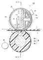
- FIG. 16 is a schematic view of the construction of one example of fixing apparatus adopting the electromagnetic induction film heating fixing method which has increased the fixing efficiency by concentrating the alternating magnetic flux distribution of the excitation coils on the fixing nip portion.
- reference numeral 10 denotes a cylindrical fixing film, as a rotary body, including electromagnetic induction heat generating layers (conductive material layer, magnetic material layer, resistor layer).
- Reference numeral 16 denotes a gutter-shaped film guide member of which cross section is almost semicircular, and the cylindrical fixing film 10 is loose-fit on the outside of this film guide member 16 .
- Reference numeral 15 denotes a magnetic field generating means placed on the inside of the film guide member 16 , which consists of excitation coils 18 and an E-shaped magnetic core (core material) 17 .
- Reference numeral 30 denotes an elastic pressurizing roller, which forms a fixing nip portion N having a predetermined width in combination with the bottom of the film guide member 16 with a predetermined pressure contacting force while nipping the fixing film 10 at the fixing nip portion and allowing the same to mutually come in pressure contact with the elastic pressurizing roller and the bottom of the film guide member.
- the magnetic core 17 of the above magnetic filed generating means 15 is placed in such a manner as to correspond to the fixing nip portion N.
- the pressurizing roller 30 is rotatively driven by a driving means M in the counterclockwise direction shown by an arrow.
- torque acts on the fixing film 10 by the friction force generated between the above pressurizing roller 30 and the external surface of the fixing film 10 ; consequently, the above fixing film 10 is rotated around the periphery of the film guide member 16 at a peripheral speed almost corresponding to that of the pressurizing roller 30 in the clockwise direction shown by an arrow with its internal surface closely touching and sliding on the bottom of the film guide member 16 at the fixing nip portion N (pressuring roller drive fixing method).
- the film guide member 16 serves to pressurize the fixing nip portion N, support the excitation coils 18 and the magnetic core 17 , as a magnetic field generating means 15 , support the fixing film 10 , and stabilize the conveyance of the above film 10 during the rotation thereof.
- This film guide member 16 is an insulating member which does not interfere with magnetic flux's passing and a material is used for it which can resist heavy loads.
- the excitation coils 18 generate alternating magnetic flux with alternating current supplied from an excitation circuit not shown in the figure.
- the alternating magnetic flux distributes intensively at the fixing nip portion N due to the E-shaped magnetic core 17 placed in such a manner as to correspond to the position of the fixing nip portion N and generates an eddy current in the electromagnetic induction heat generating layers of the fixing film 10 at the fixing nip portion N.
- This eddy current generates Joule heat due to the resistivity of the electromagnetic induction heat generating layers.
- the electromagnetic induction heat generation of the fixing film 10 occurs intensively at the fixing nip portion N where alternating magnetic flux is allowed to distribute intensively, the fixing nip portion N is thereby heated at a high efficiency.
- the temperature of the fixing nip portion N is controlled to keep the portion at a fixed temperature by controlling the current supply to the excitation coils 18 with a temperature control system including a temperature detecting means not shown in the figure.
- the pressurizing roller 30 is rotatively driven, and with the rotational motion of the pressurizing roller, the cylindrical fixing film 10 starts to rotate around the periphery of the film guide member 16 , the electromagnetic induction heat generation is caused in the fixing film 10 by the feed from the excitation circuit to the excitation coils 18 as described above, and the fixing nip portion N is heated to a fixed temperature.
- a recording material P which is conveyed from the portion of an image forming means not shown in the figure and has an unfixed toner image t formed thereon, is introduced between the fixing film 10 and the pressurizing roller 30 at the fixing nip portion N with the image side facing up, that is, with the image side facing the surface of the fixing film.
- the image side closely touches the external surface of the fixing film 10 , and the recording material P is conveyed together with the fixing film 10 through the fixing nip portion N while being nipped between the fixing film 10 and the pressurizing roller 30 .
- the recording material P is heated due to the electromagnetic induction heat generation of the fixing film 10 , and the unfixed toner image t is heat fixed on the recording material P.
- the recording material P having passed through the fixing nip portion N is separated from the external surface of the rotating fixing film 10 and conveyed to be discharged.
- Toners for use in the full color image forming process which adopts, for example, electophotographic process are required to exhibit excellent melting and color mixing characteristics when applying heat thereto, and preferably those having sharp melting characteristics, that is, those having a low softening point and a low melt viscosity are used.
- Such highly sharp melting color toners have a strong affinity for a fixing roller or a fixing film, and they are apt to offset on the fixing roller or the fixing film during the fixing operation.
- the double-side copy which forms images on both sides of a recording material and reduces the consumption of paper, are increasing day by day.
- an image forming apparatus is constructed in such a manner that it includes a fixing apparatus adopting the heater type film heating fixing method or the electromagnetic induction film heating fixing method, like a) or b) described above, and the toner having a releasing agent contained its binder which contains a coloring material ingredient is applied thereto.
- the glossiness of the images is not very high and has a moderate gloss value; accordingly, it is necessary not to reduce the melt viscosity of the toner described above very much, but to keep it moderately viscous.
- an object of the present invention is to provide an image forming apparatus which starts up quickly and is capable of forming satisfactory images.
- Another object of the present invention is to provide an image forming apparatus including an unfixed toner image forming means for forming unfixed toner images and a fixing means for fixing on a recording material the unfixed toner images formed by the unfixed toner image forming means, in which the fixing means includes a film, first and second back up members which sandwich the film therebetween and are in pressure contact with each other to form a nip portion, and a heating means for increasing the temperature of the film, nips and conveys the recording material, bearing the unfixed toner image between the film and the second back up member at the nip portion, and fixes the unfixed toner image on the recording material, the toner of the unfixed toner image contains a releasing agent in a binder which contains a coloring material ingredient and have a melt index value of 0.5 g or more and 100 g or less in accordance with the Melt Index measuring method, and the average pressure at the nip portion is 5.9 ⁇ 10 4 Pa or more and 24.5 ⁇ 10 4 Pa or less.
- Still another object of the present invention is to provide an image forming apparatus including an unfixed toner image forming means for forming unfixed toner images and a fixing means for fixing on a recording material the unfixed toner images formed by the unfixed toner image forming means,
- the fixing means includes a fixing member, a back up member in contact with the fixing member, and a magnetic flux generating means for generating magnetic flux
- an eddy is generated in the fixing member by a magnetic flux from the magnetic flux generating means and the fixing means generates heat
- the recording material bearing the unfixed toner image is nipped and conveyed at the contact portion between the fixing member and the back up member, thereby the unfixed toner image is fixed on the recording material
- the toner of the unfixed toner image contains a releasing agent in a binder which contains a coloring material ingredient and have a melt index value of 0.5 g or more and 100 g or less in accordance with a Melt Index measuring method
- the average surface pressure at the nip portion is 5.
- FIG. 1 is a view showing a color image forming apparatus in accordance with one embodiment of the present invention
- FIGS. 2A and 2B are views illustrating shape factors of toners SF 1 and SF 2 , respectively;
- FIG. 3 is a cross-sectional view of a polymerized toner
- FIG. 4 is a cross-sectional side elevation of a fixing apparatus having been applied to an image forming apparatus in accordance with one embodiment of the present invention
- FIG. 5 is a front view of the apparatus shown in FIG. 4;
- FIG. 6 is a front vertical sectional view of the apparatus shown in FIG. 4;
- FIG. 7 is a perspective view of a magnetic field generating means
- FIG. 8 is a view showing the state in which alternating magnetic flux is generated
- FIG. 9 is a safety circuit diagram
- FIGS. 10A and 10B are views showing the layer construction of fixing films
- FIG. 11 is a graphical representation showing the relationship between depth of heat generating layer and intensity of electromagnetic wave
- FIG. 12 is a view showing the state in which a toner image is wrapped with the releasing layer of a fixing film
- FIG. 13 is a cross-sectional side elevation of another fixing apparatus
- FIG. 14 is a cross-sectional side elevation of still another fixing apparatus
- FIG. 15 is a view showing the layer construction of the fixing film shown in FIG. 14;
- FIG. 16 is a cross-sectional side elevation of a fixing apparatus of a prior art.
- FIG. 17 is a view showing blistering portion of a fixed toner image.
- FIG. 1 there is shown a schematic view of the construction of one example of color image forming apparatus embodying the present invention.
- This embodiment is a color laser printer.
- Reference numeral 101 denotes a photosensitive drum (image bearing body) consisting of an organic photosensitive body or an amorphous silicon photosensitive body, which is rotatively driven at a fixed process speed (peripheral speed) in the counterclockwise direction shown by an arrow.
- the surface of the photosensitive drum 101 having been subjected to charging processing is then subjected to scanning exposure processing by a laser beam 103 output from a laser optical box (laser scanner) 110 for the object image information.
- the laser optical box 110 outputs a laser beam 103 having been modulated (on/off) corresponding to time series electric digital pixel signals for the object image information generated from an image signal generating apparatus, such as an image reader, not shown in the figure, so as to form an electrostatic latent image corresponding to the object image information having been subjected to scanning exposure on the photosensitive drum 101 .
- Reference numeral 109 denotes a mirror for deflecting the laser beam 103 output from the laser optical box 110 toward the exposure position of the photosensitive drum 101 .
- a first color separation component image for example, a yellow component image is subjected to scanning exposure as well as latent image formation, and the formed latent image is developed as a yellow toner image by the operation of a yellow developing device 104 Y of four-color developing apparatus 104 .
- the yellow toner image is transferred to the surface of an intermediate transfer drum 105 at a primary transfer portion T 1 which is a contact portion (or proximate portion) of the photosensitive drum 101 with the intermediate transfer drum 105 .
- the surface of the photosensitive drum 101 is cleaned by removing residues, such as the residual transferring toner, adhering thereto with a cleaner 107 after the completion of transferring the toner image to the surface of the intermediate transfer drum 105 .
- a process cycle of charge, scanning exposure, development, primary transfer and cleaning, as described above, is executed in sequence for a second color separation component image (for example, a magenta component image, a magenta developing device 104 M operates), a third color separation component image (for example, a cyan component image, a cyan developing device 104 C operates) and a fourth color separation component image (for example, a black component image, a black developing device 104 BK operates) of the object full color image, and the four color toner images of yellow, magenta, cyan and black are transferred to the surface of the intermediate transfer drum 105 in such a manner as to be superimposed so as to form a color toner image corresponding to the object full color image.
- a second color separation component image for example, a magenta component image, a magenta developing device 104 M operates
- a third color separation component image for example, a cyan component image, a cyan developing device 104 C operates
- a fourth color separation component image for example, a
- the intermediate transfer drum 105 consists of a metal drum with a medium-resistant elastic layer and a high-resistant surface layer provided thereon and is rotatively driven at almost the same speed as the photosensitive drum 101 in the clockwise direction shown by an arrow in state where it is in contact with or proximate to the photosensitive drum 101 .
- a toner image on the side of the photosensitive drum 101 is transferred to the surface of the intermediate transfer drum 105 by applying a bias potential to the metal drum of the intermediate transfer drum 105 to produce a potential difference between the two drums.
- the above color toner image formed on the surface of the intermediate transfer drum 105 is then transferred at a secondary transfer portion T 2 , which is a contact and nip portion of the above intermediate transfer drum 105 and a transfer roller 106 , to the surface of a recording material (hereinafter referred to as transferring material or paper) P sent from a paper feeder portion not shown in the figure to the secondary transfer portion T 2 with a prescribed timing.
- the transfer roller 106 serves to transfer the composite color toner image on the intermediate transfer drum 105 side to the transfer material P side in sequence and collectively by supplying electric charge having a polarity opposite to that of the toners to the back side of the transfer material P.
- the photosensitive drum 101 , the charging apparatus 102 , the developing apparatus 104 , the intermediate transfer drum 105 , the transfer roller 106 , the laser scanner 110 , etc. constitute an unfixed toner image forming means.
- the transfer material P having passed through the secondary transfer portion T 2 is separated from the surface of the intermediate transfer drum 105 and introduced into a fixing apparatus (image heating apparatus) 100 , where the unfixed toner image is subjected to heat fixing processing, and discharged to feeder output tray, not shown in the figure, out of the apparatus.
- a fixing apparatus image heating apparatus
- the intermediate transfer drum 105 is cleaned by removing the residues, such as the residual transferring toners and paper dust, adhering thereto with a cleaner 108 after the completion of transferring the color toner image to the transferring material P.
- the cleaner 108 is held out of contact with the intermediate transfer drum 105 , but it is held in contact with the same during the process of executing the secondary transfer of the color toner image from the intermediate transfer drum 105 to the transfer material P.
- the transfer roller 106 is also held out of contact with the intermediate transfer drum 105 , but it is held in contact with the same via the transfer material P during the process of executing the secondary transfer of the color toner image from the intermediate transfer drum 105 to the transfer material P.
- the apparatus in accordance with this embodiment can call a monochromatic printing mode, that is, a black and white printing mode as well as a double-side printing mode into execution.
- the transfer material P having come out of the fixing apparatus 100 with its first side having been subjected to image printing is sent again to the secondary transfer portion T 2 via a circulating conveying mechanism not shown in the figure, in which it is reversed front side back so that its second side is subjected to toner image transfer, and is introduced again into the fixing apparatus 100 so that the toner image on the second side is subjected to fixing processing, thereby a double-side print is output.
- the toners used in a color image forming apparatus of the present invention contain wax, as a releasing agent, in their binder which contains a coloring material ingredient and their melt viscosity are set at a MI value (melt index value) in the range of 0.5 g to 100 g in accordance with the Melt Index measuring method, as described above. Now the toners will be described.
- non-magnetic single-component fine particle toners which contain a binder resin, a coloring agent, a charge control agent and a material with a low softening point.
- Binder resins in common use for color toners can be used, and they include, for example, styrene-based copolymers such as styrene-polyester and styrene-butyl acrylate copolymers; polyester resins; and epoxy resins.
- Coloring agents in common use for color toners can be used, and those for use in a yellow toner include, for example, benzine yellow pigments, phorone yellow, insoluble acetoacetic anilide azo pigments, monoazo dye, and azo methine coloring material.
- Coloring agents for use in a magenta toner include, for example, phosphotungstomolybdic acid lake which is a xanthene magenta dye, 2,9-dimethylquinacridone, insoluble naphthol azo pigments, anthraquinone dyes, coloring material consisting of xanthene dyes and organic carboxylic acid, and thioindigo.
- Coloring agents for use in a cyan toner include, for example, copper phthalocyanine pigments.
- Charge control agents in common use for color toners can be used, and negative charge control agents include, for example, metal complexes of alkylsalicylic acid, metal complexes of dicarboxylic acid, and polycyclic metal salts of salicylic acid.
- Positive charge control agents include, for example, quaternary ammonium salts, derivatives of benzothiazole, derivatives of guanamine, dibutyltin oxide, and other nitrogen-containing compounds.
- Low softening point materials include, for example, paraffin wax, polyolefin wax, microcrystalline wax, polymethylene wax such as Fischer-Tropsch wax, amide wax, higher fatty acids, long-chain alcohols, ester wax, and the derivatives, such as graft and block compounds, thereof.
- the content of low softening point material is preferably 5 to 30% by weight per 100% by weight toner.
- the toners are preferably polymerized toners obtained by the polymerization method which produces toner particles by polymerizing polymeric monomer compositions containing polymeric monomers, coloring agents, charge control agents and low softening point materials, and more preferably polymerized toners obtained by polymerizing polymeric monomer compositions in a liquid medium, for the polymerized toners thus obtained can be spherical.
- Particularly suspension polymerized toners obtained by the suspension polymerization of polymeric monomer compositions in a water-based medium are preferably used, because the toner particles are allowed to contain wax as a low softening point material in the water-based medium using the difference in polarity among the ingredients contained in the polymeric monomer compositions.
- non-magnetic single-component fine particle polymerized toners of which shape factor SF 1 is 100 to 140, preferably 100 to 120, shape factor SF 2 is 100 to 120, weight average particle diameter is 5 to 7 ⁇ m, and shape is substantially spherical.
- shape factor SF 1 is a value indicating the percentage of the roundness of spherical matter, which is obtained by dividing the square of the maximum length MXLNG of the elliptical figure formed by projecting the spherical matter on a two-dimensional plane by the area AREA of the figure and multiplyng the result by 100 ⁇ /4, as shown in FIG. 2 A.
- shape factor SF 1 is defined by the following equation:
- SF 1 The larger the value of SF 1 becomes, the more indefinite the shape of the spherical matter becomes. If the value SF 1 is too large, the spherical matter loses its properties accompanying its spherical shape, the performance of field cleaning may be weakened.
- shape factor SF 2 is a value indicating the percentage of the irregularities of matter, which is obtained by dividing the square of the peripheral length PERI of the figure formed by projecting the matter on a two-dimensional plane by the area AREA of the figure and multiplying the result by 100/4 ⁇ , as shown in FIG. 2 B.
- shape factor SF 2 is defined by the following equation:
- toners becomes infinitely like spherical shape, transfer efficiency increases.
- the reason may be that the surface energy of each individual toner becomes low, the flow property of the toners is increased, the adsorptivity (mirroring force) of the toners on the photosensitive drum decreases, accordingly the toners become susceptible to transfer field.
- the particle size distribution of toners can be measured by, for example, the following method. It can be measured using Coulter Counter TA-II or Coulter Multi-sizer (manufactured by Coulter, Inc.). As an electrolysis solution, 1% NaCl aqueous solution is prepared using the first grade sodium chloride. For example, ISOTONR-II (manufactured by Coulter Scientific Japan) may be usable.
- the process of measuring is as follows. First, a surfactant as a dispersing agent, preferably 0.1 to 5 ml of alkylbenzensufonate is added to 100 to 150 ml of the above electrolysis solution, then 2 to 20 mg of measuring sample is added. The electrolysis solution with the sample suspended therein is subjected to dispersion processing with an ultrasonic disperser for about 1 to 3 minutes, then the volume and number of the toner 2 ⁇ m or more in diameter are measured with the above measuring apparatus using 100 ⁇ m aperture, so as to calculate the volume distribution and the number distribution. Weight average particle diameter (D 4 ) can be obtained on the basis of the weight calculated from the volume distribution of the toners (a representative value of each channel is used as the representative value for each channel).
- a surfactant as a dispersing agent preferably 0.1 to 5 ml of alkylbenzensufonate is added to 100 to 150 ml of the above electrolysis solution, then 2 to 20 mg of measuring sample is added.
- channels used are 13 channels of, for example, 2.00 to less than 2.52 ⁇ m, 2.52 to less than 3.17 ⁇ m, 3.17 to less than 4.00 ⁇ m, 4.00 to less than 5.04 ⁇ m, 5.04 to less than 6.35 ⁇ m, 6.35 to less than 8.00 ⁇ m, 8.00 to less than 10.08 ⁇ m, 10.08 to less than 12.70 ⁇ m, 12.70 to less than 16.00 ⁇ m, 16.00 to less than 20.20 ⁇ m, 20.20 to less than 25.40 ⁇ m, 25.40 to less than 32.00 ⁇ m, and 32.00 to less than 40.30 ⁇ m.
- FIG. 3 is a schematic view in section showing one embodiment of the above polymerized toner particle.
- the shape of the polymerized toner 90 is spherical.
- the toner particle has a core 93 /shell 92 structure, and the main ingredient of the core portion 93 of the core/shell structure is a low softening point material.
- the low softening point material has a melting point of 40 to 120° C.
- a polymerized toner can be usable which consists of the core 93 containing ester wax, which is a low softening point material, as a main ingredient, the shell portion 92 of styrene-butyl acrylate resin layer, and the surface layer 91 of styrene-polyester.
- lubricant powders such as Teflon, zinc stearate, and polyvinylidene fluoride powders
- abrasives such as cerium oxide, silicon carbide and strontium titanate powders
- flow property imparting agents such as silica, titanium oxide and aluminium oxide powders, and the same powders having been subjected to silane coupling agent and/or silicone oil treatment;
- conductivity imparting agents such as carbon black, zinc oxide and tin oxide powders
- development improvers such as organic and inorganic fine particles with opposite polarity to the toner can also be used within the limit of not substantially affecting the toner.
- One example of methods of producing a polymerized toner is as follows.
- a releasing agent, a coloring agent, a charge control agent, a polymerization initiator and other additives are added to and uniformly dissolved or dispersed in a polymeric monomer with a mixing machine such as homogenizer and ultrasonic disperser, so as to obtain a monomer composition, then the monomer composition is dispersed in a water phase containing a dispersion stabilizer with a disperser such as homomixer. At the stage in which the droplets of the monomer composition have a desired toner particle size, the granulation is stopped. After this, the liquid mixture should be agitated only to a degree that the particle state of the monomer composition can be maintained by the action of the dispersion stabilizer and the particles can be prevented from settling.
- the polymerization is performed at 40° C. or higher, generally at a set temperature of 50 to 90° C.
- the temperature may be raised in the latter half of the polymerization reaction so as to control the molecular weight distribution, in addition, part of water-based medium may be removed by distillation in the latter half of the reaction or after the reaction so as to remove unreacted polymeric monomer and by-product.
- the produced toner particles are collected through cleaning and filtration and dried.
- the suspension polymerization method generally and preferably 300 to 3000 parts by weight of water is used as a dispersion medium per 100 parts by weight of monomer composition.
- the toner is allowed to have the melting viscosity of a MI value of 0.5 g to 100 g in accordance with the Melt Index measuring method (a larger MI value means a lower viscosity), images of good visibility, which are satisfactory in terms of offset during the fixing operation and of which glossiness is not too high, can be obtained all for documents, graphics and photos.
- the above MI value was measured with Semiautomatic 2-A Melt Indexer manufactured by Tokyo Seiki under the following conditions: 2 mm orifice, 5 kg load, heat chamber at 125° C., and for 10 minutes.
- MI value is more than 100 g, the glossiness of images increases, and moreover, with the increase in MI value, offsets during the fixing operation at high temperatures become worse. If the above MI value is less than 0.5 g, toners are hard to fix.
- a fixing apparatus 100 is an apparatus adopting the electromagnetic induction film heating fixing method.
- FIG. 4 is a schematic view in section showing the main part of the fixing apparatus 100
- FIG. 5 a front view showing the main part of the same
- FIG. 6 a front vertical sectional view of the main part of the same.
- the apparatus 100 of this embodiment adopts the pressurizing roller driving method as well as the electromagnetic induction film heating fixing method and uses a cylindrical electromagnetic induction heat generating film (cylindrical rotational body) as the fixing member, like the fixing apparatus shown in FIG. 16 .
- a cylindrical electromagnetic induction heat generating film cylindrical rotational body
- the same constituents and portions as those of the apparatus of FIG. 16 are denoted by the same reference numerals and the description thereof shall be omitted.
- a magnetic field generating means (magnetic flux generating means) 15 consists of magnetic cores 17 a , 17 b and 17 c and excitation coils 18 .
- the magnetic cores 17 a , 17 b and 17 c are highly permeable members, and as the materials, those used for the cores of transformers, such as ferrite and permalloy, are preferably used, and more preferably used is ferrite of which loss is small even at 100 kHz or more.
- An excitation circuit 27 is connected to feeding portions 18 a , 18 b of the excitation coils 18 (FIG. 7 ). This excitation circuit 27 is allowed to generate high frequency of 20 kHz to 500 kHz with a switching power supply.
- the excitation coil 18 generates alternating flux by the supply of alternating current from the excitation circuit 27 .
- Reference numerals 16 a and 16 b denote gutter-shaped film guide members of which cross section is almost semicircular. They constitute an almost cylindrical body with their open sides facing each other and a fixing film 10 , which is a cylindrical electromagnetic induction heat generating film, is loose fitted on the outside thereof.
- the above film guide member 16 a holds the magnetic cores 17 a , 17 b and 17 c and excitation coils 18 , as a magnetic field generating means 15 .
- a highly heat conductive member 40 is placed on the film guide member 16 a on the side of a fixing nip portion N facing a pressuring roller 30 and inside the fixing film 10 and functions as a back up member for backing up the inside of the fixing film.
- the highly heat conductive member 40 is placed outside the magnetic field generated by the excitation coils 18 and magnetic cores 17 a , 17 b and 17 c , as a magnetic field generating means, so that it should not be affected by the magnetic field.
- the highly heat conductive member 40 is placed in such a place as is separated from the excitation coil 18 by a magnetic core 17 c , that is, outside the magnetic path generated by the excitation coil 18 , so that the highly heat conductive member 40 is not affected by the magnetic field.
- Reference numeral 22 denotes a transverse rigid pressurizing stay placed in such a manner as to come in contact with the opposite side of the portion of the highly heat conductive member 40 which faces the nip portion N and with the internal plane portion of the film guide member 16 b.
- Reference numeral 19 denotes an insulating member for insulating the rigid pressurizing stay 22 from the magnetic cores 17 a , 17 b , 17 c and the excitation coils 18 .
- Flange members 23 a , 23 b are fitted on both right and left end portions of the assembly of the film guide members 16 a , 16 b . They are rotatably attached while being fixed at the above right and left position and serve to regulate the skew movement of the fixing film 10 longitudinally along the film members by receiving the end portions of the fixing film during the rotation thereof.
- a pressurizing roller 30 as a pressurizing member which is another back up member, consists of a core bar 30 a , a heat-resistant elastic material layer 30 b of silicone rubber, fluororubber, fluororesin, etc. which is formed in the form of a roller coaxially around the above core bar in such a manner as to coat the same, and a releasing layer 30 c as a surface layer, which is a fluororesin layer (about 10 ⁇ m to 100 ⁇ m thick) of PFA, PTFE, FEP, etc. and it is placed in such a manner that both end portions of its core bar 30 a is freely rotatably held with a bearing between the side plates of a chassis of the apparatus not shown in the figure.
- a press-down force is applied to the rigid pressurizing stay 22 by placing springs 25 a , 25 b in a compressed state between both end portions of the rigid pressurizing stay 22 and spring receiving members 29 a , 29 b on the chassis of the apparatus, respectively.
- This allows the bottom surface of the portion, which corresponds to the nip portion N, of the highly heat conductive member 40 and the top surface of the pressurizing roller 30 to come in press contact with each other via the fixing film 10 , so as to form the fixing nip portion N with a predetermined width.
- the hardness of the pressurizing roller 30 is too high. Desirably the hardness of the pressurizing roller 30 ranges between the lower limit of about 45 degrees (Asker C hardness measured from the surface layer of the pressurizing roller, 1 kg load), in terms of mechanical strength, and the upper limit of 75 degrees, in terms of ensuring a certain nip.
- the pressurizing roller 30 is rotatively driven by a driving means M in the counterclockwise direction shown by an arrow.
- torque acts on the fixing film 10 by the friction force generated between the above pressurizing roller 30 and the external surface of the fixing film 10 , consequently, the above fixing film 10 is rotated around the periphery of the film guide members 16 a , 16 b at a peripheral speed almost corresponding to that of the pressurizing roller 30 in the clockwise direction shown by an arrow with its internal surface sliding on the bottom surface of the highly heat conductive member 40 at the fixing nip portion N.
- a lubricant such as heat-resistant grease is applied between the bottom surface of the highly heat conductive member 40 and the internal surface of the fixing film 10 at the fixing nip portion N so as to reduce the friction force produced by the mutual sliding between the bottom surface of the highly heat conductive member 40 and the internal surface of the fixing film 10 at the fixing nip portion N.
- the bottom surface of the highly heat conductive member 40 may be coated with a lubricating member 41 .
- a lubricant or lubricating member prevents the deterioration of durability of the fixing film 10 which may occur when the fixing film 10 is scraped with highly heat conductive member 40 having poor surface slidability due to its material, for example aluminum, or due to the simplification of the finish machining.
- the highly heat conductive member 40 is effective in making the longitudinal temperature distribution uniform; for example, when passing small size paper, as a transferring material (recording material) P, through the fixing apparatus, the quantity of heat at the non-paper-passing portion of the fixing film 10 is transferred to the highly heat conductive member 40 , and due to the longitudinal heat transfer at the highly heat conductive member 40 , the quantity of heat at the non-paper-passing portion is transferred to the small size paper passing portion. This also produces an effect on decreasing the power consumption during the small size paper passing.
- convex rib portions 16 e are formed and spaced longitudinally at fixed intervals on the peripheral surface of the film guide member 16 a , thereby reducing the contact and slide resistance between the periphery surface of the film guide member 16 a and the internal surface of the fixing film 10 , so as to decrease the rotation load of the fixing film 10 .
- Such convex rib portions 16 e can also be formed and provided on the film guide member 16 b.
- FIG. 8 is a schematic view showing the state where alternating magnetic flux is generated. Magnetic flux C shows part of the alternating magnetic flux generated.
- the alternating magnetic flux C introduced to the magnetic cores 17 a , 17 b , 17 c induces an eddy current in the electromagnetic induction heat generating layer 1 of the fixing film 10 between the two magnetic cores 17 a and 17 b and between the two magnetic cores 17 a and 17 c .
- This eddy current produces Joule heat (eddy current loss) in the electromagnetic induction heat generating layer 1 due to the resistivity thereof.
- the quantity of generated heat Q depends on the density of the magnetic flux passing through the electromagnetic induction heat generating layer 1 and its distribution is shown by the graphical representation of FIG. 8 .
- the heat generating area H is defined as area in which the quantity of generated heat is Q/e or more where Q is the maximum generated heat. This area means an area in which the required quantity of generated heat is obtained.
- the temperature of the fixing nip portion N is controlled by controlling the current supply to the excitation coils 18 with a temperature controlling system including a temperature detecting means 26 (FIG. 4) so as to keep the portion at a predetermined temperature.
- the temperature detecting means 26 is a temperature sensor such as thermister for detecting the temperature of the fixing film 10 , and in this embodiment the temperature of the fixing nip portion N is controlled based on the temperature information of the fixing film 10 measured with this temperature sensor 26 .
- the electromagnetic induction heat generation is caused in the fixing film 10 in such a manner as described above by the feeding from the excitation circuit 27 to the excitation coils 18 , and the fixing nip portion N is heated to a fixed temperature and the temperature is being controlled, a transferring material P, which is conveyed from the portion of an image forming means and has an unfixed toner image t formed thereon, is introduced between the fixing film 10 and the pressurizing roller 30 at the fixing nip portion N with the image side facing up, that is, with the image side facing the surface of the fixing film.
- the image side closely touches the external surface of the fixing film 10 , thus the transferring material is conveyed together with the fixing film 10 through the fixing nip portion N while being nipped between the fixing film 10 and the pressurizing roller 30 .
- the transferring material P is heated due to the electromagnetic induction heat generation of the fixing film 10 , and the unfixed toner image t is heat fixed on the transferring material P.
- the transferring material P having passed through the fixing nip portion N is separated from the external surface of the fixing film 10 and conveyed to be discharged.
- the heat fixed toner image on the transferring material P is cooled to become a permanent fixed image.
- thermoswitch 50 as a temperature detecting element is placed in the position facing the heat generating area H (FIG. 8) of the fixing film 10 in order to break feed to the excitation coils 18 when crush occurs.
- FIG. 9 is a diagram of the safety circuit used in this embodiment.
- the safety circuit is constructed as follows: the thermoswitch 50 as a temperature detecting element is in connection with 24V DC source and a relay switch 51 in series, and when the thermoswitch 50 is turned off, the feed to the relay switch 51 is quickly broken and the relay switch 51 operates, then the feed to the excitation circuit 27 is quickly broken, the feed to the excitation coils 18 is thereby broken.
- the OFF operation temperature of the thermoswitch 50 was set at 220° C.
- thermoswitch 50 was placed in such a manner as to face the heat generating area H of the fixing film 10 and be out of contact with the external surface of the fixing film 10 .
- the spacing between the thermoswitch 50 and the fixing film 10 was about 2 mm. With this spacing, the fixing film 10 is never scraped by the contact with the thermoswitch 50 , and the deterioration of the fixed image after long duration can be prevented.
- thermoswitch 50 is provided for the heat generating area H in which a large quantity of heat is generated; therefore, once the thermoswitch 50 detects 220° C., it is turned off and the relay switch 51 breaks the feed to the excitation coils 18 .
- heat generation of the fixing film 10 can be stopped without igniting paper, because the ignition point of paper is about 400° C.
- thermoswitch 50 In addition to the thermoswitch 50 , a thermal fuse can be used.
- an oil application mechanism for preventing offsets was not provided for the fixing apparatus, because toners containing a low softening point material were used as the toner t.
- the excitation coils 18 were formed by using a bundle of more than one copper small-gage wires (wire bundle), each of which was subjected to insulating coating, as a conductor (electric wire) constituting a coil (wire coil) and winding the same into more than one turns of coil.
- the excitation coils 18 were formed of 10 turns of the above coil.
- a heat resistant insulting coating should be used taking into account the heat transfer caused by the heat generation of the fixing film 10 .
- coatings of amide-imide and polyimide should be used.
- An external pressure may be applied to the excitation coils 18 so as to improve its density.
- the excitation coils 18 were shaped in such a manner as to fit the curved surface of the heat generating layer 1 of the fixing film 10 , as shown in FIGS. 4 and 8.
- the spacing between the heat generating layer 1 of the fixing film 10 and the excitation coils 18 was set for about 2 mm.
- the materials for the film guide members (excitation coil holding members) 16 a , 16 b are excellent in insulating properties and highly heat-resistant.
- the materials such as phenolic resin, fluororesine, polyimide resin, polyamide resin, polyamide-imide resin, PEEK resin, PES resin, PPS resin, PFA resin, PTFE resin, FEP resin, and LCP resin.
- the spacing between the heat generating layer 1 of the fixing film 10 and the excitation coils 18 should not necessarily be constant as long as the spacing is within 5 mm.
- FIG. 10A is a schematic view showing the layer construction of the fixing film 10 in accordance with this embodiment.
- the fixing film 10 of this embodiment is a composite structure consisting of a heat generating layer 1 , as a base layer of the electromagnetic induction heat generating fixing film 10 , formed of metal film etc., an elastic layer 2 stacked on the external surface of the above heat generating layer 1 , and a releasing layer 3 stacked on the external surface of the above elastic layer 2 .
- primer layers may be provided between the above two layers respectively.
- the heat generating layer 1 is provided on the inner surface side and the releasing layer 3 on the outer surface side.
- alternating magnetic flux induces an eddy current in the heat generating layer 1 , thereby the heat generating layer 1 generates heat.
- the generated heat heats the fixing film 10 via the elastic layer 2 and the releasing layer 3 , thereby the transferring material P, as a material to be heated, passed through the above fixing nip portion N is heated, resulting in heat fixing of toner images.
- ferromagnetic metals such as nickel, iron, ferromagnetic SUS, and nickel-cobalt alloy are used for the heat generating layer 1 .
- Non-magnetic metals may also be used, however, metals of high flux absorptivity such as nickel, iron, ferromagnetic stainless steel, and nickel-cobalt alloy are more preferably used.
- the thickness of the heat generating layer 1 is larger than the skin depth value obtained from the equation shown below and 200 ⁇ m or less.
- the skin depth ⁇ [mm] is expressed by the following equation:
- f [Hz] frequency of the excitation circuit 27
- ⁇ permeability
- ⁇ [ ⁇ m] resistivity
- the skin depth indicates the depth of absorbing electromagnetic waves used in electromagnetic induction. At the portion deeper than the skin depth, the intensity of the electromagnetic waves is 1/e or less, in other words, energy is mostly absorbed before the skin depth is reached (FIG. 11 ).
- the thickness of the heat generating layer 1 is 1 to 100 ⁇ m. If the thickness is less than 1 ⁇ m, most magnetic energy cannot be absorbed and the efficiency decreases.
- the thickness of the heat generating layer 1 is preferably determined to be in the range of 1 to 100 ⁇ m while taking into account the mechanical strength.
- a nickel electrocast product 50 ⁇ m thick was used.
- the elastic layer 2 materials excellent in heat resistance and heat conduction, such as silicone rubber, fluororubber and fuluorosilicone rubber, are used.
- This elastic layer plays an important part in the prevention of the fine mosaic-like image defect known as “pore”, which has been described in the description of the prior arts. Specifically, in the use of the wax-containing toner described above, in order to prevent “pore” from occurring, an effect is needed that the releasing layer 3 as a surface layer of the fixing film 10 reflects the elasticity of the elastic layer 2 and wraps the toner itself (refer to FIG. 12 ).
- the elastic layer 2 is required to be such that its hardness as a simple rubber is 30 degrees or less, more preferably 25 degrees or less in terms of the hardness specified by the JIS-A measurement, that is, by the JIS-K6301 A hardness meter and that its thickness is 50 ⁇ m or more, more preferably 100 ⁇ m or more.
- the thickness of the elastic layer 2 exceeds 500 ⁇ m, the heat resistance of the elastic layer becomes too high, and quick start is hard to realize (almost impossible when the thickness is 1000 ⁇ m or more). Accordingly, the thickness of the elastic layer 2 is desirably 500 ⁇ m or less.
- the heat conductivity ⁇ of the elastic layer 2 is preferably 2.5 ⁇ 10 ⁇ 1 to 8.4 ⁇ 10 ⁇ 1 [W/m/° C.] (6 ⁇ 10 ⁇ 4 to 2 ⁇ 10 ⁇ 3 [cal/cm ⁇ sec ⁇ deg.]).
- the heat conductivity ⁇ is less than 2.5 ⁇ 10 ⁇ 1 [W/m/° C.], the heat resistance becomes high, and the temperature increase becomes slow on the surface layer of the fixing film (the releasing layer 3 ).
- the heat conductivity ⁇ is preferably 2.5 ⁇ 10 ⁇ 1 to 8.4 ⁇ 10 ⁇ 1 [W/m/° C.], more preferably 3.3 ⁇ 10 ⁇ 1 to 6.3 ⁇ 10 ⁇ 1 [W/m/° C.] (8 ⁇ 10 ⁇ 4 to 1.5 ⁇ 10 ⁇ 3 [cal/cm ⁇ sec ⁇ deg.]).
- silicone rubber with hardness, as a simple rubber hardness, of 10 degrees (JIS-A), heat conductivity of 4.2 ⁇ 10 ⁇ 1 [W/m/° C.] (1 ⁇ 10 ⁇ 3 [cal/cm ⁇ sec ⁇ deg.]) and thickness of 300 ⁇ m.
- the releasing layer 3 materials excellent in releasing tendency and heat resistance such as fluororesin, silicone resin, fluorosilicone rubber, fluororubber, silicone rubber, PFA, PTFE and FEP can be selected.
- the releasing layer 3 may be a tube layer or resin coating layer of these fluorine-based resins.
- the thickness of the releasing layer 3 is required to be 100 ⁇ m or less at the maximum, more preferably 80 ⁇ m or less. If the thickness of the releasing layer 3 is more than 100 ⁇ m, the effect that the layer wraps the toner decreases, resulting in the occurrence of “pore” on a solid image.
- the maximum thickness value of the releasing layer 3 is required to be small. After the intensive examination of the present applicants, it was found that the thickness of the releasing layer 3 is required to be 1 ⁇ 3 or less of that of the elastic layer 2 at the maximum. When the thickness of the releasing layer 3 was more than 1 ⁇ 3 of that of the elastic layer 2 , the surface layer of the fixing film 10 did not fully reflect the elasticity of the elastic layer 2 .
- the thickness of the releasing layer 3 is required to be 5 ⁇ m or more at the minimum, more preferably 10 ⁇ m or more.
- a PFA tube 30 ⁇ m thick was used as the releasing layer 3 .
- the relationships between the thickness of the above elastic layer 2 and that of the releasing layer 3 described so far can be put together to form the following viewpoint: preferably, 50 ⁇ m ⁇ t1 ⁇ 500 ⁇ m, 5 ⁇ m ⁇ t 2 ⁇ 100 ⁇ m, t 1 ⁇ 3 ⁇ t 2 where t 1 is the thickness of the elastic layer 2 and t 2 is the thickness of the releasing layer 3 .
- an insulating layer 4 may be provided on the surface on the film guide member side of the heat generating layer 1 (opposite to the elastic layer 2 side of the heat generating layer 1 ).
- insulating layer 4 preferably used are materials of heat-resistant resins such as fluororesin, polyimide resin, polyamide resin, polyamideimide resin, PEEK resin, PES resin, PPS resin, PFA resin, PTFE resin and FEP resin.
- heat-resistant resins such as fluororesin, polyimide resin, polyamide resin, polyamideimide resin, PEEK resin, PES resin, PPS resin, PFA resin, PTFE resin and FEP resin.
- the thickness of the insulating layer 4 is preferably 10 to 1000 ⁇ m. If the thickness of the insulating layer 4 is less than 10 ⁇ m, insulating effect is not produced. In addition, its durability becomes insufficient. On the other hand, if the thickness of the insulating layer 4 exceeds 1000 ⁇ m, the spacing between the magnetic cores 17 a, 17 b, 17 c as well as the excitation coils 18 and the heat generating layer 1 becomes large, and magnetic flux is not fully absorbed in the heat generating layer 1 .
- the insulating layer 4 can insulate the heat generated in the heat generating layer 1 so that it should not be transferred to the inside of the fixing film 10 , the efficiency of supplying heat to the transferring material P side is high, compared with the fixing film without an insulating layer 4 . As a result, power consumption can be reduced.
- the apparatus constructed as described above In order to form a full color image and fix the same on a transferring material with the apparatus constructed as described above, it is necessary to ensure a sufficient heating time in the fixing nip portion N.
- the nip at least 6 mm or more, preferably 7 mm or more in size is required to ensure.
- Table-1 shows the state of the fixing defect occurrence at various nip sizes and various average surface pressures at the nip portion.
- the parameters of the nip size and surface pressure can be changed to predetermined values depending on the hardness or diameter of the pressurizing roller 30 , the total contact pressure between the fixing film 10 and the pressurizing roller 30 , the width and shape of the pressurizing rigid stay, and the hardness or thickness of the elastic layer 2 of the fixing film 10 .
- the evaluation is the minimum limit for practical use when the nip size is 6 mm or more and is good when the nip size is 7 mm or more, but on the other hand, for the blistering, the evaluation is poor at a surface pressure of 29.4 ⁇ 10 4 Pa (3.0 kgf/cm 2 ), is the minimum line for practical at a surface pressure of 24.5 ⁇ 10 4 Pa (2.5 kgf/cm 2 ) or less, and is good at a surface pressure of 19.6 ⁇ 10 4 Pa (2.0 kgf/cm 2 ) or less. This indicates that even in the nip area where satisfactory fixing characteristics can be obtained, if the surface pressure is high, blistering occurs, thereby resulting in poor images.
- a nip about 8 mm in size was formed under the following conditions: preparing a pressurizing roller 30 that has a length of 250 mm, a diameter of 25 mm, an elastic layer 30 b having a thickness of 4 mm and a PFA tube 30 C of 50 ⁇ m thick covering the above elastic layer, selecting the product hardness of the pressurizing roller 30 measured on the PFA tube to be 56 degrees (Asker C hardness, 9.8 N (1 kg) load), selecting the width of the pressurizing rigid stay in the fixing film 10 to be 10 mm, and bringing the fixing film 10 in pressure contact with the pressurizing roller 30 at a total pressure of 196.1 N (20 kg). With this nip, satisfactory fixed images were obtained which were free from both “pore” and blistering.
- the glossiness value tends to decrease, on the other hand, when the surface pressure is raised, the glossiness value tends to increase, for the same reason as described in terms of the transmission of OHP. Therefore, if the surface pressure is controlled within the range of the above described favorable surface pressure 5.9 ⁇ 10 4 Pa to 24.5 ⁇ 10 4 Pa (0.6 kgf/cm 2 to 2.5 kgf/cm 2 ), the glossiness of images can be controlled to some extent. Further if the upper limit of the surface pressure is specified, the deterioration of the film can be prevented.
- FIG. 13 is a cross-sectional side elevation of the fixing apparatus 100 in accordance with this embodiment.
- the fixing apparatus can be constructed in such a manner as to rig a belt guide 16 , a driving roller 31 and a tension roller 32 with an electromagnetic induction heat generating fixing belt 10 in the form of a endless belt in a tightly stretched manner, form a fixing nip portion N by allowing the bottom surface of the belt guide 16 and a pressurizing roller 30 , as a pressurizing member, to be in pressure contact with each other via the fixing belt 10 , and rotatively drive the fixing belt 10 by the driving roller 31 .
- the pressurizing roller 30 is a driven rotary roller.
- Such a construction enables the reduction of torque when driving the fixing belt 10 , which makes it easy to drive the belt 10 even if the width of the nip N is made large.
- the surface pressure in the nip cannot be increased in order to prevent the blistering problem described above; therefore, the nip width N must be enlarged, so as to gain time for fixing in the nip.
- the fixing belt 10 is directly driven with the driving roller 31 , as shown in FIG. 13, the belt 10 can be driven without any trouble even if the nip width N is made large to some extent.
- the similar effect described in terms of the previous embodiment was obtained by selecting the surface pressures similar to those of the previous embodiment.
- the fixing belt 10 was able to be driven easily.
- the fixing apparatus in accordance with this embodiment is the apparatus adopting a film heating fixing method which uses a ceramics heater as a heating body.
- FIG. 14 is a schematic view in section of the fixing apparatus 100 in accordance with this embodiment.
- Reference numerals 16 c denotes a heat-resistant/heat-insulating gutter-shaped film guide member of which cross-section is almost semicircular and numeral 12 denotes a ceramic heater, as a heating body, which is fitted into a groove portion cut and provided almost in the middle portion of the bottom surface of the film guide 16 c longitudinally along the same, so as to be fixed in and supported by the film guide.
- Reference numeral 11 denotes a cylindrical or endless heat-resistant fixing film. This fixing film 11 is loose fitted on the film guide 16 c.
- Reference numeral 30 denotes a pressurizing member, an elastic pressurizing roller in this embodiment, consisting of a core bar 30 a and an elastic layer 30 b of silicone rubber and the like provided on the core bar 30 a so as to decrease the hardness, the pressurizing member being placed in such a manner as to allow both end portions of its core bar 30 a to be supported with respective bearings in a freely rotatable manner between the side plates of the front side and rear side chassis not shown in the figure.
- a fluororesin layer 30 c of, for example, PTFE, PFA or FEP may be provided on its periphery so as to improve its surface characteristics.
- a pressurizing means for forming a fixing nip N and a holding means for holding the end portions of the fixing film are constructed in the same manner as the embodiment previously described and the description thereof shall be omitted.
- a pressurizing roller 30 As a pressurizing roller 30 , the same pressurizing roller as those used in the previously described embodiments can be used.
- the pressurizing roller 30 is rotatively driven in the counterclockwise direction shown by an arrow by a driving means M.
- torque acts on the fixing film 11 by the friction force generated between the above pressurizing roller 30 and the external surface of the fixing film 11 ; consequently, the above fixing film 11 is rotated around the periphery of the film guide member 16 c at a peripheral speed almost corresponding to that of the pressurizing roller 30 in the clockwise direction shown by an arrow with its internal surface closely touching and sliding on the bottom surface of the ceramic heater 12 at the fixing nip portion N (pressuring roller drive fixing method).
- a lubricating member 40 is placed on the bottom surface of the ceramic heater 12 at the fixing nip portion N and a lubricant such as heat-resistant grease is applied between the lubricating member 40 and the internal surface of the fixing film 11 so as to reduce the friction force produced by the mutual sliding between the bottom surface of the ceramic heater 12 and the internal surface of the fixing film 11 at the fixing nip portion N.
- the pressurizing roller 30 is allowed to start rotating based on the print start signal and the ceramic heater 12 starts to be heated-up.
- a transferring material P as a material to be heated, which has a toner image t formed thereon is introduced between the fixing film 11 and the pressurizing roller 30 at the fixing nip portion N with the image side facing the surface of the fixing film 11 .
- the transfer material P closely touches the bottom surface of the ceramic heater 12 via the fixing film 11 at the fixing nip portion N and passing through the same together with the fixing film 11 .
- the heat of the ceramic heater 12 is transferred thereto via the fixing film 11 , and the toner image t is heat fixed on the surface of the transferring material P.
- the transferring material P having passed through the fixing nip portion N is separated from the surface of the fixing film 11 and conveyed.
- the fixing film 11 consists of a base layer 201 , an elastic layer 202 and a releasing layer 203 , as shown in FIG. 15 .
- heat-resistant films of, for example, polyimide, polyimide amide, PEEK, PES, PPS, PTFE, PFA or FEP of which thickness is 100 ⁇ m or less, preferably 50 ⁇ m or less and 20 ⁇ m or more can be used.
- a cylindrical polyimide film 25 mm in diameter was used.
- silicone rubber was used of which rubber hardness is 10 degrees (JIS-A), heat conductivity is 4.18605 ⁇ 10 ⁇ 1 W/m ⁇ ° C. (1 ⁇ 10 ⁇ 3 [cal/cm ⁇ sec ⁇ deg]) and thickness is 200 ⁇ m.
- a PFA coat layer 20 ⁇ m was used for the releasing layer 203 .
- the same PFA tube as described in terms of the previous embodiment may be used for the releasing layer 203 .
- the PFA coat is excellent in that it can be made thin, and from the standpoint of the material, it wraps toner more effectively than the PFA tube.
- the PFA tube is superior to the PFA coat, accordingly, they can be used properly depending on the situation.
- the ceramic heater 12 as a heating body is a transverse linear heating body with a low heat capacity which extends in the direction orthogonal to the direction in which the fixing film 11 and the transferring material P move.
- the ceramic heater 12 basically consists of a heater substrate 12 a formed of, for example, aluminum nitride; a heat generating layer 12 b provided on the surface of the heater substrate 12 a along its longitudinal direction, for example, a heat generating layer 12 b provided by coating an electrically resistant material, such as Ag/Pd (silver/palladium), about 10 ⁇ m long and 1 to 5 mm wide by the screen printing; and a protective layer 12 c of, for example, glass and fluororesin provided on the heat generating layer 12 b.
- an electrically resistant material such as Ag/Pd (silver/palladium)
- the heat generating layer 12 b of the above ceramic heater 12 generates heat when electric current is applied between both ends thereof and the heater 12 is rapidly heated.
- the temperature of the heater 12 is controlled in such a manner as to detect temperature of the heater with a temperature sensor not shown in the figure, control current application to the heat generating layer 12 b with a controlling circuit not shown in the figure so as to keep the heater at a prescribed temperature.
- the ceramic heater 12 described above is fitted into the groove portion cut and provided almost in the middle of the bottom surface of the film guide 16 c longitudinally along the guide with its protective layer 12 c facing up, so as to be fixed in and supported by the film guide 16 c .
- the surface of the sliding member 40 of the heater 12 and the internal surface of the fixing film 11 come in contact with each other and slide.
- wax-containing toners have been described taking the case where the spherical toners produced by the polymerization method are used; however, the present invention is also effective when using the non-spherical or almost spherical wax-containing toners produced by the pulverizing method.
- the fixing apparatus adopting the electromagnetic heat generating fixing method in accordance with the embodiment described above has its heat generating portion close to the nip and is particularly excellent in response to heat; therefore, it can be suitably used not only for printing apparatus using a single photosensitive body, as shown in FIG. 1, but also for, for example, inline-type printers which are capable of full color printing in a batch using 4 photosensitive bodies, and quick start and oilless fixing can be realized of which characteristics never deteriorate even when performing high-speed continuous printing.
- Further film fixing members 10 , 11 are not limited to those in the cylindrical or endless belt form. They may be rolls of continuous web-like members having ends which are let out and allowed to run.
- a film was used for a fixing member, however, a rigid roller can also be used for the same.
- a full color fixing system requiring no oil application means can be constructed, and at the same time, images free from defects, such as blistering and “su (pores)”, and having glossiness not too high, that is, having a satisfactory gloss value are obtained by using toners which contain wax in their binder and have a MI value in the range of 0.5 to 100 g and by pressing a recording material against the fixing member under a nip surface pressure of 5.9 Pa to 24.5 Pa (0.6 kgf/cm 2 to 2.5 kgf/cm 2 ) by a pressurizing means.
- heating the above fixing member using the electromagnetic induction method or the direct heating method enables the construction of an energy-saving-type fixing system which is capable of quick starting.
- the present invention makes it possible to use fixing apparatus adopting the film heating fixing method or electromagnetic induction heating fixing method in the fixing operation of full color toner images in an oilless manner without causing any troubles, as a result, a full color fixing system requiring no releasing agent (oil) application, ensuring satisfactory fixing performance, and capable of quick starting is constructed.
Landscapes
- Physics & Mathematics (AREA)
- General Physics & Mathematics (AREA)
- Spectroscopy & Molecular Physics (AREA)
- Chemical & Material Sciences (AREA)
- Inorganic Chemistry (AREA)
- Fixing For Electrophotography (AREA)
- Developing Agents For Electrophotography (AREA)
- Color Electrophotography (AREA)
Applications Claiming Priority (2)
| Application Number | Priority Date | Filing Date | Title |
|---|---|---|---|
| JP2000028966A JP2001215767A (ja) | 2000-02-07 | 2000-02-07 | カラー画像形成装置 |
| JP2000-028966 | 2000-02-07 |
Publications (2)
| Publication Number | Publication Date |
|---|---|
| US20010022909A1 US20010022909A1 (en) | 2001-09-20 |
| US6505027B2 true US6505027B2 (en) | 2003-01-07 |
Family
ID=18554297
Family Applications (1)
| Application Number | Title | Priority Date | Filing Date |
|---|---|---|---|
| US09/775,582 Expired - Lifetime US6505027B2 (en) | 2000-02-07 | 2001-02-05 | Image forming apparatus with toner having releasing agent in a binder |
Country Status (2)
| Country | Link |
|---|---|
| US (1) | US6505027B2 (enExample) |
| JP (1) | JP2001215767A (enExample) |
Cited By (18)
| Publication number | Priority date | Publication date | Assignee | Title |
|---|---|---|---|---|
| US20030063916A1 (en) * | 2001-09-28 | 2003-04-03 | Hidetoshi Katayanagi | Image forming apparatus having a fixing device |
| US20030170054A1 (en) * | 2002-02-05 | 2003-09-11 | Canon Kabushiki Kaisha | Image heating apparatus |
| US20040004071A1 (en) * | 2002-04-30 | 2004-01-08 | Takayuki Ogasawara | Induction heating roller unit, fixing device and image forming apparatus |
| US6721530B2 (en) * | 2001-03-28 | 2004-04-13 | Hewlett-Packard Development Company, L.P. | Fusing system having electromagnetic heating |
| US6898410B2 (en) * | 2001-11-30 | 2005-05-24 | Hewlett-Packard Development Company, L.P. | Low thermal mass heated fuser |
| US20050169655A1 (en) * | 2004-02-04 | 2005-08-04 | Canon Kabushiki Kaisha | Image forming apparatus and its control method |
| US20050169659A1 (en) * | 2004-02-04 | 2005-08-04 | Canon Kabushiki Kaisha | Image forming apparatus and its control method |
| US20050169658A1 (en) * | 2004-02-04 | 2005-08-04 | Canon Kabushiki Kaisha | Image forming apparatus |
| US20050207770A1 (en) * | 2004-02-03 | 2005-09-22 | Canon Kabushiki Kaisha | Image heating apparatus having heater for externally heating fixing roller |
| US20050252912A1 (en) * | 2002-09-25 | 2005-11-17 | Canon Kabushiki Kaisha | Image forming apparatus and fixing apparatus |
| US20050286939A1 (en) * | 2004-06-29 | 2005-12-29 | Samsung Electronics Co., Ltd. | Device for fusing toner on print medium |
| US7277651B2 (en) | 2004-02-04 | 2007-10-02 | Canon Kabushiki Kaisha | Image forming apparatus and control method with power controlled in accordance with remaining amount of rechargeable battery power |
| US20080080910A1 (en) * | 2006-09-28 | 2008-04-03 | Brother Kogyo Kabushiki Kaisha | Fixing Device and Image-Forming Apparatus |
| CN100492215C (zh) * | 2004-06-04 | 2009-05-27 | 夏普株式会社 | 加热辊、加热装置以及图像形成装置 |
| US20100247183A1 (en) * | 2009-03-27 | 2010-09-30 | Shigehiko Haseba | Fixing device and image forming apparatus |
| US20120093550A1 (en) * | 2010-10-14 | 2012-04-19 | Canon Kabushiki Kaisha | Fixing device |
| US9244409B2 (en) | 2013-09-30 | 2016-01-26 | Brother Kogyo Kabushiki Kaisha | Fixing device having nip member with elastic layer |
| US12172862B2 (en) | 2021-11-22 | 2024-12-24 | Canon Kabushiki Kaisha | Sheet feeding apparatus and image forming apparatus |
Families Citing this family (21)
| Publication number | Priority date | Publication date | Assignee | Title |
|---|---|---|---|---|
| JP2001342319A (ja) * | 2000-06-01 | 2001-12-14 | Matsushita Electric Ind Co Ltd | フッ素ゴム組成物、定着部材、定着方法、及び定着装置 |
| JP2002072752A (ja) * | 2000-09-01 | 2002-03-12 | Canon Inc | 定着装置及びこの定着装置を備える画像形成装置 |
| JP5013641B2 (ja) * | 2001-09-21 | 2012-08-29 | キヤノン株式会社 | 像加熱装置及び画像形成装置 |
| JP3880359B2 (ja) * | 2001-10-05 | 2007-02-14 | 株式会社巴川製紙所 | オイルレス定着用フルカラートナー |
| JP2003195666A (ja) * | 2001-12-21 | 2003-07-09 | Ricoh Co Ltd | ベルト及び定着ベルト又はそのベルトからなる定着ベルトを具備する定着装置並びにその定着装置を具備する画像形成装置 |
| US6583393B1 (en) * | 2002-01-22 | 2003-06-24 | Kabushiki Kaisha Toshiba | Induction heating fixing device with an extended pressure contact area for use with magnetic toner |
| US7024923B2 (en) | 2002-03-22 | 2006-04-11 | Ricoh Company, Ltd. | Method for evaluating fixing member and fixing belt and thermal fixing roller |
| US7113717B2 (en) * | 2004-03-30 | 2006-09-26 | Xerox Corporation | Closed loop control of nip pressure in a fuser system |
| JP2006039023A (ja) * | 2004-07-23 | 2006-02-09 | Ricoh Co Ltd | 静電荷像現像用トナー、製造方法、画像形成装置及びプロセスカートリッジ |
| JP4818826B2 (ja) * | 2006-06-19 | 2011-11-16 | 株式会社リコー | 定着装置および画像形成装置 |
| JP2008107770A (ja) * | 2006-09-29 | 2008-05-08 | Ricoh Printing Systems Ltd | 定着装置およびそれを用いた画像形成装置 |
| EP1927902B1 (en) * | 2006-11-28 | 2015-10-14 | Ricoh Company, Ltd. | Fixing Device and Image forming Apparatus Including the Fixing Device |
| JP5240554B2 (ja) | 2008-06-03 | 2013-07-17 | 株式会社リコー | トナーキット、画像形成方法、画像形成装置 |
| JP5438978B2 (ja) * | 2009-01-21 | 2014-03-12 | 京セラドキュメントソリューションズ株式会社 | 定着装置及び画像形成装置 |
| JP2012013761A (ja) * | 2010-06-29 | 2012-01-19 | Canon Inc | 画像形成装置 |
| JP5273138B2 (ja) * | 2010-12-24 | 2013-08-28 | ブラザー工業株式会社 | 定着装置 |
| JP5273137B2 (ja) | 2010-12-24 | 2013-08-28 | ブラザー工業株式会社 | 定着装置 |
| JP5321577B2 (ja) | 2010-12-24 | 2013-10-23 | ブラザー工業株式会社 | 定着装置 |
| JP5316529B2 (ja) | 2010-12-24 | 2013-10-16 | ブラザー工業株式会社 | 定着装置 |
| JP5879859B2 (ja) * | 2011-09-20 | 2016-03-08 | ブラザー工業株式会社 | 定着装置 |
| JP2014056147A (ja) * | 2012-09-13 | 2014-03-27 | Ricoh Co Ltd | 定着装置および画像形成装置 |
Citations (12)
| Publication number | Priority date | Publication date | Assignee | Title |
|---|---|---|---|---|
| JPS51109739A (ja) | 1975-03-20 | 1976-09-28 | Suwa Seikosha Kk | Hyojisochi |
| JPS63313182A (ja) | 1987-06-16 | 1988-12-21 | Canon Inc | 像加熱装置 |
| JPH02157878A (ja) | 1988-12-12 | 1990-06-18 | Canon Inc | 画像加熱定着装置 |
| JPH0444075A (ja) | 1990-06-11 | 1992-02-13 | Canon Inc | 像加熱装置 |
| JPH04204980A (ja) | 1990-11-30 | 1992-07-27 | Canon Inc | 像加熱装置 |
| US5331385A (en) | 1990-05-15 | 1994-07-19 | Canon Kabushiki Kaisha | Fixing rotatable member having conductive parting layer and fixing apparatus using same |
| US5543904A (en) | 1994-04-28 | 1996-08-06 | Canon Kabushiki Kaisha | Fixating device |
| US5745833A (en) * | 1995-02-15 | 1998-04-28 | Canon Kabushiki Kaisha | Image heating device |
| US6005594A (en) | 1990-03-26 | 1999-12-21 | Canon Kabushiki Kaisha | Fixing apparatus having a fixing roller with a non-adhesive surface layer |
| US6021303A (en) * | 1998-05-15 | 2000-02-01 | Matsushita Electric Industrial Co., Ltd. | Image heating device and image forming device using the same |
| US6057074A (en) * | 1998-02-10 | 2000-05-02 | Fuji Xerox Co., Ltd. | Method of forming an image and a recording medium used therefor |
| US6131010A (en) | 1996-11-15 | 2000-10-10 | Canon Kabushiki Kaisha | Rotatable member having elastic layer and fixing apparatus having said rotatable member |
-
2000
- 2000-02-07 JP JP2000028966A patent/JP2001215767A/ja active Pending
-
2001
- 2001-02-05 US US09/775,582 patent/US6505027B2/en not_active Expired - Lifetime
Patent Citations (12)
| Publication number | Priority date | Publication date | Assignee | Title |
|---|---|---|---|---|
| JPS51109739A (ja) | 1975-03-20 | 1976-09-28 | Suwa Seikosha Kk | Hyojisochi |
| JPS63313182A (ja) | 1987-06-16 | 1988-12-21 | Canon Inc | 像加熱装置 |
| JPH02157878A (ja) | 1988-12-12 | 1990-06-18 | Canon Inc | 画像加熱定着装置 |
| US6005594A (en) | 1990-03-26 | 1999-12-21 | Canon Kabushiki Kaisha | Fixing apparatus having a fixing roller with a non-adhesive surface layer |
| US5331385A (en) | 1990-05-15 | 1994-07-19 | Canon Kabushiki Kaisha | Fixing rotatable member having conductive parting layer and fixing apparatus using same |
| JPH0444075A (ja) | 1990-06-11 | 1992-02-13 | Canon Inc | 像加熱装置 |
| JPH04204980A (ja) | 1990-11-30 | 1992-07-27 | Canon Inc | 像加熱装置 |
| US5543904A (en) | 1994-04-28 | 1996-08-06 | Canon Kabushiki Kaisha | Fixating device |
| US5745833A (en) * | 1995-02-15 | 1998-04-28 | Canon Kabushiki Kaisha | Image heating device |
| US6131010A (en) | 1996-11-15 | 2000-10-10 | Canon Kabushiki Kaisha | Rotatable member having elastic layer and fixing apparatus having said rotatable member |
| US6057074A (en) * | 1998-02-10 | 2000-05-02 | Fuji Xerox Co., Ltd. | Method of forming an image and a recording medium used therefor |
| US6021303A (en) * | 1998-05-15 | 2000-02-01 | Matsushita Electric Industrial Co., Ltd. | Image heating device and image forming device using the same |
Cited By (29)
| Publication number | Priority date | Publication date | Assignee | Title |
|---|---|---|---|---|
| US6721530B2 (en) * | 2001-03-28 | 2004-04-13 | Hewlett-Packard Development Company, L.P. | Fusing system having electromagnetic heating |
| US7079802B2 (en) * | 2001-09-28 | 2006-07-18 | Konica Corporation | Fixing device with specific surface roughness |
| US20030063916A1 (en) * | 2001-09-28 | 2003-04-03 | Hidetoshi Katayanagi | Image forming apparatus having a fixing device |
| US6898410B2 (en) * | 2001-11-30 | 2005-05-24 | Hewlett-Packard Development Company, L.P. | Low thermal mass heated fuser |
| US20030170054A1 (en) * | 2002-02-05 | 2003-09-11 | Canon Kabushiki Kaisha | Image heating apparatus |
| US6947699B2 (en) | 2002-02-05 | 2005-09-20 | Canon Kabushiki Kaisha | Image heating apparatus with projection extending in longitudinal direction of supporting member |
| US20040004071A1 (en) * | 2002-04-30 | 2004-01-08 | Takayuki Ogasawara | Induction heating roller unit, fixing device and image forming apparatus |
| US6818871B2 (en) * | 2002-04-30 | 2004-11-16 | Harison Toshiba Lighting Corp. | Induction heating roller unit, fixing device and image forming apparatus |
| US7196296B2 (en) * | 2002-09-25 | 2007-03-27 | Canon Kabushiki Kaisha | Image forming apparatus and fixing apparatus |
| US20050252912A1 (en) * | 2002-09-25 | 2005-11-17 | Canon Kabushiki Kaisha | Image forming apparatus and fixing apparatus |
| US7190914B2 (en) | 2004-02-03 | 2007-03-13 | Canon Kabushiki Kaisha | Image heating apparatus having heater for externally heating fixing roller |
| US20050207770A1 (en) * | 2004-02-03 | 2005-09-22 | Canon Kabushiki Kaisha | Image heating apparatus having heater for externally heating fixing roller |
| US20050169659A1 (en) * | 2004-02-04 | 2005-08-04 | Canon Kabushiki Kaisha | Image forming apparatus and its control method |
| US7277651B2 (en) | 2004-02-04 | 2007-10-02 | Canon Kabushiki Kaisha | Image forming apparatus and control method with power controlled in accordance with remaining amount of rechargeable battery power |
| US20050169658A1 (en) * | 2004-02-04 | 2005-08-04 | Canon Kabushiki Kaisha | Image forming apparatus |
| US20050169655A1 (en) * | 2004-02-04 | 2005-08-04 | Canon Kabushiki Kaisha | Image forming apparatus and its control method |
| US7254353B2 (en) | 2004-02-04 | 2007-08-07 | Canon Kabushiki Kaisha | Image forming apparatus and method of controlling commercial power supply to fusing means |
| US7257341B2 (en) | 2004-02-04 | 2007-08-14 | Canon Kabushiki Kaisha | Image forming apparatus with power supply control for fusing control circuit |
| US7260337B2 (en) | 2004-02-04 | 2007-08-21 | Canon Kabushiki Kaisha | Image forming apparatus with control of commercial and battery power supplies to fusing device |
| CN100492215C (zh) * | 2004-06-04 | 2009-05-27 | 夏普株式会社 | 加热辊、加热装置以及图像形成装置 |
| US20050286939A1 (en) * | 2004-06-29 | 2005-12-29 | Samsung Electronics Co., Ltd. | Device for fusing toner on print medium |
| US20080080910A1 (en) * | 2006-09-28 | 2008-04-03 | Brother Kogyo Kabushiki Kaisha | Fixing Device and Image-Forming Apparatus |
| US8412072B2 (en) | 2006-09-28 | 2013-04-02 | Brother Kogyo Kabushiki Kaisha | Fixing device and image-forming apparatus |
| US20100247183A1 (en) * | 2009-03-27 | 2010-09-30 | Shigehiko Haseba | Fixing device and image forming apparatus |
| US7965970B2 (en) * | 2009-03-27 | 2011-06-21 | Fuji Xerox Co., Ltd. | Fixing device and image forming apparatus |
| US20120093550A1 (en) * | 2010-10-14 | 2012-04-19 | Canon Kabushiki Kaisha | Fixing device |
| US8509668B2 (en) * | 2010-10-14 | 2013-08-13 | Canon Kabushiki Kaisha | Fixing device |
| US9244409B2 (en) | 2013-09-30 | 2016-01-26 | Brother Kogyo Kabushiki Kaisha | Fixing device having nip member with elastic layer |
| US12172862B2 (en) | 2021-11-22 | 2024-12-24 | Canon Kabushiki Kaisha | Sheet feeding apparatus and image forming apparatus |
Also Published As
| Publication number | Publication date |
|---|---|
| US20010022909A1 (en) | 2001-09-20 |
| JP2001215767A (ja) | 2001-08-10 |
Similar Documents
| Publication | Publication Date | Title |
|---|---|---|
| US6505027B2 (en) | Image forming apparatus with toner having releasing agent in a binder | |
| CN101458485B (zh) | 定影装置以及图像形成装置 | |
| US6456819B1 (en) | Image heating apparatus | |
| US8509668B2 (en) | Fixing device | |
| KR100548838B1 (ko) | 건식 토너, 건식 토너의 제조방법 및 화상형성방법 | |
| JP4474056B2 (ja) | 加熱装置 | |
| JP2006047960A (ja) | 定着装置及びこれを用いた画像形成装置 | |
| EP1333340A2 (en) | Induction heating type image heating apparatus | |
| JP4181879B2 (ja) | トナー及び画像形成方法 | |
| JP2002025759A (ja) | 加熱装置および画像形成装置 | |
| JP2001341231A (ja) | 積層フィルム、定着フィルムおよびそれを用いた像加熱装置 | |
| JP2006301106A (ja) | 加熱装置 | |
| JP2003207931A (ja) | 非磁性トナー及び定着方法 | |
| JP4266658B2 (ja) | トナー及び画像形成方法 | |
| JP2006084564A (ja) | 画像形成方法 | |
| JP2012083632A (ja) | 定着装置 | |
| JP2002134264A (ja) | 加熱装置および画像形成装置 | |
| JP2003195663A (ja) | 画像形成装置 | |
| JP2002258514A (ja) | トナー、カラートナー及び画像形成方法 | |
| JP2001343788A (ja) | カラートナー及び画像形成方法 | |
| JP2001006868A (ja) | 加熱部材、加熱装置および画像形成装置 | |
| JP2002091055A (ja) | トナー及び画像形成方法 | |
| JP3945171B2 (ja) | 静電潜像現像用黒色トナーおよびその製造方法、並びに、画像形成方法および画像形成装置 | |
| JP2001027858A (ja) | 加熱装置、像加熱装置および画像形成装置 | |
| JPH09146392A (ja) | トナー定着フィルム |
Legal Events
| Date | Code | Title | Description |
|---|---|---|---|
| AS | Assignment |
Owner name: CANON KABUSHIKI KAISHA, JAPAN Free format text: ASSIGNMENT OF ASSIGNORS INTEREST;ASSIGNORS:TAKEUCHI, AKIHIKO;SUZUKI, MASAHIRO;REEL/FRAME:011794/0743 Effective date: 20010302 |
|
| STCF | Information on status: patent grant |
Free format text: PATENTED CASE |
|
| CC | Certificate of correction | ||
| FPAY | Fee payment |
Year of fee payment: 4 |
|
| FPAY | Fee payment |
Year of fee payment: 8 |
|
| FPAY | Fee payment |
Year of fee payment: 12 |