US6498598B2 - Imaging device system, control method for the system, imaging device, control device, control method for the imaging device, control method for the control device, and storage medium - Google Patents
Imaging device system, control method for the system, imaging device, control device, control method for the imaging device, control method for the control device, and storage medium Download PDFInfo
- Publication number
- US6498598B2 US6498598B2 US09/356,460 US35646099A US6498598B2 US 6498598 B2 US6498598 B2 US 6498598B2 US 35646099 A US35646099 A US 35646099A US 6498598 B2 US6498598 B2 US 6498598B2
- Authority
- US
- United States
- Prior art keywords
- control
- imaging device
- node
- camera
- control parameter
- Prior art date
- Legal status (The legal status is an assumption and is not a legal conclusion. Google has not performed a legal analysis and makes no representation as to the accuracy of the status listed.)
- Expired - Lifetime
Links
Images


Classifications
-
- H—ELECTRICITY
- H04—ELECTRIC COMMUNICATION TECHNIQUE
- H04L—TRANSMISSION OF DIGITAL INFORMATION, e.g. TELEGRAPHIC COMMUNICATION
- H04L12/00—Data switching networks
- H04L12/28—Data switching networks characterised by path configuration, e.g. LAN [Local Area Networks] or WAN [Wide Area Networks]
- H04L12/40—Bus networks
- H04L12/40052—High-speed IEEE 1394 serial bus
- H04L12/40058—Isochronous transmission
-
- H—ELECTRICITY
- H04—ELECTRIC COMMUNICATION TECHNIQUE
- H04L—TRANSMISSION OF DIGITAL INFORMATION, e.g. TELEGRAPHIC COMMUNICATION
- H04L12/00—Data switching networks
- H04L12/28—Data switching networks characterised by path configuration, e.g. LAN [Local Area Networks] or WAN [Wide Area Networks]
- H04L12/40—Bus networks
- H04L12/40052—High-speed IEEE 1394 serial bus
- H04L12/40117—Interconnection of audio or video/imaging devices
-
- H—ELECTRICITY
- H04—ELECTRIC COMMUNICATION TECHNIQUE
- H04N—PICTORIAL COMMUNICATION, e.g. TELEVISION
- H04N23/00—Cameras or camera modules comprising electronic image sensors; Control thereof
- H04N23/60—Control of cameras or camera modules
- H04N23/63—Control of cameras or camera modules by using electronic viewfinders
- H04N23/631—Graphical user interfaces [GUI] specially adapted for controlling image capture or setting capture parameters
- H04N23/632—Graphical user interfaces [GUI] specially adapted for controlling image capture or setting capture parameters for displaying or modifying preview images prior to image capturing, e.g. variety of image resolutions or capturing parameters
-
- H—ELECTRICITY
- H04—ELECTRIC COMMUNICATION TECHNIQUE
- H04N—PICTORIAL COMMUNICATION, e.g. TELEVISION
- H04N23/00—Cameras or camera modules comprising electronic image sensors; Control thereof
- H04N23/60—Control of cameras or camera modules
- H04N23/65—Control of camera operation in relation to power supply
-
- H—ELECTRICITY
- H04—ELECTRIC COMMUNICATION TECHNIQUE
- H04N—PICTORIAL COMMUNICATION, e.g. TELEVISION
- H04N23/00—Cameras or camera modules comprising electronic image sensors; Control thereof
- H04N23/60—Control of cameras or camera modules
- H04N23/66—Remote control of cameras or camera parts, e.g. by remote control devices
- H04N23/661—Transmitting camera control signals through networks, e.g. control via the Internet
Definitions
- the present invention relates to apparatus and method for outputting a command from outside of a device to change a control method of the device to execute an operation different from that actuated by remote control executed by the device's control unit.
- peripheral devices of a personal computer such as a PC hereinafter
- a PC personal computer
- a hard disk and a printer have been connected to the PC through a universal interface for small computers, e.g., a digital interface (referred to as a digital I/F) such as a SCSI, for data communication.
- a digital I/F digital interface
- SCSI SCSI
- Digital cameras and digital video cameras are also regarded as input means to a PC and are also peripheral devices. Recently, the technology of transferring images (such as still and motion pictures picked up by digital cameras and video cameras) into a PC along with accompanying voice signals, storing the pictures in a hard disk or editing them in the PC, and then color-printing the pictures using a printer has been developed and has gained popularity.
- a connector for connection to a SCSI cable is provided on the back side of the PC.
- Such a connector has a relatively large size, and it is rather troublesome to couple the cable to the connector.
- Digital data communication has been used for mutual communication between a PC and such peripheral devices, and has utilized conventional communication techniques. It is however expected in the future that the types of devices using digital data will increase, and an improvement of I/Fs can improve network communication among many interconnected digital devices including PC peripheral devices to include digital video cameras, digital storage medium playback apparatuses, etc. If so, such network communication will be very convenient for users. On the other hand, since such communication will often transfer an extremely large amount of data, the use of conventional communication techniques will make the network crowded and adversely affect the communication between other devices in the network.
- a method has been proposed to overcome the problems encountered in the conventional digital I/Fs, and to employ a universal digital I/F (e.g., IEEE 1394-1995 High Performance Serial Bus) equipped on each piece of digital equipment in conformity with a unified standard for communication between all the types of digital equipment including PCs and peripheral devices thereof.
- a universal digital I/F e.g., IEEE 1394-1995 High Performance Serial Bus
- the proposed method intends to realize data communication among devices when a PC, a printer and other peripheral devices, a digital camera, a digital VTR, a camcoder, etc. are connected to each other in the form of a network.
- the IEEE 1394 I/F has several remarkable advantages. Because of high-speed serial communication, though described later in detail, a cable is relatively thin and highly flexible, and the connector size is much smaller than the case of using a SCSI cable. Further, a large amount of data such as image information can be transferred at a high speed along with device control data. In other words, communication using the IEEE 1394 I/F is greatly advantageous in that when connecting portable equipment (such as digital cameras and video cameras), the connection work is much less troublesome for users, and image information can be more easily transferred to PCs.
- the IEEE 1394 serial bus will be described below in more detail.
- the IEEE 1394-1995 High Performance Serial Bus
- 1394 serial bus is an interface that has been developed from the above point of view.
- FIG. 7 shows an example of a network system made up by using 1394 serial buses.
- the network system includes devices A, B, C, D, E, F, G and H. Twisted pair cables constituting 1394 serial buses are employed to interconnect between A and B, between A and C, between B and D, between D and E, between C and F, between C and G, between C and H.
- the devices A to H comprise, e.g., a PC, a digital VTR, a DVD player, a digital camera, a hard disk, a monitor, etc.
- the devices can be interconnected in a mixed fashion of a daisy chain system and a node branch system with a high degree of flexibility.
- each device has its own specific ID, and recognizes the IDs of the other devices which constitute a network devices interconnected by the 1394 serial buses.
- 1394 serial buses just by connecting two pieces of digital equipment successively with one 1394 serial bus, one network is constructed by devices each of which has a relay function.
- the entire network has the feature of the 1394 serial buses, i.e., a function of automatically recognizing network devices, their connection status, etc. based on the plug and play function at the time when the bus cables are connected to the devices.
- the bus reset is automatically made to reset the network configuration, and a new network is formed. This function makes it possible to always set and recognize the network configuration from time to time.
- the 1394 serial buses allow data transfer rates of 100/200/400 Mbps. Devices having higher data transfer rates support the lower data transfer rates for compatibility between the devices.
- As data transfer modes there are an asynchronous transfer mode for transferring asynchronous data (referred to as Asynch data hereinafter) such as a control signal, and an isochronous transfer mode for transferring isochronous data (referred to as Iso data hereinafter) such as real-time video data and audio data.
- Asynch data and the Iso data are transmitted in a mixed fashion within each cycle (being usually 125 ⁇ s) with a higher priority given to the Iso data, following transfer of a cycle start packet (CSP) which indicates the start of the cycle.
- CSP cycle start packet
- FIG. 8 shows constituent elements of the 1394 serial bus.
- the 1394 serial bus is of a layered structure in its entirety. As shown in FIG. 8, the core of hardware components is a 1394 serial bus cable. A connector of the cable is connected to a connector port, and a physical layer and a link layer exist as other hardware components at a level higher than the connector port.
- the physical layer executes coding, control related to the connector, etc, and the link layer executes packet transfer, control of cycle time, etc.
- a transaction layer (as one of the firmware components) manages data to be subjected to transfer (transaction), and issues commands such as Read and Write.
- a serial bus management (as the other firmware component) manages connection status of the devices connected to the bus, IDs, and the network configuration.
- An application layer (as a software component) varies depending on the software used.
- the application layer specifies a manner of placing data on the interface, and is specified by a protocol such as an AV protocol.
- the 1394 serial bus is constructed as described above.
- FIG. 9 shows an address space in the 1394 serial bus.
- the devices (nodes) connected to the 1394 serial bus are each given with its own specific 64-bit address, without exceptions.
- the node addresses are stored in a ROM so that each device can always recognize its own and other addresses, and can perform communication with a partner designated.
- the node address is set as follows. The first 10 bits are used for designating the bus number, and the next 6 bits are used for designating the node ID number. The remaining 48 bits represent an address width allocated to the device, and can be used as a specific address space. The last 28 bits represent a specific data area in which information necessary for identifying the device and designating service conditions thereof are stored.
- FIG. 10 shows a section of the 1394 serial bus cable.
- power lines can be disposed in addition to two sets of twisted signal line pairs.
- power can be supplied to, e.g., a device having no power supply, or to a device having a voltage lowered due to a failure.
- a simplified connecting cable may exclude power lines under conditions which restrict devices to which the cable may be connected.
- Power supplied through the power lines is specified to have a voltage of 8 to 40 V and a maximum DC current of 1.5 A.
- FIG. 11 is a chart for explaining a DS-Link coding method of a data transfer format employed for the 1394 serial bus.
- the 1394 serial bus employs a DS-Link (Data/Strobe-Link coding method.
- the DS-Link coding method is suitable for high-speed serial data communication, and requires two signal lines. Of a pair of twisted lines, one line serves to transmit primary data, and the other line serves to transmit a strobe signal.
- a clock can be reproduced by taking the exclusive logical sum of data and strobe.
- the devices (nodes) connected to the bus are each given a specific node ID, and recognized as one of the nodes of a network configuration.
- each node having detected such a change transmits a bus reset signal on the bus, and goes into a mode for recognizing a new network configuration.
- a change of the bias voltage on a 1394 port board is detected by sensing a change of the bias voltage on a 1394 port board.
- the bus reset is started up.
- the bus reset is started up when a hardware change, such as insertion or removal of the cable or an abnormal condition of the network, is detected as described above, or when a command is directly issued to the physical layer under host control in accordance with the protocol.
- data transfer is temporarily suspended upon the start-up of the bus reset, and is held in a standby state during the suspension. After the suspension, data transfer is restarted under a new network configuration.
- the nodes After the bus reset, the nodes start the operation for allocating IDs to themselves to construct a new network configuration. A general sequence from the bus reset to the determination of node IDs will be described below with reference to flowcharts of FIGS. 19, 20 and 21 .
- the flowchart of FIG. 19 shows a sequence of steps executed on the bus from the bus reset until the node IDs are determined to permit start of data transfer.
- step S 101 it is always monitored whether a bus reset occurs in the network. If the bus reset occurs due to, e.g., power-on/off in the node, the processing goes to step S 102 .
- step S 102 parent-child relation is declared between nodes, which are directly connected to each other, for determining the connection status of a new network from the reset state of the network. If parent-child relations are decided between all the nodes in step S 103 , one root is decided in step S 104 . Until parent-child relations are decided between all the nodes, the declaration of parent-child relation in step S 102 is repeated and the root is not decided.
- step S 104 the processing goes to step S 105 in which the node ID setting operation is carried out to allocate IDs to the nodes.
- the node ID setting operation is repeated to set the node IDs in a predetermined node sequence until all the nodes are given their own IDs. If all the nodes are completely given the IDs in step S 106 , this means that the new network configuration has been recognized by all of the nodes.
- step S 107 therefore, the bus comes into a state capable of performing data transfer between the nodes, and the data transfer is started.
- step S 107 the bus is brought again into the mode of monitoring the occurrence of the bus reset in the network. If the bus reset occurs, the node ID setting operation from step S 101 to step S 106 is repeated.
- FIGS. 20 and 21 are flowcharts showing in more detail a process from the bus reset to the determination of the root and a process from the determination of the root to the end of the ID setting, respectively, in the flowchart of FIG. 19 .
- step S 201 If the bus reset occurs in step S 201 , the network configuration is once reset.
- step S 201 It is always monitored in step S 201 whether a bus reset occurs in the network.
- step S 202 a flag indicating that the device is a leaf (node) is set in each such device as a first step of the operation for recognizing the connection status of the reset network.
- step S 203 it is checked how many ports provided in each device itself are connected to other nodes.
- step S 204 The number of ports not yet defined (i.e., for which a parent-child relation is not yet decided) is checked in step S 204 for starting the declaration of parent-child relations depending on the number of ports obtained in step S 204 . Immediately after the bus reset, the number of ports is equal to the number of ports not yet defined. However, the number of ports not yet defined, which is detected in step S 204 , varies as the decision of parent-child relation progresses.
- the node for which parent-child relation can be first declared is limited to only a leaf. Whether the node is a leaf can be recognized by confirming the number of ports checked in step S 203 . In step S 205 , the leaf declares “I am a child and a partner is a parent” for the node to which the leaf is connected, thereby ending the process.
- step S 203 For the node which has been recognized in step S 203 as having a plurality of ports and being a branch, the number of not-yet-defined ports >1 is determined in step S 204 immediately after the bus reset. Accordingly, the processing goes to step S 206 in which a flag indicating a branch is set. Then, in step S 207 , the node waits for accepting “parent” based on the declaration of parent-child relation from the leaf.
- step S 207 For the branch having accepted in step S 207 the declaration of parent-child relation from the leaf, the control flow returns to step S 204 to confirm the number of ports not yet defined. If the number of ports not yet defined is one, this means that the declaration of “I am a child and a partner is a parent” in step S 205 can be made for the node which is connected to the remaining port. For the branch having two or more ports not yet defined as a result of the second or later confirmation in step S 204 , the processing goes to step S 207 again to wait for accepting “parent” based on the declaration of parent-child relation from the leaf or another branch.
- step S 204 if the number of ports not yet defined becomes zero as a result of the confirmation in step S 204 for any one branch or a leaf as an exceptional case (because the leaf has not operated so fast though it can declare “child”), this means that the declaration of parent-child relation is completed for the entire network.
- a flag indicating a root is set in step S 208 . Then, in step S 209 , that node is recognized as a root.
- step S 301 Since flag information indicating a leaf, branch or root is set for each node in the sequence of steps shown in FIG. 20, the nodes are classified in step S 301 based on the flag information.
- the node which can first set an ID is a leaf.
- step S 302 the number N (N is a natural number) of leaves present in the network is set.
- each leaf requests the root to give an ID to the leaf. If there are a plurality of requests, the root carries out arbitration between the requests (operation of selecting one request) in step S 304 .
- step S 305 an ID number is given to one node which has won the arbitration, and a failure in ID setting is provided to the nodes which have been defeated in the arbitration.
- Each leaf which has failed in acquiring ID issues an ID request again in step S 306 , followed by repeating the steps mentioned above.
- step S 307 the leaf which has succeeded in acquiring an ID number broadcasts its own self-ID packet to all the nodes.
- the self-ID packet contains ID information of the node, the number of ports of the node, the number of ports already connected, information indicating whether each port is a parent or a child, information indicating whether the node has an ability allowing the node to serve as a bus manager (if the node has such an ability, a contender bit in the self-ID packet is set to 1, and if the node does not have such an ability, the contender bit is set to 0), etc.
- the ability allowing the node to serve as a bus manager means such an ability that the node can perform the four kinds of bus management set forth below.
- the node can determine whether each of the devices on the network constructed as shown in FIG. 7 is required to be supplied with power through the power lines in the connecting cable, or whether each device is supplied with power independently. Also, the node can manage the time when power is supplied to each device.
- the node can maintain communication speed information of the devices on the network.
- the node can maintain information regarding a tree structure of the network as shown in FIG. 12 .
- the node (which is selected as a bus manager through later-described procedures) performs the bus management in the entire network.
- the node having the ability to serve as a bus manager (i.e., the node broadcasting the self-ID packet with the contender bit set to 1) stores information in the self-ID packet broadcast from each of the remaining nodes, and other information such as communication speeds. When that node is selected as a bus manager, it constructs a speed map and a topology map based on the stored information.
- the ID setting of branches is performed in a like manner to the ID setting of leaves.
- step S 310 the number M (M is a natural number) of branches present in the network is set.
- each branch requests the root to give an ID to the branch.
- the root carries out arbitration between the requests in step S 312 . ID numbers increasing from the last number given to the leaf are allocated to respective branches successively starting from the branch which has first won the arbitration.
- step S 313 the root provides the ID information (or a failure result) to each of the branches having requested IDs.
- Each branch which has failed in acquiring an ID issues an ID request again in step S 314 , followed by repeating the steps mentioned above.
- the node which has not yet acquired ID information is only a root. Therefore, a number next to the largest among the numbers having been already allocated to the other nodes is set as the ID number of the root in step S 318 , and the root broadcasts its own self-ID packet in step S 319 .
- node has the ability to serve as a bus manager. If a plurality of nodes finally have an ability to serve as a bus manager, the node having the largest ID number is selected as the bus manager.
- the root When the root has the ability to serve as the bus manager, the root is selected as the bus manager because its ID number is the largest in the network. When the root does not have the ability to serve as the bus manager, the root which has the second largest ID number (as compared with that of the root and the contender bit in the self-ID packet is set to 1) is selected as the bus manager. Which node has been selected as the bus manager can be ascertained by all the nodes as a matter recognized by all of them because each node broadcasts its own self-ID packet at the time of acquiring the ID number in the process shown in FIG. 21 and each node keeps the information in the self-ID packets broadcast from the other nodes.
- the network shown in FIG. 12 has a hierarchical structure such that the nodes A and C are directly connected to the (root) node B at a level lower than the latter, the node D is directly connected to the node C at a level lower than the latter, and the nodes E and F are directly connected to the node D at a level lower than the latter.
- the procedures for deciding the hierarchical structure, the root node, and the node IDs will be described below.
- parent-child relation After the bus reset, the declaration of parent-child relation is fist made between ports of the nodes, which are directly connected to each other, for recognizing the connection status of each node.
- the parent-child relation means that the parent side lies at a higher level and the child side lies at a lower level in the hierarchical structure.
- the node which has first declared parent-child relation after the bus reset is the node A.
- the declaration of parent-child relation can be started from a node (called a leaf) in which only one port is connected to another node.
- a node can detect by itself that only one port thereof is connected to another node.
- the node Upon detecting the fact, the node recognizes that it is positioned at the end of the network. Then, the parent-child relation is successively decided from the node which has finished the recognizing operation at the earliest timing.
- the port of the node which has declared a parent-child relation (e.g., the node A between A and B) is set to a child, whereas the port of the partner node (the node B) is set to a parent.
- the nodes A and B, the nodes E and D, and the nodes F and D are decided respectively as a child and a parent.
- the declaration process then moves up a rank.
- the declaration of parent-child relation is likewise made toward an upper level node successively from one of nodes having a plurality of ports connected (called a branch) which has earlier accepted the parent-child relation from another node.
- the node D first declares parent-child relation to the node C.
- the nodes D and C are decided respectively as a child and a parent.
- the node C After accepting the declaration of parent-child relation from the node D, the node C declares parent-child relation to the node B which is connected to the other port of the node C. As a result, the nodes C and B are decided respectively as a child and a parent.
- the hierarchical structure shown in FIG. 12 is constructed, and the node B, for which all ports thereof connected to the other nodes have been finally decided as parents, is decided as a root node.
- One network system includes only one root.
- the root node could possibly shift to another node if the node B (having accepted the declaration of a parent-child relation from the node A) declares a parent-child relation to another node at an earlier time.
- any node has the possibility to become the root node depending on the timing at which its declaration of a parent-child relation is transmitted, and a certain node is not always decided as the root node even in the same network configuration.
- the network After deciding the root node, the network enters the mode of deciding node IDs. In this mode, each node provides its own node ID to all of the other nodes (broadcasting function).
- Self-ID information of the node contains the self-node number, information regarding the position at which it is connected, the number of ports possessed by the node, the number of ports connected to other ports, information regarding parent-child relation for each port, etc.
- the procedures for allocating the node ID numbers can be started from one of nodes (leaves) each having only one port connected to another node.
- the node ID numbers 0, 1, 2, . . . are then allocated in sequence to those nodes.
- each node Upon receiving the node ID number, each node broadcasts self-ID information containing the node ID number to all of the other nodes. This permits the other nodes to recognize that the broadcast ID number has been already allocated.
- the mode proceeds to the operation of deciding IDs of branches, and increasing node ID numbers subsequent to the largest number given to the last leaf are allocated to the branches successively.
- each branch upon receiving the node ID number, each branch broadcasts self-ID information in sequence with all of the other nodes. Finally, the root node broadcasts self-ID information. Thus the root always has the largest node ID number.
- node ID numbers are allocated to all the nodes in the entire the hierarchical structure, the network configuration is reconstructed, and the bus initialization is completed.
- the 1394 serial bus constructs such a logical bus type network that each of devices individually connected to the bus relays a signal transferred to it, whereby the same signal is transmitted to all the devices in the network. Accordingly, arbitration is essential for the purpose of avoiding collision between packets. The arbitration enables only one node to transfer a packet at a certain time.
- FIG. 13A illustrates a process of requesting the right of using the bus
- FIG. 13B illustrates a process of permitting/rejecting the use of the bus.
- one or several nodes Upon the start of arbitration, one or several nodes issue requests the right of using the bus toward the corresponding parent nodes.
- the nodes C and F are nodes issuing requests for the right of using the bus.
- the parent node having received the request i.e., the node A in FIG. 13A
- Those requests finally reach the root which performs the arbitration.
- the root node having received the requests for the right of using the bus decides which node is permitted to use the bus.
- the arbitration process can be executed by only the root node, and the node which has won the arbitration is given with the right of using the bus.
- the use of the bus is permitted to the node C, and the node F is rejected from using the bus.
- a DP (Data Prefix) packet is sent to the node which has been rejected in the arbitration, thereby informing the node that the use of the bus has been rejected.
- the request for the right of using the bus, which has been issued from the rejected node is left standing to wait for the next arbitration.
- the node which has won the arbitration and has gained permission for the use of the bus, can start data transfer subsequently.
- the bus When the node starts data transfer, the bus must be in an idle state for enabling the data transfer to start. Whether a preceding data transfer is ended and the bus is in an idle state at present can be recognized by checking the lapse of a predetermined idle time gap length (e.g., a subaction gap) which is uniquely set for each transfer mode. If the subaction gap has lapsed, each node determines that the node itself can start the data transfer.
- a predetermined idle time gap length e.g., a subaction gap
- step S 401 it is determined whether the predetermined gap length corresponding to data to be transferred (such as Asynch data or Iso data) is obtained. Unless the predetermined gap length is obtained, any node cannot request the right of using the bus that is needed for starting the data transfer. Accordingly, each node waits until the predetermined gap length is obtained.
- data to be transferred such as Asynch data or Iso data
- step S 402 it is determined in step S 402 whether there is data to be transferred. If so, the processing goes to step S 403 in which each node issues a request for the right of using the bus to the root for securing the bus to start the data transfer. At this time, a signal representing the request for the right of using the bus is transmitted so as to finally reach the root after being relayed from one to another device in the network, as shown in FIG. 13 . If there is no data to be transferred in step S 402 , the node goes into a standby state.
- step S 404 the root checks the number of nodes requesting the use of the bus in step S 405 . If the number of nodes requesting the use of the bus is equal to one in step S 405 (i.e., if only one node has issued the request for the right of using the bus), the right of using the bus immediately thereafter is granted to that node. If the number of nodes requesting the use of the bus is more than one in step S 405 (i.e., if a plurality of nodes have issued requests for the right of using the bus), the root performs a arbitration process in step S 406 for deciding one node which is allowed to use the bus. The arbitration process is made impartial so that permission is not given to the same node at every time, but the right of using the bus is equally permitted to all the nodes.
- step S 407 the plurality of nodes requesting the use of the bus in step S 406 are classified into one node which has gained the right of using the bus as a result of the arbitration performed by the root, and the other nodes which have been rejected in the arbitration.
- step S 408 the root transmits a permission signal to one node which has gained the right of using the bus as a result of the arbitration, or the node which has gained the right of using the bus without the arbitration because the number of nodes requesting the use of the bus is equal to one in step S 405 .
- the node starts the transfer of data (a packet to be transferred).
- step S 409 the root transmits a DP (Data Prefix) signal indicating a failure in the arbitration to each of the nodes which has been rejected in the arbitration in step S 406 and rejected from using the bus.
- the node having received the DP packet returns to step S 401 , and then waits until the predetermined gap length is obtained, followed by issuing the requests for the right of using the bus to start the data transfer.
- DP Data Prefix
- FIG. 14 shows state transitions over time in the asynchronous transfer mode.
- the first subaction gap in FIG. 14 represents an idle state of the bus.
- the node desiring to start the data transfer determines that the bus is available, following which the arbitration is executed to secure the bus.
- the data transfer is executed in the form of a packet.
- the node having received the data responds to the data transferred to it by sending back an ACK (return code for confirming reception) as a result of the reception after a short gap called the ACK GAP, or by transmitting a response packet, whereupon the packet transfer is completed.
- the ACK comprises information of 4 bits and checksum of 4 bits.
- the ACK includes information indicating whether the destination node of the transmission has succeeded in receiving the data, or whether it is in a busy state or a pending state, and is sent back to the source node at once.
- FIG. 15 shows an example of a packet format for use in the asynchronous transfer mode.
- a packet comprises a data portion, a data CRC for error correction, and a header portion.
- the destination node ID, the source node ID, the length of transferred data, various codes, etc. are written in the header portion as shown in FIG. 15, and then transferred.
- the asynchronous transfer is communication carried out in one-to-one relation from some node to a partner node.
- a packet transferred from the source node is routed to all the nodes in the network, but the node ignores the packet having an address other than belonging to itself. Accordingly, the packet is read by only one destination node.
- isochronous transfer data is transferred in an isochronous manner.
- the isochronous transfer which can be the biggest feature of the 1394 serial bus, is a transfer mode suitable for multimedia such as video data and voice data, particularly, which require real-time transfer.
- the isochronous transfer renders a packet to be transferred from one source node equally to all the other nodes with the broadcasting function.
- FIG. 16 shows state transition over time in the isochronous transfer mode.
- the isochronous transfer is executed with certain time intervals on the bus. This time interval is called an isochronous cycle.
- the time of one isochronous cycle is 125 ⁇ s.
- a cycle start packet indicates the start time of each cycle, and serves to perform time adjustment for each node.
- the cycle start packet is transmitted by a node called a cycle master. After a predetermined idle period (subaction gap) has elapsed subsequent to the end of packet transfer in the preceding cycle, the cycle master transmits the cycle start packet indicating the start of the current cycle.
- the time interval at which the cycle start packet is transmitted is 125 ⁇ s.
- plural types of packets can be separately transferred in one cycle by allocating channel IDs to those packets respectively.
- This enables packets to be transferred in real time between a plurality of nodes at the same time.
- the node on the receiving side takes in data of only the packet assigned with the channel ID that is desired by the node itself.
- the channel ID does not represent the address of the destination of transmission, but merely indicates a logical number (or character) given to each packet data for discrimination. Therefore, when some packet is transmitted, the packet is broadcast so that it is routed from one source node to all of the other nodes.
- arbitration Prior to transmitting a packet in the isochronous transfer mode, arbitration is performed as with the asynchronous transfer mode. However, because the isochronous transfer mode is not a one-to-one communication (unlike the asynchronous transfer mode), there is no ACK (return code for confirming reception) in the isochronous transfer mode.
- an ISO GAP isochronous gap
- an ISO GAP isochronous gap
- FIG. 16 represents an idle period necessary for recognizing that the bus is in an idle state, prior to starting the isochronous transfer.
- the node desiring to start the isochronous transfer determines that the bus is in an idle state, following which an arbitration is conducted before the packet transfer can be executed.
- FIG. 17 shows an example of a packet format for use in the isochronous transfer mode.
- Various packets are separated into channels and each comprises a data portion, a data CRC for error correction, and a header portion.
- the length of transferred data, the channel No., various codes, a header CRC for error correction, etc. are written in the header portion as shown in FIG. 17, and then transferred.
- the isochronous transfer mode has been described above.
- FIG. 18 shows transfer state transitions on the bus over time when the isochronous transfer and the asynchronous transfer are executed in mixed fashion.
- the isochronous transfer is executed in preference to the asynchronous transfer.
- the reason is that after the cycle start packet, the isochronous transfer can be started with a shorter gap length (isochronous gap) than the gap length (subaction gap) of an idle period required for starting the asynchronous transfer. Accordingly, execution of the isochronous transfer is given with higher priority than that of the asynchronous transfer.
- the cycle start packet is transferred from the cycle master to each node at the start of a cycle #m.
- each node Upon receiving the cycle start packet, each node performs time adjustment. After waiting for the predetermined idle period (isochronous gap), the node which is going to execute the isochronous transfer enters arbitration and then starts the packet transfer.
- channels e, s and k are transferred by isochronous transfer in sequence.
- the node which is going to execute the asynchronous transfer determines that it may enter the arbitration.
- the asynchronous transfer can be started only when the subaction gap necessary for starting the asynchronous transfer is obtained during a period from the end of the isochronous transfer to the time (CYCLE SYNCH) at which the next cycle start packet is transferred.
- the operation is not forcibly suspended, and the cycle start packet for the next cycle is transmitted after waiting for the idle period subsequent to the pending transfer.
- the next cycle is contracted from the reference period, i.e., 125 ⁇ s, by an amount corresponding to the extension of the preceding cycle.
- the isochronous cycle can be extended and contracted from the reference period of 125 ⁇ s.
- the asynchronous transfer is always executed in each cycle if necessary. Due to contraction of the cycle time, the asynchronous transfer may be delayed to the next or subsequent cycle.
- each node incorporates a configuration ROM for expressing its own functions.
- FIG. 23 shows a part of the configuration ROM.
- IDs stored in addresses from FFFFF000040C to FFFFF0000410 comprise a vendor ID 2301 of three bytes and chip IDs 2302 , 2303 of five bytes.
- the vendor ID 2301 is an ID acquired by each vendor as a result from applying for the ID from the IEEE, and contains information indicating, e.g., the name of each vendor.
- the chip IDs 2302 , 2303 are allocated at the vendor's discretion, and are set to a unique ID for each node. There is hence no ID that is the same as the unique ID ( 2301 - 2303 ) of each node.
- the above ID ( 2301 - 2303 ) uniquely allocated for each node is called a World Wide Unique ID (referred to a WWUID hereinafter).
- a WWUID World Wide Unique ID
- Each node on a network constructed with the IEEE 1394 serial bus can know the WWUID by reading the IDs at the addresses from FFFFF000040C to FFFFF0000410 in the configuration ROM of a device which is connected to the bus and has an objective node ID.
- the IEEE 1394 serial bus has been described above.
- the IEEE 1394 I/F has various advantages overcoming the inconveniences experienced in conventional data communication systems.
- the IEEE 1394 I/F can transfer a large amount of data, such as image information, at a high speed along with device control data, using the IEEE 1394 I/F makes it possible to construct a new system wherein an imaging device represented by a video camera is controlled by a PC.
- the present invention intends to construct a system for controlling a camera control unit originally incorporated in an imaging device, by outputting an operation command or instructing some change of a control method from a PC to thereby permit the imaging device to execute an operation different from that commanded by remote control, or some change of the control method executed by the camera control unit originally incorporated in the imaging device, to thereby carry out an operation to perform a special operation in the video camera being controlled.
- FIG. 24 shows an example of screen display of an application (referred to a camera setting application) for operating and controlling a camera from a PC as mentioned above.
- an application referred to a camera setting application
- the camera setting application operates in a condition where a PC 2501 and a video camera 2505 are connected to each other by a 1394 serial bus 2504 , as shown in FIG. 25 .
- the user can freely change the setting of various control parameters in the video camera 2505 , such as tint, color gain, f-stop number and shutter speed, by using a keyboard 2503 or a pointing device 2502 .
- a shutter speed changing lever 2405 is moved to the left or right with the pointing device 2502
- a setting value corresponding to the lever position is transmitted from the PC 2501 to the video camera 2505 via the 1394 serial bus 2504 .
- the video camera 2505 can actually change the shutter speed by storing the setting value at a predetermined location in an internal memory.
- the 1394 serial bus can transmit and receive both image data and a command group (CTS) for controlling a partner device at the same time. Therefore, when the video camera 2505 transmits image data to the PC 2501 , the user can confirm the camera image on a screen of the PC 2501 in real time.
- a camera image display window 2401 on the camera setting application screen of FIG. 25 is a screen for displaying in real time an image transmitted from the video camera 2505 . In other words, by changing the setting of control parameters of the video camera from the PC in such a manner as described above, the user can immediately confirm a result of the change on the camera image display window 2401 .
- the illustrated conventional example includes several kinds of camera control parameters which are changeable, but there exist many other parameters which can be set from the PC.
- FIG. 28 shows examples of commands transmitted from the PC for changing the parameters.
- the camera setting application carries out the above-described function in the condition where the video camera 2505 and the PC 2501 are connected to each other as shown in FIG. 25, there is a simulation mode in the camera setting application.
- the simulation mode means such a function that the PC simulates an optimum image by itself alone by changing the setting of camera control parameters with respect to an original image picked up by the camera.
- FIG. 26 shows an example in which a sunset scene shot by the user is displayed on the camera image display window 2401 in the simulation mode.
- An operating mode 2407 of the camera setting application is selected to “SIMULATION” by the pointing device.
- the camera setting application stops the PC from taking in image information from the video camera, and an image, which is simulated as described later, is continuously displayed on the camera image display window 2401 .
- the user In the case of shooting the setting sun, the user generally desires to produce an image rich in red. With usual auto-setting of the video camera, however, an auto-white balancing function is operated to suppress a component of red color to become as close as possible to white. Accordingly, red color of the taken-in image is lightened, and a sunset scene cannot be shot as desired. Then, the user changes the setting of camera control parameters on the camera setting application screen, such as tint 2402 , color gain 2403 , f-stop number 2404 , shutter speed 2405 , and quakeproof on/off 2406 , by using the pointing device or the keyboard on the PC.
- camera control parameters on the camera setting application screen such as tint 2402 , color gain 2403 , f-stop number 2404 , shutter speed 2405 , and quakeproof on/off 2406 , by using the pointing device or the keyboard on the PC.
- the tint 2402 is set nearer to the blue side in an initial image, but the tint setting is changed to come closer to the red side for emphasizing the red color of the sunset.
- the camera setting application changes the camera control parameters so that the same image on the camera image display window 2401 has a tint corresponding to the change in the parameter.
- the image displayed on the camera image display window 2401 has the tint emphasized in red.
- the user can change the setting of the other parameters, such as the color gain 2403 and the f-stop number 2404 , in accordance with his/her preference while confirming a simulated image on the camera image display window 2401 .
- the user can obtain the optimum camera setting as shown in FIG. 27 .
- the optimum camera setting can be stored as a file in the memory within the PC by manipulating a file menu 2408 on a task bar.
- the stored setting can be transmitted to the video camera when it is connected to the PC again, enabling the video camera to be set to “an optimum condition for shooting the sunset”.
- the above-described related art however has the following problem. Even with the video camera being not connected, the optimum camera setting parameters can be decided based on simulation. Accordingly, when the video camera is connected to the PC later, there occurs a discrepancy between setting values in the video camera and values changed on the PC. As a result, the operation of the camera setting application and the actual operation of the video camera can not be matched with each other.
- the present invention has been made in the view of the problem set forth above, and its object is, in a camera setting system wherein a control device, such as a PC, and a video camera are connected to each other, to automatically avoid a mismatch between setting values on the PC side and camera setting values in the video camera which occurs immediately after the connection therebetween, immediately after the PC and the video camera are connected again.
- a control device such as a PC
- a video camera are connected to each other
- Another object of the present invention is, in a camera setting system wherein a control device, such as a PC, and a video camera are connected to each other, and particularly in a camera setting system having a simulation function, to automatically avoid a mismatch between setting values on the PC side, which have been changed upon execution of simulation, and unchanged setting values in the video camera, immediately after the PC and the video camera are connected again.
- a control device such as a PC
- a video camera are connected to each other
- a camera setting system having a simulation function to automatically avoid a mismatch between setting values on the PC side, which have been changed upon execution of simulation, and unchanged setting values in the video camera, immediately after the PC and the video camera are connected again.
- Still another object of the present invention is, in a camera setting system wherein a control device, such as a PC, and a plurality of video cameras are connected to each other, to avoid a mismatch between setting values on the PC side, which correspond to a particular one of the video cameras, and camera setting values in the particular video camera, immediately after the connection therebetween.
- a control device such as a PC
- a plurality of video cameras are connected to each other, to avoid a mismatch between setting values on the PC side, which correspond to a particular one of the video cameras, and camera setting values in the particular video camera, immediately after the connection therebetween.
- Still another object of the present invention is, in a camera setting system wherein a control device, such as a PC, and a plurality of video cameras are connected to each other, and particularly in a camera setting system having a simulation function, to automatically avoid a mismatch between setting values on the PC side, which have been changed upon execution of simulation, and unchanged setting values in a particular one of the video cameras, immediately after the PC and the particular video camera are connected again.
- a control device such as a PC
- a plurality of video cameras are connected to each other
- a camera setting system having a simulation function to automatically avoid a mismatch between setting values on the PC side, which have been changed upon execution of simulation, and unchanged setting values in a particular one of the video cameras, immediately after the PC and the particular video camera are connected again.
- Still another object of the present invention is, in a camera setting system wherein a control device, such as a PC, and a plurality of video cameras are connected to each other, to surely select a particular one of the video cameras by utilizing IDs specific to the video cameras, and to automatically avoid a mismatch between setting values on the PC side, which have been changed and correspond to the selected video camera, and camera setting values in the selected video camera.
- a control device such as a PC
- Still another object of the present invention is, in a camera setting system wherein a control device, such as a PC, and a video camera are connected to each other, to avoid a mismatch between a display of setting values on the PC side and camera setting values in the video camera, immediately after the connection therebetween.
- a control device such as a PC
- a video camera are connected to each other, to avoid a mismatch between a display of setting values on the PC side and camera setting values in the video camera, immediately after the connection therebetween.
- Still another object of the present invention is, in a camera setting system wherein a control device, such as a PC, and a plurality of video cameras are connected to each other, to avoid a mismatch between a display of setting values on the PC side, which correspond to particular one of the video cameras, and camera setting values in the particular video camera, immediately after the connection therebetween.
- a control device such as a PC
- a plurality of video cameras are connected to each other, to avoid a mismatch between a display of setting values on the PC side, which correspond to particular one of the video cameras, and camera setting values in the particular video camera, immediately after the connection therebetween.
- Still another object of the present invention is, in a camera setting system wherein a control device, such as a PC, and a plurality of video cameras are connected to each other, to surely select a particular one of the video cameras by utilizing IDs specific to the video cameras, and to avoid a mismatch between a display of setting values on the PC side, which correspond to the particular video camera, and camera setting values in the selected video camera, immediately after the connection therebetween.
- a control device such as a PC
- a plurality of video cameras are connected to each other, to surely select a particular one of the video cameras by utilizing IDs specific to the video cameras, and to avoid a mismatch between a display of setting values on the PC side, which correspond to the particular video camera, and camera setting values in the selected video camera, immediately after the connection therebetween.
- Still another object of the present invention is to produce an alarm display when setting values on the PC side (which correspond to a particular video camera) differ from camera setting values in a selected video camera.
- the present invention provides an imaging device system comprising a control device having a first data communication node, and an imaging device having a second data communication node connected to the first data communication node in a mutually communicable manner.
- the imaging device includes a controlled unit capable of being externally controlled in accordance with information inputted from the second data communication node.
- the control device comprises a control unit for outputting the information to control the imaging device from the first data communication node, a storage unit for storing at least one or more preset imaging device control conditions, and a control condition changing unit for changing the imaging device control conditions stored in the storage unit.
- a detecting unit is provided for detecting whether the control device and the imaging device are connected, and an output unit is started up in response to a detection signal from the detecting unit for reading the imaging device control conditions stored in the storage unit and outputting the read control conditions from the first data communication node.
- control device may further comprise a display unit for displaying an image corresponding to the imaging device control conditions changed by the control condition changing unit.
- the present invention provides an imaging device system comprising a control device having a first data communication node, and a plurality of imaging devices having second to N-th (N is an integer not less than three) data communication nodes connected to the first data communication node in a mutually communicable manner.
- the plurality of imaging devices include controlled units capable of being externally controlled in accordance with information inputted respectively from the second to N-th data communication nodes.
- the control device comprises a control unit for outputting the information to control the plurality of imaging devices individually from the first data communication node, a first storage unit for storing at least one or more imaging device control conditions preset corresponding to each of the plurality of imaging devices, and a selecting unit for selecting one among the plurality of imaging devices which is to be controlled.
- a control condition changing unit is provided for changing the imaging device control conditions stored in the first storage unit and corresponding to the imaging device selected by the selecting unit.
- a detecting unit is provided for detecting whether the control device and the selected imaging device are connected, and an output unit started up in response to a detection signal from the detecting unit for reading the imaging device control conditions changed by the control condition changing unit and outputting the read control conditions from the first data communication node.
- control device may further comprise a display unit for displaying an image corresponding to the imaging device control conditions changed by the control condition changing unit.
- the selecting unit may select a particular one among the plurality of connected imaging devices by outputting an ID number specific to the particular imaging device from the first data communication node.
- the present invention provides an imaging device system comprising a control device having a first data communication node, and an imaging device having a second data communication node connected to the first data communication node in a mutually communicable manner.
- the imaging device comprises a controlled unit capable of being externally set to a particular state in accordance with a command inputted from the second data communication node, and a transmitting unit capable of externally transmitting the particular set state.
- the control device comprises a control unit for outputting, from the first data communication node, a command to set the imaging device to a particular state and a command to read a particular setting value in the imaging device, a storage unit for storing at least one or more preset imaging device setting values, and a display unit for displaying the stored setting values.
- a detecting unit is provided for detecting whether the control device and the imaging device are connected.
- An output unit is started up in response to a detection signal from the detecting unit and outputs the command to read the particular setting value in the imaging device from the first data communication node.
- An input unit is provided for inputting, into the storage unit, the particular setting value read in accordance with the command outputted from the output unit.
- the present invention provides an imaging device system comprising a control device having a first data communication node, and a plurality of imaging devices having second to N-th (N is an integer not less than three) data communication nodes connected to the first data communication node in a mutually communicable manner.
- the plurality of imaging devices includes controlled units capable of being externally controlled to set the plurality of imaging devices to particular states in accordance with commands inputted respectively from the second to N-th data communication nodes.
- a transmitting unit is provided that is capable of externally transmitting the particular set states.
- the control device comprises a control unit for outputting, from the first data communication node, commands to individually set the plurality of imaging devices to particular states, and commands to individually read particular setting values in the plurality of imaging devices.
- a storage unit is provided for storing at least one or more preset imaging device setting values corresponding to each of the plurality of imaging devices.
- a selecting unit is provided for selecting one among the plurality of imaging devices which is to be controlled.
- a display unit is provided for displaying the stored setting values corresponding to the imaging device selected in the selecting step.
- a detecting unit is provided for detecting whether the control device and the selected imaging device are connected.
- An output unit is started up in response to a detection signal from the detecting unit, for outputting the command to read the particular setting value in the selected imaging device from the first data communication node.
- An input unit is provided for inputting, in an area of the storage unit corresponding to the selected imaging device, the particular setting value read in accordance with the command outputted from the output unit.
- the selecting unit may select a particular one among the plurality of connected imaging devices by outputting an ID number specific to the particular imaging device from the first data communication node.
- the above imaging device system may further comprise a comparing unit for comparing the read particular setting value in the imaging device with the corresponding imaging device setting value stored in the storage unit before reading the particular setting value, and an alarm display unit started up by the comparing unit.
- the present invention provides a control method for an imaging device system comprising a control device having a first data communication node, and an imaging device having a second data communication node connected to the first data communication node in a mutually communicable manner.
- the control method comprises a control step of outputting information to control the imaging device from the second data communication node, a storing step of storing at least one or more preset imaging device control conditions, and a control condition changing step of changing the imaging device control conditions stored in the storing step.
- a detecting step is provided for detecting whether the control device and the imaging device are connected, and an output step is provided for, in accordance with a detection result in the detecting step, reading the imaging device control conditions stored in the storing step and outputting the read control conditions from the first data communication node.
- the present invention provides a control method for an imaging device system comprising a control device having a first data communication node, and a plurality of imaging devices having second to N-th (N is an integer not less than three) data communication nodes connected to the first data communication node in a mutually communicable manner.
- the control method comprises a control step of outputting information to control the plurality of imaging devices individually from the first data communication node, a first storing step of storing at least one or more imaging device control conditions preset corresponding to each of the plurality of imaging devices, and a selecting step of selecting one among the plurality of imaging devices which is to be controlled.
- a control condition changing step is provided for changing the imaging device control conditions corresponding to the imaging device selected in the selecting step.
- a detecting step is also provided for detecting whether the control device and the selected imaging device are connected, and an output step is provided for, in accordance with a detection result in the detecting step, reading the imaging device control conditions changed in the control condition changing step and outputting the read control conditions from the first data communication node.
- the present invention provides a control method for an imaging device system comprising a control device having a first data communication node, and an imaging device having a second data communication node connected to the first data communication node in a mutually communicable manner.
- the control method comprises a control step of outputting, from the first data communication node, a command to set the imaging device to a particular state and a command to read a particular setting value in the imaging device.
- a first storing step is provided for storing at least one or more preset imaging device setting values.
- a displaying step is also provided for displaying the stored setting values, and a detecting step is provided for detecting whether the control device and the imaging device are connected.
- An output step is provided for, in accordance with a detection result in the detecting step, outputting the command to read the particular setting value in the imaging device from the first data communication node.
- a second storing step is provided for storing the particular setting value read in accordance with the command outputted in the output step.
- the present invention provides a control method for an imaging device system comprising a control device having a first data communication node, and a plurality of imaging devices having second to N-th (N is an integer not less than three) data communication nodes connected to the first data communication node in a mutually communicable manner.
- the control method comprises a control step of outputting, from the first data communication node, commands to individually set the plurality of imaging devices to particular states, and commands to individually read particular setting values in the plurality of imaging devices.
- a first storing step is provided for storing at least one or more preset imaging device setting values corresponding to each of the plurality of imaging devices, and a selecting step is provided for selecting one among the plurality of imaging devices which is to be controlled.
- a displaying step is provided for displaying the stored setting values corresponding to the imaging device selected in the selecting step, and a detecting step is provided for detecting whether the control device and the selected imaging device are connected.
- An output step is provided for, in accordance with a detection result in the detecting step, outputting the command to read the particular setting value in the selected imaging device from the first data communication node.
- a second storing step is provided for storing, corresponding to the selected imaging device, the particular setting value read in accordance with the command outputted in the output step.
- the present invention provides a storage medium storing a control program for controlling an imaging device system comprising a control device having a first data communication node, and an imaging device having a second data communication node connected to the first data communication node in a mutually communicable manner.
- the control program comprises code for a control step of outputting information to control the imaging device from the second data communication node, code for a storing step of storing at least one or more preset imaging device control conditions, and code for a control condition changing step of changing the imaging device control conditions stored in the storing step.
- Code is also provided for a detecting step of detecting whether the control device and the imaging device are connected. And code is provided for an output step of, in accordance with a detection result in the detecting step, reading the imaging device control conditions stored in the storing step and outputting the read control conditions from the first data communication node.
- the present invention provides a storage medium storing a control program for controlling an imaging device system comprising a control device having a first data communication node, and a plurality of imaging devices having second to N-th (N is an integer not less than three) data communication nodes connected to the first data communication node in a mutually communicable manner.
- the control program comprises code for a control step of outputting information to control the plurality of imaging devices individually from the first data communication node, and code for a first storing step of storing at least one or more imaging device control conditions preset corresponding to each of the plurality of imaging devices. Code is provided for a selecting step of selecting one among the plurality of imaging devices which is to be controlled.
- Code is also provided for a control condition changing step of changing the imaging device control conditions corresponding to the imaging device selected in the selecting step.
- Code is provided for a detecting step of detecting whether the control device and the selected imaging device are connected.
- code is provided for an output step of, in accordance with a detection result in the detecting step, reading the imaging device control conditions changed in the control condition changing step and outputting the read control conditions from the first data communication node.
- the present invention provides a storage medium storing a control program for controlling an imaging device system comprising a control device having a first data communication node, and an imaging device having a second data communication node connected to the first data communication node in a mutually communicable manner.
- the control program comprises code for a control step of outputting, from the first data communication node, a command to set the imaging device to a particular state, and a command to read a particular setting value in the imaging device.
- Code is also provided for a first storing step of storing at least one or more preset imaging device setting values.
- Code is provided for a displaying step of displaying the stored setting values, and code is provided for a detecting step of detecting whether the control device and the imaging device are connected.
- Code is also provided for an output step of, in accordance with a detection result in the detecting step, outputting the command to read the particular setting value in the imaging device from the first data communication node. And code is provided for a second storing step of storing the particular setting value read in accordance with the command outputted in the output step.
- the present invention provides a storage medium storing a control program for controlling an imaging device system comprising a control device having a first data communication node, and a plurality of imaging devices having second to N-th (N is an integer not less than three) data communication nodes connected to the first data communication node in a mutually communicable manner.
- the control program comprises code for a control step of outputting, from the first data communication node, commands to individually set the plurality of imaging devices to particular states and commands to individually read particular setting values in the plurality of imaging devices.
- Code is also provided for a first storing step of storing at least one or more preset imaging device setting values corresponding to each of the plurality of imaging devices.
- Code is provided for a selecting step of selecting one among the plurality of imaging devices which is to be controlled. Code is also provided for a displaying step of displaying the stored setting values corresponding to the imaging device selected in the selecting step. Code is provided for a detecting step of detecting whether the control device and the selected imaging device are connected, and code is provided for an output step of, in accordance with a detection result in the detecting step, outputting the command to read the particular setting value in the selected imaging device from the first data communication node. And code is provided for a second storing step of storing, corresponding to the selected imaging device, the particular setting value read in accordance with the command outputted in the output step.
- the present invention provides an imaging device for use in any of the imaging device systems according to the present invention.
- the present invention provides a control device for use in any of the imaging device systems according to the present invention.
- the present invention provides a control method implemented in an imaging device for executing the control method for any of the imaging device systems according to the present invention.
- the present invention provides a control method implemented in a control device for executing the control method for any of the imaging device systems according to the present invention.
- the present invention provides an imaging device system comprising a control device having a first data communication node, and an imaging device having a second data communication node connected to the first data communication node in a mutually communicable manner.
- imaging device control conditions set on the imaging device side or imaging device control conditions set on the control device side are set to both the imaging device and the control device.
- the present invention provides a control method for an imaging device system comprising a control device having a first data communication node, and an imaging device having a second data communication node connected to the first data communication node in a mutually communicable manner.
- a control device having a first data communication node
- an imaging device having a second data communication node connected to the first data communication node in a mutually communicable manner.
- the present invention provides a storage medium storing a control program for controlling an imaging device system comprising a control device having a first data communication node, and an imaging device having a second data communication node connected to the first data communication node in a mutually communicable manner.
- the control program includes code for a step of, when the imaging device and the control device are connected, setting either imaging device control conditions set on the imaging device side or imaging device control conditions set on the control device side to both the imaging device and the control device.
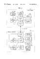
- FIG. 1 is a block diagram showing a configuration of a first embodiment.
- FIG. 2 is a flowchart for explaining the first embodiment.
- FIG. 3 is a flowchart for explaining a second embodiment.
- FIG. 4 is a block diagram showing a configuration of the second embodiment.
- FIG. 5 shows a screen display in the second embodiment.
- FIG. 6 is a block diagram showing a configuration of a third embodiment.
- FIG. 7 is a diagram showing one example of a network system constructed by using 1394 serial buses (in conformity with IEEE 1394).
- FIG. 8 is a diagram showing components of the 1394 serial bus (in conformity with IEEE 1394).
- FIG. 9 is a diagram showing an address space in the 1394 serial bus (in conformity with IEEE 1394).
- FIG. 10 is a sectional view of a 1394 serial bus cable.
- FIG. 11 is a chart for explaining a DS-Link coding method for a data transfer format (in conformity with IEEE 1394).
- FIG. 12 is a diagram showing one example of an actual network (in conformity with IEEE 1394).
- FIGS. 13A and 13B are diagrams for explaining processes of requesting the use of the bus and permitting the use of the bus.
- FIG. 14 is a chart showing state transition over time during asynchronous transfer (in conformity with IEEE 1394).
- FIG. 15 shows an example of a packet format for use in the asynchronous transfer mode(in conformity with IEEE 1394).
- FIG. 16 is a chart showing state transition over time during isochronous transfer (in conformity with IEEE 1394).
- FIG. 17 shows an example of a packet format for use in the isochronous transfer mode (in conformity with IEEE 1394).
- FIG. 18 is a chart showing transfer state transition on the bus over time when an isochronous transfer and an asynchronous transfer are executed in mixed fashion (in conformity with IEEE 1394).
- FIG. 19 is a flowchart showing a general sequence 1 from a bus reset to a decision of node IDs (in conformity with IEEE 1394).
- FIG. 20 is a flowchart showing a general sequence 2 from a bus reset to a decision of node IDs (in conformity with IEEE 1394).
- FIG. 21 is a flowchart showing a general sequence from a bus reset to a decision of node IDs (in conformity with IEEE 1394).
- FIG. 22 is a flowchart showing a sequence of an arbitration process(in conformity with IEEE 1394).
- FIG. 23 shows address locations in a configuration ROM.
- FIG. 24 shows screen display 1 in the related art.
- FIG. 25 shows a PC and a video camera connected to each other in the related art.
- FIG. 26 shows screen display 2 in the related art.
- FIG. 27 shows screen display 3 in the related art.
- FIG. 28 is a table showing examples of camera setting commands.
- FIG. 29 is a flowchart showing the third embodiment.
- FIG. 1 is a block diagram showing a configuration of a first embodiment.
- a video camera 1 A and a personal computer (PC) 1 B are connected to each other by a 1394 serial bus cable 108 .
- PC personal computer
- numeral 101 denotes a lens
- 102 denotes a signal processing unit which includes an image pickup device for converting light inputted through the lens 101 into an image signal, and which converts the image signal outputted from the image pickup device into a digital image signal.
- Numeral 103 denotes a control unit for controlling the entirety of the video camera
- 104 denotes one or more camera control parameters read by the control unit 103 for controlling the lens 101 and the signal processing unit 102 to produce the digital image signal.
- Numeral 105 denotes a digital interface for receiving and outputting the digital image signal, various control information, etc.
- 106 denotes a volatile memory from and into which data is read and written by the control unit 103 , the volatile memory temporarily storing camera setting values, etc. which are inputted from the digital interface 105 .
- Numeral 107 denotes a non-volatile memory from and into which data is read and written by the control unit 103 , the non-volatile memory finally storing the camera setting values, etc. which are inputted from the digital interface 105 .
- Numeral 109 denotes a digital interface for receiving the digital image from the video camera 1 A via the 1394 serial bus 108 and outputting various command data, etc. from a control unit 112 to the 1394 serial bus 108
- 110 denotes a connection detector for detecting whether the video camera is connected to the 1394 serial bus 108
- Numeral 111 denotes a user operating panel, such as a keyboard or a pointing device, through which the user operates the PC
- 112 denotes a control unit for controlling the entirety of the PC.
- Numeral 113 denotes one or more camera setting parameters read, written and changed by the control unit 112 in accordance with an input from the user operating panel 111
- 114 denotes a hard disk for storing the camera setting parameters 113 in the form of a file
- Numeral 115 denotes an image processing unit which includes an image memory for storing the digital image information inputted from the video camera 1 A via the digital interface 109 , and which can apply a digital effect to the image in the memory upon receiving a command from the control unit 112 .
- Numeral 116 denotes an image display unit for producing a window display image based on the digital image information outputted from the image processing unit 115 and the camera setting parameters, and outputting the produced image to a monitor 117 .
- the video camera 1 A receives the camera setting parameters and a command, such as “Set” or “Write”, from the digital interface 105 , and carries out an internal operation corresponding to the command. Specifically, when the camera setting parameters and the command “Set” are inputted, the control unit 103 sets the inputted parameters in the volatile memory 106 , and controls the lens 101 and the signal processing unit 102 by using those parameters temporarily. Also, when the camera setting parameters and the command “Write” are inputted, the control unit 103 writes the inputted parameters in both the volatile memory 106 and the non-volatile memory 107 , and controls the lens 101 and the signal processing unit 102 by using those parameters after that.
- the inputted camera setting parameters mean setting values of parameters capable of controlling the lens and the signal processing system to change the output image, such as tint, color gain, f-stop number and shutter speed, as described above in connection with the related art.
- the operation of a camera setting application on the PC side in the first embodiment will be described below in more detail with reference to a flowchart of FIG. 2 .
- the camera setting application presents the same screen display as shown in FIG. 24 .
- a simulation mode in this embodiment means a mode in which the user can change the camera setting parameters in the PC even with the PC not connected to the video camera, and can confirm an image resulted from the parameter change on the monitor screen.
- a camera mode in this embodiment means a mode in which the user can actually change the camera setting parameters in the video camera with the video camera connected to the PC, while confirming an image transmitted from the video camera, thereby optimizing the image.
- a program is first started in the simulation mode in step S 1201 .
- step S 1202 it is checked in step S 1202 whether the mode is switched over to the camera mode. If not switched over, the control unit enters a simulation mode process in step S 1207 . In the simulation mode process, the control unit executes such operations as receiving an input from the user operating panel 111 , outputting a command to the image processing unit 115 corresponding to a changed one of the camera setting parameters 113 , controlling the image display unit 116 to switch over the monitor screen, and storing the camera setting parameters 113 in the hard disk 114 in the form of a file.
- step S 1208 it is checked again in step S 1208 whether the mode is switched over to the camera mode. If not switched over, the simulation mode process is resumed in step S 1207 .
- step S 1203 If switched over, it is checked in step S 1203 whether the video camera is connected, by referring to the connection detector 110 . If not connected, the control unit returns to step S 1202 again to repeat a loop process while it is on standby for the next operation.
- step S 1204 If connected, one or more of the camera setting parameters 113 (which have been changed by simulation) are outputted in step S 1204 from the digital interface 109 , thereby changing the corresponding camera setting parameters in the video camera connected to the PC.
- a data match is established between the PC and the video camera connected to the PC at the time when the video camera is initially connected.
- a step S 1205 a camera adjustment process is executed with the matched state being as an initial state.
- the control unit executes such operations as receiving an input from the user operating panel 111 , outputting a parameter and a command from the digital interface 109 corresponding to changed one of the camera setting parameters 113 , displaying a screen of the image data transmitted from the video camera, and storing the camera setting parameters 113 in the hard disk 114 in the form of a file.
- step S 1206 it is checked again in step S 1206 whether the mode is switched over to the simulation mode. If not switched over, the control unit returns to step S 1205 again to resume the camera adjustment process, and if switched over, it goes to step S 1207 for shift to the simulation process.
- FIG. 3 is a flowchart of a camera setting application for explaining the second embodiment of the present invention.
- the control shown in FIG. 3 is executed with a configuration shown in a block diagram of FIG. 4 .
- the second embodiment will be described below with reference to FIGS. 3 and 4.
- a program is first started in the simulation mode in step S 1301 .
- step S 1302 it is checked in step S 1302 whether the mode is switched over to the camera mode. If not switched over, the control unit enters a simulation mode process in step S 1309 . In the simulation mode process, the control unit executes such operations as receiving an input from the user operating panel 111 , outputting a command to the image processing unit 115 corresponding to a changed one of the camera setting parameters 113 , controlling the image display unit 116 to switch over the monitor screen, and storing the camera setting parameters 113 in the hard disk 114 in the form of a file.
- step S 1310 it is checked again in step S 1310 whether the mode is switched over to the camera mode. If not switched over, the simulation mode process is resumed in step S 1309 .
- step S 1303 If switched over, it is checked in step S 1303 whether the video camera is connected, by referring to the connection detector 110 . If not connected, the control unit returns to step S 1302 again to repeat a loop process while it is on standby for the next operation.
- the processing so far described is exactly the same as in the first embodiment.
- the control unit 112 issues a command to read the camera setting parameters, such as tint, color gain, f-stop number and shutter speed, to the video camera via the digital interface 109 .
- the control unit 103 in the video camera read requests one or more of the camera setting parameters from the volatile memory 106 or the non-volatile memory 107 , and transmits the read data to the PC via the digital interface 105 .
- the control unit 112 on the PC side reads the above parameters in the video camera connected to the PC, and then stores them as camera-side read parameters 118 on the PC side.
- step S 1305 the control unit 112 compares the camera-side read parameters 118 and the camera setting parameters 113 currently existing in the PC. Depending on a compared result, in step S 1306 , the control unit 112 displays the camera setting parameters on a screen image of the camera setting application. Specifically, if the compared result shows a discrepancy in data values between the video camera and the PC, the control unit 112 issues an alarm.
- FIG. 5 shows a screen image of the camera setting application which includes an alarm display produced through the above-described procedures.
- the screen image of FIG. 5 illustrates an example in which the shutter speed value differs between the video camera and the PC.
- the shutter speed display is highlighted as indicated by 501 .
- a subwindow 502 for prompting the user to select a subsequent process is additionally displayed.
- the control unit 112 enters a camera adjustment process in a step S 1307 . If the alarm display described above is produced, the control unit 112 receives an input from the user. In other words, the user selects one of two buttons on the subwindow 502 by using the user operating panel 111 in the form of, e.g., a pointing device, thereby deciding with which data two different data should be matched.
- the control unit 112 rewrites a corresponding one of the camera setting parameters 113 to the value of the corresponding camera-side read parameter 118 . Conversely, if the button indicating “SET TO PC SIDE SPEED” is selected, the control unit 112 rewrites a corresponding one of the camera-side read parameters 118 to the value of the corresponding camera setting parameter 113 , and also outputs that camera setting parameter 113 through the digital interface 109 for changing the corresponding camera-side read parameter in the video camera connected to the PC. As a result, a data match is established between the PC and the video camera connected to the PC at the time when the video camera is initially connected.
- This third embodiment intends to achieve the above-described data match when a plurality of devices are connected to a network according to one feature of the 1394 serial bus connection. This point will be described below.
- FIG. 6 is a block diagram showing a configuration of the third embodiment.
- Numerals 601 to 603 denote video cameras connected by the 1394 serial buses, and 608 denotes a PC for setting parameters of the video cameras.
- the video cameras 601 to 603 are internally given WWUID( 1 ) to WWUID(N) as IDs which are used in the 1394 serial bus network and specific to the respective cameras.
- the PC 608 can read the WWUIDs via the 1394 serial buses, and conversely can perform such operations as receiving image information from only one of the video cameras having the particular WWUID, and producing a camera parameter setting command to the video cameras having the particular WWUID.
- a camera setting application in this embodiment can hold camera setting parameters for a plurality of video cameras, and also can select a particular one of the plurality of video cameras connected to the network by utilizing the specific WWUID so that camera parameters of the selected one video camera may be set separately.
- Numeral 609 denotes a 1394 digital interface
- 610 denotes a connection detector receiving a particular WWUID from the control unit 612 and detecting whether the video camera having particular WWUID is connected to the network.
- Numeral 611 denotes a user operating panel for operating the camera setting application, such as selecting the video camera and changing the camera setting parameters.
- Numeral 612 denotes a control unit for controlling the entirety of the application system, and denotes a selected VIDEO No. memory for storing the video camera number selected from the user operating panel 611 .
- Numeral 614 denotes a camera setting parameter table for holding WWUIDs corresponding to the VIDEO Nos. and camera setting parameter groups for the corresponding video cameras.
- Numeral 615 denotes an image processing unit which includes an image memory for storing digital image information inputted from the video camera corresponding to the selected VIDEO No. via the digital interface 109 , and which can apply a digital effect to the image in the memory upon receiving a command from the control unit 612 .
- Numeral 616 denotes an image display unit for producing a window display image based on the digital image information outputted from the image processing unit 615 and the camera setting parameters, and outputting the produced image to a monitor 617 .
- Numeral 617 denotes a hard disk for storing the camera setting parameters in the form of a file along with the WWUID of the selected video camera.
- step S 2901 the camera setting application starts a program in the camera mode.
- step S 2902 the control unit 612 reads a camera setting parameter file stored beforehand, and develops read data in the camera setting parameter table 614 .
- step S 2903 the control unit 612 waits for a camera selection input from the user.
- step S 2904 If the camera selection input is applied, processing goes to step S 2904 to store the VIDEO No. of the selected video camera in the selected VIDEO No. memory 613 .
- control unit 612 can select a particular one of the video cameras externally connected by the 1394 serial buses by referring to the WWUID corresponding to the decided VIDEO No. in the camera setting parameter table 614 .
- control unit 612 transmits the WWUID selected in step S 2905 to the connection detector 610 to detect whether the video camera having the selected WWUID is connected to the 1394 serial bus network.
- control unit 612 repeats a loop process while it is on standby for the next operation. If connected, the control unit 612 outputs in step S 2906 the camera setting parameters, which are stored in the camera setting parameter table 614 and correspond to the selected VIDEO No., to the video camera having the selected WWUID from the digital interface 609 . After that, the control unit 612 enters step S 2907 for a camera adjustment process, described above in connection with the related art, with a resultant state being as an initial state.
- values of the camera setting parameters in the selected video camera may be read and the read data may be used as first display data in the camera setting application as with the second embodiment.
- the object of the present invention can also be achieved by supplying, to a system or apparatus, a storage medium which stores program codes of software for realizing the functions of any of the above-described embodiments, and causing a computer (or CPU and/or MPU) in the system or apparatus to read and execute the program codes stored in the storage medium.
- the program codes read out of the storage medium serve in themselves to realize the functions of any of the above-described embodiments, and hence the storage medium storing the program codes comprises the present invention.
- Storage mediums for use in supplying the program codes may be, e.g., floppy disks, hard disks, optical disks, magneto-optic disks, CD-ROMs, CD-Rs, magnetic tapes, nonvolatile memory cards, and ROMS.
- the present invention involves such a case where the program codes read out of the storage medium are written into a memory provided in a function add-on board mounted in the computer or a function add-on unit connected to the computer, and a CPU or the like incorporated in the function add-on board or unit executes part or whole of the actual process in accordance with instructions from the program codes, thereby realizing the function of any of the above-described embodiments.
- the present invention is not limited to the embodiments, but also applicable to other types of imaging devices such as a digital camera, a silver salt camera, and a scanner.
- data is transmitted from the control device side to the imaging device side in the above-described embodiments, data may be transmitted from the imaging device side to the control device side in a reverse direction.
- a mismatch between setting values on the PC side and camera setting values in the video camera which occurred immediately after the connection therebetween can be automatically avoided immediately after the PC and the video camera are connected again.
- a mismatch between setting values on the PC side, which have been changed upon execution of a simulation, and unchanged setting values in the video camera can be automatically avoided immediately after the PC and the video camera are connected again.
- a mismatch between setting values on the PC side, which correspond to a particular one of the video cameras, and camera setting values in the particular video camera immediately after the connection therebetween can be avoided.
- a mismatch between setting values on the PC side, which have been changed upon execution of the simulation, and unchanged setting values in a particular one of the video cameras can be automatically avoided immediately after the PC and the particular video camera are connected again.
- a particular one of the video cameras can be surely selected by utilizing IDs specific to the video cameras, and a mismatch between setting values on the PC side, which have been changed and correspond to the selected video camera, and camera setting values in the selected video camera can be automatically avoided.
- a mismatch between a display of setting values on the PC side, which correspond to a particular one of the video cameras, and camera setting values in the particular video camera immediately after the connection therebetween can be avoided.
- a particular one of the video cameras can be surely selected by utilizing IDs specific to the video cameras, and a mismatch between a display of setting values on the PC side, which correspond to the particular video camera, and camera setting values in the selected video camera immediately after the connection therebetween can be avoided.
Landscapes
- Engineering & Computer Science (AREA)
- Signal Processing (AREA)
- Multimedia (AREA)
- Computer Networks & Wireless Communication (AREA)
- Human Computer Interaction (AREA)
- Studio Devices (AREA)
- Closed-Circuit Television Systems (AREA)
- Information Transfer Systems (AREA)
Priority Applications (1)
| Application Number | Priority Date | Filing Date | Title |
|---|---|---|---|
| US10/234,205 US7050042B2 (en) | 1998-07-30 | 2002-09-05 | Control system for controlling an imaging device and a personal computer wherein imaging device control conditions may be freely set between the imaging device and the personal computer |
Applications Claiming Priority (3)
| Application Number | Priority Date | Filing Date | Title |
|---|---|---|---|
| JP10-216129 | 1998-07-30 | ||
| JP21612998A JP3423620B2 (ja) | 1998-07-30 | 1998-07-30 | 撮像装置及び制御装置及び撮像装置制御システム及びその制御方法及び記憶媒体 |
| JP216129/1998 | 1998-07-30 |
Related Child Applications (1)
| Application Number | Title | Priority Date | Filing Date |
|---|---|---|---|
| US10/234,205 Continuation US7050042B2 (en) | 1998-07-30 | 2002-09-05 | Control system for controlling an imaging device and a personal computer wherein imaging device control conditions may be freely set between the imaging device and the personal computer |
Publications (2)
| Publication Number | Publication Date |
|---|---|
| US20020101514A1 US20020101514A1 (en) | 2002-08-01 |
| US6498598B2 true US6498598B2 (en) | 2002-12-24 |
Family
ID=16683724
Family Applications (2)
| Application Number | Title | Priority Date | Filing Date |
|---|---|---|---|
| US09/356,460 Expired - Lifetime US6498598B2 (en) | 1998-07-30 | 1999-07-19 | Imaging device system, control method for the system, imaging device, control device, control method for the imaging device, control method for the control device, and storage medium |
| US10/234,205 Expired - Lifetime US7050042B2 (en) | 1998-07-30 | 2002-09-05 | Control system for controlling an imaging device and a personal computer wherein imaging device control conditions may be freely set between the imaging device and the personal computer |
Family Applications After (1)
| Application Number | Title | Priority Date | Filing Date |
|---|---|---|---|
| US10/234,205 Expired - Lifetime US7050042B2 (en) | 1998-07-30 | 2002-09-05 | Control system for controlling an imaging device and a personal computer wherein imaging device control conditions may be freely set between the imaging device and the personal computer |
Country Status (4)
| Country | Link |
|---|---|
| US (2) | US6498598B2 (ja) |
| EP (1) | EP0977431B1 (ja) |
| JP (1) | JP3423620B2 (ja) |
| DE (1) | DE69930694T2 (ja) |
Cited By (15)
| Publication number | Priority date | Publication date | Assignee | Title |
|---|---|---|---|---|
| US20020051216A1 (en) * | 2000-03-10 | 2002-05-02 | Meta Controls, Inc. | Smart camera |
| US6578095B1 (en) * | 1998-10-27 | 2003-06-10 | Seiko Epson Corporation | Data transfer control device for transferring data among a plurality of nodes and electronic equipment |
| US20030202015A1 (en) * | 2002-04-30 | 2003-10-30 | Battles Amy E. | Imaging device user interface method and apparatus |
| US20030226099A1 (en) * | 2002-05-28 | 2003-12-04 | Tony Tsai | Method for communicating data between digital camera and portable electronic communication device |
| US20040257333A1 (en) * | 2003-06-18 | 2004-12-23 | Axisoft Technologies Inc. | Control system for image input device |
| US20050007479A1 (en) * | 2003-05-02 | 2005-01-13 | Yavuz Ahiska | Multiple object processing in wide-angle video camera |
| US20050090907A1 (en) * | 2000-03-10 | 2005-04-28 | Adept Technology, Inc | Smart camera |
| US7142244B1 (en) * | 2002-08-29 | 2006-11-28 | Sprint Spectrum L.P. | Digital camera with integrated cable storage |
| US7161619B1 (en) * | 1998-07-28 | 2007-01-09 | Canon Kabushiki Kaisha | Data communication system, data communication control method and electronic apparatus |
| US20080025597A1 (en) * | 2006-07-21 | 2008-01-31 | Hitachi, Ltd. | Image Processing Device |
| US7555409B1 (en) * | 2004-10-18 | 2009-06-30 | Kla-Tencor Corporation | Daisy chained topology |
| US20090231293A1 (en) * | 2008-03-12 | 2009-09-17 | Alpine Electronics, Inc. | Touch panel input device and processing execution method |
| US20100002071A1 (en) * | 2004-04-30 | 2010-01-07 | Grandeye Ltd. | Multiple View and Multiple Object Processing in Wide-Angle Video Camera |
| US9602700B2 (en) | 2003-05-02 | 2017-03-21 | Grandeye Ltd. | Method and system of simultaneously displaying multiple views for video surveillance |
| US20180015811A1 (en) * | 2016-07-12 | 2018-01-18 | Myongji University Industry And Academia Cooperation Foundation | Apparatus for controlling tint of display panel provided on vehicle window to adjust light transmittance |
Families Citing this family (31)
| Publication number | Priority date | Publication date | Assignee | Title |
|---|---|---|---|---|
| JP4487330B2 (ja) * | 1999-04-16 | 2010-06-23 | フジノン株式会社 | レンズ制御装置 |
| JP2001309247A (ja) * | 2000-04-19 | 2001-11-02 | Matsushita Electric Ind Co Ltd | 高周波信号受信装置 |
| JP2002041871A (ja) * | 2000-07-24 | 2002-02-08 | Tsubasa System Co Ltd | 車両の修理費の見積システム |
| JP2002073542A (ja) * | 2000-08-31 | 2002-03-12 | Sony Corp | サーバの使用予約方法、予約管理装置およびプログラム格納媒体 |
| US6980234B2 (en) * | 2000-10-19 | 2005-12-27 | Canon Kabushiki Kaisha | System for changing setup of first device that executes predetermined function by second device and these devices |
| JP2002185938A (ja) * | 2000-12-15 | 2002-06-28 | Olympus Optical Co Ltd | 電子カメラシステム、電子カメラ、サーバコンピュータおよび携帯情報端末 |
| JP4551571B2 (ja) * | 2001-01-26 | 2010-09-29 | キヤノン株式会社 | 放射線撮像装置 |
| KR100398878B1 (ko) | 2001-02-05 | 2003-09-19 | 삼성전자주식회사 | 컴퓨터를 이용한 디지털 비디오 캠코더의 환경설정방법 |
| KR100395567B1 (ko) * | 2001-05-10 | 2003-08-21 | 삼성전자주식회사 | 설정치를 공유하는 콤비네이션 시스템 및 콤비네이션시스템의 환경 설정방법 |
| US7136094B2 (en) * | 2002-02-22 | 2006-11-14 | Hewlett-Packard Development Company, L.P. | Share link between image capturing devices |
| US7170557B2 (en) * | 2002-03-26 | 2007-01-30 | Eastman Kodak Company | Modular digital imaging system |
| US20030236800A1 (en) * | 2002-06-19 | 2003-12-25 | Goeltzenleuchter Courtney D. | Dynamic recovery system and method |
| US20040017490A1 (en) * | 2002-07-25 | 2004-01-29 | Chih-Chung Lin | Image-capturing device controlled through internet and method for operating the same |
| JP4084263B2 (ja) * | 2002-08-13 | 2008-04-30 | 株式会社日立国際電気 | パラメータ設定方法 |
| CN100393122C (zh) | 2002-08-13 | 2008-06-04 | 株式会社日立国际电气 | 可改变物体检测条件的物体检测方法和物体检测装置 |
| US7318137B2 (en) * | 2003-01-29 | 2008-01-08 | Steven Bress | Write protection for computer long-term memory devices with multi-port selective blocking |
| US8045009B2 (en) * | 2004-05-10 | 2011-10-25 | Hewlett-Packard Development Company, L.P. | Image-exposure systems and methods using detecting motion of a camera to terminate exposure |
| US20060044394A1 (en) * | 2004-08-24 | 2006-03-02 | Sony Corporation | Method and apparatus for a computer controlled digital camera |
| US7738011B2 (en) * | 2004-09-21 | 2010-06-15 | Hitachi Kokusai Electric Inc. | Camera control system |
| JP2006287911A (ja) * | 2005-03-07 | 2006-10-19 | Fuji Photo Film Co Ltd | 画像出力システム、撮像装置、出力装置、画像出力方法、撮像方法、出力方法、及びプログラム |
| JP2007074504A (ja) * | 2005-09-08 | 2007-03-22 | Konica Minolta Opto Inc | 撮像装置 |
| JP2007129323A (ja) * | 2005-11-01 | 2007-05-24 | Toshiba Corp | 通信装置、通信システム |
| JP4735255B2 (ja) * | 2005-12-29 | 2011-07-27 | オムロン株式会社 | 画像処理装置および画像処理装置の動作条件設定方法 |
| JP5173475B2 (ja) * | 2008-02-19 | 2013-04-03 | キヤノン株式会社 | リモートコントローラ装置、その制御方法及びプログラム |
| DE202008009834U1 (de) | 2008-07-22 | 2009-12-10 | Liebherr-Elektronik Gmbh | Kamera zum Einsatz in einem digitalen Netzwerk |
| JP5730634B2 (ja) * | 2011-03-24 | 2015-06-10 | オリンパス株式会社 | 画像処理装置 |
| JP5888873B2 (ja) * | 2011-05-12 | 2016-03-22 | オリンパス株式会社 | 画像送信装置及び撮像表示システム |
| US9137428B2 (en) * | 2012-06-01 | 2015-09-15 | Microsoft Technology Licensing, Llc | Storyboards for capturing images |
| EP3169069A1 (en) * | 2015-11-10 | 2017-05-17 | FEI Company | Systems and methods for imaging device interfaces |
| EP3343286B1 (en) | 2016-12-27 | 2021-08-18 | Canon Kabushiki Kaisha | Display control apparatus and control method therefor |
| GB2586653B (en) * | 2019-09-02 | 2023-04-12 | Milestone Systems As | Method and system for improving settings of a camera images of which are used to perform a particular task |
Citations (21)
| Publication number | Priority date | Publication date | Assignee | Title |
|---|---|---|---|---|
| US4858012A (en) * | 1987-03-19 | 1989-08-15 | Hiromasa Hino | Camera having automatically controllable shooting features |
| US5039847A (en) | 1989-03-24 | 1991-08-13 | Omron Corporation | Image processing apparatus having an image scanner |
| US5068735A (en) * | 1989-08-22 | 1991-11-26 | Fuji Photo Optical Co., Ltd. | System for controlling the aiming direction, focus, zooming, and/or position of a television camera |
| JPH05276516A (ja) | 1992-03-27 | 1993-10-22 | Omron Corp | 入力インターフェイス装置 |
| JPH06153204A (ja) | 1992-11-10 | 1994-05-31 | Eastman Kodak Japan Kk | 電子カメラ及び電子カメラを使用した撮影装置 |
| WO1994024813A1 (en) | 1993-04-21 | 1994-10-27 | Kinya Washino | Multimedia video production system |
| JPH07193806A (ja) | 1992-02-12 | 1995-07-28 | Tokyo Kumahira:Kk | 監視カメラシステム |
| JPH07240871A (ja) | 1993-12-15 | 1995-09-12 | Eastman Kodak Co | コンピュータから設定される任意のパラメータを与える携帯型電子カメラ |
| EP0674435A1 (en) | 1994-02-28 | 1995-09-27 | Canon Kabushiki Kaisha | Image sensing apparatus |
| US5479206A (en) * | 1992-02-04 | 1995-12-26 | Fuji Photo Film Co., Ltd. | Imaging system, electronic camera, computer system for controlling said electronic camera, and methods of controlling same |
| JPH0824222A (ja) | 1994-07-18 | 1996-01-30 | Canon Inc | 眼科用記録システム制御装置 |
| EP0715453A2 (en) | 1994-11-28 | 1996-06-05 | Canon Kabushiki Kaisha | Camera controller |
| EP0734157A2 (en) | 1995-03-20 | 1996-09-25 | Canon Kabushiki Kaisha | Camera control system |
| JPH08265683A (ja) | 1995-03-24 | 1996-10-11 | Canon Inc | 撮像装置及びその外部制御装置 |
| EP0748132A2 (en) | 1995-06-08 | 1996-12-11 | Sony Corporation | Method of and apparatus for setting up a video device |
| EP0754994A2 (en) | 1995-07-21 | 1997-01-22 | Canon Kabushiki Kaisha | Control system and units removably attachable to the same |
| US5754227A (en) | 1994-09-28 | 1998-05-19 | Ricoh Company, Ltd. | Digital electronic camera having an external input/output interface through which the camera is monitored and controlled |
| US5942983A (en) * | 1995-12-07 | 1999-08-24 | Sony Corporation | Assuring data read/write operation in an electronic appliance |
| US6084631A (en) * | 1995-03-24 | 2000-07-04 | Ppt Vision, Inc. | High-speed digital video serial link |
| US6100812A (en) * | 1996-06-04 | 2000-08-08 | Sony Corporation | Communication control method, communication system and electronic equipment used for it |
| US6161933A (en) * | 1996-07-12 | 2000-12-19 | Arnold & Richter Cine Technik Gmbh & Co. Betriebs Kg | Device for controlling, regulating and monitoring a motion-picture camera |
Family Cites Families (3)
| Publication number | Priority date | Publication date | Assignee | Title |
|---|---|---|---|---|
| JPH0698225A (ja) | 1992-09-14 | 1994-04-08 | Sony Corp | ビデオカメラコントロールシステム |
| JPH1056586A (ja) * | 1996-08-13 | 1998-02-24 | Nikon Corp | 撮像装置 |
| JP3405092B2 (ja) * | 1996-09-30 | 2003-05-12 | ソニー株式会社 | カメラ制御装置、撮像システム及びその制御方法 |
-
1998
- 1998-07-30 JP JP21612998A patent/JP3423620B2/ja not_active Expired - Lifetime
-
1999
- 1999-07-19 US US09/356,460 patent/US6498598B2/en not_active Expired - Lifetime
- 1999-07-22 EP EP99305832A patent/EP0977431B1/en not_active Expired - Lifetime
- 1999-07-22 DE DE69930694T patent/DE69930694T2/de not_active Expired - Lifetime
-
2002
- 2002-09-05 US US10/234,205 patent/US7050042B2/en not_active Expired - Lifetime
Patent Citations (21)
| Publication number | Priority date | Publication date | Assignee | Title |
|---|---|---|---|---|
| US4858012A (en) * | 1987-03-19 | 1989-08-15 | Hiromasa Hino | Camera having automatically controllable shooting features |
| US5039847A (en) | 1989-03-24 | 1991-08-13 | Omron Corporation | Image processing apparatus having an image scanner |
| US5068735A (en) * | 1989-08-22 | 1991-11-26 | Fuji Photo Optical Co., Ltd. | System for controlling the aiming direction, focus, zooming, and/or position of a television camera |
| US5479206A (en) * | 1992-02-04 | 1995-12-26 | Fuji Photo Film Co., Ltd. | Imaging system, electronic camera, computer system for controlling said electronic camera, and methods of controlling same |
| JPH07193806A (ja) | 1992-02-12 | 1995-07-28 | Tokyo Kumahira:Kk | 監視カメラシステム |
| JPH05276516A (ja) | 1992-03-27 | 1993-10-22 | Omron Corp | 入力インターフェイス装置 |
| JPH06153204A (ja) | 1992-11-10 | 1994-05-31 | Eastman Kodak Japan Kk | 電子カメラ及び電子カメラを使用した撮影装置 |
| WO1994024813A1 (en) | 1993-04-21 | 1994-10-27 | Kinya Washino | Multimedia video production system |
| JPH07240871A (ja) | 1993-12-15 | 1995-09-12 | Eastman Kodak Co | コンピュータから設定される任意のパラメータを与える携帯型電子カメラ |
| EP0674435A1 (en) | 1994-02-28 | 1995-09-27 | Canon Kabushiki Kaisha | Image sensing apparatus |
| JPH0824222A (ja) | 1994-07-18 | 1996-01-30 | Canon Inc | 眼科用記録システム制御装置 |
| US5754227A (en) | 1994-09-28 | 1998-05-19 | Ricoh Company, Ltd. | Digital electronic camera having an external input/output interface through which the camera is monitored and controlled |
| EP0715453A2 (en) | 1994-11-28 | 1996-06-05 | Canon Kabushiki Kaisha | Camera controller |
| EP0734157A2 (en) | 1995-03-20 | 1996-09-25 | Canon Kabushiki Kaisha | Camera control system |
| JPH08265683A (ja) | 1995-03-24 | 1996-10-11 | Canon Inc | 撮像装置及びその外部制御装置 |
| US6084631A (en) * | 1995-03-24 | 2000-07-04 | Ppt Vision, Inc. | High-speed digital video serial link |
| EP0748132A2 (en) | 1995-06-08 | 1996-12-11 | Sony Corporation | Method of and apparatus for setting up a video device |
| EP0754994A2 (en) | 1995-07-21 | 1997-01-22 | Canon Kabushiki Kaisha | Control system and units removably attachable to the same |
| US5942983A (en) * | 1995-12-07 | 1999-08-24 | Sony Corporation | Assuring data read/write operation in an electronic appliance |
| US6100812A (en) * | 1996-06-04 | 2000-08-08 | Sony Corporation | Communication control method, communication system and electronic equipment used for it |
| US6161933A (en) * | 1996-07-12 | 2000-12-19 | Arnold & Richter Cine Technik Gmbh & Co. Betriebs Kg | Device for controlling, regulating and monitoring a motion-picture camera |
Cited By (23)
| Publication number | Priority date | Publication date | Assignee | Title |
|---|---|---|---|---|
| US7161619B1 (en) * | 1998-07-28 | 2007-01-09 | Canon Kabushiki Kaisha | Data communication system, data communication control method and electronic apparatus |
| US6578095B1 (en) * | 1998-10-27 | 2003-06-10 | Seiko Epson Corporation | Data transfer control device for transferring data among a plurality of nodes and electronic equipment |
| US20020051216A1 (en) * | 2000-03-10 | 2002-05-02 | Meta Controls, Inc. | Smart camera |
| US20050090907A1 (en) * | 2000-03-10 | 2005-04-28 | Adept Technology, Inc | Smart camera |
| US6985780B2 (en) * | 2000-03-10 | 2006-01-10 | Adept Technology, Inc. | Smart camera |
| US6988008B2 (en) * | 2000-03-10 | 2006-01-17 | Adept Technology, Inc. | Smart camera |
| US20030202015A1 (en) * | 2002-04-30 | 2003-10-30 | Battles Amy E. | Imaging device user interface method and apparatus |
| US20030226099A1 (en) * | 2002-05-28 | 2003-12-04 | Tony Tsai | Method for communicating data between digital camera and portable electronic communication device |
| US6910176B2 (en) * | 2002-05-28 | 2005-06-21 | Inventec Appliances Corp. | Method for communicating data between digital camera and portable electronic communication device |
| US7142244B1 (en) * | 2002-08-29 | 2006-11-28 | Sprint Spectrum L.P. | Digital camera with integrated cable storage |
| US20050007479A1 (en) * | 2003-05-02 | 2005-01-13 | Yavuz Ahiska | Multiple object processing in wide-angle video camera |
| US7528881B2 (en) * | 2003-05-02 | 2009-05-05 | Grandeye, Ltd. | Multiple object processing in wide-angle video camera |
| US9602700B2 (en) | 2003-05-02 | 2017-03-21 | Grandeye Ltd. | Method and system of simultaneously displaying multiple views for video surveillance |
| US20040257333A1 (en) * | 2003-06-18 | 2004-12-23 | Axisoft Technologies Inc. | Control system for image input device |
| US20100002071A1 (en) * | 2004-04-30 | 2010-01-07 | Grandeye Ltd. | Multiple View and Multiple Object Processing in Wide-Angle Video Camera |
| US8427538B2 (en) | 2004-04-30 | 2013-04-23 | Oncam Grandeye | Multiple view and multiple object processing in wide-angle video camera |
| US7555409B1 (en) * | 2004-10-18 | 2009-06-30 | Kla-Tencor Corporation | Daisy chained topology |
| US20080025597A1 (en) * | 2006-07-21 | 2008-01-31 | Hitachi, Ltd. | Image Processing Device |
| US8184860B2 (en) * | 2006-07-21 | 2012-05-22 | Hitachi, Ltd. | Image processing device for controlling a plurality of tasks |
| US20090231293A1 (en) * | 2008-03-12 | 2009-09-17 | Alpine Electronics, Inc. | Touch panel input device and processing execution method |
| US8134538B2 (en) * | 2008-03-12 | 2012-03-13 | Alpine Electronics, Inc. | Touch panel input device and processing execution method |
| US20180015811A1 (en) * | 2016-07-12 | 2018-01-18 | Myongji University Industry And Academia Cooperation Foundation | Apparatus for controlling tint of display panel provided on vehicle window to adjust light transmittance |
| US10040338B2 (en) * | 2016-07-12 | 2018-08-07 | Myongji University Industry And Academia Cooperation Foundation | Apparatus for controlling tint of display panel provided on vehicle window to adjust light transmittance |
Also Published As
| Publication number | Publication date |
|---|---|
| US20020196197A1 (en) | 2002-12-26 |
| EP0977431A2 (en) | 2000-02-02 |
| US20020101514A1 (en) | 2002-08-01 |
| DE69930694D1 (de) | 2006-05-18 |
| US7050042B2 (en) | 2006-05-23 |
| EP0977431A3 (en) | 2002-09-04 |
| JP2000050241A (ja) | 2000-02-18 |
| DE69930694T2 (de) | 2006-09-14 |
| JP3423620B2 (ja) | 2003-07-07 |
| EP0977431B1 (en) | 2006-04-05 |
Similar Documents
| Publication | Publication Date | Title |
|---|---|---|
| US6498598B2 (en) | Imaging device system, control method for the system, imaging device, control device, control method for the imaging device, control method for the control device, and storage medium | |
| US7349011B2 (en) | Image pickup control apparatus, image pickup control method, image pickup control system, and storage medium | |
| US7936381B2 (en) | Management and setting of photographing condition of image sensing apparatus | |
| KR20010051014A (ko) | 데이터 전송 제어 장치 및 전자 기기 | |
| EP0959590B1 (en) | Data communication system operating at maximum data rate | |
| JP2000358033A (ja) | データ通信システム及びデータ通信方法 | |
| US6412076B1 (en) | Signal processing apparatus and image sensing apparatus | |
| JP3862371B2 (ja) | 電子機器及び制御方法 | |
| JP4006116B2 (ja) | 撮影条件管理装置、撮影条件管理方法、及び記憶媒体 | |
| US20060017811A1 (en) | Communication system, electronic apparatus, control apparatus, and computer-readable storage medium | |
| US6816993B1 (en) | Control method of electronic device controllable from external control apparatus by communication | |
| JP4217727B2 (ja) | ディジタル機器及びその制御方法 | |
| JP3814428B2 (ja) | 端末装置のカメラ制御方法 | |
| EP1521259A1 (en) | Information recording device and information recording method | |
| JP2001313875A (ja) | 映像モニタ装置及びその制御方法 | |
| JP2000138860A (ja) | 撮像装置、撮像装置の制御装置及びコンピュータ読み取り可能な記憶媒体 | |
| JP3890124B2 (ja) | データ通信システム、データ通信方法、データ通信ノードおよび記録媒体 | |
| JP2001309248A (ja) | 信号源選択装置及びtvモニタ装置 | |
| JP2001257685A (ja) | 情報信号処理装置及び情報信号処理方法並びに記憶媒体 | |
| JP2001309458A (ja) | 遠隔制御システム | |
| JP2004289857A (ja) | プリント方法、通信方法、プリント制御装置、及び通信制御装置 | |
| JP2003087883A (ja) | ネットワーク接続機器の制御システム | |
| JP2004260857A (ja) | 撮像制御装置、撮像制御方法、撮像制御システム、及び記憶媒体 | |
| JP2004001570A (ja) | 画像形成システム及び画像形成装置 | |
| KR20000025438A (ko) | 프로토콜 인터페이스 방법 |
Legal Events
| Date | Code | Title | Description |
|---|---|---|---|
| AS | Assignment |
Owner name: CANON KABUSHIKI KAISHA, JAPAN Free format text: ASSIGNMENT OF ASSIGNORS INTEREST;ASSIGNOR:WATANABE, YOSHIYUKI;REEL/FRAME:010116/0547 Effective date: 19990714 |
|
| STCF | Information on status: patent grant |
Free format text: PATENTED CASE |
|
| CC | Certificate of correction | ||
| FPAY | Fee payment |
Year of fee payment: 4 |
|
| FPAY | Fee payment |
Year of fee payment: 8 |
|
| FPAY | Fee payment |
Year of fee payment: 12 |