US6405776B1 - Hoop-casing device - Google Patents
Hoop-casing device Download PDFInfo
- Publication number
- US6405776B1 US6405776B1 US09/423,039 US42303999A US6405776B1 US 6405776 B1 US6405776 B1 US 6405776B1 US 42303999 A US42303999 A US 42303999A US 6405776 B1 US6405776 B1 US 6405776B1
- Authority
- US
- United States
- Prior art keywords
- counter
- tool
- bearing
- bearing part
- hoop
- Prior art date
- Legal status (The legal status is an assumption and is not a legal conclusion. Google has not performed a legal analysis and makes no representation as to the accuracy of the status listed.)
- Expired - Fee Related
Links
Images


Classifications
-
- B—PERFORMING OPERATIONS; TRANSPORTING
- B65—CONVEYING; PACKING; STORING; HANDLING THIN OR FILAMENTARY MATERIAL
- B65B—MACHINES, APPARATUS OR DEVICES FOR, OR METHODS OF, PACKAGING ARTICLES OR MATERIALS; UNPACKING
- B65B13/00—Bundling articles
- B65B13/18—Details of, or auxiliary devices used in, bundling machines or bundling tools
- B65B13/24—Securing ends of binding material
- B65B13/32—Securing ends of binding material by welding, soldering, or heat-sealing; by applying adhesive
- B65B13/327—Hand tools
Definitions
- the invention concerns a hoop-casing device for hooping an object with a heat-sealable plastic strip placed around it.
- Hoop-casing devices of the type mentioned above are multiply known, for instance from EP-0744342. They comprise a tool part and a counter-bearing part, the counter-bearing surfaces of which face each other and match each other and have a structure similar to a toothing to be able to grip the plastic strip as efficiently as possible during tensioning and friction-sealing.
- the object of the invention is to provide a hoop-casing device of the relevant generic type that does not have the above mentioned drawback.
- said object is attained in a hoop-casing device of the relevant generic type by providing a hoop-casing device for hooping an object with a heat-sealable plastic strip placed around the object;
- the hoop-casing device comprising a unit for tensioning the strip and for friction-sealing two overlapping strip parts of the tensioned strip;
- the unit comprising a tool part that can be rotatably driven about a rotation axis and having a generally cylindrical tool mantle surface, the unit further comprising a counter-bearing part having a counter-bearing surface facing the tool part and extending over a sector of the tool mantle surface and generally enclosing said sector; at least the counter-bearing surface of the counter-bearing part having a structure similar to toothing;
- the tool part and the counter-bearing part being mutually pivotable about a swivel axis that is parallel to the rotation axis to grip or release the overlapping strip parts
- the concave counter-bearing surface of the counter-bearing part is composed of several portions of parts that are arranged side by side, namely, composed of the plurality of outer faces of the holding blocks, which in contrast with the prior art allows rather small areas of the concave counter-bearing surface to be machined individually and the machining costs to be correspondingly reduced.
- Advantageous embodiments of the hoop-casing device according to the invention include making the outer faces of the holding blocks essentially planar and rectangular with edges parallel to the rotation axis and swivel axis.
- the holding blocks each are provided with an essentially planar and rectangular outer face, the edges of this outer face being parallel to the rotation axis and the swivel axis.
- Such holding blocks can then be machined economically and at the same time structured with an optimal toothing on one planar outer face.
- when being mounted they are adapted to be arranged side by side and fixed on the shoe in such a way that they end up all located on the mantle surface of a prism having edges essentially parallel to the rotation axis and the swivel axis.
- the holding blocks thus manufactured and mounted make up a counter-bearing surface of the counter-bearing part that approximately matches the generally cylindrical tool mantle surface of the tool part, which, in combination with the optimal toothing, allows the overlapping strip parts inserted therebetween to be well gripped and hold and to be applied high tensioning forces.
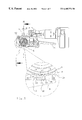
- FIG. 1 shows a side view of a hoop-casing device according to the invention together with a view of a partial domain of the hoop-casing device magnified by a factor of about six (magnifying glass view);
- FIG. 2 shows a sectional view of the hoop-casing device cut along line A—A of FIG. 1 together with a view of a partial domain of the hoop-casing device magnified by a factor of about one and a half (magnifying glass view);
- FIG. 3 shows a perspective explosion view of parts of the hoop-casing device in order to illustrate the fixation and arrangement of holding blocks at the hoop-casing device;
- FIG. 4 shows a perspective explosion view of the holding blocks of FIG. 3 magnified by a factor of about two in comparison with FIG. 3;
- FIG. 5 shows a top view of a part of the hoop-casing device shown in the magnifying glass view of FIG. 1, broken-off and magnified by a factor of about one and a half in comparison with said magnifying glass view, in order to illustrate the structural features and mutual arrangement of the holding blocks;
- FIG. 6 shows the hoop-casing device in a view that is the same as in FIG. 1 but for the plastic strip being inserted;
- FIG. 7 shows the hoop-casing device in a view that is the same as in FIG. 2 but for the plastic strip being inserted.
- the hoop-casing device according to the invention serves to hoop-case an object with a plastic strip placed around it and will be described with reference to an exemplary embodiment, it being understood that the invention must not be limited to this exemplary embodiment.
- the illustrated hoop-casing device comprises, at a housing 1 , a unit 2 for tensioning a heat-sealable plastic strip 3 and for friction-sealing two strip parts 4 and 5 of this plastic strip 3 that overlap each other.
- the unit 2 comprises a tool part 7 that has a generally cylindrical tool mantle surface 8 and that can be rotated about a rotation axis 6 and driven. Additionally, the unit 2 comprises a counter-bearing part 9 that in turn is provided with a counter-bearing surface 10 facing the tool part 7 and extending over a sector of the tool mantle surface and generally enclosing the latter.
- the counter-bearing surface 10 and, advantageously, the tool mantle surface 8 as well, are provided with structural features to allow to grip the plastic strip 3 as efficiently as possible.
- the counter-bearing surface 10 is provided with a special toothing that will be described more in detail below and may best be perceived in FIGS. 3, 4 and 5 .
- the tool part 7 and the counter-bearing part 9 can be swivelled relative to each other about a swivel axis 12 by means of a lever 11 , this swivel axis 12 being parallel to the rotation axis 6 .
- the counter-bearing part 9 comprises a separate shoe 13 that is made up of several parts.
- the shoe 13 is composed of three holding blocks 14 , 16 and 18 that are arranged side by side in angular sequence about the rotation axis 6 .
- These holding blocks 14 , 16 and 18 are provided with respective outer faces 15 , 17 and 19 adjacent to each other at edges 20 , 21 , 22 , 23 and that, taken together, form an outer face 24 of the shoe 13 and hence, the counter-bearing surface 10 of the counter-bearing part 9 as well.
- the outer faces 15 , 17 and 19 of the holding blocks 14 , 16 and 18 are essentially planar and rectangular.
- the edges 20 , 21 , 22 , 23 are disposed parallel to the rotation axis 6 and swivel axis 12 , and the outer faces 15 , 17 and 19 are located on a prismatic mantle surface that encloses the tool mantle surface 8 .
- the thus formed counter-bearing surface 10 of the counter-bearing part 9 approximately matches the cylindrical tool mantle surface 8 of the tool part 7 and allows the overlapping strip parts 4 and 5 of the plastic strip 3 inserted therebetween to be sufficiently well gripped and hold.
- FIGS. 3 and 5 How the shoe 13 or the holding blocks 14 , 16 and 18 , respectively, are fixed on the counter-bearing part 9 may best be perceived in FIGS. 3 and 5.
- the holding blocks 14 , 16 and 18 are located next to each other and resting against each other in a recess 25 of the counter-bearing part 9 with those edges 20 , 21 , 22 , 23 that are parallel to the rotation axis 6 and the swivel axis 12 constituting respective longer edges of the outer faces 15 , 17 and 19 , which are formed rectangular.
- the holding blocks 14 , 16 and 18 terminate on each side thereof in projections 26 , each of which protrudes under one of two clamping blocks 27 and 28 .
- These clamping blocks 27 and 28 are fixed on the counter-bearing part 9 with the help of screws 29 , guide pins 30 and washers 31 and in turn hold the holding blocks 14 , 16 and 18 when the screws 29 are tightened at the counter-bearing part 9 .
- the machining of the outer faces 15 , 17 and 19 of the holding blocks 14 , 16 and 18 eventually produces an embodiment with structural features such as for instance that which may best be perceived in FIGS. 3, 4 and 5 .
- the planar outer faces 15 , 17 and 19 of the holding blocks 14 , 16 and 18 allow and facilitate the machining of the holding blocks by milling or grinding in various directions essentially parallel to the outer faces while oriented at any desired angle to the longer edges 20 , 21 , 22 , 23 .
- the outer faces 15 , 17 and 19 of the holding blocks 14 , 16 and 18 are provided with any desired rows and patterns of diamond points 32 that are adapted to be pressed into the strip portion that rests against the counter-bearing part 9 and to hold it well during a clamping of the overlapping strip parts 4 and 5 of the plastic strip 3 between the tool part 7 and the counter-bearing part 9 .
Landscapes
- Engineering & Computer Science (AREA)
- Mechanical Engineering (AREA)
- Basic Packing Technique (AREA)
- Lining Or Joining Of Plastics Or The Like (AREA)
- Package Frames And Binding Bands (AREA)
- Orthopedics, Nursing, And Contraception (AREA)
- Surgical Instruments (AREA)
Applications Claiming Priority (3)
| Application Number | Priority Date | Filing Date | Title |
|---|---|---|---|
| CH971119 | 1997-05-13 | ||
| CH111997 | 1997-05-13 | ||
| PCT/CH1998/000137 WO1998051569A1 (fr) | 1997-05-13 | 1998-04-09 | Enrubanneuse |
Publications (1)
| Publication Number | Publication Date |
|---|---|
| US6405776B1 true US6405776B1 (en) | 2002-06-18 |
Family
ID=4202943
Family Applications (1)
| Application Number | Title | Priority Date | Filing Date |
|---|---|---|---|
| US09/423,039 Expired - Fee Related US6405776B1 (en) | 1997-05-13 | 1999-04-09 | Hoop-casing device |
Country Status (8)
| Country | Link |
|---|---|
| US (1) | US6405776B1 (fr) |
| EP (1) | EP0981479B1 (fr) |
| JP (1) | JP3932387B2 (fr) |
| AT (1) | ATE221487T1 (fr) |
| CA (1) | CA2289030C (fr) |
| DE (1) | DE59805011D1 (fr) |
| ES (1) | ES2180152T3 (fr) |
| WO (1) | WO1998051569A1 (fr) |
Cited By (5)
| Publication number | Priority date | Publication date | Assignee | Title |
|---|---|---|---|---|
| US20090065624A1 (en) * | 2007-09-10 | 2009-03-12 | Hsiu-Man Yu Chen | Structure of strip winding machine |
| US20130019764A1 (en) * | 2011-07-20 | 2013-01-24 | Pantech International Inc. | Rocker assembly of a strapping machine |
| CN104890920A (zh) * | 2015-05-13 | 2015-09-09 | 孙健 | 一种应用于捆扎机的新式齿板结构 |
| CN104890915A (zh) * | 2015-05-13 | 2015-09-09 | 孙健 | 一种托板三边承压结构 |
| CN104890922A (zh) * | 2015-05-13 | 2015-09-09 | 孙健 | 一种应用于捆扎机的x型齿板 |
Families Citing this family (4)
| Publication number | Priority date | Publication date | Assignee | Title |
|---|---|---|---|---|
| US6345648B1 (en) * | 2000-10-16 | 2002-02-12 | Illinois Toole Works Inc. | Gripper plug for hand strapping tool |
| AT514803B1 (de) * | 2013-12-19 | 2015-04-15 | Teufelberger Gmbh | Mobile Umreifungsvorrichtung |
| DE202015009004U1 (de) | 2015-07-08 | 2016-06-10 | LINDER GmbH | Umreifungsvorrichtung zum Sichern eines Packguts |
| DE102015111051A1 (de) | 2015-07-08 | 2017-01-12 | LINDER GmbH | Umreifungsvorrichtung zum Sichern eines Packguts |
Citations (8)
| Publication number | Priority date | Publication date | Assignee | Title |
|---|---|---|---|---|
| US3360017A (en) * | 1965-07-16 | 1967-12-26 | Signode Corp | Combination strapping tool |
| US3442732A (en) * | 1965-08-13 | 1969-05-06 | Signode Corp | Friction-fusion strap sealing |
| US3586572A (en) * | 1969-02-20 | 1971-06-22 | Signode Corp | Electrically controlled handtool for friction-fusing nonmetallic strap |
| US4015643A (en) * | 1976-01-21 | 1977-04-05 | Signode Corporation | Tensioning tool with self-energizing gripper plug |
| US4313779A (en) * | 1979-07-30 | 1982-02-02 | Signode Corporation | All electric friction fusion strapping tool |
| US5133532A (en) * | 1990-10-11 | 1992-07-28 | Illinois Tool Works Inc. | Method and apparatus for controlling tension in a strap loop |
| US5542239A (en) * | 1992-04-03 | 1996-08-06 | Sekisui Jushi Kabushiki Kaisha | Method for welding a packing band of thermoplastic resin and a welded band resulting therefrom |
| US5632851A (en) * | 1995-04-05 | 1997-05-27 | Pantech International, Inc. | Portable article strapping apparatus |
-
1998
- 1998-04-09 JP JP54865098A patent/JP3932387B2/ja not_active Expired - Fee Related
- 1998-04-09 CA CA002289030A patent/CA2289030C/fr not_active Expired - Fee Related
- 1998-04-09 WO PCT/CH1998/000137 patent/WO1998051569A1/fr active IP Right Grant
- 1998-04-09 ES ES98912183T patent/ES2180152T3/es not_active Expired - Lifetime
- 1998-04-09 AT AT98912183T patent/ATE221487T1/de not_active IP Right Cessation
- 1998-04-09 EP EP98912183A patent/EP0981479B1/fr not_active Expired - Lifetime
- 1998-04-09 DE DE59805011T patent/DE59805011D1/de not_active Expired - Fee Related
-
1999
- 1999-04-09 US US09/423,039 patent/US6405776B1/en not_active Expired - Fee Related
Patent Citations (8)
| Publication number | Priority date | Publication date | Assignee | Title |
|---|---|---|---|---|
| US3360017A (en) * | 1965-07-16 | 1967-12-26 | Signode Corp | Combination strapping tool |
| US3442732A (en) * | 1965-08-13 | 1969-05-06 | Signode Corp | Friction-fusion strap sealing |
| US3586572A (en) * | 1969-02-20 | 1971-06-22 | Signode Corp | Electrically controlled handtool for friction-fusing nonmetallic strap |
| US4015643A (en) * | 1976-01-21 | 1977-04-05 | Signode Corporation | Tensioning tool with self-energizing gripper plug |
| US4313779A (en) * | 1979-07-30 | 1982-02-02 | Signode Corporation | All electric friction fusion strapping tool |
| US5133532A (en) * | 1990-10-11 | 1992-07-28 | Illinois Tool Works Inc. | Method and apparatus for controlling tension in a strap loop |
| US5542239A (en) * | 1992-04-03 | 1996-08-06 | Sekisui Jushi Kabushiki Kaisha | Method for welding a packing band of thermoplastic resin and a welded band resulting therefrom |
| US5632851A (en) * | 1995-04-05 | 1997-05-27 | Pantech International, Inc. | Portable article strapping apparatus |
Cited By (6)
| Publication number | Priority date | Publication date | Assignee | Title |
|---|---|---|---|---|
| US20090065624A1 (en) * | 2007-09-10 | 2009-03-12 | Hsiu-Man Yu Chen | Structure of strip winding machine |
| US20130019764A1 (en) * | 2011-07-20 | 2013-01-24 | Pantech International Inc. | Rocker assembly of a strapping machine |
| US8387523B2 (en) * | 2011-07-20 | 2013-03-05 | Pantech International Inc. | Rocker assembly of a strapping machine |
| CN104890920A (zh) * | 2015-05-13 | 2015-09-09 | 孙健 | 一种应用于捆扎机的新式齿板结构 |
| CN104890915A (zh) * | 2015-05-13 | 2015-09-09 | 孙健 | 一种托板三边承压结构 |
| CN104890922A (zh) * | 2015-05-13 | 2015-09-09 | 孙健 | 一种应用于捆扎机的x型齿板 |
Also Published As
| Publication number | Publication date |
|---|---|
| ES2180152T3 (es) | 2003-02-01 |
| EP0981479B1 (fr) | 2002-07-31 |
| EP0981479A1 (fr) | 2000-03-01 |
| WO1998051569A1 (fr) | 1998-11-19 |
| CA2289030A1 (fr) | 1998-11-19 |
| JP2001524911A (ja) | 2001-12-04 |
| JP3932387B2 (ja) | 2007-06-20 |
| CA2289030C (fr) | 2006-08-29 |
| DE59805011D1 (de) | 2002-09-05 |
| ATE221487T1 (de) | 2002-08-15 |
Similar Documents
| Publication | Publication Date | Title |
|---|---|---|
| US6405776B1 (en) | Hoop-casing device | |
| US5201146A (en) | Portable rotary tool | |
| NO974816L (no) | Roterende sponkutterhode | |
| US5549025A (en) | Cutting strip with a cutting edge made of highly wear-resistant material | |
| EP0666144A1 (fr) | Dispositif pour le serrage d'une pièce sur un support plan tel que la table d'une machine outil | |
| JPS6373532A (ja) | ボンデイング装置 | |
| EP0231397A1 (fr) | Meule de noyau de connecteur optique et procede de rectification de noyau | |
| JP2911415B2 (ja) | せん断破砕機 | |
| BR8906513A (pt) | Eixo composto,processo e ordenada para a fabricacao do mesmo | |
| JP3790311B2 (ja) | ベニヤ単板の脱水装置 | |
| US5715878A (en) | Jig for a molder-planar | |
| JPS645759A (en) | Chamfering method for glass disc | |
| GB2360723A (en) | Sanding machine clamp bar | |
| JPH01311582A (ja) | 蛍光灯ランプソケット | |
| SU679324A1 (ru) | Резцедержатель | |
| JPH09239450A (ja) | 山形鋼の曲げ加工法およびその曲げ加工に用いる治具 | |
| JPS607761B2 (ja) | 光ファイバの切断装置 | |
| JPS6339764A (ja) | ラツプ盤におけるキヤリアの構造 | |
| JP2972774B1 (ja) | ケーブルクランプ装置 | |
| KR0143621B1 (ko) | 샌드페이퍼 절단장치 | |
| KR200150267Y1 (ko) | 로봇 드라이버용 키 어댑터 | |
| JP2003019653A (ja) | ストリップ側端研磨ブラシロール | |
| JPH0899291A (ja) | 切断装置 | |
| JPH09158489A (ja) | 建築物の外装施工用のシート固定具 | |
| KR20000008977U (ko) | 코일밴드 컷팅용 척 레버의 밴드 탈락 방지장치 |
Legal Events
| Date | Code | Title | Description |
|---|---|---|---|
| FPAY | Fee payment |
Year of fee payment: 4 |
|
| FEPP | Fee payment procedure |
Free format text: PAYOR NUMBER ASSIGNED (ORIGINAL EVENT CODE: ASPN); ENTITY STATUS OF PATENT OWNER: LARGE ENTITY |
|
| FPAY | Fee payment |
Year of fee payment: 8 |
|
| REMI | Maintenance fee reminder mailed | ||
| LAPS | Lapse for failure to pay maintenance fees | ||
| STCH | Information on status: patent discontinuation |
Free format text: PATENT EXPIRED DUE TO NONPAYMENT OF MAINTENANCE FEES UNDER 37 CFR 1.362 |
|
| FP | Lapsed due to failure to pay maintenance fee |
Effective date: 20140618 |