US6042683A - Method and device for producing an aspiration surface on an object, and electrical component obtained thereby - Google Patents
Method and device for producing an aspiration surface on an object, and electrical component obtained thereby Download PDFInfo
- Publication number
- US6042683A US6042683A US08/948,423 US94842397A US6042683A US 6042683 A US6042683 A US 6042683A US 94842397 A US94842397 A US 94842397A US 6042683 A US6042683 A US 6042683A
- Authority
- US
- United States
- Prior art keywords
- adhesive mass
- cover band
- aspiration
- planar
- mass
- Prior art date
- Legal status (The legal status is an assumption and is not a legal conclusion. Google has not performed a legal analysis and makes no representation as to the accuracy of the status listed.)
- Expired - Fee Related
Links
- 238000000034 method Methods 0.000 title claims abstract description 25
- 239000000853 adhesive Substances 0.000 claims abstract description 44
- 230000001070 adhesive effect Effects 0.000 claims abstract description 44
- 239000000463 material Substances 0.000 claims abstract description 8
- RSWGJHLUYNHPMX-ONCXSQPRSA-N abietic acid Chemical compound C([C@@H]12)CC(C(C)C)=CC1=CC[C@@H]1[C@]2(C)CCC[C@@]1(C)C(O)=O RSWGJHLUYNHPMX-ONCXSQPRSA-N 0.000 claims abstract description 3
- 238000004519 manufacturing process Methods 0.000 claims description 8
- 230000005855 radiation Effects 0.000 claims description 6
- 230000005670 electromagnetic radiation Effects 0.000 claims description 2
- 230000001678 irradiating effect Effects 0.000 claims description 2
- 238000000465 moulding Methods 0.000 abstract description 2
- 238000012545 processing Methods 0.000 description 6
- 230000015572 biosynthetic process Effects 0.000 description 2
- 238000013461 design Methods 0.000 description 2
- 238000005516 engineering process Methods 0.000 description 2
- 238000010438 heat treatment Methods 0.000 description 2
- 238000003780 insertion Methods 0.000 description 2
- 230000037431 insertion Effects 0.000 description 2
- 238000000926 separation method Methods 0.000 description 2
- 238000007493 shaping process Methods 0.000 description 2
- 238000005476 soldering Methods 0.000 description 2
- 230000004913 activation Effects 0.000 description 1
- 239000000654 additive Substances 0.000 description 1
- 230000000996 additive effect Effects 0.000 description 1
- 238000010924 continuous production Methods 0.000 description 1
- 238000011982 device technology Methods 0.000 description 1
- 230000000694 effects Effects 0.000 description 1
- 238000001704 evaporation Methods 0.000 description 1
- 230000008020 evaporation Effects 0.000 description 1
- 238000012986 modification Methods 0.000 description 1
- 230000004048 modification Effects 0.000 description 1
- 238000009417 prefabrication Methods 0.000 description 1
- 229910000679 solder Inorganic materials 0.000 description 1
- 239000012780 transparent material Substances 0.000 description 1
Images


Classifications
-
- H—ELECTRICITY
- H01—ELECTRIC ELEMENTS
- H01G—CAPACITORS; CAPACITORS, RECTIFIERS, DETECTORS, SWITCHING DEVICES, LIGHT-SENSITIVE OR TEMPERATURE-SENSITIVE DEVICES OF THE ELECTROLYTIC TYPE
- H01G2/00—Details of capacitors not covered by a single one of groups H01G4/00-H01G11/00
- H01G2/02—Mountings
- H01G2/06—Mountings specially adapted for mounting on a printed-circuit support
- H01G2/065—Mountings specially adapted for mounting on a printed-circuit support for surface mounting, e.g. chip capacitors
-
- H—ELECTRICITY
- H05—ELECTRIC TECHNIQUES NOT OTHERWISE PROVIDED FOR
- H05K—PRINTED CIRCUITS; CASINGS OR CONSTRUCTIONAL DETAILS OF ELECTRIC APPARATUS; MANUFACTURE OF ASSEMBLAGES OF ELECTRICAL COMPONENTS
- H05K13/00—Apparatus or processes specially adapted for manufacturing or adjusting assemblages of electric components
- H05K13/02—Feeding of components
- H05K13/021—Loading or unloading of containers
-
- H—ELECTRICITY
- H05—ELECTRIC TECHNIQUES NOT OTHERWISE PROVIDED FOR
- H05K—PRINTED CIRCUITS; CASINGS OR CONSTRUCTIONAL DETAILS OF ELECTRIC APPARATUS; MANUFACTURE OF ASSEMBLAGES OF ELECTRICAL COMPONENTS
- H05K13/00—Apparatus or processes specially adapted for manufacturing or adjusting assemblages of electric components
- H05K13/04—Mounting of components, e.g. of leadless components
- H05K13/0417—Feeding with belts or tapes
-
- H—ELECTRICITY
- H05—ELECTRIC TECHNIQUES NOT OTHERWISE PROVIDED FOR
- H05K—PRINTED CIRCUITS; CASINGS OR CONSTRUCTIONAL DETAILS OF ELECTRIC APPARATUS; MANUFACTURE OF ASSEMBLAGES OF ELECTRICAL COMPONENTS
- H05K13/00—Apparatus or processes specially adapted for manufacturing or adjusting assemblages of electric components
- H05K13/04—Mounting of components, e.g. of leadless components
- H05K13/046—Surface mounting
-
- H—ELECTRICITY
- H05—ELECTRIC TECHNIQUES NOT OTHERWISE PROVIDED FOR
- H05K—PRINTED CIRCUITS; CASINGS OR CONSTRUCTIONAL DETAILS OF ELECTRIC APPARATUS; MANUFACTURE OF ASSEMBLAGES OF ELECTRICAL COMPONENTS
- H05K3/00—Apparatus or processes for manufacturing printed circuits
- H05K3/30—Assembling printed circuits with electric components, e.g. with resistor
- H05K3/303—Surface mounted components, e.g. affixing before soldering, aligning means, spacing means
-
- H—ELECTRICITY
- H01—ELECTRIC ELEMENTS
- H01L—SEMICONDUCTOR DEVICES NOT COVERED BY CLASS H10
- H01L2924/00—Indexing scheme for arrangements or methods for connecting or disconnecting semiconductor or solid-state bodies as covered by H01L24/00
- H01L2924/0001—Technical content checked by a classifier
- H01L2924/0002—Not covered by any one of groups H01L24/00, H01L24/00 and H01L2224/00
-
- H—ELECTRICITY
- H05—ELECTRIC TECHNIQUES NOT OTHERWISE PROVIDED FOR
- H05K—PRINTED CIRCUITS; CASINGS OR CONSTRUCTIONAL DETAILS OF ELECTRIC APPARATUS; MANUFACTURE OF ASSEMBLAGES OF ELECTRICAL COMPONENTS
- H05K2201/00—Indexing scheme relating to printed circuits covered by H05K1/00
- H05K2201/10—Details of components or other objects attached to or integrated in a printed circuit board
- H05K2201/10431—Details of mounted components
- H05K2201/10583—Cylindrically shaped component; Fixing means therefore
-
- H—ELECTRICITY
- H05—ELECTRIC TECHNIQUES NOT OTHERWISE PROVIDED FOR
- H05K—PRINTED CIRCUITS; CASINGS OR CONSTRUCTIONAL DETAILS OF ELECTRIC APPARATUS; MANUFACTURE OF ASSEMBLAGES OF ELECTRICAL COMPONENTS
- H05K2201/00—Indexing scheme relating to printed circuits covered by H05K1/00
- H05K2201/10—Details of components or other objects attached to or integrated in a printed circuit board
- H05K2201/10613—Details of electrical connections of non-printed components, e.g. special leads
- H05K2201/10621—Components characterised by their electrical contacts
- H05K2201/10651—Component having two leads, e.g. resistor, capacitor
-
- H—ELECTRICITY
- H05—ELECTRIC TECHNIQUES NOT OTHERWISE PROVIDED FOR
- H05K—PRINTED CIRCUITS; CASINGS OR CONSTRUCTIONAL DETAILS OF ELECTRIC APPARATUS; MANUFACTURE OF ASSEMBLAGES OF ELECTRICAL COMPONENTS
- H05K2203/00—Indexing scheme relating to apparatus or processes for manufacturing printed circuits covered by H05K3/00
- H05K2203/01—Tools for processing; Objects used during processing
- H05K2203/0195—Tool for a process not provided for in H05K3/00, e.g. tool for handling objects using suction, for deforming objects, for applying local pressure
-
- H—ELECTRICITY
- H05—ELECTRIC TECHNIQUES NOT OTHERWISE PROVIDED FOR
- H05K—PRINTED CIRCUITS; CASINGS OR CONSTRUCTIONAL DETAILS OF ELECTRIC APPARATUS; MANUFACTURE OF ASSEMBLAGES OF ELECTRICAL COMPONENTS
- H05K2203/00—Indexing scheme relating to apparatus or processes for manufacturing printed circuits covered by H05K3/00
- H05K2203/08—Treatments involving gases
- H05K2203/082—Suction, e.g. for holding solder balls or components
-
- Y—GENERAL TAGGING OF NEW TECHNOLOGICAL DEVELOPMENTS; GENERAL TAGGING OF CROSS-SECTIONAL TECHNOLOGIES SPANNING OVER SEVERAL SECTIONS OF THE IPC; TECHNICAL SUBJECTS COVERED BY FORMER USPC CROSS-REFERENCE ART COLLECTIONS [XRACs] AND DIGESTS
- Y02—TECHNOLOGIES OR APPLICATIONS FOR MITIGATION OR ADAPTATION AGAINST CLIMATE CHANGE
- Y02P—CLIMATE CHANGE MITIGATION TECHNOLOGIES IN THE PRODUCTION OR PROCESSING OF GOODS
- Y02P70/00—Climate change mitigation technologies in the production process for final industrial or consumer products
- Y02P70/50—Manufacturing or production processes characterised by the final manufactured product
Definitions
- the invention relates to a method for producing an aspiration surface on an object, such as an electrical component used in the Surface Mounted Devices (SMD) mounting technique, wherein the aspiration surface is arranged on a surface located opposite the mounting side of an object in a supply module. Further, the invention relates to a device for implementing this method, an electrical component obtained thereby, and a supply module in a blister strip.
- SMD Surface Mounted Devices
- the components may be taken from a supply module with suction tweezers and accurately placed on the circuit board.
- the components may have cylindrical shapes (e.g., resistors), helical shapes (e.g., electrical coils), or other shapes having non-planar surfaces. Therefore, precise grasping with the aid of suction tweezers is frequently not possible.
- German Utility Model DE-GM 94 10 532 proposes to attach a platelet on the top side of the component.
- This platelet is fastened to the component with an adhesive and arranged to provide a planar surface on the side opposite the mounting side of the electrical component.
- an object of this invention is to provide a novel method and device for producing a planar aspiration surface on an object in a simple manner.
- the method includes the steps of applying an adhesive mass onto the top side of the object following the correct insertion of the object into the supply module, arranging a cover band above the adhesive mass, and causing a die to exert pressure on the cover band in such a manner that a planar aspiration surface is formed on the adhesive mass located underneath.
- the device comprises apportioning means for applying a predetermined amount of an adhesive mass onto the object, an arranger for arranging a cover band above the adhesive mass, and a die whereby a planar aspiration surface can be molded on the adhesive mass underneath the coverband.
- a planar aspiration surface can be provided for components having non-planar surfaces.
- This ensures reliable and unproblematic aspiration of the object by an insertion machine, for example.
- the objects intended for mounting can, despite their small size, be grasped reliably.
- the objects can be transported to a circuit board and positioned on the circuit board in mass production with precision.
- faulty grasping of the objects by suction tweezers is avoided despite the components' original non-planar geometry.
- the component is effectively prevented from tilting or dropping during transport or placement on the circuit board, and there is no need to apply a platelet on the object. Instead, it is sufficient to deform an adhesive mass into a planar aspiration surface.
- the components for applying the adhesive mass need not be taken from the supply module because this step can be performed with precision by the apportioning means. If the adhesive mass is volatilizable or liquefiable, it may be volatilized or liquefied following mounting or processing. Subsequent tuning of components such as SMD coils is therefore possible.
- the cover band for covering the supply module provides the surface used in producing the planar aspiration surface. This permits exertion of a pressure by the die to permanently deform the adhesive mass without any risk of the die adhering to the adhesive mass. In order to obtain objects that are ready for mounting, it is only necessary to separate the cover band from the objects.
- the method of the invention and the corresponding device may readily be incorporated into the production sequence of the objects. This enables continuous pre-fabrication of electrical components in mass production.
- the adhesive mass is cured with a curer which accelerates the process of curing the adhesive bond. This further reduces the time required for producing objects having planar aspiration surfaces.
- Curing is preferably performed by applying electromagnetic radiation energy, in particular light in the visible range. To permit the radiation to take effect on the adhesive mass arranged underneath the cover band, the cover band transmits radiation. This allows for effective curing in a simple manner while employing known irradiating technologies.
- the cover band following production of the planar aspiration surface, is separated from the object by a stripping device, the objects having planar aspiration surfaces are provided individually in each supply module in a condition that permits their further use.
- a cover band applicator fastens the cover band on the surface of the supply module, preferably by thermal bonding.
- the previously stripped cover band is preferably used anew.
- the cover band may serve as an opposite surface for the formation of the planar aspiration surface, as well as for securely closing the supply module to prevent the loss of components. Consequently, an additional cover band is not required for producing the planar aspiration surface of the invention, and the cost of producing the aspiration surface is further reduced.
- a blister strip constituted by several supply modules is used, continuous production of the components is possible.
- the blister strip permits continuous passage of the components through the device of the invention and thereby reduces the expenditure required in constructing the device.
- a component preferably an electrical component, is provided having the planar aspiration surface formed by the method of the invention.
- This component comprises few elements relative to the prior art and may therefore be produced more simply. It also permits secure grasping, reliable transport, and precise positioning of the component by suction tweezers or the like. The component is thus suited for fully automated mounting to a circuit board.
- a blister strip furnishes the supply modules.
- the blister strip comprises a dot-shaped marking layer present on the cover band.
- the marking layer informs the user of the fact that the object present in the blister strip has a planar aspiration surface obtained in accordance with the method of the invention. This indicates that the object in the blister strip is suited for automated mounting. Residues of the cured adhesive mass can form the marking layer in a step inherent to the production of the aspiration surface, making separate marking on the blister strip unnecessary.
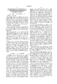
- FIG. 1 is a side view of an electrical component according to the invention
- FIG. 2 is a front view of the electrical component according to the invention.
- FIG. 3 shows a device for implementing the method for producing the aspiration surface on the component.
- an inductance coil 1 including an essentially cylindric main body 2 and leads 3 and 4.
- a planar aspiration surface 6 is formed on the main body 2 of the inductance coil 1 opposite a mounting side 5.
- the inductance coil 1 is therefore suited for being aspirated by suction tweezers (not shown) in a known manner, picked up and transported to a circuit board or the like, and precisely positioned.
- the inductance coils 1 are placed in a blister strip 8 comprised of several supply modules 10 in a known manner (e.g., by a shaker conveyor or a feeding screw) in the correct position and orientation.
- the blister strip 8 comprises a blister body 11 which includes depressions 12 for receiving the inductance coils 1.
- the blister strip 8 advances stepwise in the direction of the arrow 15.
- Apportioning means 20 are provided downstream thereof for the purpose of applying an adhesive mass 21 in a precisely controlled manner on the surface of the inductance coil 1 which is located opposite its mounting side 5.
- the amount of adhesive mass is selected to enable formation of a sufficiently large planar aspiration surface 6 on the inductance coil 1.
- the amount of adhesive mass 21 may vary depending on the configuration and size of the component.
- a transparent cover band 13 is placed over the inductance coils 1 and the adhesive mass 21 by means of a device 30.
- the device 30 can be a deflection roller for deflecting a cover band 13 which is supplied onto the blister strip 8 by a reel, for example.
- the cover band 13 is bonded to a respective inductance coil 1.
- the adhesive mass is cured with a curing device 50 by the application of radiation energy.
- a curing device 50 two co-operating elements of the curing device 50 provide a curing path with sufficient UV radiation to cure the adhesive mass.
- the cover band 13 is designed to transmit UV radiation.
- the cover band 13 is separated from the cured mass 21 on the inductance coil 1 by a stripping device 60.
- the stripping device 60 includes holding-down means 61 and stripping means 62. Between the holding-down means 61 and the stripping means 62, the cover band 13 is deflected upwardly with respect to the transport direction of the blister strip 8 and carried off.
- the design of stripping means 62 and holding-down means 61 ensures that the inductance coils 1 will not be lifted out of the blister strip 8.
- the mass 21 has already been cured at this point and maintains the configuration of a planar surface.
- the materials for the cover band 13 and for the adhesive mass 21 are selected such that the adhesive mass 21 will remain on the inductance coil 1 during stripping of the cover band 13 while only insubstantial residues appear on the cover band 13. Since the cover band 13 consists of transparent material, any residual mass 21 on the cover band 13 is perceivable and serves as a marking layer which indicates that the object present in the blister strip 8 has been obtained in accordance with the method of the invention and has a planar aspiration surface.
- a cover band application device 70 having the form of a reel is provided downstream.
- the cover band application device 70 reapplies the stripped cover band 13 onto the blister strip 8.
- Thermal bonding means 80 unite the cover band 13 with the blister strip 8 to effectively prevent the respective inductance coils 1 from dropping out during transport.
- the connection between cover band 13 and mass 21 having been neutralized by the stripping device 60, the inductance coils 1 are provided loosely in the depressions of the blister strip 8.
- the adhesive mass 21 may be cured with a suitable additive, in which case the curing device 50 can be omitted. It is also possible to omit the stripping device 60 and perform separation of cover band 13 and mass 21 immediately prior to mounting the inductance coils 1. It is further possible to utilize any other type of stripping device which can reliably separate the cover band 13 and the mass 21 without substantially impairing the planar configuration of the aspiration surface 6.
- another cover band may be arranged on the blister strip 8 with another feeding reel and the device 70. In this case, care should be taken that the cover band 13 is reliably carried off downstream from the stripping device 60.
- the design and control of the die 40 may be of any type as long as it is suited for shaping the mass 21 into a planar surface.
- the described method and the corresponding device may be employed with electrical components of various configurations and sizes. It is possible to utilize the method and the device in the mechanical arts for forming aspiration surfaces on small-size components, to facilitate their transport. Specific applications exist in the field of automated mechanical mounting. Finally, the invention may be used in conjunction with any type of object that requires a specific surface shape for safe and reliable grasping and transport, e.g., by suction tweezers or other customary tools in mounting technology.
- the adhesive mass can be made of material which may be liquefied, evaporated or volatilized during subsequent processing after mounting. Liquification or volatilization may be performed by heating the aspiration surface, resulting in liquification or evaporation of the adhesive mass while the solder or means of fixation of the component on a circuit board or in a system remains firm.
- the volatilizable or liquefiable material is wax, colophonium and/or plastic material which will volatilize or flow off at a solder-processing temperature (reflow soldering temperature) of, for example, 230° to 250° C. In this manner, the convolutions of a coil may be tuned following soldering.
- Volatizable or liquifiable material is also suited for movable mechanical components which are to be processed as SMD components. If the aspiration surface blocks the mobility of the mechanical component, the aspiration surface may be volatilized or liquefied by heating or irradiation.
- the supply modules can be provided by other known means, for example, with micropack feeders provided on reels.
- the device of the invention can be arranged in multiple parallel arrangement.
- the invention discloses a method and a device for producing an aspiration surface 6 on an object, preferably an electrical component intended for the SMD mounting technique.
- the invention furnishes an electrical component 1 comprising a planar aspiration surface 6 on the surface located opposite the mounting side 5.
- the aspiration surface 6 is formed by applying an adhesive mass 21 on the component 1, molding through a cover band 13 arranged above it with a die 40, and shaping the mass 21 into a planar surface. Following curing of the adhesive mass 21, the cover band 13 is separated from the mass 21 to provide a component 1 having a planar aspiration surface 6 which may readily be aspirated, picked up, and transported.
Landscapes
- Engineering & Computer Science (AREA)
- Microelectronics & Electronic Packaging (AREA)
- Power Engineering (AREA)
- Manufacturing & Machinery (AREA)
- Electric Connection Of Electric Components To Printed Circuits (AREA)
- Supply And Installment Of Electrical Components (AREA)
- Application Of Or Painting With Fluid Materials (AREA)
Applications Claiming Priority (2)
| Application Number | Priority Date | Filing Date | Title |
|---|---|---|---|
| DE29617668U | 1996-10-10 | ||
| DE29617668U DE29617668U1 (de) | 1996-10-10 | 1996-10-10 | Vorrichtung zur Herstellung einer Ansaugfläche auf einem Gegenstand und dadurch ausgebildetes elektrisches Bauteil |
Publications (1)
| Publication Number | Publication Date |
|---|---|
| US6042683A true US6042683A (en) | 2000-03-28 |
Family
ID=8030426
Family Applications (1)
| Application Number | Title | Priority Date | Filing Date |
|---|---|---|---|
| US08/948,423 Expired - Fee Related US6042683A (en) | 1996-10-10 | 1997-10-10 | Method and device for producing an aspiration surface on an object, and electrical component obtained thereby |
Country Status (3)
| Country | Link |
|---|---|
| US (1) | US6042683A (de) |
| EP (1) | EP0836372A3 (de) |
| DE (2) | DE29617668U1 (de) |
Cited By (4)
| Publication number | Priority date | Publication date | Assignee | Title |
|---|---|---|---|---|
| US20030200100A1 (en) * | 2002-04-18 | 2003-10-23 | Say-Yee Wen | Method and reminding assignment deadlines |
| US20040094330A1 (en) * | 2000-11-30 | 2004-05-20 | Jurgen Boy | Electrical component, arrangement for said component and method for producing said arrangement |
| US7564336B2 (en) | 2004-08-26 | 2009-07-21 | Cooper Technologies Company | Surface mount magnetic core with coil termination clip |
| US20160316592A1 (en) * | 2015-04-27 | 2016-10-27 | Panasonic Intellectual Property Management Co., Ltd. | Tape feeder and component mounting device |
Families Citing this family (4)
| Publication number | Priority date | Publication date | Assignee | Title |
|---|---|---|---|---|
| GB2320132A (en) * | 1996-12-04 | 1998-06-10 | Ibm | Handling electronic modules |
| DE19901962B4 (de) | 1999-01-19 | 2006-05-11 | Erni Elektroapparate Gmbh | Verfahren zum Montieren elektrischer Steckverbindungen sowie Montagehilfe zur Verfahrensdurchführung |
| DE19956828C2 (de) * | 1999-11-25 | 2003-02-13 | Vogt Electronic Ag | Modifizierter Ringkern zur Verwendung in einem elektromagnetischen Bauelement |
| DE102005022927A1 (de) † | 2005-05-13 | 2006-11-16 | Würth Elektronik iBE GmbH | Elektronisches Bauteil und Verfahren zu seiner Befestigung |
Citations (20)
| Publication number | Priority date | Publication date | Assignee | Title |
|---|---|---|---|---|
| DE3226733A1 (de) * | 1981-11-26 | 1983-07-07 | Softelec S.A., 1400 Yverdon | Integrierter schaltkreis |
| DE3507610A1 (de) * | 1984-03-05 | 1985-09-05 | Murata Manufacturing Co., Ltd., Nagaokakyo, Kyoto | Reihenanordnung bausteinfoermiger elektronischer komponenten |
| DE8604096U1 (de) * | 1986-02-15 | 1986-04-24 | Vogt Electronic Ag, 94130 Obernzell | Induktivität in SMD-Technik |
| DE3615307A1 (de) * | 1986-05-06 | 1987-11-12 | Johann Leonhard Huettlinger | Luftspulen fuer automatische smd-bestueckung |
| DE3736563A1 (de) * | 1986-10-30 | 1988-05-11 | Nitto System Technology Inc | Verfahren und vorrichtung zum entfernen eines abdeckbandelementes von einem chipband |
| DE3710184A1 (de) * | 1987-03-27 | 1988-10-13 | Siemens Ag | Elektrisches bauelement |
| DE3805572A1 (de) * | 1987-02-25 | 1989-02-02 | Tdk Corp | Traegerband fuer elektronische bauelemente sowie verfahren zum herstellen einer folge von elektronischen bauelementen |
| DE3806738C1 (de) * | 1988-03-02 | 1989-09-07 | Espe Stiftung & Co Produktions- Und Vertriebs Kg, 8031 Seefeld, De | |
| WO1990013135A1 (en) * | 1989-04-21 | 1990-11-01 | Motorola, Inc. | Improved surface-mountable air core inductor |
| WO1991018494A1 (de) * | 1990-05-23 | 1991-11-28 | Siemens Nixdorf Informationssysteme Aktiengesellschaft | Hilfsträger zum übertragen von teilen auf einen träger und verfahren zu dessen anwendung |
| DE4020305A1 (de) * | 1990-06-26 | 1992-01-09 | Siemens Ag | Spule zur oberflaechenmontage |
| DE4101790C1 (en) * | 1991-01-18 | 1992-07-09 | Technisch-Wissenschaftliche-Gesellschaft Thiede Und Partner Mbh, O-1530 Teltow, De | Chip-support arrangement prodn. - in tape form, in dual-in-line format by film-bond technology |
| DE4129146A1 (de) * | 1991-09-02 | 1993-03-04 | Siemens Nixdorf Inf Syst | Bandfoermiger hilfstraeger als montagehilfe fuer die zeilenweise montage von halbleiterchips auf einer passflaeche eines traegerelementes und ein zugehoeriges montageverfahren |
| EP0540497A2 (de) * | 1991-10-29 | 1993-05-05 | Alcatel Austria Aktiengesellschaft | Verfahren zur Herstellung fester Lotbeschichtungen |
| DE9410532U1 (de) * | 1994-06-29 | 1994-08-25 | Hagn Erwin | Elektrisches Bauteil, insbesondere Spule, vorzugsweise für SMD-Montagetechnik |
| EP0617437A1 (de) * | 1993-03-25 | 1994-09-28 | GRUNDIG E.M.V. Elektro-Mechanische Versuchsanstalt Max Grundig GmbH & Co. KG | Verfahren zum Abstimmen eines in SMD-Technik aufgebauten Schwingkreises |
| US5357077A (en) * | 1993-01-20 | 1994-10-18 | Nec Corporation | Apparatus for marking semiconductor devices |
| DE9420283U1 (de) * | 1994-12-19 | 1995-03-30 | Hagn Erwin | Elektrisches Bauteil, insbesondere Spule, vorzugsweise für SMD-Montagetechnik |
| DE4432909A1 (de) * | 1993-09-17 | 1995-03-30 | Mitsubishi Electric Corp | Artikelanordnungsvorrichtung |
| JPH0817602A (ja) * | 1994-06-24 | 1996-01-19 | Matsushita Electric Ind Co Ltd | 面実装部品 |
Family Cites Families (1)
| Publication number | Priority date | Publication date | Assignee | Title |
|---|---|---|---|---|
| US5383797A (en) * | 1993-07-08 | 1995-01-24 | Molex Incorporated | System for handling electrical connectors by a vacuum-suction nozzle |
-
1996
- 1996-10-10 DE DE29617668U patent/DE29617668U1/de not_active Expired - Lifetime
-
1997
- 1997-10-02 EP EP97117153A patent/EP0836372A3/de not_active Ceased
- 1997-10-08 DE DE19744455A patent/DE19744455A1/de not_active Ceased
- 1997-10-10 US US08/948,423 patent/US6042683A/en not_active Expired - Fee Related
Patent Citations (24)
| Publication number | Priority date | Publication date | Assignee | Title |
|---|---|---|---|---|
| DE3226733A1 (de) * | 1981-11-26 | 1983-07-07 | Softelec S.A., 1400 Yverdon | Integrierter schaltkreis |
| DE3507610A1 (de) * | 1984-03-05 | 1985-09-05 | Murata Manufacturing Co., Ltd., Nagaokakyo, Kyoto | Reihenanordnung bausteinfoermiger elektronischer komponenten |
| US4633370A (en) * | 1984-03-05 | 1986-12-30 | Murata Manufacturing Co., Ltd. | Chip-like electronic component series |
| DE8604096U1 (de) * | 1986-02-15 | 1986-04-24 | Vogt Electronic Ag, 94130 Obernzell | Induktivität in SMD-Technik |
| DE3615307A1 (de) * | 1986-05-06 | 1987-11-12 | Johann Leonhard Huettlinger | Luftspulen fuer automatische smd-bestueckung |
| DE3736563A1 (de) * | 1986-10-30 | 1988-05-11 | Nitto System Technology Inc | Verfahren und vorrichtung zum entfernen eines abdeckbandelementes von einem chipband |
| US4820369A (en) * | 1986-10-30 | 1989-04-11 | Nitto System Technology Inc. | Method for removing top tape element from chip tape and device therefor |
| DE3805572A1 (de) * | 1987-02-25 | 1989-02-02 | Tdk Corp | Traegerband fuer elektronische bauelemente sowie verfahren zum herstellen einer folge von elektronischen bauelementen |
| DE3710184A1 (de) * | 1987-03-27 | 1988-10-13 | Siemens Ag | Elektrisches bauelement |
| DE3806738C1 (de) * | 1988-03-02 | 1989-09-07 | Espe Stiftung & Co Produktions- Und Vertriebs Kg, 8031 Seefeld, De | |
| US4916805A (en) * | 1988-03-02 | 1990-04-17 | Espe Stiftung & Co. Produktions- Und Vertriebs Kg | Method for the attachment of components to a circuit board using photoactuatable adhesive |
| WO1990013135A1 (en) * | 1989-04-21 | 1990-11-01 | Motorola, Inc. | Improved surface-mountable air core inductor |
| WO1991018494A1 (de) * | 1990-05-23 | 1991-11-28 | Siemens Nixdorf Informationssysteme Aktiengesellschaft | Hilfsträger zum übertragen von teilen auf einen träger und verfahren zu dessen anwendung |
| DE4020305A1 (de) * | 1990-06-26 | 1992-01-09 | Siemens Ag | Spule zur oberflaechenmontage |
| DE4101790C1 (en) * | 1991-01-18 | 1992-07-09 | Technisch-Wissenschaftliche-Gesellschaft Thiede Und Partner Mbh, O-1530 Teltow, De | Chip-support arrangement prodn. - in tape form, in dual-in-line format by film-bond technology |
| DE4129146A1 (de) * | 1991-09-02 | 1993-03-04 | Siemens Nixdorf Inf Syst | Bandfoermiger hilfstraeger als montagehilfe fuer die zeilenweise montage von halbleiterchips auf einer passflaeche eines traegerelementes und ein zugehoeriges montageverfahren |
| EP0540497A2 (de) * | 1991-10-29 | 1993-05-05 | Alcatel Austria Aktiengesellschaft | Verfahren zur Herstellung fester Lotbeschichtungen |
| US5357077A (en) * | 1993-01-20 | 1994-10-18 | Nec Corporation | Apparatus for marking semiconductor devices |
| EP0617437A1 (de) * | 1993-03-25 | 1994-09-28 | GRUNDIG E.M.V. Elektro-Mechanische Versuchsanstalt Max Grundig GmbH & Co. KG | Verfahren zum Abstimmen eines in SMD-Technik aufgebauten Schwingkreises |
| DE4432909A1 (de) * | 1993-09-17 | 1995-03-30 | Mitsubishi Electric Corp | Artikelanordnungsvorrichtung |
| JPH0817602A (ja) * | 1994-06-24 | 1996-01-19 | Matsushita Electric Ind Co Ltd | 面実装部品 |
| DE9410532U1 (de) * | 1994-06-29 | 1994-08-25 | Hagn Erwin | Elektrisches Bauteil, insbesondere Spule, vorzugsweise für SMD-Montagetechnik |
| DE9420283U1 (de) * | 1994-12-19 | 1995-03-30 | Hagn Erwin | Elektrisches Bauteil, insbesondere Spule, vorzugsweise für SMD-Montagetechnik |
| WO1996019814A1 (de) * | 1994-12-19 | 1996-06-27 | Erwin Hagn | Elektrisches bauteil, insbesondere spule, vorzugsweise für smd-montagetechnik |
Non-Patent Citations (14)
| Title |
|---|
| EPP, pp. 36, "Neuer SMD-Bestueckungs-Vollautomat", Jul./Aug. 1992. |
| EPP, pp. 36, Neuer SMD Bestueckungs Vollautomat , Jul./Aug. 1992. * |
| Hartmut Michel, et al.,Siemens, vol. 3, pp. 1 4, MKT Kondensatoren in Tauchloebarer Chipbauform , 1985. * |
| Hartmut Michel, et al.,Siemens, vol. 3, pp. 1-4, "MKT-Kondensatoren in Tauchloebarer Chipbauform", 1985. |
| Patent Abstracts of Germany, DE 3 807 892, Jun. 1, 1994. * |
| Patent Abstracts of Germany, DE 3 938 718, May. 29, 1991. * |
| Patent Abstracts of Japan, vol. 17, No. 528 (E 1437), Sep. 22, 1993, JP 5 145283, Jun. 11, 1993. * |
| Patent Abstracts of Japan, vol. 17, No. 528 (E-1437), Sep. 22, 1993, JP 5-145283, Jun. 11, 1993. |
| Patent Abstracts of Japan, vol. 18, No. 507 (E 1609), Sep. 22, 1994, , JP 6 176927, Jun. 24, 1994. * |
| Patent Abstracts of Japan, vol. 18, No. 507 (E-1609), Sep. 22, 1994, , JP 6-176927, Jun. 24, 1994. |
| Rainer Rohm, Der Elektroniker, No. 2, pp. 27 32, SMD Bestueckungsautomat Fuer Leiterplatten Und Keramiksubstrate , 1986. * |
| Rainer Rohm, Der Elektroniker, No. 2, pp. 27-32, "SMD-Bestueckungsautomat Fuer Leiterplatten Und Keramiksubstrate", 1986. |
| Rolf D. Schraft, et al., Technische Rundschau, pp. 16 20, Stand der Technik Bei der SMT Bestueckung , 1988. * |
| Rolf D. Schraft, et al., Technische Rundschau, pp. 16-20, "Stand der Technik Bei der SMT-'Bestueckung", 1988. |
Cited By (6)
| Publication number | Priority date | Publication date | Assignee | Title |
|---|---|---|---|---|
| US20040094330A1 (en) * | 2000-11-30 | 2004-05-20 | Jurgen Boy | Electrical component, arrangement for said component and method for producing said arrangement |
| US7612294B2 (en) | 2000-11-30 | 2009-11-03 | Epcos Ag | Electrical component having a flat mounting surface |
| US20030200100A1 (en) * | 2002-04-18 | 2003-10-23 | Say-Yee Wen | Method and reminding assignment deadlines |
| US7564336B2 (en) | 2004-08-26 | 2009-07-21 | Cooper Technologies Company | Surface mount magnetic core with coil termination clip |
| US20160316592A1 (en) * | 2015-04-27 | 2016-10-27 | Panasonic Intellectual Property Management Co., Ltd. | Tape feeder and component mounting device |
| US10225970B2 (en) * | 2015-04-27 | 2019-03-05 | Panasonic Intellectual Property Management Co., Ltd. | Tape feeder and component mounting device |
Also Published As
| Publication number | Publication date |
|---|---|
| EP0836372A2 (de) | 1998-04-15 |
| DE29617668U1 (de) | 1996-12-05 |
| EP0836372A3 (de) | 1998-07-01 |
| DE19744455A1 (de) | 1998-04-16 |
Similar Documents
| Publication | Publication Date | Title |
|---|---|---|
| EP0615285A2 (de) | Montierung einer elektronischen Schaltung auf einem Substrat | |
| US6042683A (en) | Method and device for producing an aspiration surface on an object, and electrical component obtained thereby | |
| JP3606327B2 (ja) | 接点金属層を製造する方法および装置 | |
| US4314870A (en) | Method of mounting electronic components | |
| JP2504277B2 (ja) | 積層型セラミック電子部品用セラミックグリ―ンシ―トの製造方法および装置 | |
| EP0016368A1 (de) | Vorrichtung zum Befestigen von Komponenten | |
| US4934582A (en) | Method and apparatus for removing solder mounted electronic components | |
| US20080006922A1 (en) | Thermal release adhesive-backed carrier tapes | |
| KR970004751B1 (ko) | 프린트 회로판위에 표면장착형의 전자부품을 장착하는 방법 | |
| KR101994667B1 (ko) | 전자 부품 실장 장치 및 전자 부품의 제조 방법 | |
| EP0473911B1 (de) | Verfahren zur Montage von elektronischen Bauteilen auf einer Leiterplatte | |
| US6279814B1 (en) | Soldering apparatus for providing a fixed quantity of solder piece onto target plate | |
| JPS61500047A (ja) | 電子回路組立方法 | |
| US6082608A (en) | Solder bonding/debonding nozzle insert | |
| EP0376620A3 (de) | Verarbeitungsverfahren für mit Plastik umhüllte elektronische Anordnungen | |
| US4611092A (en) | Surface mount package for toroids | |
| US4968377A (en) | Method and apparatus for shaping cylindrical electrical parts | |
| EP0708586A1 (de) | Verfahren zum Fördern von Artikeln | |
| US20170203558A1 (en) | Apparatus and method for placing components on an electronic circuit | |
| JPH0481849B2 (de) | ||
| JPS6236630B2 (de) | ||
| US20040074581A1 (en) | Apparatus and method for assembling electronic components to a printed circuit board | |
| JPS5844794A (ja) | 回路基板に対するチツプ状部品のマウント方法 | |
| US6596566B2 (en) | Conformal-coated pick and place compatible devices | |
| JP3394667B2 (ja) | 半導体製造装置 |
Legal Events
| Date | Code | Title | Description |
|---|---|---|---|
| REMI | Maintenance fee reminder mailed | ||
| LAPS | Lapse for failure to pay maintenance fees | ||
| FP | Expired due to failure to pay maintenance fee |
Effective date: 20040328 |
|
| STCH | Information on status: patent discontinuation |
Free format text: PATENT EXPIRED DUE TO NONPAYMENT OF MAINTENANCE FEES UNDER 37 CFR 1.362 |