US5889367A - Long-life high powered excimer lamp with specified halogen content, method for its manufacture and extension of its burning life - Google Patents
Long-life high powered excimer lamp with specified halogen content, method for its manufacture and extension of its burning life Download PDFInfo
- Publication number
- US5889367A US5889367A US08/832,281 US83228197A US5889367A US 5889367 A US5889367 A US 5889367A US 83228197 A US83228197 A US 83228197A US 5889367 A US5889367 A US 5889367A
- Authority
- US
- United States
- Prior art keywords
- discharge chamber
- halogen
- lamp
- excimer lamp
- excimer
- Prior art date
- Legal status (The legal status is an assumption and is not a legal conclusion. Google has not performed a legal analysis and makes no representation as to the accuracy of the status listed.)
- Expired - Lifetime
Links
Images


Classifications
-
- H—ELECTRICITY
- H01—ELECTRIC ELEMENTS
- H01J—ELECTRIC DISCHARGE TUBES OR DISCHARGE LAMPS
- H01J61/00—Gas-discharge or vapour-discharge lamps
- H01J61/70—Lamps with low-pressure unconstricted discharge having a cold pressure < 400 Torr
-
- H—ELECTRICITY
- H01—ELECTRIC ELEMENTS
- H01J—ELECTRIC DISCHARGE TUBES OR DISCHARGE LAMPS
- H01J61/00—Gas-discharge or vapour-discharge lamps
- H01J61/02—Details
- H01J61/12—Selection of substances for gas fillings; Specified operating pressure or temperature
Definitions
- the invention relates to an improved excimer lamp of the type with a discharge chamber usually of quartz or ceramic, and which holds a halogen-containing filling gas forming excimers under discharge conditions.
- the invention also relates to a method for the manufacture of a long-life excimer lamp; a method for extending the burning life of such an excimer lamp; and a device for practicing the latter method.
- Excimer lamps are used for generating high-energy ultraviolet radiation.
- the excimer radiation is also described as silent electrical discharge. This is generated in a discharge chamber bound by dielectrics in which the filling gas forming the excimers is contained.
- An excimer lamp of the specified type is known from EP-A1 0 547 366.
- a variety of noble gases are proposed as filling gases depending on the desired spectral composition of the radiation, for example, argon, krypton or xenon or noble gas mixtures, respectively, which, for example, contain chlorine or a chlorine-containing compound from which one or more chlorine atoms are expelled during the discharge.
- an excimer lamp which is developed as a planar flatform lamp.
- the discharge chamber contains a halogen-containing noble gas filling, whereby the partial pressure of the halogen is between 0.05% and 5% of the partial pressure of the noble gas.
- the known excimer lamp is characterized by a high radiation intensity.
- the maximally adjustable ultraviolet radiation intensity already decreases within the first 300 hours of operation.
- the drop in the ultraviolet radiation intensity is typically greater than 50% of the initial radiation intensity.
- EP-A1 607 960 An attempt to extend the burning life of a lamp of this type is described in EP-A1 607 960.
- an excimer lamp is described which features a discharge chamber which is sealed in a gas-proof fashion and is filled with a suitable filling gas.
- EP-A 1607960 teaches the proposed elimination of gaseous impurities in the filling gas and to that end provide a "getter" which may be disposed inside the discharge chamber or in connection with it.
- eliminating filling gas impurities is not sufficient for a marked increase in-burning life.
- a further object of the invention is to provide a method for extending the burning life of excimer lamps and a device suitable to practice this method.
- the object of the invention is attained with an improvement to the above mentioned excimer lamp by using a halogen content in the discharge chamber of at least of 1 ⁇ 10 -10 mol/cm 3 volume of the chamber for each cm 2 of area of the interior surface of the discharge chamber and, simultaneously, being set as a function of the maximum power density of the lamp, expressed in the unit "watt per cm of lamp length," at a value in the range of 1 ⁇ 10 -7 mol/cm 3 to 1 ⁇ 10 -5 mol/cm 3 per unit of power density.
- FIG. 1 a creep diagram for various XeCl excimer lamps
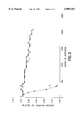
- FIG. 2 a creep diagram for KrCl excimer lamps with high power
- FIG. 3 a creep diagram for KrCl excimer lamps with low power
- FIG. 4 a section from an excimer lamp with a halogen reservoir in the discharge chamber in longitudinal view schematically represented.
- halogen refers to fluorine, chlorine, bromine and iodine as well as mixtures of these gases;
- non-ble gas refers to helium, neon, argon, krypton and xenon as well as mixtures of these gases. If the filling gas contains compounds which release halogens under discharge conditions, the halogen concentrations actually released under discharge conditions are of significance for determining the amount of halogen. It has been demonstrated that the releasing of halogen essentially depends on the power density at which the lamp is operated.
- the present invention provides an improvement to known excimer lamps in order to extend their life by restraining the drop in UV intensity caused by the loss of halogen.
- the loss of halogen can be the result of a reaction of the halogen with the interior surfaces of the discharge chamber.
- the boundary walls of the discharge chamber can, for example, consist of quartz glass or of a ceramic material.
- the surface reaction of the halogen can be avoided by means of a suitable modification of the interior surfaces delimiting the discharge chamber, such measures are labor-intensive and expensive and, moreover, the modifications made are often not sufficiently resistant to the discharge. For example, protective layers which were applied may flake off.
- This invention is based in part on the discovery that the saturation concentration per cm 2 of the interior surface of the discharge chamber is at a halogen content of at least 1 ⁇ 10 -10 mol/cm 3 of the chamber volume.
- This halogen content can be measured in the filling gas prior to the occurrence of surface reactions with halogen, e.g. prior to the initial operation of the lamp.
- the halogen content in the discharge chamber can be determined by adding any halogen bonded to or in the interior surface of the discharge chamber to the halogen content of the filling gas.
- the determination of the halogen content bonded to or in the interior surface of the discharge chamber can, for example, take place through release of the halogen in the discharge chamber by means of a suitable temperature treatment.
- this halogen content can also be determined via chemical or spectroscopic methods. In doing so, however, it must be noted that such halogen, which might additionally be present inside the material of the walls delimiting the discharge chamber, is not taken into account.
- synthetic quartz glass often contains a certain chlorine content which is a function of the manufacturing method. If the indicated saturation concentration of halogens in the discharge chamber can be permanently maintained, a decrease in the radiation intensity is prevented totally or partially over time. A concentration of halogen exceeding the actually sufficient saturation concentration has no damaging effects on the burning life behavior.
- the halogen concentration to be set also depends on the maximum power density of he lamp.
- an additional proportioning rule must be observed, namely that the halogen content in the discharge chamber is set as a function of the maximum power density of the lamp, expressed in the unit "watt per cm of lamp length,” at a value in the range of 1 ⁇ 10 -7 mol/cm 3 to 1 ⁇ 10 -5 mol/cm 3 per unit of power density.
- the indicated interrelationship between the power density and the appropriate halogen content of the discharge chamber has proven to be basically linear up to a power density of approximately 200 W/cm of length of lamp. It can be assumed that this interrelationship is also valid with even higher power densities, for example, with power densities around 400 W/cm.
- length of lamp refers only to the length of the lamp actually illuminated.
- the halogen concentration can be adjusted to a relatively high level. And, vice versa, if a high power density is more important than a particularly long burning life, the halogen concentration can be kept relatively low.
- the specified saturation concentration corresponds approximately to a mixing ratio of halogen:noble gas of 1:50 to 1:500.
- These mixing ratios are only given as reference points to facilitate orientation.
- not the mixing ratio but the absolute halogen content, in terms of the size of the interior surface and the volume of the discharge chamber, is decisive for the excimer lamp according to the invention.
- possible buffer gases in the discharge chamber which can also be noble gases, are not taken into consideration.
- an excimer lamp in which the halogen content of the discharge chamber is in the range of about 1 ⁇ 10 -10 mol/cm 3 to about 1 ⁇ 10 -8 mol/cm 3 per cm 2 of its interior surface area.
- the upper limit follows from the decreasing efficiency of the lamp with increasing halogen content.
- Halogen possesses a high electro-negativity and generally a lower excitation probability with respect to the noble gas. Therefore, as is known in the art, it catches a relatively large quantity of electrons and the lamp can only be lit with difficulty with a high chlorine content.
- the filament density increases and, as a result, the halogen content in its atomic form.
- Atomic halogen attaches particularly easily to the boundary walls of the discharge chamber.
- the specified upper limit for halogen concentration is thus of particular significance for excimer lamps with a high power density of around 100 W per cm of lamp length, whereas for excimer lamps with lower power density--irrespective of the above proportioning rule with regard to power density--this upper limit can be reduced somewhat for the above cited reasons.
- An excimer lamp in which the filling gas contains chlorine or a compound releasing chlorine under discharge conditions has a particularly long burning life.
- a suitable chlorine-containing filling gas contains, for example, HCl with 2% Cl 2 and a noble gas, such as krypton, xenon or argon.
- An excimer lamp in which a halogen-containing reservoir is disposed in the discharge chamber, whereby the concentration of halogen in the reservoir exceeds that in the filling gas, has proved particularly advantageous.
- the halogen in the halogen reservoir is separated from the filling gas of the discharge chamber. If the halogen content drops below a given lower limit, the reservoir can be opened automatically or manually, thus releasing the halogen contained in it to the discharge chamber.
- the halogen content of the reservoir is calculated such that through release, the concentration of halogen in the discharge chamber can be increased, for example, so that the desired concentration of halogen in the discharge chamber can be obtained.
- a suitable halogen content of the reservoir thus follows simply from the difference between the concentration at the lower limit and the desired concentration as well as the volume of the discharge chamber.
- the reservoir has a relatively low volume, compared with the volume of the discharge chamber.
- the halogen concentration in the reservoir is thus relatively high.
- the reservoir can, for example, be designed in the form of a chamber made of quartz glass or a ceramic material which, upon reaching the mentioned lower limit of the concentration, is broken.
- the lower limit of the concentration can be determined on the basis of intensity measurements of the excimer radiation.
- the above indicated object is met according to the invention proceeding from the initially specified method, by treating the interior surfaces of the discharge chamber with a halogen-containing passivating gas prior to filling in the filling gas.
- This passivation is a modification of the interior surface of the discharge chamber which can be performed relatively easily. For example, it can take place simply by rinsing or flushing the discharge chamber with halogen.
- the method according to the invention has proven particularly effective with respect to an extension of the burning life of excimer lamps in which chlorine or a compound releasing chlorine under discharge conditions is employed, if chlorine is used for the passivation.
- the halogen content of the passivating gas per each cm 2 of area of the interior surface of the discharge chamber is advantageously at least 1 ⁇ 10 -10 mol/cm 3 , provided that it is selected to be at least as large as the halogen content in the filling gas.
- the term "halogen content” is understood as the concentration of halogen with respect to the volume of the discharge chamber.
- the passivation can be performed with discharge chamber walls made of quartz glass at an increased temperature of up to 1000° C.; and with ceramic walls at even higher temperatures.
- the present invention also provides a method for extending the burning life of an excimer lamp, by exposing the discharge chamber to infrared radiation or by releasing halogen from a halogen reservoir disposed in the discharge chamber.
- the walls delimiting the discharge chamber are heated preferably using infrared radiation.
- the walls generally are made of quartz glass. It was discovered that the heating will reverse a previously occurring depletion of halogen from the filling gas. It was previously assumed that halogen is fully absorbed by the quartz glass or forms a stable chemical compound with the silicon of the quartz glass. The inventors hereof discovered that the take-up of halogen by the walls of the lamp is reversible and that, by reversing the take-up and releasing the halogen, the burning life of the lamp is extended.
- the filling gas can be regenerated with respect to its halogen content.
- the loss of halogen that has occurred has so far been shown to be reversible.
- the reversibility of the loss of halogen is concomitant with an extension of the burning life of the excimer lamp.
- the temporary loss of halogen within the discharge chamber and operation with low halogen content do not result in irreversible damage to the excimer lamp.
- the excimer lamp can, for example, be placed in an oven, or it is exposed to radiation emitted by an infrared lamp.
- the halogen is released from a halogen reservoir disposed in the discharge chamber.
- the concentration of the halogen in the reservoir is set higher than that in the filling gas.
- the additional halogen from the reservoir can compensate for a loss of halogen in the discharge chamber. If the halogen content drops below a given lower limit, the reservoir can be opened automatically or manually, thus releasing the halogen contained in it to the discharge chamber.
- a method has proved particularly advantageous in which the discharge chamber is heated to a temperature in the range of 400° C. to 1000° C., preferably by means of infrared radiation.
- This temperature range applies to a discharge chamber with boundary walls of quartz glass. If the boundary walls are made of ceramic material, such as Al 2 O 3 , temperatures above 1000° C. are more favorable.
- Such a method has proven particularly effective with chlorine-containing filling gas.
- the above indicated object is met according to the invention by providing at least one infrared lamp which is disposed adjacent to the excimer lamp in such a manner that the infrared radiation emanating from the infrared lamp heats the discharge chamber.
- the above explained method for extending the burning life of the excimer lamp can be applied at any time in a simple fashion. For this, only the infrared lamp need be switched on. In doing so, the infrared radiation is directed at the discharge chamber and heats its boundary walls. Thus the halogen taken-up on the walls is released.
- an oven is also basically suitable.
- the infrared source lamp is provided with a reflector which directs the infrared radiation at the discharge chamber and thus prevents undesired infrared radiation in other directions.
- the length of the infrared lamp or the total length of all infrared lamps corresponds approximately to the length of the discharge chamber. This enables the halogen to be effectively released across the total length of the discharge chamber.
- the infrared lamp or infrared lamps run parallel to the discharge chamber of an excimer lamp.
- a device in which at least one infrared lamp and the excimer lamp are electrically connected with each other in such a manner that after a determinable time interval prior or subsequent to switching on the excimer lamp, the infrared lamp is switched on.
- This embodiment of the device has the advantage that the release of the halogens from the interior surfaces delimiting the discharge chamber takes place in a reproducible manner. In doing so, the excimer lamp and the infrared lamp can be switched on simultaneously, e.g. the above mentioned interval can also be 0.
- FIG. 1 shows the burning life behavior of a XeCl module lamps. They generate a power density of 25 W/cm of length of lamp.
- the filling pressure of the filling gas in the discharge chamber is 750 mbar.
- Argon as buffer gas contributes approximately 300 mbar to this internal pressure.
- the discharge chamber in these lamps is formed by the clearance between two quartz glass tubes which run coaxially with respect to each other.
- the outer diameter of the discharge chamber is 27 mm, the inner diameter 16 mm and the length 343 mm.
- the curve designated with the reference number 1 reflects the burning life behavior of a XeCl module lamp commercially available currently.
- the mixing ratio of xenon to chlorine is approximately 1000:1.
- the absolute chlorine content in the discharge chamber is below 1 ⁇ 10 -10 mol/cm 3 per cm 2 of the interior surface of the discharge chamber; more precisely at approximately 3 ⁇ 10 -11 mol/cm 3 .
- the interior surface of the discharge chamber is approximately 470 cm 2 .
- concentration refers in this context to the volume of the discharge chamber.
- the progression of the curve designated with the reference number 2 reflects the burning life behavior of a XeCl module lamp in which the chlorine content of the discharge chamber is quintupled compared to the previously described known excimer lamp.
- the mixing ratio of xenon to chloride consequently is approximately 200:1. From the above indications a chlorine content of 1.5 ⁇ 10 -10 mol/cm 3 per cm 2 of the interior surface of the discharge chamber results.
- the power density is approximately 30 watts per cm of illuminated length of lamp.
- the examined XeCl module lamps are identical.
- the chlorine attaches to the interior walls of the discharge chamber; thus, in the filling gas, the chlorine content slowly decreases and, in doing so, can drop below the value of, for example, 5 ⁇ 10 -11 mol/cm 3 cm 2 of the interior surface.
- the burning life behavior of the XeCl module lamp according to the invention is characterized by an only slight and particularly slow decrease of the UVB radiation intensity over time. After approximately 1000 hours of operation, the relative UVB radiation intensity has only decreased by approximately 20%. However, it cannot be determined from curve 2 if the radiation intensity results in a final value.
- KrCl module lamps represented in FIG. 2. These generate a power density of 25 W/cm of length of lamp.
- the filling pressure of the filling gas in the discharge chamber is 350 mbar.
- the discharge chamber in these lamps is also formed by the clearance of two quartz glass tubes which run coaxially with respect to each other.
- the outer diameter of the discharge chamber is 27 mm, the inner diameter 16 mm and the length 343 mm.
- curve 3 is a creep curve as it is generally measured with a KrCl module lamp according to the state of the art.
- the mixing ratio of krypton to chlorine is approximately 1000:1.
- the absolute chlorine content in this lamp is identical to the one in the above described known XeCl module lamp.
- a relatively significant decrease of the UVC radiation intensity can be observed which ends after approximately 300 to 400 hours of operation at a low final value which is below 10% of the original radiation intensity.
- Curves 4 and 5 show results for to KrCl module lamps which differ only with respect to the mixing ratio of the filling gas. They generate a power density of 25 W/cm of length of lamp. Here, a buffer gas is not present.
- the initial mixing ratio of krypton:chlorine is 100:1, in the creep curve 5, 50:1.
- the last mentioned mixing ratio corresponds to a chlorine content of approximately 6 ⁇ 10 -10 mol/cm 3 per cm 2 of the interior surface of the discharge chamber.
- the interior surface of the discharge chamber is approximately 470 cm 2 .
- each creep curve 4 and 5 is marked by an initial light increase in the UVC radiation intensity, which terminates after several hours of operation in a high and constant final value, which is dependent on the chlorine concentration. A decrease in radiation intensity could not be observed with the KrCl module lamp according to the invention even after 1000 hours of operation.
- the creep curve designated with the reference number 6 again reflects the typical burning life progression of commercially available excimer lamps, whereby subsequent to an initial heavy drop in the UVC radiation intensity after approximately 350 hours of operation, a final value for the radiation intensity on a low level is achieved.
- the latter was evacuated, then filled with chlorine at ambient temperature which, after approximately 3 seconds, was again pumped off. Subsequently, the discharge chamber was filled with filling gas and sealed in a gas-proof fashion.
- the KrCl excimer lamp according to the invention showed only a slight decrease in the UVC radiation intensity during the test time of approximately 2000 hours.
- a thermal treatment at a temperature of 750° C. over a period of time of one hour.
- the excimer lamp schematically represented in FIG. 4 is referred to in its entirety with reference number 11.
- the excimer lamp 11 consists of an outer quartz glass tube 12, which is covered with a metallic net 13 on its jacket surface, which forms the outer electrode of the excimer lamp 11, and an inner quartz glass tube 14 which is disposed so as to be coaxial with the outer quartz glass tube 12 and against whose inner wall a metallic spiral 15 rests which forms the inner electrode of the excimer lamp 11.
- the annular gap between the outer quartz glass tube 12 and the inner quartz glass tube 14 corresponds to the discharge chamber 16 of the excimer lamp 11.
- the volume of the discharge chamber 16 is approximately 470 cm 3 .
- the power density is at 30 watts per cm illuminated length of lamp.
- a quartz glass capsule 17 filled with chlorine is disposed in the discharge chamber 16 .
- the wall of capsule 17 is scratched and provided in this manner with a desired breaking point 18.
- the chlorine content of capsule 17 is set such that after breaking capsule 17 the chlorine content in the discharge chamber 16 is increased, namely, by 1 ⁇ 10 11 mol/cm 3 per each cm 2 of the interior surface of discharge chamber 16.
- a metal component 19 is embedded and shielded from discharge chamber 16.
- the metal component 19 together with the capsule 17 is maintained in an upper position by means of magnet 20. If the capsule 17 is dropped from this position, e.g. by removing or switching off the magnet, the capsule 17 breaks and the chlorine contained in it escapes into the discharge chamber 16. In this manner, the chlorine content in discharge chamber 16 can be regenerated.
- the intensity of a characteristic emission wavelength of the excimer lamp 11 is measured with an ultraviolet sensor. If the lower limit of intensity is surpassed, this is visually indicated and the magnet 20 is then removed.
- magnet 20 is developed as an electromagnet, magnet 20 is automatically switched off when the lower limit of the intensity is surpassed and thereby the chlorine from capsule 17 is released into discharge chamber 16.
Landscapes
- Vessels And Coating Films For Discharge Lamps (AREA)
- Discharge Lamps And Accessories Thereof (AREA)
- Lasers (AREA)
- Discharge Lamp (AREA)
- Treatments Of Macromolecular Shaped Articles (AREA)
Applications Claiming Priority (2)
| Application Number | Priority Date | Filing Date | Title |
|---|---|---|---|
| DE19613502A DE19613502C2 (de) | 1996-04-04 | 1996-04-04 | Langlebiger Excimerstrahler und Verfahren zu seiner Herstellung |
| DE19613502.8 | 1996-04-04 |
Publications (1)
| Publication Number | Publication Date |
|---|---|
| US5889367A true US5889367A (en) | 1999-03-30 |
Family
ID=7790468
Family Applications (1)
| Application Number | Title | Priority Date | Filing Date |
|---|---|---|---|
| US08/832,281 Expired - Lifetime US5889367A (en) | 1996-04-04 | 1997-04-03 | Long-life high powered excimer lamp with specified halogen content, method for its manufacture and extension of its burning life |
Country Status (4)
| Country | Link |
|---|---|
| US (1) | US5889367A (de) |
| EP (1) | EP0800201B1 (de) |
| JP (1) | JP4004590B2 (de) |
| DE (2) | DE19613502C2 (de) |
Cited By (18)
| Publication number | Priority date | Publication date | Assignee | Title |
|---|---|---|---|---|
| US5993278A (en) * | 1998-02-27 | 1999-11-30 | The Regents Of The University Of California | Passivation of quartz for halogen-containing light sources |
| US6342761B1 (en) | 1998-12-08 | 2002-01-29 | Heraeus Noblelight Gmbh | Discharge lamp having an internal electrode formed of a spiral band |
| US6421503B2 (en) | 2000-05-22 | 2002-07-16 | Heraeus Noblelight Gmbh | Infrared radiation system with multiple IR radiators of different wavelength |
| US20020190227A1 (en) * | 2001-06-14 | 2002-12-19 | Photoscience Japan Corporation | Discharge lamp, ultraviolet ray irradiation apparatus and method of using the apparatus |
| US6534904B1 (en) * | 1999-03-19 | 2003-03-18 | Heraeus Noblelight Gmbh | Infrared lamp with carbon ribbon being longer than a radiation length |
| US20050199484A1 (en) * | 2004-02-10 | 2005-09-15 | Franek Olstowski | Ozone generator with dual dielectric barrier discharge and methods for using same |
| WO2006017644A2 (en) * | 2004-08-03 | 2006-02-16 | Franek Olstowski | Improved closed-loop light intensity control and related fluorescence application method |
| WO2007071074A1 (en) * | 2005-12-21 | 2007-06-28 | Trojan Technologies Inc. | Excimer radiation lamp assembly, and source module and fluid treatment system containing same |
| US20080093967A1 (en) * | 2004-07-09 | 2008-04-24 | Koninklijke Philips Electronics, N.V. | Dielectric Barrier Discharge Lamp With Integrated Multifunction Means |
| US20080197775A1 (en) * | 2005-02-14 | 2008-08-21 | Patent Treuhand Gesellschaft Fur Elektrische Gluhlampen Mbh | Dielectric Barrier Discharge Lamp Configured as a Double Tube |
| CN101859687A (zh) * | 2009-04-10 | 2010-10-13 | 优志旺电机株式会社 | 准分子放电灯 |
| US20100259170A1 (en) * | 2009-04-10 | 2010-10-14 | Ushio Denki Kabushiki Kaisha | Excimer discharge lamp |
| TWI417933B (zh) * | 2007-09-20 | 2013-12-01 | Ushio Electric Inc | Method for manufacturing excimer lamp and excimer lamp |
| US8754576B2 (en) | 2012-09-28 | 2014-06-17 | Elwha Llc | Low pressure lamp using non-mercury materials |
| RU2546144C2 (ru) * | 2013-07-25 | 2015-04-10 | Федеральное государственное бюджетное учреждение науки Институт сильноточной электроники Сибирского отделения Россиийской академии наук, (ИСЭ СО РАН) | Источник излучения |
| RU200241U1 (ru) * | 2019-12-19 | 2020-10-14 | Федеральное государственное бюджетное учреждение науки Институт сильноточной электроники Сибирского отделения Российской академии наук, (ИСЭ СО РАН) | Источник излучения |
| CN113611591A (zh) * | 2020-08-28 | 2021-11-05 | 优志旺电机株式会社 | 准分子灯 |
| US11501963B2 (en) | 2020-08-28 | 2022-11-15 | Ushio Denki Kabushiki Kaisha | Excimer lamp and light irradiation device |
Families Citing this family (3)
| Publication number | Priority date | Publication date | Assignee | Title |
|---|---|---|---|---|
| JP5302637B2 (ja) * | 2008-11-17 | 2013-10-02 | 株式会社オーク製作所 | 放電ランプ |
| WO2012110074A1 (de) * | 2011-02-14 | 2012-08-23 | Osram Ag | Hochdruckentladungslampe mit halogenhalteriger zündhilfe |
| JP2014049280A (ja) * | 2012-08-31 | 2014-03-17 | Ushio Inc | エキシマランプ |
Citations (16)
| Publication number | Priority date | Publication date | Assignee | Title |
|---|---|---|---|---|
| US4870323A (en) * | 1988-07-13 | 1989-09-26 | Gte Products Corporation | Method of dispensing mercury into an arc discharge lamp |
| EP0344732A1 (de) * | 1988-06-03 | 1989-12-06 | Forschungszentrum Jülich Gmbh | Metallhalogenid-Entladungslampen |
| DE3935084A1 (de) * | 1988-10-20 | 1990-04-26 | Mitsubishi Electric Corp | Verfahren und geraet zur gasregulierung in einem halogengaslaser |
| US4945290A (en) * | 1987-10-23 | 1990-07-31 | Bbc Brown Boveri Ag | High-power radiator |
| DE3907277A1 (de) * | 1989-03-07 | 1990-09-20 | Patent Treuhand Ges Fuer Elektrische Gluehlampen Mbh | Quecksilberniederdruckentladungslampe |
| US4977573A (en) * | 1989-03-09 | 1990-12-11 | Questek, Inc. | Excimer laser output control device |
| US5006758A (en) * | 1988-10-10 | 1991-04-09 | Asea Brown Boveri Ltd. | High-power radiator |
| EP0457745A2 (de) * | 1990-05-17 | 1991-11-21 | Potomac Photonics, Inc. | Halogenverträgliche Hochfrequenzentladungsvorrichtung |
| US5173638A (en) * | 1986-07-22 | 1992-12-22 | Bbc Brown, Boveri Ag | High-power radiator |
| EP0521553A2 (de) * | 1991-07-01 | 1993-01-07 | Koninklijke Philips Electronics N.V. | Hochdrucksglimmentladungslampe |
| US5194740A (en) * | 1991-04-15 | 1993-03-16 | Asea Brown Boveri Ltd. | Irradiation device |
| EP0547366A1 (de) * | 1991-12-09 | 1993-06-23 | Heraeus Noblelight GmbH | Hochleistungsstrahler |
| DE3910809C2 (de) * | 1989-04-04 | 1994-02-17 | Werner Reinig | Anordnung zum Gleichstrombetrieb einer Leuchtstofflampe |
| EP0607960A1 (de) * | 1993-01-20 | 1994-07-27 | Ushiodenki Kabushiki Kaisha | Entladungslampe mit dielektrischer Sperrschicht |
| EP0641015A2 (de) * | 1993-08-03 | 1995-03-01 | Ushiodenki Kabushiki Kaisha | Cadmiumentladungslampe |
| US5432398A (en) * | 1992-07-06 | 1995-07-11 | Heraeus Noblelight Gmbh | High-power radiator with local field distortion for reliable ignition |
Family Cites Families (1)
| Publication number | Priority date | Publication date | Assignee | Title |
|---|---|---|---|---|
| JP3076392B2 (ja) * | 1991-03-29 | 2000-08-14 | 株式会社東芝 | エキシマレーザ装置の不動態化処理方法 |
-
1996
- 1996-04-04 DE DE19613502A patent/DE19613502C2/de not_active Expired - Fee Related
-
1997
- 1997-03-27 EP EP97105297A patent/EP0800201B1/de not_active Expired - Lifetime
- 1997-03-27 DE DE59702367T patent/DE59702367D1/de not_active Expired - Lifetime
- 1997-04-02 JP JP08346997A patent/JP4004590B2/ja not_active Expired - Lifetime
- 1997-04-03 US US08/832,281 patent/US5889367A/en not_active Expired - Lifetime
Patent Citations (17)
| Publication number | Priority date | Publication date | Assignee | Title |
|---|---|---|---|---|
| US5173638A (en) * | 1986-07-22 | 1992-12-22 | Bbc Brown, Boveri Ag | High-power radiator |
| US4945290A (en) * | 1987-10-23 | 1990-07-31 | Bbc Brown Boveri Ag | High-power radiator |
| EP0344732A1 (de) * | 1988-06-03 | 1989-12-06 | Forschungszentrum Jülich Gmbh | Metallhalogenid-Entladungslampen |
| US4870323A (en) * | 1988-07-13 | 1989-09-26 | Gte Products Corporation | Method of dispensing mercury into an arc discharge lamp |
| US5006758A (en) * | 1988-10-10 | 1991-04-09 | Asea Brown Boveri Ltd. | High-power radiator |
| DE3935084A1 (de) * | 1988-10-20 | 1990-04-26 | Mitsubishi Electric Corp | Verfahren und geraet zur gasregulierung in einem halogengaslaser |
| DE3907277A1 (de) * | 1989-03-07 | 1990-09-20 | Patent Treuhand Ges Fuer Elektrische Gluehlampen Mbh | Quecksilberniederdruckentladungslampe |
| US4977573A (en) * | 1989-03-09 | 1990-12-11 | Questek, Inc. | Excimer laser output control device |
| DE3910809C2 (de) * | 1989-04-04 | 1994-02-17 | Werner Reinig | Anordnung zum Gleichstrombetrieb einer Leuchtstofflampe |
| EP0457745A2 (de) * | 1990-05-17 | 1991-11-21 | Potomac Photonics, Inc. | Halogenverträgliche Hochfrequenzentladungsvorrichtung |
| US5194740A (en) * | 1991-04-15 | 1993-03-16 | Asea Brown Boveri Ltd. | Irradiation device |
| EP0521553A2 (de) * | 1991-07-01 | 1993-01-07 | Koninklijke Philips Electronics N.V. | Hochdrucksglimmentladungslampe |
| EP0547366A1 (de) * | 1991-12-09 | 1993-06-23 | Heraeus Noblelight GmbH | Hochleistungsstrahler |
| US5386170A (en) * | 1991-12-09 | 1995-01-31 | Heraeus Noblelight Gmbh | High-power radiator |
| US5432398A (en) * | 1992-07-06 | 1995-07-11 | Heraeus Noblelight Gmbh | High-power radiator with local field distortion for reliable ignition |
| EP0607960A1 (de) * | 1993-01-20 | 1994-07-27 | Ushiodenki Kabushiki Kaisha | Entladungslampe mit dielektrischer Sperrschicht |
| EP0641015A2 (de) * | 1993-08-03 | 1995-03-01 | Ushiodenki Kabushiki Kaisha | Cadmiumentladungslampe |
Cited By (30)
| Publication number | Priority date | Publication date | Assignee | Title |
|---|---|---|---|---|
| US5993278A (en) * | 1998-02-27 | 1999-11-30 | The Regents Of The University Of California | Passivation of quartz for halogen-containing light sources |
| US6342761B1 (en) | 1998-12-08 | 2002-01-29 | Heraeus Noblelight Gmbh | Discharge lamp having an internal electrode formed of a spiral band |
| US6765339B2 (en) * | 1999-03-19 | 2004-07-20 | Heraeus Noblelight Gmbh | Infrared lamp and procedure for heating material to be processed |
| US6534904B1 (en) * | 1999-03-19 | 2003-03-18 | Heraeus Noblelight Gmbh | Infrared lamp with carbon ribbon being longer than a radiation length |
| US6421503B2 (en) | 2000-05-22 | 2002-07-16 | Heraeus Noblelight Gmbh | Infrared radiation system with multiple IR radiators of different wavelength |
| US6577816B2 (en) | 2000-05-22 | 2003-06-10 | Heraeus Noblelight Gmbh | Infrared radiation system with multiple IR radiators of different wavelength |
| US6683411B2 (en) * | 2001-06-14 | 2004-01-27 | Photoscience Japan Corporation | Discharge lamp, ultraviolet ray irradiation apparatus and method of using the apparatus |
| US20020190227A1 (en) * | 2001-06-14 | 2002-12-19 | Photoscience Japan Corporation | Discharge lamp, ultraviolet ray irradiation apparatus and method of using the apparatus |
| US20050199484A1 (en) * | 2004-02-10 | 2005-09-15 | Franek Olstowski | Ozone generator with dual dielectric barrier discharge and methods for using same |
| US7675237B2 (en) * | 2004-07-09 | 2010-03-09 | Koninklijke Philips Electronics N.V. | Dielectric barrier discharge lamp with integrated multifunction means |
| US20080093967A1 (en) * | 2004-07-09 | 2008-04-24 | Koninklijke Philips Electronics, N.V. | Dielectric Barrier Discharge Lamp With Integrated Multifunction Means |
| WO2006017644A2 (en) * | 2004-08-03 | 2006-02-16 | Franek Olstowski | Improved closed-loop light intensity control and related fluorescence application method |
| WO2006017644A3 (en) * | 2004-08-03 | 2006-06-29 | Franek Olstowski | Improved closed-loop light intensity control and related fluorescence application method |
| US20080197775A1 (en) * | 2005-02-14 | 2008-08-21 | Patent Treuhand Gesellschaft Fur Elektrische Gluhlampen Mbh | Dielectric Barrier Discharge Lamp Configured as a Double Tube |
| US20090267004A1 (en) * | 2005-12-21 | 2009-10-29 | Trojan Technologies Inc. | Excimer radiation lamp assembly, and source module and fluid treatment system containing same |
| WO2007071074A1 (en) * | 2005-12-21 | 2007-06-28 | Trojan Technologies Inc. | Excimer radiation lamp assembly, and source module and fluid treatment system containing same |
| TWI417933B (zh) * | 2007-09-20 | 2013-12-01 | Ushio Electric Inc | Method for manufacturing excimer lamp and excimer lamp |
| CN101859687A (zh) * | 2009-04-10 | 2010-10-13 | 优志旺电机株式会社 | 准分子放电灯 |
| US20100259170A1 (en) * | 2009-04-10 | 2010-10-14 | Ushio Denki Kabushiki Kaisha | Excimer discharge lamp |
| US8164263B2 (en) * | 2009-04-10 | 2012-04-24 | Ushio Denki Kabushiki Kaisha | Excimer discharge lamp |
| US8912719B2 (en) | 2012-09-28 | 2014-12-16 | Elwha Llc | Low pressure lamp using non-mercury materials |
| US8754576B2 (en) | 2012-09-28 | 2014-06-17 | Elwha Llc | Low pressure lamp using non-mercury materials |
| US9177778B2 (en) | 2012-09-28 | 2015-11-03 | Elwha Llc | Low pressure lamp using non-mercury materials |
| US9418829B2 (en) | 2012-09-28 | 2016-08-16 | Elwha Llc | Low pressure lamp using non-mercury materials |
| RU2546144C2 (ru) * | 2013-07-25 | 2015-04-10 | Федеральное государственное бюджетное учреждение науки Институт сильноточной электроники Сибирского отделения Россиийской академии наук, (ИСЭ СО РАН) | Источник излучения |
| RU200241U1 (ru) * | 2019-12-19 | 2020-10-14 | Федеральное государственное бюджетное учреждение науки Институт сильноточной электроники Сибирского отделения Российской академии наук, (ИСЭ СО РАН) | Источник излучения |
| CN113611591A (zh) * | 2020-08-28 | 2021-11-05 | 优志旺电机株式会社 | 准分子灯 |
| US11373855B2 (en) | 2020-08-28 | 2022-06-28 | Ushio Denki Kabushiki Kaisha | Excimer lamp |
| CN113611591B (zh) * | 2020-08-28 | 2022-10-21 | 优志旺电机株式会社 | 准分子灯 |
| US11501963B2 (en) | 2020-08-28 | 2022-11-15 | Ushio Denki Kabushiki Kaisha | Excimer lamp and light irradiation device |
Also Published As
| Publication number | Publication date |
|---|---|
| DE19613502A1 (de) | 1997-10-09 |
| JPH1051081A (ja) | 1998-02-20 |
| DE19613502C2 (de) | 1998-07-09 |
| DE59702367D1 (de) | 2000-10-26 |
| EP0800201A3 (de) | 1998-01-28 |
| JP4004590B2 (ja) | 2007-11-07 |
| EP0800201A2 (de) | 1997-10-08 |
| EP0800201B1 (de) | 2000-09-20 |
Similar Documents
| Publication | Publication Date | Title |
|---|---|---|
| US5889367A (en) | Long-life high powered excimer lamp with specified halogen content, method for its manufacture and extension of its burning life | |
| EP0607960B2 (de) | Entladungslampe mit dielektrischer Sperrschicht | |
| JP6664402B2 (ja) | レーザ維持プラズマ光源の放射性輻射を阻害するシステム及び方法 | |
| EP1632984A2 (de) | Geschütze Metalhalidlampe | |
| JP4400136B2 (ja) | ショートアーク型水銀蒸気放電ランプ | |
| JPH0345505B2 (de) | ||
| JP3292016B2 (ja) | 放電ランプおよび真空紫外光源装置 | |
| JPH11339716A (ja) | 紫外線ランプ | |
| JP3399763B2 (ja) | 液晶バックライト用セラミック製高圧水銀放電ランプ | |
| JP4134927B2 (ja) | エキシマランプ | |
| JP3127817B2 (ja) | 誘電体バリア放電ランプの製造方法 | |
| JP3564988B2 (ja) | 光源装置 | |
| Klein et al. | UV fibers for applications below 200 nm | |
| JP3228090B2 (ja) | 誘電体バリア放電ランプ | |
| Sosnin et al. | An ultraviolet barrier-discharge OH molecular lamp | |
| JPH04248247A (ja) | 高光度メタルハライド放電ランプ用の保護被膜 | |
| JP4432321B2 (ja) | エキシマ照射装置の初期調整方法 | |
| JP2003059453A (ja) | 紫外線による液体処理装置及び方法 | |
| JP5293430B2 (ja) | エキシマランプ | |
| Tarasenko et al. | Reliability and lifetime of UV excilamps pumped by glow, barrier, and capacitive discharges | |
| Sosnin et al. | Study of the service characteristics of a capacitive-discharge excilamp | |
| JP2518067Y2 (ja) | 無電極放電装置 | |
| Sosnin et al. | OH molecular based barrier discharge lamp | |
| JPH07220687A (ja) | 誘電体バリヤ放電ランプおよび誘電体バリヤ放電ランプ装置 | |
| SU997138A1 (ru) | Способ термообработки галогенных ламп накаливани |
Legal Events
| Date | Code | Title | Description |
|---|---|---|---|
| AS | Assignment |
Owner name: HERAEUS NOBLELIGHT GMBH, GERMANY Free format text: ASSIGNMENT OF ASSIGNORS INTEREST;ASSIGNORS:HOFMANN, ANGELIKA;REBER, SILKE;SCHILLING, FRANZ;REEL/FRAME:008699/0214;SIGNING DATES FROM 19970618 TO 19970630 |
|
| STCF | Information on status: patent grant |
Free format text: PATENTED CASE |
|
| FEPP | Fee payment procedure |
Free format text: PAYOR NUMBER ASSIGNED (ORIGINAL EVENT CODE: ASPN); ENTITY STATUS OF PATENT OWNER: LARGE ENTITY |
|
| FPAY | Fee payment |
Year of fee payment: 4 |
|
| FPAY | Fee payment |
Year of fee payment: 8 |
|
| FPAY | Fee payment |
Year of fee payment: 12 |