US5729127A - Magnetism detecting apparatus having gear teeth dimensions for minimal pulse signal distortion - Google Patents
Magnetism detecting apparatus having gear teeth dimensions for minimal pulse signal distortion Download PDFInfo
- Publication number
- US5729127A US5729127A US08/527,200 US52720095A US5729127A US 5729127 A US5729127 A US 5729127A US 52720095 A US52720095 A US 52720095A US 5729127 A US5729127 A US 5729127A
- Authority
- US
- United States
- Prior art keywords
- teeth
- detecting apparatus
- gear
- magnetic field
- cross
- Prior art date
- Legal status (The legal status is an assumption and is not a legal conclusion. Google has not performed a legal analysis and makes no representation as to the accuracy of the status listed.)
- Expired - Lifetime
Links
Images


Classifications
-
- G—PHYSICS
- G01—MEASURING; TESTING
- G01D—MEASURING NOT SPECIALLY ADAPTED FOR A SPECIFIC VARIABLE; ARRANGEMENTS FOR MEASURING TWO OR MORE VARIABLES NOT COVERED IN A SINGLE OTHER SUBCLASS; TARIFF METERING APPARATUS; MEASURING OR TESTING NOT OTHERWISE PROVIDED FOR
- G01D5/00—Mechanical means for transferring the output of a sensing member; Means for converting the output of a sensing member to another variable where the form or nature of the sensing member does not constrain the means for converting; Transducers not specially adapted for a specific variable
- G01D5/12—Mechanical means for transferring the output of a sensing member; Means for converting the output of a sensing member to another variable where the form or nature of the sensing member does not constrain the means for converting; Transducers not specially adapted for a specific variable using electric or magnetic means
- G01D5/14—Mechanical means for transferring the output of a sensing member; Means for converting the output of a sensing member to another variable where the form or nature of the sensing member does not constrain the means for converting; Transducers not specially adapted for a specific variable using electric or magnetic means influencing the magnitude of a current or voltage
- G01D5/142—Mechanical means for transferring the output of a sensing member; Means for converting the output of a sensing member to another variable where the form or nature of the sensing member does not constrain the means for converting; Transducers not specially adapted for a specific variable using electric or magnetic means influencing the magnitude of a current or voltage using Hall-effect devices
- G01D5/147—Mechanical means for transferring the output of a sensing member; Means for converting the output of a sensing member to another variable where the form or nature of the sensing member does not constrain the means for converting; Transducers not specially adapted for a specific variable using electric or magnetic means influencing the magnitude of a current or voltage using Hall-effect devices influenced by the movement of a third element, the position of Hall device and the source of magnetic field being fixed in respect to each other
-
- G—PHYSICS
- G01—MEASURING; TESTING
- G01D—MEASURING NOT SPECIALLY ADAPTED FOR A SPECIFIC VARIABLE; ARRANGEMENTS FOR MEASURING TWO OR MORE VARIABLES NOT COVERED IN A SINGLE OTHER SUBCLASS; TARIFF METERING APPARATUS; MEASURING OR TESTING NOT OTHERWISE PROVIDED FOR
- G01D5/00—Mechanical means for transferring the output of a sensing member; Means for converting the output of a sensing member to another variable where the form or nature of the sensing member does not constrain the means for converting; Transducers not specially adapted for a specific variable
- G01D5/12—Mechanical means for transferring the output of a sensing member; Means for converting the output of a sensing member to another variable where the form or nature of the sensing member does not constrain the means for converting; Transducers not specially adapted for a specific variable using electric or magnetic means
- G01D5/244—Mechanical means for transferring the output of a sensing member; Means for converting the output of a sensing member to another variable where the form or nature of the sensing member does not constrain the means for converting; Transducers not specially adapted for a specific variable using electric or magnetic means influencing characteristics of pulses or pulse trains; generating pulses or pulse trains
- G01D5/24428—Error prevention
- G01D5/24433—Error prevention by mechanical means
- G01D5/24438—Special design of the sensing element or scale
-
- G—PHYSICS
- G01—MEASURING; TESTING
- G01P—MEASURING LINEAR OR ANGULAR SPEED, ACCELERATION, DECELERATION, OR SHOCK; INDICATING PRESENCE, ABSENCE, OR DIRECTION, OF MOVEMENT
- G01P3/00—Measuring linear or angular speed; Measuring differences of linear or angular speeds
- G01P3/42—Devices characterised by the use of electric or magnetic means
- G01P3/44—Devices characterised by the use of electric or magnetic means for measuring angular speed
- G01P3/48—Devices characterised by the use of electric or magnetic means for measuring angular speed by measuring frequency of generated current or voltage
- G01P3/481—Devices characterised by the use of electric or magnetic means for measuring angular speed by measuring frequency of generated current or voltage of pulse signals
- G01P3/488—Devices characterised by the use of electric or magnetic means for measuring angular speed by measuring frequency of generated current or voltage of pulse signals delivered by variable reluctance detectors
Definitions
- This invention relates to a magnetism detecting apparatus for detecting motion (movement) of an object under detection by using a change in resistance values of a magnetoresistance element (MRE), and for processing a detection signal to obtain a pulse signal indicative of the detected motion of the object to be detected.
- MRE magnetoresistance element
- Magnetism detecting apparatuses such as disclosed in U.S. Pat. No. 5,359,287 are known in the art.
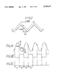
- FIG. 12 there is shown an arrangement of this sort of magnetic or magnetism detecting apparatus.
- a bias magnet 43 produces a bias magnetic field toward a gear 40 functioning as an object under detection
- a sensor unit 42 equipped with an MRE (magnetoresistance element) outputs a signal (i.e., signal indicated in FIG. 13A) in response to a resistance variation of the MRE caused by the rotation of this gear 40 or magnetism.
- a large number of rectangular teeth 41 is formed in the gear 40, and a ratio of a pitch between the successive teeth to a tooth width is selected to be 1:1.
- a signal waveform from the sensor unit 42 is converted into a binary signal (signal shown in FIG. 13B) based on a predetermined threshold value VTH in a comparator 44. Thereafter, a pulse signal shown in FIG. 13C is produced by a monostable circuit (monostable multivibrator) 45, which corresponds to a falling edge of the binary signal.
- the pulse intervals T1', T2' and T3' become equal to each other under the constant rotation as shown in FIGS. 13A to 23C. As a result, such a pulse signal having a constant interval can be obtained.
- the magnetism detecting apparatus when used in, for example, a high-pressure fuel injection pump, a strong demand is made to produce the rotation detecting signals in multi-pulse signal form.
- a signal processing method has been proposed that the detection signal from the MRE is digitized based on the two threshold values VTH1' and VTH2' having the high and low levels, and the pulse signals are produced at both edges of the binary signals, as shown in FIGS. 14A to 14C.
- the threshold values VTH1' and VTH2' which are shifted from the peak value and the bottom value of the MRE detection signal at a preselected ratio are set in order that the signal edge having the constant interval can be obtained under the constant rotation.
- a total number of the resultant pulse signals becomes two times larger than the of the pulse signals illustrated in FIGS. 13A to 13C.
- the present invention has been made to solve the above-described problems, and has an object to provide a magnetism detecting apparatus capable of eliminating distortion contained in a signal waveform of a magnetoresistance effective element (MRE), which is caused when an object under detection having teeth of a gear passes through, even when intervals between gear teeth and a sensor unit are fluctuated, and further capable of reducing fluctuations contained in intervals of a pulse signal obtained by way of a wave shaping operation even when a total number of rotation detecting signals are increased.
- MRE magnetoresistance effective element
- a magnetoresistance element causes a resistance value thereof to be changed in response to a state variation of a biasing magnetic field.
- a waveform shaping means digitizes an output waveform of the magnetoresistance element based on two sets of high and low threshold levels, and produces a pulse signal in response to a rising edge of the digitized output signal and a falling edge thereof. At this time, even when an interval between this magnetoresistance element and the teeth of the object under detection is fluctuated, the output waveforms having the symmetrical shapes can be maintained. As a result, fluctuation in the signal intervals of the pulse signal obtained by the waveform shaping operation can be reduced, and thus the pulse signal having the intervals proportional to the movement speed of the object under detection can be obtained in higher precision.
- the shape of the tooth formed in the object under detection is made of an isosceles triangle, so that the waveform having low distortion can be readily formed even when the intervals between the magnetoresistance element and the teeth of the object under detection change.
- the secondary higher harmonic components can be further reduced, and higher rigidity of the tooth tip portion can be maintained, so that the sintering manufacturing process can be easily performed.
- the teeth of the object under detection is manufactured in such a manner that the averaged tooth width is nearly equal to 1/6 of the pitch between the adjacent teeth, the magnetic vector characteristic shifts caused when the teeth pass through the sensor unit do not easily occur. Also the distorted waveforms constructed of higher harmonic components are not readily produced. As a consequence, the intervals of the pulse signal obtained by way of the waveform shaping operation can be reduced. There are other advantages in manufacturing of the teeth with higher rigidity.
- FIG. 1 is a schematic structural diagram for showing a magnetic rotation detecting apparatus according to an embodiment of the present invention
- FIG. 2 is a sectional view for showing a tooth shape of a gear
- FIGS. 3A to 3C are timing charts for showing a signal process, in which FIG. 3A shows an MRE detection output, FIG. 3B shows an output from a comparator, and FIG. 3C shows an output from a monostable circuit;
- FIG. 4 is a plan view for showing a direction of MRE
- FIG. 5 is a plan view for showing a direction of a magnetic vector applied to MRE
- FIGS. 6A1 to 6B3 are timing charts for explaining a change in magnetic vectors, caused by rotating a gear, in which FIGS. 6A1 to 6A3 are timing charts for showing the magnetic vector variations caused by the gear according to this embodiment, and FIGS. 6B1 to 6B3 are timing charts for showing the magnetic vector variations caused by the prior art gear;
- FIGS. 7A and 7B are diagrams for showing a relationship between a gear tooth shape and a secondary higher harmonic component, in which FIG. 7A is a sectional view of the gear teeth, and FIG. 7B is a diagram for showing the relationship;
- FIGS. 8A and 8B are diagrams for showing a relationship between the gear tooth shape and a sensor output ratio, in which FIG. 8A is a sectional view of the gear teeth, and FIG. 8B is a diagram for showing the relationship;
- FIG. 9A is a diagram for showing a relationship between the gear tooth shape and an amount of waveform distortion (secondary higher harmonic component), FIG. 9B and FIG. 9C(a) to FIG. 9C(e) show such relationships that average tooth widths are changed and a space factor is changed with respect to pitches between the adjacent teeth;
- FIG. 10 is a circuit diagram for showing a threshold value setting circuit according to another embodiment of the present invention.
- FIG. 11 is a circuit diagram for showing another threshold value setting circuit according to a further embodiment of the present invention.
- FIG. 12 is a schematic structural diagram for showing a conventional magnetic detecting apparatus
- FIGS. 13A to 13C are timing charts for showing the conventional signal processing operation, in which FIG. 13A shows an MRE detection output, FIG. 13B shows an output from a comparator, and FIG. 13C shows an output from a monostable circuit;
- FIGS. 14A to 14C are timing charts for showing conventional signal processing operation, in which FIG. 14A shows the MRE detection output, FIG. 14B shows the output from the comparator, and FIG. 14C shows the output from the monostable circuit;
- FIGS. 15A to 15E are timing charts for explaining changes in pulse intervals when a gap is changed in the prior art
- FIGS. 16A to 16E are timing charts for explaining changes in pulse intervals when a gap is changed in the embodiment of the present invention.
- FIGS. 17A to 17E are timing charts for explaining changes in pulse intervals when a gap is changed in the another embodiment of the present invention.
- FIG. 18 is a graph for showing fluctuations in angular accuracy with respect to gaps.
- the magnetic rotation detecting apparatus produces a signal corresponding to, for instance, rotation of a crank angle of an internal combustion engine.
- the magnetic rotation detecting apparatus is arranged by a sensor unit for sensing a rotation of an object to be detected (gear) caused by driving the internal combustion engine by a magnetoresistance element (MRE), and a signal processing unit for shaping a waveform of a sensor output from the sensor unit.
- MRE magnetoresistance element
- FIG. 1 schematically shows an arrangement of the magnetic rotation detecting apparatus.
- a bias magnet 3 constructed of a permanent magnet is magnetized as an N pole, and the other surface thereof is magnetized as an S pole.
- the bias magnet 3 produces the bias magnetic field along a direction substantially normal to the magnetized surface 3a.
- MREs (magnetoresistance elements) 1 and 2 are vapor-deposited on a board or substrate (not shown). One pair of these MREs 1 and 2 are arranged within such a plane involving the bias magnetic field direction produced by the bias magnet 3 and a direction along which teeth is continued in such a manner that these MREs are located at angles of +45 degrees and -45 degrees with respect to this magnetic field direction.
- a constant voltage Vcc is applied between both ends of the MREs 1 and 2.
- a voltage appearing at a midpoint of these MREs 1 and 2 is derived as a sensor output (referred to as an "MRE output" hereinafter).
- MRE output a sensor output
- the bias magnet 3 is made hollow and the board passes through this bias magnet 3 in this case, the bias magnet may be made not hollow but may be arranged on either a front surface of the board, or a rear surface thereof.
- a gear 4 corresponding to the object to be detected is made from a magnetic material.
- a large number of teeth 5 whose cross-sectional shape is a line symmetrical shape, as viewed along an axial direction of the gear 4, is continuously formed on the gear 4.
- Teeth notch portions or notches are formed among a plurality of teeth 5.
- the above-described MREs 1 and 2 are arranged in a preselected interval in such a manner that these MREs are located opposite to the teeth 5.
- the teeth 5 are formed as an isosceles triangular having two sides extending at equal angles.
- a pitch between the adjacent teeth is selected to be 4.6 mm
- a height of a tooth is selected to be 2.3 mm
- angles defined by the respective sides with respect to the gear rotation direction become 45 degrees
- a vertex of angle is selected to be 90 degrees.
- the detection signal outputted from the MREs 1 and 2 (namely, MRE output signal) is supplied via an amplifier 6 to an invert input terminal of a comparator 7, and then is digitized based on predetermined threshold values VTH1 and VTH2 set by a threshold value setting circuit 9 to produce binary signals.
- a threshold value setting circuit 9 both of a peak value (maximum value) and a bottom value (minimum value) of the MRE output signal are used as a first threshold value VTH1 and a second threshold value VTH2 by shifting these peak and bottom values by a preselected ratio in accordance with a voltage difference between both peak/bottom values.
- a signal edge proportional to the movement velocity of the gear 4 is obtained by digitizing the MRE output signal in the comparator 7.
- An output from the comparator 7 is inputted to a one-shot circuit (monostable multivibrator) 8, so that short pulse signals are produced which correspond to the rising edge of the binary signal and the falling edge thereof outputted from the comparator 7.
- the MRE output signal which has passed through the amplifier 6 is entered into a peak hold circuit 10 and a bottom hold circuit 11 within the threshold value setting circuit 9.
- Resistors 12 to 15 are connected in series with each other, and output voltages from a peak hold circuit 10 and the bottom hold circuit 11 are applied to both ends of the series circuit of the resistors 12 to 15.
- the resistor 12 and the resistor 15 have the same resistance value, and the resistor 13 and the resistor 14 have the same resistance value.
- Digital switches 16 and 17 are connected between the both ends of the resistor 13, and also between the both ends of the resistor 14, respectively. These digital switches 16 and 17 are conducted, or interrupted alternately in response to the output signal levels of the comparator 7.
- a midpoint between the resistor 13 and the resistor 14 is connected to a non-invert input terminal of the comparator 7.
- the output terminal of the comparator 7 is connected via an inverter 18 to the digital switch 16, and is directly connected to the digital switch 17.
- the digital switch 16 or the digital switch 17 is turned ON in response to the output from the comparator 7.
- the first threshold value VTH1 is obtained which is lower than the peak value VP by a constant ratio of a variation value "A(VP-VB)”
- the second threshold value VTH2 is obtained which is higher than the bottom value VB by this constant ratio of the variation value "A(VP-VB)”
- the coefficient "A” being defined as 0 ⁇ A ⁇ 1.
- VTH1 VP-A(VP-VB)
- VTH2 VB+A(VP-VB).
- This variation value "A(VP-VB)" is determined based on a difference between the peak value VP and the bottom value VB of the MRE output signal.
- the magnetic rotation detecting apparatus in the above-described circuit arrangement, when the gear 4 is rotated, the magnetic vector B is drawn to the teeth 5 of the gear 4 thereby to be vibrated in connection with this rotation.
- the MREs 1 and 2 produce resistance changes in response to a change in the directions of the magnetic vector B, so that a pair of MREs 1 and 2 exert the magnetic forces in reverse phases with each other.
- the MRE output signal represents a substantially sinusoidal wave as indicated in FIG. 3A.
- the MREs 1 and 2 are arranged at angles of +45 degrees and -45 degrees with respect to the bias magnetic field direction, this MRE output signal has more essentially sinusoidal wave.
- this MRE output signal is compared with the two threshold values VTH1 and VTH2 set by the threshold value setting circuit 9, so that a binary signal as shown in FIG. 3B is outputted from the comparator 7. Furthermore, in the monostable (one shot) circuit 8, a pulse signal is produced and outputted which corresponds to the rising edge of the binary signal and the falling edge thereof derived from the comparator 7, as shown in FIG. 3C.
- the crank angle or rotation angle of the internal combustion engine may be determined based on the interval of this pulse signal, so that engine revolution information can be obtained.
- the MRE output signal is changed in proportion to a vibration angle " ⁇ " of the magnetic vector B.
- ⁇ a vibration angle of the magnetic vector B.
- the MRE output signal is given as follows:
- the MRE output signal depends upon the characteristic of the deflection (vibration) angle ⁇ .
- ⁇ the deflection angle
- FIG. 6A1 to FIG. 6B3 show relationships between deflections of the magnetic vector B with respect to the tooth shapes of the gear 4 and the signal waveforms corresponding thereto.
- FIG. 6A1 shows a tooth shape (triangular teeth) according to this embodiment
- FIG. 6B1 shows the conventional tooth shape (rectangular teeth).
- positions P1, P3 and P5 show such positions that the deflection angle ⁇ of the magnetic vector becomes "0”
- positions P2 and P4 indicate such positions that the deflection angle ⁇ becomes maximum in any of the plus and minus directions.
- the positions P1 to P5 are located in substantially equal intervals.
- the peak position of the MRE output signal corresponding to the position P2 and the bottom position of the MRE output signal corresponding to the position P4 are not deflected to any of the positions P1, P3 and P5, the sine wave of FIG. 6A3 containing less distortion can be obtained.
- the position P2 of peak output level is deflected to the P1-position side, and the position P4 of the bottom output level is deflected to the P5-position side.
- both of the peak position of the MRE output signal and the bottom position thereof are deflected, so that the output signal containing distortion is produced.
- the sinusoidal wave can be obtained as the MRE output signal with respect to the magnetic vector characteristic shown in FIG. 6A1 to FIG. 6A3, whereas the distorted signal wave is obtained in the conventional magnetic vector characteristic shown in FIG. 6B1 to FIG. 6B3.
- the MRE output signal corresponds to a synthesized wave produced from a basic wave and a higher harmonic wave, so that the greater the higher harmonic wave becomes, the higher the distortion degree becomes.
- the tooth shape of the gear is made triangular, it could be confirmed that the secondary higher harmonic component can be considerably reduced.
- FIGS. 7A and 7B show how a relationship between the tooth shape of the gear and the secondary higher harmonic (second harmonics) component
- FIGS. 8A and 8B show a relationship between the tooth shape of the gear and the sensor output ratio.
- FIG. 9A is an experimental graph showing a relationship between the gear tooth shape and the waveform distortion rate (secondary higher harmonic component) in conjunction with the space factor of the tip portion of the gear tooth to the tooth.
- the space factor "SA/(SA+SB)(%)" of the tooth indicated in the abscissa of FIG. 9A denotes such a ratio of SA to (SA+SB), assuming that, as shown in FIG. 9B, a cross-sectional area of a tip portion of tooth occupied from a tip thereto to 10% portion in height is defined as "SA” (namely, cross-sectional area means an area, as viewed from an axial direction, by setting an axis perpendicular to the bias magnetic field direction by the gear moving direction), and another cross-sectional area of a portion within a tooth notch portion, corresponding to the tip portion, is defined by SB.
- the waveform distortion amount (%) of the ordinate in FIG. 9A indicates the magnitude of the secondary higher harmonic component. It should be noted that values of Lp/2, Lp/3, Lp/6 in (a) to (e) of FIG. 9A indicate averaged tooth widths of these teeth, and the averaged tooth width means an average value between the tooth width W1 of the tip portion and the tooth width W2 of the root portion.
- FIG. 9C(a) to FIG. 9C(e) there are represented detailed dimensions of the respective teeth in the examples (a) to (e) in FIG. 9A.
- Symbol “W1” indicates a tooth width of a tip portion
- symbol “W2” represents a tooth width of a root portion.
- the tooth shapes shown in the examples (a) to (c) may cause the MRE output signals to be distorted, because the secondary higher harmonic component is increased.
- the tooth shapes shown in the examples (d) and (e) can apparently suppress the distortion produced in the MRE output signal, because the secondary higher harmonic component is reduced.
- the example (e) is the same as the above-described triangular teeth. Further, it could be recognized that when the tooth width is made narrower than that of the example (d), the secondary higher harmonic component can be further reduced.
- the waveform distortion amount or rate is smaller than, or equal to 2%, but it is convenient to be practically used as the magnetic rotation detecting apparatus. This is because when the waveform distortion amount, namely the secondary higher harmonic component, is large, if the MREs are actually mounted opposite to the gear teeth, then the intervals between the MREs and the gear teeth are fluctuated. As a result, the waveform of the MRE output signal is distorted, and thus the intervals of the pulse signal are shifted. Accordingly, the rotations of the gear teeth cannot be detected in higher accuracy.
- the tooth shape may be made as the rectangular tooth and the triangular tooth, as shown in (d) and (e). It may be an ellipyical tooth shape. Also, another tooth shape only whose tip portion is made sharp may be employed, and a further tooth shape whose central portion has a concave may be employed.
- FIGS. 15A to 15E correspond to the tooth shape of example (a)
- FIGS. 16A to 16E correspond to the tooth shape of example (e)
- FIGS. 17A to 17E correspond to the tooth shape of example (d).
- FIG. 18 is an experimental graphic representation for showing fluctuations or variations in accuracy of rotation angle detection with respect to fluctuations in gaps while the respective tooth shapes of examples (a) to (e) are used as parameters.
- a fuel injection amount may be controlled with higher precision by applying this structure to a rotation angle detecting apparatus of either a diesel engine, or a direct injection type internal combustion engine.
- the present invention may be embodied by employing the following alternative modes other than those of the above-explained embodiment.
- a central voltage is detected from the peak voltage of the peak hold circuit 10 and the bottom voltage of the bottom hold circuit 11 by way of the resistors 30 and 31. Then, this central voltage is applied via an amplifier 32 to a midpoint between the resistors 33 and 34.
- a constant current circuit 35 is connected between one resistor 33 and the digital switch 16, whereas another constant current circuit 36 is connected between the other resistor 34 and the digital switch 17.
- An "R (rounded portion)” may be formed in the tip portion of the triangular tooth.
- the "R” having dimensions smaller than 0.4 to 0.6 mm is allowable to be formed.
- the present invention has been embodied in the rotary movement type magnetic detecting apparatus, the present invention may be alternatively embodied in a linear movement type magnetic detecting apparatus.
Landscapes
- Physics & Mathematics (AREA)
- General Physics & Mathematics (AREA)
- Transmission And Conversion Of Sensor Element Output (AREA)
- Indicating Or Recording The Presence, Absence, Or Direction Of Movement (AREA)
Applications Claiming Priority (2)
| Application Number | Priority Date | Filing Date | Title |
|---|---|---|---|
| JP21892994A JP3368681B2 (ja) | 1994-09-13 | 1994-09-13 | 磁気検出装置 |
| JP6-218929 | 1994-09-13 |
Publications (1)
| Publication Number | Publication Date |
|---|---|
| US5729127A true US5729127A (en) | 1998-03-17 |
Family
ID=16727538
Family Applications (1)
| Application Number | Title | Priority Date | Filing Date |
|---|---|---|---|
| US08/527,200 Expired - Lifetime US5729127A (en) | 1994-09-13 | 1995-09-12 | Magnetism detecting apparatus having gear teeth dimensions for minimal pulse signal distortion |
Country Status (3)
| Country | Link |
|---|---|
| US (1) | US5729127A (de) |
| JP (1) | JP3368681B2 (de) |
| DE (1) | DE19533964B4 (de) |
Cited By (26)
| Publication number | Priority date | Publication date | Assignee | Title |
|---|---|---|---|---|
| US5821745A (en) * | 1995-01-12 | 1998-10-13 | Nippondenso Co., Ltd. | Sensor signal processor having accurate digitizing capabilities |
| US5869962A (en) * | 1995-04-11 | 1999-02-09 | Nippondenso Co., Ltd. | Magnetic detection apparatus for detecting movement of an object having a nonuniform system of teeth |
| GB2332060A (en) * | 1997-12-05 | 1999-06-09 | Ford Global Tech Inc | Speed, direction and acceleration sensor for a rotating shaft |
| US5952824A (en) * | 1997-02-25 | 1999-09-14 | Mitsubishi Denki Kabushiki Kaisha | Magnetic detecting apparatus with giant magnetoresistive sensing element and level shifting waveform processing circuit |
| US5977764A (en) * | 1997-12-05 | 1999-11-02 | Ford Global Technologies, Inc. | Method to sense speed, direction and acceleration for a rotating shaft using a rotor with unequal tooth spacing |
| US6046584A (en) * | 1996-09-27 | 2000-04-04 | Hitachi, Ltd | Internal combustion engine rotating position detector using a differential signal from magnetic sensing portions |
| WO2000036365A1 (en) * | 1998-12-17 | 2000-06-22 | Wabash Technologies Inc. | Magnetic sensor providing digital output of a dynamic analog |
| US6232768B1 (en) * | 1996-01-17 | 2001-05-15 | Allegro Microsystems Inc. | Centering a signal within the dynamic range of a peak detecting proximity detector |
| US6242908B1 (en) | 1996-01-17 | 2001-06-05 | Allegro Microsystems, Inc. | Detection of passing magnetic articles while adapting the detection threshold |
| US6297627B1 (en) | 1996-01-17 | 2001-10-02 | Allegro Microsystems, Inc. | Detection of passing magnetic articles with a peak-to-peak percentage threshold detector having a forcing circuit and automatic gain control |
| US6525531B2 (en) | 1996-01-17 | 2003-02-25 | Allegro, Microsystems, Inc. | Detection of passing magnetic articles while adapting the detection threshold |
| EP1324050A2 (de) * | 2001-12-08 | 2003-07-02 | Philips Intellectual Property & Standards GmbH | Anordnung zum Detektieren der Bewegung eines Encoders |
| WO2003067269A2 (en) * | 2002-02-05 | 2003-08-14 | Allegro Microsystems, Inc. | Peak-to-peak signal detector |
| US20050127685A1 (en) * | 2003-12-03 | 2005-06-16 | Honeywell International Inc. | Latch control by gear position sensing |
| US20080012354A1 (en) * | 2006-05-26 | 2008-01-17 | John Phillip Chevalier | Latch control by gear position sensing |
| US20080143326A1 (en) * | 2006-01-17 | 2008-06-19 | Cory Voisine | Methods and apparatus for magnetic article detection |
| US20080304201A1 (en) * | 2007-06-08 | 2008-12-11 | Nidec Corporation | Voltage signal converter circuit and motor |
| US20090309576A1 (en) * | 2008-06-13 | 2009-12-17 | John Ryan Kess | Speed Sensor Pick-Up for Fluid Device |
| US20130057261A1 (en) * | 2011-09-06 | 2013-03-07 | Fanuc Corporation | Rotation detector and method of producing a rotor in the rotation detector |
| US8598867B2 (en) | 2010-06-04 | 2013-12-03 | Allegro Microsystems, Llc | Circuits and methods for generating a threshold signal used in a motion detector |
| US8723512B1 (en) | 2012-11-26 | 2014-05-13 | Allegro Microsystems, Llc | Circuits and methods for generating a threshold signal used in a magnetic field sensor based on a peak signal associated with a prior cycle of a magnetic field signal |
| US9476899B2 (en) | 2013-08-30 | 2016-10-25 | Allegro Microsystems, Llc | Circuits and methods for generating a threshold signal used in a motion detector in accordance with a least common multiple of a set of possible quantities of features upon a target |
| US9520871B2 (en) | 2012-01-05 | 2016-12-13 | Allegro Microsystems, Llc | Methods and apparatus for supply voltage transient protection for maintaining a state of a sensor output signal |
| US9778326B2 (en) | 2014-03-11 | 2017-10-03 | Allegro Microsystems, Llc | Circuits and methods for limiting a smallest separation of thresholds in a magnetic field sensor |
| CN113309618A (zh) * | 2021-06-30 | 2021-08-27 | 中国航发动力股份有限公司 | 一种燃气轮机低压转速信号波动的排故方法 |
| US11119113B2 (en) | 2017-08-14 | 2021-09-14 | Volkswagen Aktiengesellschaft | Rotational speed sensor arrangement |
Families Citing this family (4)
| Publication number | Priority date | Publication date | Assignee | Title |
|---|---|---|---|---|
| DE19623742A1 (de) * | 1996-06-14 | 1997-12-18 | Wittenstein Motion Contr Gmbh | Einrichtung zur Verschiebeweg- und/oder Positionserfassung bei einem Spindeltrieb |
| DE19842990A1 (de) * | 1998-09-21 | 2000-04-13 | Bosch Gmbh Robert | Vorrichtung und Verfahren zur Erfassung der Drehbewegung einer Welle |
| JP5285627B2 (ja) * | 2010-01-07 | 2013-09-11 | 株式会社豊田中央研究所 | 電圧処理回路 |
| US10801360B2 (en) * | 2018-06-29 | 2020-10-13 | Pratt & Whitney Canada Corp. | Phonic wheel with output voltage tuning |
Citations (8)
| Publication number | Priority date | Publication date | Assignee | Title |
|---|---|---|---|---|
| US3366874A (en) * | 1962-11-16 | 1968-01-30 | Hasler Ag | Device responsive to magnetic bodies and magnetic fields |
| JPS5531964A (en) * | 1978-08-30 | 1980-03-06 | Nippon Denso Co Ltd | Rotary angle detector |
| JPS63205516A (ja) * | 1987-02-23 | 1988-08-25 | Nippon Denso Co Ltd | 近接センサ |
| JPS6479614A (en) * | 1987-09-22 | 1989-03-24 | Canon Kk | Encoder apparatus |
| US4853632A (en) * | 1981-02-07 | 1989-08-01 | Hitachi, Ltd. | Apparatus for magnetically detecting a position of a movable magnetic body |
| EP0539602A1 (de) * | 1991-05-10 | 1993-05-05 | Fanuc Ltd. | Magnetoresistiver rotationsdetektor |
| US5304926A (en) * | 1992-04-08 | 1994-04-19 | Honeywell Inc. | Geartooth position sensor with two hall effect elements |
| US5359287A (en) * | 1989-01-18 | 1994-10-25 | Nippondenso Co., Ltd. | Magnetic detecting circuit having magnetoresistance effective elements oriented in at least two different directions |
Family Cites Families (3)
| Publication number | Priority date | Publication date | Assignee | Title |
|---|---|---|---|---|
| US3900814A (en) * | 1973-05-31 | 1975-08-19 | Denki Onkyo Company Ltd | Revolution sensing apparatus |
| FR2670888B1 (fr) * | 1990-12-19 | 1994-05-27 | Aerospatiale | Capteur de position angulaire a magnetoresistances. |
| DE4341890C2 (de) * | 1992-12-09 | 2003-11-06 | Denso Corp | Magnetische Detektionseinrichtung |
-
1994
- 1994-09-13 JP JP21892994A patent/JP3368681B2/ja not_active Expired - Lifetime
-
1995
- 1995-09-12 US US08/527,200 patent/US5729127A/en not_active Expired - Lifetime
- 1995-09-13 DE DE19533964A patent/DE19533964B4/de not_active Expired - Lifetime
Patent Citations (8)
| Publication number | Priority date | Publication date | Assignee | Title |
|---|---|---|---|---|
| US3366874A (en) * | 1962-11-16 | 1968-01-30 | Hasler Ag | Device responsive to magnetic bodies and magnetic fields |
| JPS5531964A (en) * | 1978-08-30 | 1980-03-06 | Nippon Denso Co Ltd | Rotary angle detector |
| US4853632A (en) * | 1981-02-07 | 1989-08-01 | Hitachi, Ltd. | Apparatus for magnetically detecting a position of a movable magnetic body |
| JPS63205516A (ja) * | 1987-02-23 | 1988-08-25 | Nippon Denso Co Ltd | 近接センサ |
| JPS6479614A (en) * | 1987-09-22 | 1989-03-24 | Canon Kk | Encoder apparatus |
| US5359287A (en) * | 1989-01-18 | 1994-10-25 | Nippondenso Co., Ltd. | Magnetic detecting circuit having magnetoresistance effective elements oriented in at least two different directions |
| EP0539602A1 (de) * | 1991-05-10 | 1993-05-05 | Fanuc Ltd. | Magnetoresistiver rotationsdetektor |
| US5304926A (en) * | 1992-04-08 | 1994-04-19 | Honeywell Inc. | Geartooth position sensor with two hall effect elements |
Cited By (37)
| Publication number | Priority date | Publication date | Assignee | Title |
|---|---|---|---|---|
| US5821745A (en) * | 1995-01-12 | 1998-10-13 | Nippondenso Co., Ltd. | Sensor signal processor having accurate digitizing capabilities |
| US5869962A (en) * | 1995-04-11 | 1999-02-09 | Nippondenso Co., Ltd. | Magnetic detection apparatus for detecting movement of an object having a nonuniform system of teeth |
| US6525531B2 (en) | 1996-01-17 | 2003-02-25 | Allegro, Microsystems, Inc. | Detection of passing magnetic articles while adapting the detection threshold |
| US6232768B1 (en) * | 1996-01-17 | 2001-05-15 | Allegro Microsystems Inc. | Centering a signal within the dynamic range of a peak detecting proximity detector |
| US6242908B1 (en) | 1996-01-17 | 2001-06-05 | Allegro Microsystems, Inc. | Detection of passing magnetic articles while adapting the detection threshold |
| US6297627B1 (en) | 1996-01-17 | 2001-10-02 | Allegro Microsystems, Inc. | Detection of passing magnetic articles with a peak-to-peak percentage threshold detector having a forcing circuit and automatic gain control |
| US6046584A (en) * | 1996-09-27 | 2000-04-04 | Hitachi, Ltd | Internal combustion engine rotating position detector using a differential signal from magnetic sensing portions |
| US5952824A (en) * | 1997-02-25 | 1999-09-14 | Mitsubishi Denki Kabushiki Kaisha | Magnetic detecting apparatus with giant magnetoresistive sensing element and level shifting waveform processing circuit |
| GB2332060B (en) * | 1997-12-05 | 2002-02-20 | Ford Global Tech Inc | Speed, direction and acceleration sensor for a rotating shaft |
| US5977764A (en) * | 1997-12-05 | 1999-11-02 | Ford Global Technologies, Inc. | Method to sense speed, direction and acceleration for a rotating shaft using a rotor with unequal tooth spacing |
| GB2332060A (en) * | 1997-12-05 | 1999-06-09 | Ford Global Tech Inc | Speed, direction and acceleration sensor for a rotating shaft |
| US6211670B1 (en) * | 1998-12-17 | 2001-04-03 | Optek Technology, Inc. | Magnetic sensing device for outputting a digital signal as a dynamic representation of an analog signal |
| WO2000036365A1 (en) * | 1998-12-17 | 2000-06-22 | Wabash Technologies Inc. | Magnetic sensor providing digital output of a dynamic analog |
| EP1324050A2 (de) * | 2001-12-08 | 2003-07-02 | Philips Intellectual Property & Standards GmbH | Anordnung zum Detektieren der Bewegung eines Encoders |
| EP1324050A3 (de) * | 2001-12-08 | 2004-05-19 | Philips Intellectual Property & Standards GmbH | Anordnung zum Detektieren der Bewegung eines Encoders |
| US6919720B2 (en) | 2002-02-05 | 2005-07-19 | Allegro Microsystems, Inc. | Peak-to-peak signal detector |
| WO2003067269A2 (en) * | 2002-02-05 | 2003-08-14 | Allegro Microsystems, Inc. | Peak-to-peak signal detector |
| US20030160696A1 (en) * | 2002-02-05 | 2003-08-28 | Ravi Vig | Peak-to-peak signal detector |
| WO2003067269A3 (en) * | 2002-02-05 | 2004-03-25 | Allegro Microsystems Inc | Peak-to-peak signal detector |
| US20050127685A1 (en) * | 2003-12-03 | 2005-06-16 | Honeywell International Inc. | Latch control by gear position sensing |
| US20080143326A1 (en) * | 2006-01-17 | 2008-06-19 | Cory Voisine | Methods and apparatus for magnetic article detection |
| US7548056B2 (en) | 2006-01-17 | 2009-06-16 | Allegro Microsystems, Inc. | Methods and apparatus for magnetic article detection |
| US20080012354A1 (en) * | 2006-05-26 | 2008-01-17 | John Phillip Chevalier | Latch control by gear position sensing |
| US20080304201A1 (en) * | 2007-06-08 | 2008-12-11 | Nidec Corporation | Voltage signal converter circuit and motor |
| US8742750B2 (en) * | 2008-06-13 | 2014-06-03 | Eaton Corporation | Speed sensor pick-up for fluid device |
| US20090309576A1 (en) * | 2008-06-13 | 2009-12-17 | John Ryan Kess | Speed Sensor Pick-Up for Fluid Device |
| US8598867B2 (en) | 2010-06-04 | 2013-12-03 | Allegro Microsystems, Llc | Circuits and methods for generating a threshold signal used in a motion detector |
| US9140536B2 (en) | 2010-06-04 | 2015-09-22 | Allegro Microsystems, Llc | Circuits and methods using a first cycle of a signal to generate a threshold signal used for comparing to a second later cycle of the signal |
| US20130057261A1 (en) * | 2011-09-06 | 2013-03-07 | Fanuc Corporation | Rotation detector and method of producing a rotor in the rotation detector |
| US9360494B2 (en) * | 2011-09-06 | 2016-06-07 | Fanuc Corporation | Rotation detector and method of producing a rotor in the rotation detector |
| US9520871B2 (en) | 2012-01-05 | 2016-12-13 | Allegro Microsystems, Llc | Methods and apparatus for supply voltage transient protection for maintaining a state of a sensor output signal |
| US8723512B1 (en) | 2012-11-26 | 2014-05-13 | Allegro Microsystems, Llc | Circuits and methods for generating a threshold signal used in a magnetic field sensor based on a peak signal associated with a prior cycle of a magnetic field signal |
| US9476899B2 (en) | 2013-08-30 | 2016-10-25 | Allegro Microsystems, Llc | Circuits and methods for generating a threshold signal used in a motion detector in accordance with a least common multiple of a set of possible quantities of features upon a target |
| US9778326B2 (en) | 2014-03-11 | 2017-10-03 | Allegro Microsystems, Llc | Circuits and methods for limiting a smallest separation of thresholds in a magnetic field sensor |
| US11119113B2 (en) | 2017-08-14 | 2021-09-14 | Volkswagen Aktiengesellschaft | Rotational speed sensor arrangement |
| CN113309618A (zh) * | 2021-06-30 | 2021-08-27 | 中国航发动力股份有限公司 | 一种燃气轮机低压转速信号波动的排故方法 |
| CN113309618B (zh) * | 2021-06-30 | 2022-08-02 | 中国航发动力股份有限公司 | 一种燃气轮机低压转速信号波动的排故方法 |
Also Published As
| Publication number | Publication date |
|---|---|
| JP3368681B2 (ja) | 2003-01-20 |
| DE19533964B4 (de) | 2010-07-08 |
| JPH0882634A (ja) | 1996-03-26 |
| DE19533964A1 (de) | 1996-03-14 |
Similar Documents
| Publication | Publication Date | Title |
|---|---|---|
| US5729127A (en) | Magnetism detecting apparatus having gear teeth dimensions for minimal pulse signal distortion | |
| US5869962A (en) | Magnetic detection apparatus for detecting movement of an object having a nonuniform system of teeth | |
| US5574364A (en) | Position detector including a reference position wherein the sensor is saturating the MR sensor for preventing hysteresis and in a bridge circuit | |
| US5841276A (en) | Magnetic gear rotation sensor | |
| US5019776A (en) | Magnetic position detection apparatus having two magnetic recording medium tracks with magnetoresistors arranged in a bridge circuit so as to eliminate even order harmonic distortion | |
| US5304926A (en) | Geartooth position sensor with two hall effect elements | |
| US5656936A (en) | Displacement detecting device | |
| US5644226A (en) | Magnetic detector having a bias magnet and magnetoresistive elements shifted away from the center of the magnet | |
| JP2572026B2 (ja) | 速度信号発生装置 | |
| JPS63225124A (ja) | 磁気的位置検出装置 | |
| US6046584A (en) | Internal combustion engine rotating position detector using a differential signal from magnetic sensing portions | |
| US20020140420A1 (en) | Motion detecting device using magnetoresistive unit | |
| US5198762A (en) | Magnetic sensor having spaced magneto-resistance elements | |
| JP3311429B2 (ja) | 基準位置検出装置 | |
| US5153513A (en) | Apparatus for processing output signal of sensor with magnetic rotary member | |
| JPH1019602A (ja) | 磁気エンコーダ | |
| JPH1019601A (ja) | 磁気検出装置 | |
| JP2722605B2 (ja) | 磁気エンコーダ | |
| USRE34443E (en) | Apparatus magnetically detecting position or speed of moving body utilizing bridge circuit with series connected MR elements | |
| JP2550049B2 (ja) | 磁気的に位置や速度を検出する装置 | |
| JPS6266116A (ja) | 回転センサ | |
| JPH0474929A (ja) | 移動量検出センサーとそれを用いた自動車 | |
| JPH10311742A (ja) | 位置検出センサ | |
| JPH10153454A (ja) | 磁気検出装置及び磁気抵抗効果素子 | |
| JP2598782B2 (ja) | 磁気エンコーダ装置 |
Legal Events
| Date | Code | Title | Description |
|---|---|---|---|
| AS | Assignment |
Owner name: NIPPONDENSO CO., LTD., JAPAN Free format text: ASSIGNMENT OF ASSIGNORS INTEREST;ASSIGNORS:TAMURA, TATSUO;YAGI, KENJI;MAKINO, YASUAKI;AND OTHERS;REEL/FRAME:007669/0640;SIGNING DATES FROM 19950822 TO 19950823 |
|
| STCF | Information on status: patent grant |
Free format text: PATENTED CASE |
|
| FPAY | Fee payment |
Year of fee payment: 4 |
|
| FPAY | Fee payment |
Year of fee payment: 8 |
|
| FPAY | Fee payment |
Year of fee payment: 12 |