US5678134A - Cleaning device for an image forming apparatus - Google Patents
Cleaning device for an image forming apparatus Download PDFInfo
- Publication number
- US5678134A US5678134A US08/624,004 US62400496A US5678134A US 5678134 A US5678134 A US 5678134A US 62400496 A US62400496 A US 62400496A US 5678134 A US5678134 A US 5678134A
- Authority
- US
- United States
- Prior art keywords
- cleaning
- endless
- roller
- toner
- temperature
- Prior art date
- Legal status (The legal status is an assumption and is not a legal conclusion. Google has not performed a legal analysis and makes no representation as to the accuracy of the status listed.)
- Expired - Fee Related
Links
Images


Classifications
-
- G—PHYSICS
- G03—PHOTOGRAPHY; CINEMATOGRAPHY; ANALOGOUS TECHNIQUES USING WAVES OTHER THAN OPTICAL WAVES; ELECTROGRAPHY; HOLOGRAPHY
- G03G—ELECTROGRAPHY; ELECTROPHOTOGRAPHY; MAGNETOGRAPHY
- G03G15/00—Apparatus for electrographic processes using a charge pattern
- G03G15/14—Apparatus for electrographic processes using a charge pattern for transferring a pattern to a second base
- G03G15/16—Apparatus for electrographic processes using a charge pattern for transferring a pattern to a second base of a toner pattern, e.g. a powder pattern, e.g. magnetic transfer
- G03G15/1605—Apparatus for electrographic processes using a charge pattern for transferring a pattern to a second base of a toner pattern, e.g. a powder pattern, e.g. magnetic transfer using at least one intermediate support
- G03G15/161—Apparatus for electrographic processes using a charge pattern for transferring a pattern to a second base of a toner pattern, e.g. a powder pattern, e.g. magnetic transfer using at least one intermediate support with means for handling the intermediate support, e.g. heating, cleaning, coating with a transfer agent
-
- G—PHYSICS
- G03—PHOTOGRAPHY; CINEMATOGRAPHY; ANALOGOUS TECHNIQUES USING WAVES OTHER THAN OPTICAL WAVES; ELECTROGRAPHY; HOLOGRAPHY
- G03G—ELECTROGRAPHY; ELECTROPHOTOGRAPHY; MAGNETOGRAPHY
- G03G15/00—Apparatus for electrographic processes using a charge pattern
- G03G15/20—Apparatus for electrographic processes using a charge pattern for fixing, e.g. by using heat
- G03G15/2003—Apparatus for electrographic processes using a charge pattern for fixing, e.g. by using heat using heat
- G03G15/2014—Apparatus for electrographic processes using a charge pattern for fixing, e.g. by using heat using heat using contact heat
- G03G15/2017—Structural details of the fixing unit in general, e.g. cooling means, heat shielding means
- G03G15/2025—Structural details of the fixing unit in general, e.g. cooling means, heat shielding means with special means for lubricating and/or cleaning the fixing unit, e.g. applying offset preventing fluid
-
- G—PHYSICS
- G03—PHOTOGRAPHY; CINEMATOGRAPHY; ANALOGOUS TECHNIQUES USING WAVES OTHER THAN OPTICAL WAVES; ELECTROGRAPHY; HOLOGRAPHY
- G03G—ELECTROGRAPHY; ELECTROPHOTOGRAPHY; MAGNETOGRAPHY
- G03G2215/00—Apparatus for electrophotographic processes
- G03G2215/16—Transferring device, details
- G03G2215/1647—Cleaning of transfer member
- G03G2215/1661—Cleaning of transfer member of transfer belt
-
- G—PHYSICS
- G03—PHOTOGRAPHY; CINEMATOGRAPHY; ANALOGOUS TECHNIQUES USING WAVES OTHER THAN OPTICAL WAVES; ELECTROGRAPHY; HOLOGRAPHY
- G03G—ELECTROGRAPHY; ELECTROPHOTOGRAPHY; MAGNETOGRAPHY
- G03G2215/00—Apparatus for electrophotographic processes
- G03G2215/16—Transferring device, details
- G03G2215/1676—Simultaneous toner image transfer and fixing
- G03G2215/1695—Simultaneous toner image transfer and fixing at the second or higher order transfer point
Definitions
- the present invention relates generally to a cleaning device for an image forming apparatus, and more particularly to a cleaning device for removing toner left on the surface of an endless member, such as a transfer belt, a dielectric belt or a heat roller, which is put in contact with a recording medium at the time of fixation.
- Jpn. Pat. Appln. KOKOKU Publication No. 4-45829 discloses an image forming apparatus wherein a toner image is formed on an image carrying body and the formed toner image is transferred onto a recording paper sheet.
- a toner image is formed on a photosensitive drum 201, and the formed toner image is transferred onto an intermediate transfer roller 205.
- a recording sheet 213 is pressed on the intermediate transfer roller 205 by means of a fixing pressing roller 207.
- the toner image is transferred onto the recording sheet 213.
- the image forming apparatus includes a cleaning roller 206 for cleaning toner left on the intermediate transfer roller 205 after the transfer.
- the cleaning roller 206 as shown in FIG. 27B, comprises a roller core 206a formed of a metal such as aluminum, a heat-resistant rubber layer 206b surrounding the roller core 206a, and a nickel thin layer 206c which can be easily heated and is provided around the rubber layer 206b.
- the nickel thin layer 206c of the cleaning roller 206 can be put in close contact with an outermost silicone-rubber layer 205a of the intermediate transfer roller 205. Since the specific heat of the nickel thin layer 206c is low, the temperature of the nickel thin layer 206c can be easily raised up to the temperature of the intermediate transfer roller 205.
- the nickel thin layer 206c absorbs a little amount of heat from the intermediate transfer roller 205.
- Toner which has not been transferred onto the recording sheet 213 and has been left on the intermediate transfer roller 205, is heated up to the temperature of the intermediate transfer roller 205 put in close contact with the surface of the cleaning roller 206.
- the molten toner is adhered to the nickel thin layer 206c of the cleaning roller 206 with high adhesive force.
- the intermediate transfer roller 205 is cleaned.
- the nickel thin film 206c wears the silicone rubber 205a on the surface of the intermediate transfer roller 205 and greatly shortens the life of the roller 205.
- the temperature of the nickel thin layer 206c of the cleaning roller 206 is made equal to that of the intermediate transfer roller 205 and the cleaning roller 206 cleans the intermediate transfer roller 205 by making use of a difference in adhesive force of molten toner on the nickel thin layer 206c and intermediate transfer roller 205.
- Jpn. Pat. Appln. KOKAI No. 61-55677 discloses a fixing apparatus, as shown in FIG. 28.
- a fixing apparatus 416 comprises a first roller 416a and a second roller 416b.
- a paper sheet 420 on which a toner image 420a is formed is clamped under pressure between the two rollers 416a and 416b, and thus the toner image 420a is fixed.
- a first cleaning roller 417 which is put in contact with the first roller 416a and on which felt is wound, rotates in accordance with rotation of the first roller 416a and cleans the first roller 416a.
- a second cleaning roller 418 which is put in contact with the second roller 416b and on which felt is wound, rotates in accordance with the second roller 416b and cleans the second roller 416b.
- first cleaning roller 417 and second cleaning roller 418 are put in pressure contact with the first roller 416a and second roller 416b, respectively, the friction between the rollers shortens the lives of the first roller 416a and second roller 416b.
- the cleaning rollers 417 and 418 if stained, need to be replaced with new ones, resulting in a high maintenance cost on the side of the user.
- Jpn. Pat. Appln. KOKAI Publication No. 2-309378 discloses an apparatus for thermally cleaning a belt of a belt fixing device, as shown in FIG. 29A.
- a fixing film 305 is passed over a driving roller 301 and a driven roller 302 through the region between a heater 304 and a pressing roller 303.
- the fixing film 305 is driven by the driving roller 301.
- Offset toner 312 adheres to the fixing film 305 which has fixed toner on a recording paper sheet 318.
- the offset toner 312 is melted by the driven roller 302 heated by a halogen lamp 306 and adhered to a cleaning roller 307.
- the fixing film 305 is cleaned.
- FIG. 29B shows a structure wherein a halogen lamp 306A is provided inside the cleaning roller 307, in contrast to the apparatus shown in FIG. 29A wherein the halogen lamp 306 is provided inside the driven roller 302.
- the offset toner 312 adhered to the fixing film 305 is melted by the cleaning roller 307 heated by the halogen lamp 306A.
- the molten toner adheres to the cleaning roller 307 and thus the fixing film 305 is cleaned.
- the cleaning roller 307 is not heated by the heat of the fixing film 305. Instead, the cleaning roller 307 is heated by the halogen lamp 306 or 306A, thereby cleaning the fixing film 305.
- the heating source is provided, this third prior art, like the first prior art, is silent on the control of the temperature of toner to be cleaned.
- Jpn. Pat. Appln. KOKAI Publication No. 1-232377 discloses a cleaning device for an image forming apparatus wherein a toner image formed on a recording member is transferred onto a transfer medium.
- the structure of this apparatus is shown in FIG. 30.
- a cleaning brush 402 for removing toner left on a photosensitive drum 401 is rotatably supported at one end portion of an arm 404.
- the arm 404 is moved in a swinging manner by a motor 405.
- the cleaning brush 402 is put in contact with and separated from the photosensitive drum 401.
- a duct 403 sucks and exhausts toner removed from the surface of the photosensitive drum 401 by the cleaning brush 402.
- the motor 405 is driven by a driver 406.
- the driver 406 is controlled by a printer controller 408.
- the printer controller 408 is controlled by a host 407 and controls a printing mechanism unit 409 such as a printer.
- the cleaning brush 402 is retreated from the surface of the photosensitive drum 401, thereby preventing a filming phenomenon (i.e. a phenomenon in which toner adheres to the surface of a photosensitive drum) from occurring due to long-time contact between the cleaning brush 402 and the surface of the photosensitive drum 401.
- a filming phenomenon i.e. a phenomenon in which toner adheres to the surface of a photosensitive drum
- the cleaning effect increases or decreases, depending on the surface temperatures of the photosensitive drum 401 and cleaning brush 402.
- the fourth prior art is silent on the idea that a high cleaning effect is maintained by controlling the contact/separation of the cleaning brush 402.
- An object of the present invention is to provide a cleaning technique for realizing a cost-effective image forming apparatus for forming a high-quality image on a recording paper sheet.
- FIG. 1 shows an image forming apparatus having a cleaning device according to a first embodiment of the present invention
- FIG. 2 shows an image forming apparatus having a cleaning device according to a second embodiment of the present invention
- FIG. 3 shows a cleaning device according to a third embodiment of the invention
- FIG. 4 shows an image forming apparatus having a cleaning device according to a fourth embodiment of the invention
- FIG. 5 shows a cleaning device according to a fifth embodiment of the invention
- FIG. 6 shows a cleaning device according to a sixth embodiment of the invention
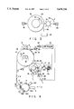
- FIG. 7 shows a cleaning device according to a seventh embodiment of the invention.
- FIG. 8 shows a cleaning device according to an eighth embodiment of the invention.
- FIG. 9 shows a cleaning device according to a ninth embodiment of the invention.
- FIG. 10A shows a cleaning device according to a tenth embodiment of the invention
- FIG. 10B shows another cleaning device according to the tenth embodiment of the invention.
- FIG. 11 shows a cleaning device according to an eleventh embodiment of the invention
- FIG. 12B shows a cross-sectional structure of a cleaning roller of the apparatus shown in FIG. 12A;
- FIG. 12C shows the state in which a cleaning film shown in FIG. 12B is removed
- FIG. 13 shows a transfer device serving also as cleaning device, according to a thirteenth embodiment of the invention.
- FIG. 14 shows a transfer device serving also as cleaning device, according to a fourteenth embodiment of the invention.
- FIG. 17 illustrates, as a seventeenth embodiment of the invention, the principle of cleaning in the preceding embodiments
- FIG. 18 shows a cleaning device according to an eighteenth embodiment of the invention.
- FIG. 19A shows an image forming apparatus according to a nineteenth embodiment of the invention.
- FIG. 19B shows a cleaning device in FIG. 19A
- FIG. 24 is a flow chart illustrating the operation of an image forming apparatus according to a twenty-fourth embodiment of the invention.
- FIGS. 26A and 26B are flow charts illustrating the operation of an image forming apparatus according to a twenty-sixth embodiment of the invention.
- FIG. 27A shows an example of prior art of a cleaning device for an image forming apparatus
- FIG. 27B shows the cleaning device shown in FIG. 27A
- FIG. 29A shows an example of prior art of a cleaning device for a belt fixing device
- FIG. 29B shows another example of prior art of a cleaning device for a belt fixing device, differing in part from the cleaning device shown in FIG. 29A;
- FIG. 30 shows an example of prior art of a cleaning device having a mechanism put in contact with and separated from a recording drum of an image forming apparatus.
- An endless belt 2 is passed, and runs, between a visible image forming unit 3 provided in the lower part of the apparatus and a thermal transfer unit 4 provided in the upper part of the apparatus.
- An electrostatic latent image is formed on the endless belt 2 by an electrostatic image forming device 5, which is, for example, an ion stream control type recording device or a device for forming a latent image by a laser beam, etc., after uniformly charging the endless belt 2.
- toner is adhered to the electrostatic latent image by a developing device 103.
- a toner image 9 is formed and the electrostatic latent image is made visible.
- the endless belt 2 with the toner image 9 runs between a heat roller 8 and a pressing roller 6 along with a recording paper sheet 7 conveyed in a direction P.
- the heat roller 8 is heated by a heat roller heater 81 provided within the heat roller 8 itself.
- the endless belt 2 with the toner image 9 is heated on the reverse side thereof by the heat roller 8, and the toner image 9 on the endless belt 2 is softened.
- the toner image 9 is thermally transferred onto the recording sheet 7 and at the same time the toner image 9 is pressed by the pressing roller 6 and fixed on the recording sheet 7.
- the recording sheet 7 and the endless belt 2 are separated by a separating device (not shown), and the recording sheet 7 is discharged to a discharge tray (not shown), etc.
- the obverse face of the endless belt 2 is generally coated with a material such as fluoroplastics or silicone with high separation properties to toner and high heat resistance.
- the transfer ratio of toner onto the recording sheet is not 100%.
- a small amount of residual molten toner 92 is left on the obverse face of the endless belt 2.
- the residual toner 92 is removed by a cleaning device 1.
- the endless belt 2 without residual toner 92 is passed through a heat exchanger 101 and restored to an electrically neutral state by an eraser 102.
- the endless belt 2 can be used for the formation of the next image.
- the cleaning device 1 has a cleaning roller 10.
- the surface of the cleaning roller 10 is coated with an elastic member 11, thereby preventing wear of the endless belt 2 and cleaning roller 10.
- the elastic member 11 is formed of a heat-resistant resin or rubber which does not damage the endless belt 2 and has a greater surface energy than the surface of the endless belt 2.
- the resin are phenol resin, melamine resin, aryl resin, furan resin, unsaturated polyester resin, alkyd resin, epoxy resin, silicone resin, polyimide, polyamideimide, polyethersulfone, polysulfone, polyarylether, polyarylsulfone, polybutadiene, fluoroplastics, thermoplastic polyester, and polyphenylene sulfide.
- Examples of the rubber are chloroprene acryl rubber, nitrile butadiene rubber, isobutylen isoprene rubber, ethylene propylene rubber, silicone rubber, chlorosulfonated polyethylene rubber, chlorinated polyethylene rubber, acryl rubber, and epichlorohydrin rubber.
- the cleaning roller 10 is put in contact with the endless belt 2 and is rotated in a direction C in accordance with the rotation of the belt 2 in a direction A of movement of the endless belt 2.
- the softened residual toner 92 adheres to the surface of the cleaning roller 10 by the adhesive force acting between the residual toner 92 and the surface of the cleaning roller 10. As a result, the surface of the endless belt 2 is cleaned.
- the elastic member was formed of polyimide, MYLARTM, (polyester film) polyolefin resin, or silicone rubber.
- the cleaning device 1 is provided with a contacting/separating mechanism for contacting/separating the cleaning roller 10 with/from the endless belt 2.
- the contacting/separating mechanism 34 comprises an electromagnetic clutch 13 and a spring 14.
- the cleaning device 1 includes a stain sensor 18 for sensing the stain of the cleaning roller 10 and a controller 51 for controlling the supply of power to the electromagnetic clutch 13.
- the electromagnetic clutch 13 When the electromagnetic clutch 13 is activated, the cleaning roller 10 is brought into contact with the endless belt 2, as indicated by a solid line.
- the supply of power to the electromagnetic clutch 13 is stopped, the cleaning roller 10 is separated from the endless belt 2 by the force of the spring 14, as indicated by a two-dot-and-dash line.
- the stain sensor 18 is, for example, a device for radiating light on the cleaning roller 10 and sensing reflected light. As the surface of the cleaning roller 10 is covered with the adhered toner 93, the amount of reflection light from the cleaning roller 10 decreases and the condition of stain is detected. Alternatively, the stain sensor 18 is a device for sensing a distance between itself and the cleaning roller 10. As the surface of the cleaning roller 10 is covered with the adhered toner 93, the distance between the device and the cleaning roller 10 decreases and the condition of the stain is detected.
- the cleaning device 1 further includes a refresh blade 12 as refresh member for removing the adhered toner 93 from the surface of the cleaning roller 10.
- the adhered toner 93 is basically formed of a thermoplastic resin, the viscosity of the toner 93 decreases as it is cooled, and the cooled toner 93 is easily broken by mechanical shock.
- the refresh blade 12 is put in mechanical contact with the adhered toner 93 on the cleaning roller 10, thereby easily and completely removing the toner 93 from the cleaning roller 10.
- the cleaning roller 10 exhibits the same cleaning performance as a new one. Since the cleaning roller 10, which has conventionally been a consumable part, is easily and completely refreshed and permanently used. Thus, the running cost is reduced and the maintenance cost on the side of the user is reduced.
- the cleaning roller 10 can be contacted/separated with/from the endless belt 2, the cleaning roller 10 can be cooled in a short time, independent of the temperature of the endless belt 2.
- the refresh time is shortened and accordingly the halt time of the image forming apparatus in which the cleaning device 1 is built is shortened.
- the cleaning roller 10 is separated from the endless belt 2 at the time of refreshing, the endless belt 2 need not be driven and the wear of the belt 2 is prevented.
- dispersed toner produced at the refresh time does not readhere to the endless belt 2, and the image quality of the image forming apparatus is stabilized.
- the cleaning roller 10 While the main switch of the image forming apparatus is turned off, the cleaning roller 10 is separated from the endless belt 2.
- the main switch When the main switch is turned on, the refresh operation is performed during a start-up time of the image forming apparatus, following which the cleaning roller 10 is put in contact with the endless belt 2. Since this operational sequence is preset, there is no halt time period on the user side, and the cleaning roller 10 can be refreshed in a predetermined time. Besides, since the cleaning roller 10 is separated from the endless belt 2 at the time of turn-off of the apparatus, wear of the endless belt 2 is prevented.
- the cleaning roller 10 is automatically separated from the endless belt 2.
- the cleaning roller 10 is automatically separated from the endless belt 2.
- the cleaning roller 10 which has conventionally been a consumable part can be easily and completely refreshed and permanently used.
- the running cost is reduced and the maintenance cost on the side of the user is reduced.
- the cleaning roller 10 need not be replaced as a consumable part, high reliability and maintenance-free construction demanded for computer network systems, etc. can be achieved.
- FIG. 2 shows an image forming apparatus having the cleaning device of this embodiment.
- An image forming process is performed in the following manner.
- An electrostatic latent image is formed on a drum 104 by means of an electrostatic image forming device 5, which is, for example, an ion stream control type recording device or a device for forming a latent image by a laser beam, etc. after uniformly charging the drum 104.
- toner is adhered to the electrostatic latent image by a developing device 103.
- a toner image 9 is formed and the electrostatic latent image is made visible.
- the toner image 9 on the drum 104 is transferred onto a recording paper sheet 7 (which is conveyed in a direction P).by a transfer member 105.
- the transfer member 105 is, for example, an electrostatic transfer member or a thermal transfer member.
- the drum 104 is cleaned by a cleaner 106 and restored to an electrically neutral state by an eraser 102 for the formation of the next image.
- the recording sheet 7 bearing the transfer toner image 91 in an unfixed state is transferred to a point S between a heat roller 8 and a pressing roller 6 and heated by the heat roller 8.
- the transfer toner image 91 is softened and thermally fixed on the recording sheet 7.
- the recording sheet 7 is separated by a separating device (not shown).
- a cleaning device 1 for removing the residual toner 92 is provided.
- the cleaning device 1 has a cleaning roller 10 driven by the heat roller 8 in a direction C.
- the residual toner 92 is adhered to the surface of the cleaning roller 10, thereby cleaning the heat roller 8.
- the cleaning device 1 is electrically connected to a controller 51.
- the controller 51 stops the supply of power to an electromagnetic clutch 13. Consequently, the cleaning roller 10 is separated from the heat roller 8 and the refresh operation for the cleaning roller 10 is started.
- the cleaning device 1 may be provided with a stain sensor 18 for monitoring the amount of adhered toner 93 on the surface of the cleaning roller 10.
- the stain sensor 18 is, for example, a device for radiating light on the cleaning roller 10 and sensing reflected light, or a device for sensing a distance between itself and the cleaning roller 10, thereby sensing the amount of the adhered toner 93.
- the stain sensor 18 delivers to the controller 51 a stain signal indicating that the cleaning 10 has been stained, before the cleaning performance of the cleaning roller 10 is degraded. In response to the stain signal, the controller 51 stops the supply of power to the electromagnetic clutch 13.
- the cleaning roller 10 is separated from the heat roller 8 by the mechanical force of the spring 14 and cooled, and then the refresh operation for the cleaning roller 10 is started. Since the stain of the cleaning roller 10 is sensed by the stain sensor 18 and the refresh operation for the cleaning roller 10 is performed, the cleaning roller 10 can always have an adequate cleaning performance, and the image quality is stabilized.
- the cleaning device 1 includes a cooling fan 17 for cooling the cleaning roller 10 separated from the heat roller 8.
- the cooling fan 17 starts to rotate the moment the cleaning roller 10 has been separated from the heat roller 8, and cools the cleaning roller 10 quickly. Thereby, the time for the refresh operation is shortened.
- the cleaning unit 1 also includes a vibration device 15 for beating the toner layer 93 of cooled and solidified toner on the cleaning roller 10.
- the vibration device 15 beats the cooled and solidified toner layer 93 adhering to the surface of the cleaning roller 10, thereby cracking or toughening the toner layer 93.
- the cracked or roughened toner layer 93 is easily raked off by a refresh blade 12. Since the solidified toner layer 93 adhering to the cleaning roller 10 has a smooth surface, the refresh blade 12 may slip on the smooth surface. However, if the smooth surface is beaten by the vibration device 15 to have cracks or roughness, the refresh blade 12 is easily caught on the surface. Thus, the refresh time for the cleaning roller 10 is shortened and the adhered toner is completely removed.
- the cleaning roller 10 completely refreshed in this manner is put in contact with the heat roller 8 once again by the electromagnetic clutch 13. Without replacing the cleaning roller 10, etc., the cleaning of the heat roller 8 can be restarted.
- the heat roller 8 of the fixing device 107 is cleaned by the cleaning roller 10 driven by the heat roller 8, and the adhered toner 93 on the cleaning roller 10 is easily and completely removed.
- the cleaning roller 10 can be used permanently. Accordingly, the running cost is decreased and the maintenance cost on the side of the user is reduced. Unlike as the prior art, there is no need to change the cleaning roller 10 each time it is stained. Therefore, high reliability and maintenance-free construction demanded for computer network systems, etc. can be achieved.
- FIG. 3 shows the state of the cleaning device in the refresh mode.
- the cleaning roller 10 is rotated by a cleaning roller driving motor 19.
- a refresh brush 16 so disposed as to come into contact with the cleaning roller 10 is rotated in a direction F by a refresh brush motor 20.
- Distal end portions of the brush 16 give shocks to the adhered toner 93 and break the toner 93, while raking off the toner 93 from the surface 11 of the cleaning roller 10.
- the brush 16 was formed of a resilient, elastic resin, e.g. nylon, a strong shock could be given to the adhered toner and a good refresh effect was obtained.
- the raked-off toner 93 was fallen as toner exfoliations 95 and recovered in a residual toner recovery tray 25.
- FIG. 4 shows an image forming apparatus having the cleaning device of this embodiment.
- An image forming process is performed in the following manner.
- An electrostatic latent image is formed on a drum 104 by means of an electrostatic image forming device 5, which is, for example, an ion stream control type recording device or a device for forming a latent image by a laser beam, etc. after uniformly charging the drum 104.
- the drum 104 is rotated in a direction E, and toner is adhered to the electrostatic latent image by a developing device 103.
- a toner image 9 is formed and the electrostatic latent image is made visible.
- the toner image 9 on the drum 104 is transferred onto an endless belt 2 by means of a transfer member 105.
- the transfer member 105 is one of an electric transfer member, a pressure type transfer member, and a thermal transfer member. Then, the endless belt 2 is moved between a heat roller 8 and a pressing roller 6 along with a recording paper sheet 7 conveyed in a direction P. The endless belt 2 bearing the toner image 9 is heated on the reverse side thereof by the heat roller 8, and the toner image 9 on the endless belt 2 is softened. The toner image 9 is thermally transferred onto the recording sheet 7 and at the same time the toner image 9 is pressed by the pressing roller 6 and fixed on the recording sheet 7. Then, the recording sheet 7 and the endless belt 2 are separated by a separating device (not shown), and the recording sheet 7 is discharged to a discharge tray (not shown), etc.
- the transfer ratio of toner onto the recording sheet is not 100%.
- a small amount of residual molten toner 92 is left on the endless belt 2.
- the residual toner 92 is removed by a cleaning roller 10, the surface of which is covered with a resin or rubber having a surface energy greater than that of the surface of the endless belt 2.
- a controller 51 determines, on the basis of information from a stain sensor 18, that the cleaning performance of the cleaning roller 10 has been degraded, the cleaning roller 10 which is in contact with the endless belt 2 and rotated in a direction C, is separated from the endless belt 2 by an electromagnetic clutch 13 and a spring 14 which constitute a contacting/separating mechanism 34.
- the cleaning roller 10 is heated by a cleaning roller heater 21 up to a temperature higher than the temperature at the cleaning time. Thereby, the viscosity of the toner 93 adhering to the cleaning roller 10 decreases, and the toner 93 becomes semifluid.
- a refresh blade 22 provided with a refresh blade heater 23 is put in contact with the cleaning roller 10 and the cleaning roller 10 is rotated in a direction D. As a result, the semifluid adhered toner 93 is easily removed from the surface 11 of the cleaning roller 10. Removed toner drops 96 are recovered in a residual toner recovery tray 25.
- a recovery tray may have a small receiving opening and a small capacity.
- FIG. 5 shows the state of the cleaning device in the refresh mode.
- the cleaning roller 10 to which the residual toner 92 on the endless belt 2 (in the case of the apparatus shown in FIG. 1 or 4) or on the heat roller 8 of the fixing device 107 (in the case of the apparatus shown in FIG. 2) has been adhered, is heated by a cleaning roller heater 21 until the viscosity of the adhered toner 93 decreases and the toner 93 is set in the semiliquid state.
- the cleaning roller 10 is rotated in a direction D by a cleaning roller driving motor 19, while the surface of the cleaning roller 10 is being in contact with the refresh felt 26.
- the refresh felt 26 is provided with a refresh felt heater 27 functioning as heating means. Accordingly, the adhered toner 93 brought into contact with the heated refresh felt 26 is further heated, softened and liquefied.
- the liquefied toner 93 is absorbed in the refresh felt 26. Then, the absorbed liquefied toner falls from the refresh felt 26 in the form of toner drops 96 and is recovered in a residual toner recovery tray 25.
- FIG. 6 shows the state of the cleaning device in the refresh mode.
- the cleaning roller 10 to which the residual toner 92 on the endless belt 2 (in the case of the apparatus shown in FIG. 1 or 4) or on the heat roller 8 of the fixing device 107 (in the case of the apparatus shown in FIG. 2) has been adhered, is heated by a cleaning roller heater 21 until the adhered toner 93 is softened and liquefied. As a result, the liquefied toner 93 falls from the cleaning roller 10 by its own weight in the form of toner drops 96 and is recovered in a residual toner recovery tray 25.
- a toner liquid drop stays on a lowermost portion of the cleaning roller 10, it is removed by a wipe-off member 28.
- the wipe-off member 28 is rotatable by a wipe-off member rotating motor 24 between positions K and L. At the position L, the wipe-off member 28 is in contact with the lowermost portion of the cleaning roller 10 so as to remove the toner liquid drop.
- the cleaning roller 10 Since a refresh member, etc. is not slid on the cleaning roller surface 11, the cleaning roller 10 is not worn down. Since the toner drop staying on the lowermost portion of the cleaning roller 10 is absorbed by the toner wipe-off member 28, the residual toner 93 on the cleaning roller surface 11 is completely removed.
- FIG. 7 shows the state of the cleaning device in the refresh mode.
- the cleaning roller 10 to which the residual toner 92 on the endless belt 2 (in the case of the apparatus shown in FIG. 1 or 4) or on the heat roller 8 of the fixing device 107 (in the case of the apparatus shown in FIG. 2) has been adhered, is inclined by a cleaning roller inclining apparatus 29 comprising an electromagnetic clutch 13 and a spring 14.
- the cleaning roller 10 is heated by a cleaning roller heater 21 and the adhered toner 93 is softened and liquefied.
- the liquefied toner 93 moves to an edge portion M of the cleaning roller 10 by its own weight and stays at the edge portion M. Then, the liquefied toner 93 falls in the form of toner drops 96 and is recovered in a residual toner recovery tray 25.
- the edge portion M is located outside an image region and therefore there is no need to wipe off the toner drop on the edge portion M. Accordingly, the structure of the apparatus is simplified.
- the size of the residual toner recovery tray 25 can be reduced.
- FIG. 8 shows a part of an image forming apparatus using the cleaning device of this embodiment.
- An endless belt 2 bearing a toner image 9 is transferred between a heat roller 8 and a pressing roller 6 along with a recording paper sheet 7 conveyed in a direction P.
- the toner image 9 on the endless belt 2 is heated by the heat roller 8 and softened, and thermally transferred onto the recording sheet 7 at a thermal transfer position T.
- the toner image 9, which is transferred onto the recording sheet 7, is simultaneously pressed by the pressing roller 6 and fixed on the recording sheet 7.
- a first cleaning unit 53 and a second cleaning unit 54 are provided on the downstream side of the thermal transfer position T.
- Cleaning rollers 10 of the cleaning units 53 and 54 can be independently put in contact with the endless belt 2 and separated from the endless belt 2 by means of associated cleaning roller contacting/separating mechanisms 34.
- FIG. 8 shows the state in which the cleaning roller 10 of the first cleaning unit 53 is put in contact with the endless belt 2, while the cleaning roller 10 of the second cleaning unit 54 is separated from the endless belt 2.
- Residual toner 92 which has not been transferred by the thermal transfer unit 4 and remains on the endless belt 2, adheres to the cleaning roller 10 of the first cleaning unit 53 put in contact with the endless belt 2. Thus, the surface of the endless belt 2 is cleaned for the subsequent process.
- the cleaning roller 10 of the second cleaning unit 54 is separated from the endless belt 2 by the cleaning roller contacting/separating mechanism 34. In this separated position, the toner on the cleaning roller 10 is removed by a refresh blade 12.
- the combination of the first and second cleaning units 53 and 54 may be a combination of the cleaning devices shown in the first to seventh embodiments
- the contacting/separating operations for the cleaning rollers 10 of the two cleaning units 53 and 54 are controlled by a controller 51 in response to stain signals from stain sensors 18.
- the cleaning roller 10 of one of the cleaning units, 53 (or 54) is put in contact with the endless belt 2, and the cleaning roller 10 of the other cleaning unit, 54 (or 53), is separated from the endless belt 2.
- the stain on the cleaning roller 10 put in contact with the endless belt 2 is monitored by the stain sensor 18. If the stain on the cleaning roller 10 is sensed by the controller 51 on the basis of the stain signal from the stain sensor 18, the cleaning roller 10 of the other cleaning unit is put in contact with the endless belt 2. Then, the former cleaning roller 10 is separated from the endless belt 2 and refreshed.
- the cleaning roller 10 can be refreshed without halting the operation of the image forming apparatus.
- the image forming apparatus can be driven continuously without degrading the image quality.
- high reliability and maintenance-free construction demanded for computer network systems, etc. can be achieved.
- the image quality is stabilized even after an emergency halt due to a jam, etc.
- FIG. 9 shows a part of an image forming apparatus using the cleaning device of this embodiment.
- Residual toner 92 on the endless belt 2 is melted by the heat of a heat roller 8, and the molten toner 92 is transferred onto a cleaning roller 38 coated with silicone and driven by the endless belt 2 with which the cleaning roller 38 is put in pressure contact, in a cleaning position 39 where the heat roller 8 is in contact with the endless belt 2.
- the molten residual toner 92 transferred onto the cleaning roller 38 is then transferred onto a refresh roller 30 coated with polyimide and driven by the cleaning roller 38 with which the refresh roller 30 is put in pressure contact.
- the surface energy of the refresh roller 30 is greater than that of the cleaning roller 38, the residual toner 92 once adhered to the refresh roller 30 does not readhere to the cleaning roller 38.
- a stain on the surface of the refresh roller 30 is optically monitored by a stain sensor 32. If the degree of stain on the surface of the refresh roller 30 reaches a predetermined level, a controller 35 activates a contacting/separating mechanism 34. As a result, the refresh roller 30 and stain sensor 32 are moved to a roller refresh position 33. While the refresh roller 30 is rotated in a direction X by a driving motor 130, the roller 30 is brought into contact with a refresh blade 31.
- the residual toner 92 on the refresh roller 30 is cooled by the surrounding atmosphere with an ambient temperature and solidified.
- the solidified toner 92 is raked off from the refresh roller 30 by a refresh blade 31.
- the controller 35 activates the contacting/separating mechanism 34 and brings the refresh roller 30 back into contact with the cleaning roller 38.
- the refresh roller 30 removes the residual toner 92 adhered to the cleaning roller 38 once again.
- the cleaning roller 38 can independently clean the endless belt 2 without problem for such a short time as the refresh time for the refresh roller 30.
- the device of this embodiment has the following advantages.
- the molten residual toner 92 transferred from the cleaning roller 38 onto the refresh roller 30 can be solidified on the refresh roller 30 and removed, while the cleaning roller 38 is kept in contact with the endless belt 2.
- the cleaning operation is not interrupted in order to maintain the cleaning performance.
- the running cost is reduced since the cleaning roller 38 and refresh roller 30 can be used semipermanently.
- the cleaning roller does not rub the surface of the cleaning roller, the wear of the surface of the endless belt is prevented and the durability of the endless belt is increased.
- FIG. 10A shows a part of an image forming apparatus using the cleaning device of this embodiment.
- Residual toner 92 on an endless belt 2 is melted by the heat of a heat roller 8.
- the molten toner 92 is thermally transferred onto a cleaning belt 36 in a cleaning position 39.
- the cleaning belt 36 is formed of a polyimide material 75 ⁇ m thick, put in pressure contact with the endless belt 2, and passed with tension between rotatable support rollers 37a and 37b.
- the support roller 37b is cooled by air outside the apparatus, which is taken in by a fan motor 137 provided within the support roller 37b.
- the refresh blade 31 is put in contact with the cleaning belt 36 on the support roller 37b.
- the molten residual toner 92 removed in the cleaning position 39 is cooled and solidified by the cooled support roller 37b.
- the solidified residual toner 92 is easily wiped off by a refresh blade 31, and the cleaning belt 36 is refreshed.
- the support roller 37b is cooled, and the residual toner 92 is solidified and removed by the refresh blade 31. Thereby, the cleaning belt 36 is refreshed.
- the support roller 37b may be heated by a heater 137A and the residual toner 92 in the molten state may be removed, thereby to refresh the cleaning belt 36.
- the apparatus of this embodiment has the following advantages.
- the running cost is reduced since the cleaning belt 36 can be used semipermanently.
- the cleaning belt 36 is driven by the endless belt 2 and does not rub the endless belt 2, the wear of the surface of the endless belt is prevented and the durability of the endless belt is increased.
- FIG. 11 shows a part of an image forming apparatus using the cleaning device of this embodiment.
- Residual toner 92 on an endless belt 2 is melted by the heat of a heat roller 8, and the molten toner 92 is transferred at a cleaning position 39 onto a cleaning roller 38 coated with silicone and driven by the endless belt 2 with which the cleaning roller 38 is put in pressure contact.
- a pressing roller 40 coated with silicone is put in pressure contact with the cleaning roller 38 and driven by the cleaning roller 38.
- a stain sensor 32 for optically sensing a stain is situated to face the cleaning roller 38.
- a controller 35 activates a sheet feed mechanism 140 and a recording paper sheet 7' is fed to a refresh point 42 through a transfer path 41.
- the recording sheet 7' is clamped between the cleaning roller 38 and pressing roller 40 and moved in a direction Z. At this time, the molten residual toner 92 adhered to the cleaning roller 38 is transferred onto the recording sheet 7' and the surface of the cleaning roller 38 is cleaned. Then, the recording sheet 7' is discharged onto a tray (not shown).
- the apparatus of this embodiment has the following advantages.
- the cleaning roller 38 can be cleaned by the recording sheet 7', without using special paper.
- the recording sheet 7' is used only when the stain of the cleaning roller 38 is sensed and the cleaning is needed. Thus, the recording sheet 7' is not wasted.
- the replacement of the cleaning roller 38 is not needed, and the running cost is reduced.
- FIGS. 12A to 12C A cleaning device according to a twelfth embodiment of the invention will now be described with reference to FIGS. 12A to 12C.
- Each cleaning film 45 is 50 ⁇ n thick, and has a heat-resistant adhesive layer on the bottom side thereof and a surface energy higher than fluorine.
- the molten residual toner 92 on the endless belt 2 is removed by the first thin cleaning film 45 on the cleaning roller 38. If the stain on the cleaning film 45 increases due to long-time use, the cleaning performance degrades. The stained first thin cleaning film 45 is removed and a second thin cleaning film 45 appears on the cleaning roller 38. Thus, the surface of the cleaning roller 38 is cleaned and the cleaning performance is restored to the original level.
- perforations 49 are formed in the thin cleaning films 45 in the longitudinal direction of the cleaning roller 38.
- Tabs 50 are provided outside the cleaning roller 38 along the perforations 49.
- the thin cleaning films 45 can be cut along the perforations 49 and peeled off one by one by pulling the tabs 50.
- the apparatus of the present embodiment has the following advantages.
- the thin cleaning films can be removed one by one, and the maintenance time is shortened.
- a pressing roller 6 is coated with polyimide.
- the pressing roller 6 comes into pressure contact with a heat roller 8 at a thermal transfer position T, and the pressing roller 6 is driven by the heat roller 8.
- the pressing roller 6 is separated from the heat roller 8 by means of a contacting/separating mechanism 34, and the pressing roller 6 comes into contact with a refresh blade 31.
- the pressing roller 6 is then rotated by a motor 160 in a direction Z.
- a stain sensor 32 for optically sensing a stain on the pressing roller 6 is situated to face the pressing roller 6. The degree of the stain is sensed by a controller 35.
- the pressing roller 6 is normally used as a pressing member for transferring and fixing a toner image 9 on a recording paper sheet 7.
- the pressing roller 6 is coated with polyimide having a higher surface energy than the endless belt 2 and, if residual toner 92 is present on the endless belt at the thermal transfer position T, the residual toner 92 adheres to the pressing roller 6. Thus, the pressing roller 6 is cleaned.
- the optical stain sensor 32 and controller 35 determine the degree of stain on the pressing roller 6. If the level of the stain reaches a predetermined level, the contacting/separating mechanism 34 separates the pressing roller 6 from the thermal transfer position T and the pressing roller 6 comes into contact with the refresh blade 31. At the same time, the pressing roller 6 is rotated in a direction Z by the motor 160.
- the residual toner 92 adhered to the pressing roller 6 is cooled and solidified and can be easily removed by the refresh blade 31.
- the level of cleanness of the pressing roller 6 is determined by the stain sensor 32 and controller 35. After the pressing roller 6 has been cleaned, the contacting/separating mechanism 34 restores the pressing roller 6 to the thermal transfer position T.
- the pressing roller 6 is designed to function as a member for transferring the toner image 9 on the endless belt 2 onto the recording sheet 7 and is not put in direct contact with the endless belt 2 in the normal state. Thus, the endless belt is not cleaned by the pressing roller 6. However, since the thermal transfer ratio of toner image 9 is 95% or more, the endless belt 2 is not critically stained even without performing frequent cleaning. Continuous printing can be effected on at least about 100 sheets.
- the degree of stain on the endless belt 2 can be limited to a certain level. Accordingly, even if a cleaning device for exclusive use is not provided, the image quality of the image forming apparatus can be stabilized.
- the present embodiment has the following advantages.
- the pressing roller can serve as cleaning device and the structure of the apparatus is simplified.
- the pressing roller can be used as cleaning member at the time of the restart of the operation after an emergency halt, the cleaning efficiency for the endless belt is enhanced and the time until the restart is shortened.
- the pressing roller 6 Since the molten residual toner 92 transferred on the pressing roller 6 is solidified and removed, the pressing roller 6 can be stably refreshed with a simple mechanism. When the pressing roller 6 is used as a pressing member, the back side of the recording sheet is not stained.
- a pressing roller 6 is of 40 ⁇ and has a cylindrical surface coated with polyimide coating.
- the pressing roller 6 comes into pressure contact with a heat roller 8 at a thermal transfer position T, and the pressing roller 6 is driven by the heat roller 8 to remove residual toner on an endless belt 2.
- An optical stain sensor 32 is situated to face the pressing roller 6.
- a controller 35 determines the degree of the stain on the pressing roller 6. If the degree of the stain has reached a predetermined value, a sheet-like cleaning member feed mechanism 141 is actuated to feed a sheet-like cleaning member to a thermal transfer unit. In this case, a sheet-like cleaning member having a length of more than about 125 mm or the circumferential length of the pressing roller 6 is selected as one to be fed.
- the present embodiment has the following advantage.
- the pressing roller can be refreshed only by feeding the sheet-like cleaning member, and a special cleaning mechanism for the pressing roller 6 is not needed.
- a pressing belt 46 of polyimide with a thickness of 75 ⁇ m is held by two rotatable pressure support rollers 48a and 48b with tension.
- the pressure support roller 48b is cooled by a fan motor 47.
- a refresh blade 31 is put in contact with the pressing belt 46 on the pressure support roller 48b.
- the pressing belt 46 is brought into pressure contact with an endless belt 2 at a thermal transfer position T and is driven by the endless belt 2. During intervals of supply of recording sheets or while the supply of recording sheets is halted, the molten residual toner 92 on the endless belt 2 is thermally adhered to the pressing belt 46 at the thermal transfer position T. Thus, the endless belt 2 is cleaned.
- the molten residual toner 92 adhered to the pressing belt 46 at the thermal transfer position T is cooled by the cooled pressure support roller 48b and solidified.
- the solidified residual toner 92 is easily raked off by the refresh blade 31 and the pressing belt 46 is refreshed.
- the pressure support roller 48b is cooled and the pressing belt 46 is refreshed by using the refresh blade 31.
- the pressure support roller 48b may be heated by a heater 47A to fully melt the residual toner 92 on the pressing belt 46, and then the pressing belt 46 may be refreshed, as shown in FIG. 15B.
- the present embodiment has the following advantages.
- the pressing belt 46 can be refreshed continuously and stably with a simple mechanism.
- the continuous printing need not be interrupted for the purpose of the refreshing operation.
- the pressing belt can be used semi-permanently, the running cost can be reduced.
- FIG. 16 shows an image forming apparatus having the cleaning device of this embodiment.
- An electrostatic latent image is formed on a drum 104 by an electrostatic image forming device 5.
- the electrostatic latent image is provided with toner by a developing device 103 and developed into a visible toner image 9.
- the toner image 9 on the drum 104 is transferred onto a recording paper sheet 7 (which is conveyed in a direction P) by a transfer member 105.
- the recording sheet 7 bearing the transferred toner image 91 in the non-fixed state is moved to a point S between a heater 109 and a pressing roller 6.
- the recording sheet 7 bearing the toner image 91 is heated by the heater 109 and the toner image 91 on the sheet 7 is softened and thermally fixed on the recording sheet 7. Thereafter, the recording sheet 7 is separated by a separating device (not shown).
- the cleaning device 1 includes a cleaning roller 10 driven by the fixing film 108 in a direction C.
- the residual toner 92 adheres to the surface of the cleaning roller 10 and is removed from the fixing film 108. Thereby, the image quality is stabilized.
- the cleaning device 1 includes a vibration device 15 for beating a toner layer 93 formed of cooled and solidified toner on the cleaning roller 10.
- the vibrating device 15 beats the toner layer 93 of the cooled and solidified toner adhered to the surface of the cleaning roller 10, thus forming cracks or unevenness on the toner layer 93.
- the toner layer 93 with cracks or unevenness is easily raked off by a refresh blade 12. Since the toner layer 93 of the solidified toner adhered to the cleaning roller 10 has a smooth surface, the refresh blade 12 is not easily caught on the smooth surface. However, if the smooth surface is beaten by the vibrating device 15, the smooth surface is cracked or roughened and is easily caught by the refresh blade 12. Thereby, the refresh time for the cleaning roller 10 is shortened, and the adhered toner is completely removed.
- This completely refreshed cleaning roller 10 can clean the heat roller 8 once again, and there is no need to replace the cleaning roller 10.
- the fixing film 108 of the fixing device 107 is cleaned by the cleaning roller 10 driven by the fixing film 108, and the adhered toner 93 on the cleaning roller 10 is easily and completely removed.
- the cleaning roller 10 can be used permanently. Accordingly, the running cost is decreased and the maintenance cost on the side of the user is reduced. Unlike the prior art, there is no need to change the cleaning roller 10 each time it is stained. Therefore, high reliability and maintenance-free construction demanded for computer network systems, etc. can be achieved.
- the residual toner 92 which has not been transferred onto the recording sheet, is moved along with the endless belt 2 to the contact portion between the endless belt 2 and the cleaning roller 10.
- a residual toner mass 90 is put in contact with both the surface 100 of the endless belt 2 and the surface 11 of the cleaning roller 10, as shown in FIG. 17.
- the force acting on the residual toner 92 at the contact point between the surface 11 of the cleaning roller 10 and the surface 100 of the endless belt 2 consists of an adhesive force F tc (T) acting between the residual toner mass 90 and the surface 11 of the cleaning roller 10 and an adhesive force F tb (T) acting between the residual toner 90 and the surface 100 of the endless belt 2. Since the surface 11 of the cleaning roller 10 is coated with a member having a greater surface energy than the surface 100 of the endless belt 2, the following formula is obtained:
- the cohesive force F t (T) acting among toner particles of the residual toner mass weakens and part of the toner mass is torn off and left behind on the surface 100 of the endless belt 2.
- the temperature of the surface 11 of the cleaning roller 10 must be controlled so that the temperature of the residual toner mass 90 reaches a glass transition point or above.
- the cohesive force F t (T) of the residual toner mass 90 is set to be higher than the adhesive force F tb (T) between the residual toner mass 90 and the surface 100 of the endless belt 2.
- the temperature of the surface 11 of the cleaning roller 10 must be controlled so that the temperature of the residual toner mass 90 may be set at a level at which the toner mass 90 does not liquefy, preferably at a level not higher than the surface temperature of the endless belt 2 of the thermal transfer unit.
- the cohesive force F t (T) of the residual toner mass 90 is set to be higher than the adhesive force F tb (T) between the residual toner mass 90 and the surface 100 of the endless belt 2.
- the adhesive force between the residual toner mass 90 and the surface 11 of the cleaning roller 10 is F tc (T)
- the cohesive force of the residual toner mass 90 is F t (T)
- the adhesive force between the residual toner mass 90 and the surface 100 of the endless belt 2 is F tb (T).
- the residual toner particles soften, melt and cohere.
- the residual toner mass 90 behaves as one body, and the residual toner mass 90 is removed by the adhesive force between the toner mass 90 and the surface 11 of the cleaning roller 10.
- the elastic member 11 is formed of a heat-resistant resin or rubber which does not damage the endless belt 2 and has a greater surface energy than the surface of the endless belt 2.
- the resin are phenol resin, melamine resin, aryl resin, furan resin, unsaturated polyester resin, alkyd resin, epoxy resin, silicone resin, polyimide, polyamideimide, polyethersulfone, polysulfone, polyarylether, polyarylsulfone, polybutadiene, fluoroplastics, thermoplastic polyester, and polyphenylene sulfide.
- Examples of the rubber are chloroprene acryl rubber, nitrile butadiene rubber, isobutylen isoprene rubber, ethylene propylene rubber, silicone rubber, chlorosulfonated polyethylene rubber, chlorinated polyethylene rubber, acryl rubber, and epichlorohydrin rubber.
- the cleaning roller 10 is put in contact with the endless belt 2 and rotated in the direction A of movement of the endless belt 2.
- the softened residual toner 92 adheres to the surface of the cleaning roller 10 by the adhesive force acting between the residual toner 92 and the surface of the cleaning roller 10.
- the elastic member was formed of polyimide, MYLARTM (polyester film) polyolefin resin, or silicone rubber.
- the cleaning device with high cleaning performance and less wear of the endless belt 2 is achieved.
- the endless belt 2 is passed between the visible image forming unit 3 provided in the lower part of the apparatus and the thermal transfer unit 4 provided in the upper part of the apparatus.
- the image forming process is performed in the following manner.
- An electrostatic latent image is formed on the endless belt 2 by the electrostatic image forming device 5, which is, for example, an ion stream control type recording device or a device for forming a latent image by a laser beam, etc. after uniformly charging the endless belt 2.
- toner is adhered to the electrostatic latent image by the developing device 103.
- a toner image 9 is formed and the electrostatic latent image is made visible.
- the endless belt 2 with the toner image 9 runs between the heat roller 8 and the pressing roller 6 along with a recording paper sheet 7.
- the endless belt 2 with the toner image 9 is heated on the reverse side thereof by the heat roller 8, and the toner image 9 on the endless belt 2 is softened.
- the toner image 9 is thermally transferred onto the recording sheet 7 and at the same time the toner image 9 is pressed by the pressing roller 6 and fixed on the recording sheet 7.
- the recording sheet 7 and the endless belt 2 are separated by a separating device (not shown), and the recording sheet 7 is discharged to a discharge tray (not shown), etc.
- reverse side of the endless belt 2 is often stained with paper powder or abraded particles of the support rollers put in contact with the endless belt 2. If the degree of stain increases, the endless belt 2 may deform due to the paper powder or abraded particles interposed between the endless belt 2 and the heat roller 2 or support rollers. The deformation of the belt 2 results in irregular gaps in the developing device and electrostatic image forming device 5.
- the electrically conductive abraded particles on the reverse side of the endless belt 2 may disperse within the apparatus and deteriorate the insulation of the electric parts.
- the surface of the heat roller 8 is coated with silicone and thus provided with weak adhesiveness. Thereby, the stain on the reverse side of the endless belt 2 is always removed.
- the reverse side of the endless belt is cleaned by the rotating roller, the wear of the reverse side of the endless belt is prevented and the life of the endless belt is increased. Since the roller supporting the belt has the cleaning function for indirectly cleans the reverse side of the belt, the number of parts put in contact with the belt can be reduced to a minimum and the wear of the belt is prevented.
- the heat roller is used as a cleaner.
- another roller supporting the endless belt 2, which is indispensable in the structure of the apparatus may be used as cleaning roller, with the same advantages.
- the cleaning roller 10 is put in contact with the dielectric belt 2 under a total pressure of about 4 kgf and driven by the dielectric belt 2 at a cleaning position U near the end of a contact region between the dielectric belt 2 and heat roller 8.
- the surface temperature of the dielectric belt 2 at the cleaning position U is sensed by the temperature sensor 65.
- the belt temperature control circuit 66 controls the turning-on/off of the heat roller 81, and the surface temperature of the dielectric belt 2 at the cleaning position U is kept at a cleaning condition temperature (about 160° C.).
- the surface temperature of the dielectric belt 2 at the transferring/fixing section T is equal to the cleaning condition temperature (about 160° C.), and the transferring/fixing operation is finely performed.
- the cleaning condition temperature (about 100° C.) of the cleaning roller 10 is lower than the cleaning condition temperature (about 160° C.) of the dielectric belt 2, the surface temperature of the cleaning roller 10 becomes higher than the cleaning condition temperature (about 100° C.) due to continuous use, resulting in a lower cleaning performance.
- the temperature of the cleaning roller 10 is always measured by the temperature sensor 63, and if the surface temperature of the cleaning roller 10 has risen, the cleaner temperature control circuit 64 activates the suction cooling device 62, thereby cooling the cleaning roller 10, keeping the temperature of the cleaning roller 10 at the cleaning condition temperature (about 100° C.), and maintaining the cleaning performance.
- the present embodiment has the following advantages.
- the temperature of the dielectric belt 2 at the cleaning position U can be controlled without providing a heating source other than the heating force for the transferring/fixing operation.
- cooling source or heating source may be replaced with a heat pipe.
- a heating source other than the heat roller 8 may be provided as heating means for heating the dielectric belt 2 at the cleaning position U.
- the cleaning device may be used for cleaning an intermediate transfer belt 2A in an apparatus wherein a toner image is formed on an image carrying drum 104, the toner image is temporarily transferred onto the intermediate transfer belt 2A, and then the toner image is transferred and fixed on the transfer medium 7, as shown in FIG. 19C.
- the low-melting-point toner is a magnetic one-component toner containing styrene acryl as a main portion and 40% of magnetic powder.
- FIG. 19D shows temperature/viscosity characteristics of this toner.
- the abscissa indicates the surface temperature of the cleaning roller 10 and the ordinate indicates an optical density of the stain of the toner image on the cleaned dielectric belt 2, which was removed by a mending tape (manufactured by SCOTCH Co.) and measured by an optical density meter.
- a reference value (optical density) of the cleaning effect is such an optical density that an after-image of a preceding image does not appear on a current image due to insufficient cleaning.
- the surface temperature range of the cleaning roller 10 for good cleaning was between 100° C. and 80° C. when the surface temperature of the dielectric belt 2 was 160°.
- the viscosity of the toner one the dielectric belt 2 is 2 ⁇ 10 2 Pas or above, while the viscosity of the toner on the cleaning roller 10 is 5 ⁇ 10 4 Pas or below and 2 ⁇ 10 3 Pas or above.
- FIG. 20 An image forming apparatus according to a twentieth embodiment of the invention will now be described with reference to FIG. 20.
- the structure of the apparatus of this embodiment is the same as that of the nineteenth embodiment (FIGS. 19A to 19C).
- the image forming process in this embodiment is as follows.
- a latent image is formed on the dielectric belt 2 by the ion cartridge 5.
- Toner is adhered to the formed latent image and the latent image is made visible.
- the visible toner image is transferred to a point between the heat roller 8 and pressing roller 6 along with the transfer medium 7.
- the dielectric belt 2 with the toner image 9 is heated on the reverse side thereof by the heat roller 8, and the toner image 9 on the dielectric belt 2 is softened.
- the toner image 9 is thermally transferred onto the transfer medium 7 and at the same time the toner image 9 is pressed by the pressing roller 6 with use of a pressing mechanism (not shown) and fixed on the transfer medium 7.
- the transfer medium 7 and the dielectric belt 2 are separated by a separating device (not shown), and the transfer medium 7 is discharged.
- the residual toner 92 is removed from the dielectric belt 2 by means of the cleaning device 1.
- the controller 67 performs the following control operations, as illustrated in the flow chart of FIG. 20.
- step S1 If the temperature of the dielectric belt 2 at the cleaning position U is not between a first set temperature and a second set temperature ("NO" in step S1) or if the temperature of the cleaning roller 10 is not between a third set temperature and a fourth set temperature ("NO" in step S2), the cleaning roller 10 is separated from the dielectric belt 2 (step S3) and the abnormality is displayed on a display section of an operation panel (not shown).
- the first set temperature is a lowest temperature in a temperature range of the endless belt within which good cleaning can be performed.
- the second set temperature is a highest temperature in the temperature range of the endless belt within which good cleaning can be performed.
- the third set temperature is a lowest temperature in a temperature range of the cleaning roller within which good cleaning can be performed.
- the fourth set temperature is a highest temperature in the temperature range of the cleaning roller within which good cleaning can be performed.
- a good cleaning operation can be performed when the surface temperature of the dielectric belt 2 is in a range approximately between 150° C. and 160° C. and when the surface temperature of the cleaning roller 10 is in a range approximately between 80° C.
- the first set temperature is 150° C.
- the second set temperature is 160° C.
- the third set temperature is 80° C.
- the fourth set temperature is 100° C.
- the first to fourth temperatures are not limited to the above.
- the cleaning roller 10 is separated from the dielectric belt 2 by the temperature sensor 65 of the dielectric belt 2, the temperature sensing means 63 of the cleaning roller 10 and the contacting/separating mechanism 34 for contacting/separating the cleaning roller 10 with/from the dielectric belt 2. It is thus possible to prevent toner from being transferred from the cleaning roller 10 to the dielectric belt 2 as reverse offset toner, or to prevent cooled and solidified toner on the cleaning roller 10 from being broken on the dielectric belt 10.
- the present embodiment has the following advantage.
- the surface temperatures of the dielectric belt and cleaning roller at the cleaning position U are sensed, and the cleaning roller is contacted/separated with/from the dielectric belt. Thereby, the dielectric belt is prevented from being stained or damaged by unnecessary toner.
- the controller 67 has power supply state recognizing means for recognizing the state of power supply to the apparatus.
- the controller 67 performs the following operations, as illustrated in the flow chart of FIG. 21.
- step S11 It is determined whether the cleaning roller 10 is separated from the dielectric belt 2 (step S11). If the cleaning roller 10 is not separated, the roller 10 is separated (step S12).
- the surface temperature of the dielectric belt 2 at the cleaning position U is set between the first set temperature and second set temperature (steps S13 and S14), and the surface temperature of the cleaning roller 10 is set between the third set temperature and fourth set temperature (steps S13 and S15).
- the cleaning roller 10 is put in contact with the dielectric belt 2 (step S16) and the apparatus is set in the image formation wait state. Upon receiving an image formation command, the image formation is started.
- the cleaning roller 10 is separated from the dielectric belt 2 by means of the contacting/separating mechanism 34, and the dielectric belt 2 is heated by the heat roller heater 81 and the cleaning roller 10 is heated by the halogen lamp 21.
- the cleaning roller 10 is brought into contact with the dielectric belt 2. Thereby, the cooled and solidified toner on the cleaning roller 10 is prevented from being broken and dispersed on the dielectric belt 2.
- this embodiment has the following advantage.
- the dielectric belt 2 and cleaning roller 10 are individually heated and the surface temperatures of the dielectric belt 2 and cleaning roller 10 are sensed.
- the cleaning roller 10 is brought into contact with the dielectric belt 2. Thereby, the dielectric belt 2 or the peripheral device thereof is prevented from being stained with toner or mechanically damaged.
- the controller 67 includes set time input means for setting a predetermined time, means for counting time, and set time comparing means for comparing the input set time and the counted time.
- the controller 67 When an image forming operation is completed, the controller 67 performs the following operations, as illustrated in the flow chart of FIG. 22.
- step S21 After the image forming operation is completed, it is monitored whether or not an image formation command has been input (step S21) and a preset time is measured (step S22). If the image formation command is not input within the preset time, the apparatus enters the image formation wait state (step S23).
- step S24 the cleaning roller 10 is separated from the dielectric belt 2 (step S24) and the confirmation as to whether the image formation command is input is continued (step S25).
- the heat roller 8 is heated and the surface temperature of the cleaning roller 10 is restored in the temperature range between the third set temperature and fourth set temperature within which the cleaning effect is exhibited, and it is confirmed that the temperature of the dielectric belt 2 at the cleaning position U is set in the temperature range between the first set temperature and second set temperature (step S26).
- the temperature of the cleaning roller 10 is set in the temperature range between the third set temperature and fourth set temperature (step S27). Then, the cleaning roller 10 is brought into contact with the dielectric belt 2 (step S28) and the image formation is started.
- the cleaning roller 10 is separated from the dielectric belt 2 in the image formation wait state and, when the image formation command is input, the dielectric belt 2 is heated by the heat roller heater 81 and the cleaning roller 10 is heated by the halogen lamp 21.
- the cleaning roller 10 is brought into contact with the dielectric belt 2. Thereby, the toner deposited on the cleaning roller 10 is prevented from being reversely adhered to the dielectric belt 2.
- the present embodiment has the following advantage.
- the cleaning roller 10 is separated from the dielectric belt 2.
- the cleaning roller 10 is brought into contact with the dielectric belt 2 after the temperature distribution proper to toner is obtained at the cleaning position U. Thereby, the dielectric belt 2 or the peripheral device thereof is prevented from being stained with toner or mechanically damaged.
- the controller 67 When an image forming operation is completed, the controller 67 performs the following operations, as illustrated in the flow chart of FIG. 23.
- the cleaning roller 10 is separated from the dielectric belt 2 (step S34), the temperature of the cleaning roller 10 is set at a fifth set temperature (step S36), and the confirmation as to whether the image formation command is input is continued (step S35).
- the fifth set temperature is, for example, a temperature between normal temperature and the third set temperature.
- step S35 If the controller 67 has confirmed the input of the image formation command in this state (step S35), the temperature of the cleaning roller 10 is restored in the temperature range between the third set temperature and fourth set temperature within which the cleaning effect is exhibited, and it is confirmed that the temperature of the dielectric belt 2 at the cleaning position U is set in the temperature range between the first set temperature and second set temperature (step S37). In addition, it is confirmed that the temperature of the cleaning roller 10 is set in the temperature range between the third set temperature and fourth set temperature (step S38). Then, the cleaning roller 10 is brought into contact with the dielectric belt 2 (step S39) and the image formation is started.
- the temperature of the cleaning roller 10 is set at a lowest level in the temperature range in which the cleaning effect is exhibited. Thereby, the start-up time is shortened when the image formation command is input.
- this embodiment has the following advantages.
- the dielectric belt 2 is separated from the cleaning roller 10.
- the cleaning roller 10 is brought into contact with the dielectric belt 2 after the temperature distribution proper to toner is obtained at the cleaning position U. Thereby, the dielectric belt 2 or the peripheral device thereof is prevented from being stained with toner or mechanically damaged.
- the temperature of the cleaning roller 10 separated from the dielectric belt 2 is set at a value lower than the temperature in the cleaning mode. Thereby, power is further saved.
- the temperature of the cleaning roller 10 is set at a lowest level in the temperature range in which the cleaning effect is exhibited. Thereby, an increase in start-up time is prevented when the image formation command is input.
- the controller 67 has means for detecting a jam in the conveying system of the transfer medium 7.
- the controller 67 performs the following operations, as illustrated in the flow chart of FIG. 24.
- step S41 If the controller 67 confirms the jam ("YES" in step S41), the cleaning roller 10 is separated from the dielectric belt 2 (step S42) and then the detection of jam is displayed on a display section of an operation panel (not shown).
- the cleaning roller 10 When the jam has been detected, if the cleaning roller 10 is kept in pressure contact with the dielectric belt 2 while the temperature at the cleaning position U is lowering, adhesive force varies between the dielectric belt 2 and the toner, in the thickness direction of the toner, and between the toner and the cleaning roller 10. As a result, unnecessary toner is reversely adhered from the cleaning roller 10 to the dielectric belt 2 at the time of restart of the apparatus, and a mechanical damage is caused to the surface of the dielectric belt 2, the developing device 103 situated near the dielectric belt 2, etc.
- the cleaning roller 10 when the jam has been detected, the cleaning roller 10 is separated from the dielectric belt 2 by the contacting/separating mechanism 34. Thereby, the toner deposited on the cleaning roller 10 is prevented from being reversely transferred onto the dielectric belt 2.
- the present embodiment has the following advantage.
- the cleaning roller 10 Since the cleaning roller 10 is separated from the dielectric belt 2 when the jam has been detected, the dielectric belt 2 or the peripheral device thereof is prevented from being stained with toner or mechanically damaged.
- the controller 67 has means for detecting a jam in the conveying system of the transfer medium 7.
- the controller 67 performs the following operations, as illustrated in the flow chart of FIG. 25.
- the warming-up begins (step S51) and it is determined whether the cleaning roller 10 is separated from the dielectric belt 2 (step S52). If the cleaning roller 10 is not separated from the dielectric belt 2 ("NO" in step S52), the cleaning roller 10 is separated (step S53).
- the surface temperature of the dielectric belt 2 at the cleaning position U is set between the first set temperature and second set temperature (steps S54 and S55), and the surface temperature of the cleaning roller 10 is set between the third set temperature and fourth set temperature (steps S54 and S56).
- the cleaning roller 10 is put in contact with the dielectric belt 2 (step S57) and the apparatus is set in the image formation wait state. Upon receiving an image formation command, the image formation is started.
- the cleaning roller 10 When the jam has been detected, if the cleaning roller 10 is kept in pressure contact with the dielectric belt 2 while the temperature at the cleaning position U is lowering, adhesive force varies between the dielectric belt 2 and the toner, in the thickness direction of the toner, and between the toner and the cleaning roller 10. As a result, unnecessary toner is reversely adhered from the cleaning roller 10 to the dielectric belt 2 at the time of restart of the apparatus, and a mechanical damage is caused to the surface of the dielectric belt 2, the developing device 103 situated near the dielectric belt 2, etc. Thus, in the present embodiment, when the jam has been detected, the cleaning roller 10 is separated from the dielectric belt 2 by the contacting/separating mechanism 34.
- the dielectric belt 2 is heated by the heat roller heater 81 and the cleaning roller 10 is heated by the halogen lamp 21.
- the cleaning roller 10 is put in contact with the dielectric belt 2. Thereby, the toner deposited on the cleaning roller 10 is prevented from being reversely transferred onto the dielectric belt 2.
- the present embodiment has the following advantage.
- the cleaning roller 10 When the jam has been detected, the cleaning roller 10 is separated from the dielectric belt 2. When the operation of the apparatus is restarted, the cleaning roller 10 is put in contact with the dielectric belt 2 after the temperature distribution proper to toner is obtained at the cleaning position U. Thus, the dielectric belt 2 or the peripheral device thereof is prevented from being stained with toner or mechanically damaged.
- FIGS. 26A and 26B An image forming apparatus according to a twenty-sixty embodiment of the invention will now be described with reference to FIGS. 26A and 26B.
- the controller 67 has means for detecting a jam in the conveying system of the transfer medium 7.
- the controller 67 performs the following operations, as illustrated in the flow charts of FIGS. 26A and 26B.
- the temperature of the dielectric belt 2 at the cleaning position U is set between the first set temperature and second set temperature (step S61) and the temperature of the cleaning roller 10 is set between the third set temperature and fourth set temperature (step S62). If a jam occurs in the convey system of the transfer medium 7 due to some abnormality during the operation and the controller 67 has detected the jam (step S63), the cleaning roller 10 is separated from the dielectric belt 2 (step S64).
- step S67 the warming-up begins (step S67) and it is determined whether the cleaning roller 10 is separated from the dielectric belt 2 (step S68). If the cleaning roller 10 is not separated (“NO" in step S68), the cleaning roller 10 is separated (step S69).
- the surface temperature of the dielectric belt 2 at the cleaning position U is set between the first set temperature and second set temperature (steps S70 and S71) and the temperature of the cleaning roller 10 is set at the third set temperature (steps S70 and S72).
- a good cleaning effect cannot be obtained unless a temperature distribution proper to toner is obtained at the cleaning position U.
- the temperature distribution proper to toner has a range, and the cleaning effect is higher at lower temperatures in the range.
- the surface temperature of the dielectric belt 2 is higher than that of the cleaning roller 10.
- the present embodiment has the following advantage.
- the surface temperature of the cleaning roller 10 is set at a higher level within the range of the temperature distribution proper to toner, thereby to save power and sufficiently perform the cleaning operation.
- the surface temperature of the cleaning roller 10 is set at a lower level within the range of the temperature distribution proper to toner, thereby enhancing the cleaning effect.
- the heat roller 8 is used as means for heating the dielectric belt 2 and is also used as driving roller.
- another roller may be used as driving roller, and a ceramic heater, a planar heater, etc. may be used as heating means.
Landscapes
- Physics & Mathematics (AREA)
- General Physics & Mathematics (AREA)
- Cleaning In Electrography (AREA)
- Electrostatic Charge, Transfer And Separation In Electrography (AREA)
- Fixing For Electrophotography (AREA)
Applications Claiming Priority (4)
| Application Number | Priority Date | Filing Date | Title |
|---|---|---|---|
| JP7-074286 | 1995-03-31 | ||
| JP7428695 | 1995-03-31 | ||
| JP7-247858 | 1995-09-26 | ||
| JP7247858A JPH08328442A (ja) | 1995-03-31 | 1995-09-26 | クリーニング装置 |
Publications (1)
| Publication Number | Publication Date |
|---|---|
| US5678134A true US5678134A (en) | 1997-10-14 |
Family
ID=26415430
Family Applications (1)
| Application Number | Title | Priority Date | Filing Date |
|---|---|---|---|
| US08/624,004 Expired - Fee Related US5678134A (en) | 1995-03-31 | 1996-03-27 | Cleaning device for an image forming apparatus |
Country Status (2)
| Country | Link |
|---|---|
| US (1) | US5678134A (ja) |
| JP (1) | JPH08328442A (ja) |
Cited By (35)
| Publication number | Priority date | Publication date | Assignee | Title |
|---|---|---|---|---|
| US5845174A (en) * | 1996-03-21 | 1998-12-01 | Minolta Co., Ltd. | Image forming apparatus equipped with cleaning device |
| US5897726A (en) * | 1994-05-13 | 1999-04-27 | Ricoh Company, Ltd. | Method of and an apparatus for removing image forming substance from an image supporting body |
| US6072975A (en) * | 1997-03-14 | 2000-06-06 | Samsung Electronics Co., Ltd. | Developer for image producing apparatus utilizing electrophotographic developing technology |
| EP1072961A2 (en) * | 1999-07-26 | 2001-01-31 | Xerox Corporation | Cleaning apparatus for a fusing member |
| US6201940B1 (en) * | 1998-02-11 | 2001-03-13 | Samsung Electronics Co., Ltd. | Transfer roller cleaning apparatus of liquid electrophotographic printer |
| US6223016B1 (en) * | 1999-12-16 | 2001-04-24 | Xerox Corporation | Cleaning apparatus for a fusing member |
| US6226489B1 (en) * | 1999-01-23 | 2001-05-01 | Xeikon Nv | Fixing device for fixing toner images onto a receiving material |
| US6229968B1 (en) * | 1999-08-26 | 2001-05-08 | Hewlett-Packard Company | Method and apparatus for detecting image medium surface defects in an imaging system |
| US6263176B1 (en) * | 1999-01-26 | 2001-07-17 | Samsung Electronics Co., Ltd. | Apparatus for cleaning transfer roller and optical photoreceptor of printing device |
| US6311031B1 (en) * | 1999-03-24 | 2001-10-30 | Toshiba Tec Kabushiki Kaisha | Transferring device and image forming apparatus equipped with mult-mode cleaning arrangement |
| EP1172710A1 (en) * | 2000-07-10 | 2002-01-16 | Océ-Technologies B.V. | Powder image transfer system with heat exchanger |
| US6356728B1 (en) * | 1999-11-15 | 2002-03-12 | Nec Corporation | Device and method for capturing liquid |
| US6360073B1 (en) * | 1999-10-30 | 2002-03-19 | Xeikon Nv | Apparatus and method for fixing toner images onto a recording medium |
| US6577835B2 (en) | 2000-07-10 | 2003-06-10 | Oce-Technologies B.V. | Powder image transfer system with heat exchanger |
| US20040021839A1 (en) * | 2002-07-29 | 2004-02-05 | Brother Kogyo Kabushiki Kaisha | Cleaning member for removing residual toner from intermediate transfer belt |
| US6690898B2 (en) * | 2001-11-09 | 2004-02-10 | Brother Kogyo Kabushiki Kaisha | Image forming apparatus with movable cleaning element |
| US20050008388A1 (en) * | 2003-05-12 | 2005-01-13 | Kazunori Karasawa | Apparatus and method for image forming capable of performing an improved image fixing using a cooler |
| US20050191069A1 (en) * | 2004-02-27 | 2005-09-01 | Konica Minolta Business Technologies, Inc. | Cleaning device and image forming apparatus |
| US20060045585A1 (en) * | 2004-08-24 | 2006-03-02 | Yoshiharu Yoneda | Fixing unit and image forming apparatus |
| US20060291918A1 (en) * | 2005-06-27 | 2006-12-28 | Kabushiki Kaisha Toshiba | Image forming apparatus and method for forming image |
| US20070209539A1 (en) * | 2006-03-01 | 2007-09-13 | Brother Kogyo Kabushiki Kaisha | Image Forming Apparatus |
| US20080124117A1 (en) * | 2006-11-06 | 2008-05-29 | Takaya Muraishi | Process cartridge and image forming apparatus for effectively cleaning a charging roller |
| US20080138126A1 (en) * | 2006-12-12 | 2008-06-12 | Xerox Corporation | Fusing member rejuvenating method and system in a toner image producing machine |
| US20080286016A1 (en) * | 2007-01-22 | 2008-11-20 | Canon Kabushiki Kaisha | Regenerated elastic roller manufacturing process, regenerated elastic roller, electropohotographic process cartridge, and electropohotographic image forming apparatus |
| CN102314137A (zh) * | 2010-07-07 | 2012-01-11 | 柯尼卡美能达商用科技株式会社 | 图像形成装置以及像承载体停止方法 |
| US20120176438A1 (en) * | 2011-01-06 | 2012-07-12 | Canon Kabushiki Kaisha | Inkjet recording apparatus |
| US20130011172A1 (en) * | 2011-07-07 | 2013-01-10 | Fuji Xerox Co., Ltd. | Applying device, fixing device, and image forming apparatus |
| US20130129364A1 (en) * | 2011-11-18 | 2013-05-23 | Canon Kabushiki Kaisha | Image forming apparatus |
| US20130136480A1 (en) * | 2011-11-24 | 2013-05-30 | Canon Kabushiki Kaisha | Image heating apparatus |
| CN103676580A (zh) * | 2012-09-25 | 2014-03-26 | 佳能株式会社 | 图像加热装置 |
| US20150093128A1 (en) * | 2013-09-27 | 2015-04-02 | Ricoh Company, Ltd. | Fixing device and image forming apparatus incorporating same |
| EP2913721A1 (en) * | 2014-02-28 | 2015-09-02 | OCE-Technologies B.V. | Cleaning assembly |
| US9720357B2 (en) * | 2015-06-10 | 2017-08-01 | Ricoh Company, Ltd. | Fixing device for an image forming apparatus |
| US10754272B1 (en) * | 2019-03-27 | 2020-08-25 | Fuji Xerox Co., Ltd. | Charging device and cleaning member |
| US11163247B2 (en) | 2018-07-31 | 2021-11-02 | Hewlett-Packard Development Company, L.P. | Blanket servicing utilizing rotatably mounted endless cleaning surfaces |
Families Citing this family (4)
| Publication number | Priority date | Publication date | Assignee | Title |
|---|---|---|---|---|
| KR100327207B1 (ko) * | 1998-04-30 | 2002-05-09 | 윤종용 | 습식전자사진방식인쇄기기의드라이유닛 |
| KR100313865B1 (ko) * | 1998-11-06 | 2002-02-19 | 윤종용 | 습식 프린터의 스퀴즈롤러 및 현상 롤러 승강장치 |
| JP4914090B2 (ja) * | 2006-03-17 | 2012-04-11 | 株式会社リコー | 画像形成装置 |
| JP5339730B2 (ja) * | 2007-01-19 | 2013-11-13 | キヤノン株式会社 | 再生弾性ローラの製造方法 |
Citations (21)
| Publication number | Priority date | Publication date | Assignee | Title |
|---|---|---|---|---|
| US2832977A (en) * | 1952-02-05 | 1958-05-06 | Haloid Co | Electrostatic cleaning device |
| US3716018A (en) * | 1969-10-09 | 1973-02-13 | Ricoh Kk | Device for heating and fixing toner images upon a recording medium |
| US3884572A (en) * | 1972-12-26 | 1975-05-20 | Ibm | Cleaning apparatus |
| JPS59133581A (ja) * | 1983-01-20 | 1984-07-31 | Konishiroku Photo Ind Co Ltd | 中間転写体のクリ−ニング方法 |
| US4479709A (en) * | 1981-07-24 | 1984-10-30 | Konishiroku Photo Industry Co., Ltd. | Cleaning method for electrophotography and means therefor |
| JPS6155677A (ja) * | 1984-08-27 | 1986-03-20 | Toshiba Corp | 定着装置 |
| US4588279A (en) * | 1982-10-27 | 1986-05-13 | Konishiroku Photo Industry Co., Ltd. | Cleaning roller intermediate transfer member |
| JPS62286082A (ja) * | 1986-06-03 | 1987-12-11 | Canon Inc | 画像形成装置 |
| JPS6398687A (ja) * | 1986-10-15 | 1988-04-30 | Mita Ind Co Ltd | クリ−ニング装置 |
| JPS63289574A (ja) * | 1987-05-22 | 1988-11-28 | Ricoh Co Ltd | クリ−ニング装置 |
| JPH01232377A (ja) * | 1988-03-11 | 1989-09-18 | Fujitsu Ltd | 静電印刷装置 |
| JPH02244185A (ja) * | 1989-03-17 | 1990-09-28 | Canon Inc | 画像形成装置のクリーニング装置 |
| JPH02309378A (ja) * | 1989-05-25 | 1990-12-25 | Canon Inc | 定着装置 |
| JPH0445829A (ja) * | 1990-06-11 | 1992-02-14 | Shin Etsu Polymer Co Ltd | 浸透気化分離膜、浸透気化分離装置および浸透気化分離方法 |
| JPH05173465A (ja) * | 1991-12-21 | 1993-07-13 | Mita Ind Co Ltd | 画像形成装置のクリーニング装置 |
| US5253022A (en) * | 1989-05-18 | 1993-10-12 | Canon Kabushiki Kaisha | Image forming apparatus |
| US5260754A (en) * | 1991-03-27 | 1993-11-09 | Ricoh Company, Ltd. | Cleaning unit for an image forming apparatus |
| JPH05303305A (ja) * | 1992-04-27 | 1993-11-16 | Sharp Corp | 画像形成装置 |
| JPH0627833A (ja) * | 1992-07-09 | 1994-02-04 | Mita Ind Co Ltd | 転写・定着装置 |
| US5442422A (en) * | 1994-06-08 | 1995-08-15 | Xerox Corporation | Toner contamination seal device for cleaner |
| US5452058A (en) * | 1991-09-30 | 1995-09-19 | Hitachi, Ltd. | Information recording system capable of protecting secrecy |
-
1995
- 1995-09-26 JP JP7247858A patent/JPH08328442A/ja not_active Withdrawn
-
1996
- 1996-03-27 US US08/624,004 patent/US5678134A/en not_active Expired - Fee Related
Patent Citations (21)
| Publication number | Priority date | Publication date | Assignee | Title |
|---|---|---|---|---|
| US2832977A (en) * | 1952-02-05 | 1958-05-06 | Haloid Co | Electrostatic cleaning device |
| US3716018A (en) * | 1969-10-09 | 1973-02-13 | Ricoh Kk | Device for heating and fixing toner images upon a recording medium |
| US3884572A (en) * | 1972-12-26 | 1975-05-20 | Ibm | Cleaning apparatus |
| US4479709A (en) * | 1981-07-24 | 1984-10-30 | Konishiroku Photo Industry Co., Ltd. | Cleaning method for electrophotography and means therefor |
| US4588279A (en) * | 1982-10-27 | 1986-05-13 | Konishiroku Photo Industry Co., Ltd. | Cleaning roller intermediate transfer member |
| JPS59133581A (ja) * | 1983-01-20 | 1984-07-31 | Konishiroku Photo Ind Co Ltd | 中間転写体のクリ−ニング方法 |
| JPS6155677A (ja) * | 1984-08-27 | 1986-03-20 | Toshiba Corp | 定着装置 |
| JPS62286082A (ja) * | 1986-06-03 | 1987-12-11 | Canon Inc | 画像形成装置 |
| JPS6398687A (ja) * | 1986-10-15 | 1988-04-30 | Mita Ind Co Ltd | クリ−ニング装置 |
| JPS63289574A (ja) * | 1987-05-22 | 1988-11-28 | Ricoh Co Ltd | クリ−ニング装置 |
| JPH01232377A (ja) * | 1988-03-11 | 1989-09-18 | Fujitsu Ltd | 静電印刷装置 |
| JPH02244185A (ja) * | 1989-03-17 | 1990-09-28 | Canon Inc | 画像形成装置のクリーニング装置 |
| US5253022A (en) * | 1989-05-18 | 1993-10-12 | Canon Kabushiki Kaisha | Image forming apparatus |
| JPH02309378A (ja) * | 1989-05-25 | 1990-12-25 | Canon Inc | 定着装置 |
| JPH0445829A (ja) * | 1990-06-11 | 1992-02-14 | Shin Etsu Polymer Co Ltd | 浸透気化分離膜、浸透気化分離装置および浸透気化分離方法 |
| US5260754A (en) * | 1991-03-27 | 1993-11-09 | Ricoh Company, Ltd. | Cleaning unit for an image forming apparatus |
| US5452058A (en) * | 1991-09-30 | 1995-09-19 | Hitachi, Ltd. | Information recording system capable of protecting secrecy |
| JPH05173465A (ja) * | 1991-12-21 | 1993-07-13 | Mita Ind Co Ltd | 画像形成装置のクリーニング装置 |
| JPH05303305A (ja) * | 1992-04-27 | 1993-11-16 | Sharp Corp | 画像形成装置 |
| JPH0627833A (ja) * | 1992-07-09 | 1994-02-04 | Mita Ind Co Ltd | 転写・定着装置 |
| US5442422A (en) * | 1994-06-08 | 1995-08-15 | Xerox Corporation | Toner contamination seal device for cleaner |
Cited By (66)
| Publication number | Priority date | Publication date | Assignee | Title |
|---|---|---|---|---|
| US5897726A (en) * | 1994-05-13 | 1999-04-27 | Ricoh Company, Ltd. | Method of and an apparatus for removing image forming substance from an image supporting body |
| US6080255A (en) * | 1994-05-13 | 2000-06-27 | Ricoh Company, Ltd. | Method of and an apparatus for removing image forming substance from an image supporting body |
| US5845174A (en) * | 1996-03-21 | 1998-12-01 | Minolta Co., Ltd. | Image forming apparatus equipped with cleaning device |
| US6072975A (en) * | 1997-03-14 | 2000-06-06 | Samsung Electronics Co., Ltd. | Developer for image producing apparatus utilizing electrophotographic developing technology |
| US6201940B1 (en) * | 1998-02-11 | 2001-03-13 | Samsung Electronics Co., Ltd. | Transfer roller cleaning apparatus of liquid electrophotographic printer |
| US6226489B1 (en) * | 1999-01-23 | 2001-05-01 | Xeikon Nv | Fixing device for fixing toner images onto a receiving material |
| US6263176B1 (en) * | 1999-01-26 | 2001-07-17 | Samsung Electronics Co., Ltd. | Apparatus for cleaning transfer roller and optical photoreceptor of printing device |
| US6311031B1 (en) * | 1999-03-24 | 2001-10-30 | Toshiba Tec Kabushiki Kaisha | Transferring device and image forming apparatus equipped with mult-mode cleaning arrangement |
| EP1072961A2 (en) * | 1999-07-26 | 2001-01-31 | Xerox Corporation | Cleaning apparatus for a fusing member |
| EP1072961A3 (en) * | 1999-07-26 | 2002-08-07 | Xerox Corporation | Cleaning apparatus for a fusing member |
| US6229968B1 (en) * | 1999-08-26 | 2001-05-08 | Hewlett-Packard Company | Method and apparatus for detecting image medium surface defects in an imaging system |
| US6360073B1 (en) * | 1999-10-30 | 2002-03-19 | Xeikon Nv | Apparatus and method for fixing toner images onto a recording medium |
| US6356728B1 (en) * | 1999-11-15 | 2002-03-12 | Nec Corporation | Device and method for capturing liquid |
| US6223016B1 (en) * | 1999-12-16 | 2001-04-24 | Xerox Corporation | Cleaning apparatus for a fusing member |
| EP1109079A3 (en) * | 1999-12-16 | 2002-07-24 | Xerox Corporation | Cleaning apparatus for fusing member |
| EP1109079A2 (en) * | 1999-12-16 | 2001-06-20 | Xerox Corporation | Cleaning apparatus for fusing member |
| US6577835B2 (en) | 2000-07-10 | 2003-06-10 | Oce-Technologies B.V. | Powder image transfer system with heat exchanger |
| EP1172710A1 (en) * | 2000-07-10 | 2002-01-16 | Océ-Technologies B.V. | Powder image transfer system with heat exchanger |
| US6690898B2 (en) * | 2001-11-09 | 2004-02-10 | Brother Kogyo Kabushiki Kaisha | Image forming apparatus with movable cleaning element |
| US6941101B2 (en) | 2002-07-29 | 2005-09-06 | Brother Kogyo Kabushiki Kaisha | Cleaning member for removing residual toner from intermediate transfer belt |
| US20040021839A1 (en) * | 2002-07-29 | 2004-02-05 | Brother Kogyo Kabushiki Kaisha | Cleaning member for removing residual toner from intermediate transfer belt |
| US20050008388A1 (en) * | 2003-05-12 | 2005-01-13 | Kazunori Karasawa | Apparatus and method for image forming capable of performing an improved image fixing using a cooler |
| US7072609B2 (en) * | 2003-05-12 | 2006-07-04 | Ricoh Company, Ltd. | Apparatus and method for image forming capable of performing an improved image fixing using a cooler |
| US20050191069A1 (en) * | 2004-02-27 | 2005-09-01 | Konica Minolta Business Technologies, Inc. | Cleaning device and image forming apparatus |
| US7389061B2 (en) * | 2004-02-27 | 2008-06-17 | Konica Minolta Business Technologies, Inc. | Cleaning device and image forming apparatus having a cleaning brush and a collection roller that move in the same direction at a contact area therebetween |
| US20060045585A1 (en) * | 2004-08-24 | 2006-03-02 | Yoshiharu Yoneda | Fixing unit and image forming apparatus |
| US7251432B2 (en) * | 2004-08-24 | 2007-07-31 | Sharp Kabushiki Kaisha | System for collecting an unfixed developer with an airflow |
| US20060291918A1 (en) * | 2005-06-27 | 2006-12-28 | Kabushiki Kaisha Toshiba | Image forming apparatus and method for forming image |
| US7317891B2 (en) * | 2005-06-27 | 2008-01-08 | Kabushiki Kaisha Toshiba | Image forming apparatus and method for forming image with fixing and cleaning capability |
| US7481164B2 (en) * | 2006-03-01 | 2009-01-27 | Brother Kogyo Kabushiki Kaisha | Image forming apparatus |
| US20110030570A1 (en) * | 2006-03-01 | 2011-02-10 | Brother Kogyo Kabushiki Kaisha | Image Forming Apparatus |
| US8291822B2 (en) | 2006-03-01 | 2012-10-23 | Brother Kogyo Kabushiki Kaisha | Image forming apparatus |
| US20070209539A1 (en) * | 2006-03-01 | 2007-09-13 | Brother Kogyo Kabushiki Kaisha | Image Forming Apparatus |
| US20090116871A1 (en) * | 2006-03-01 | 2009-05-07 | Brother Kogyo Kabushiki Kaisha | Image Forming Apparatus |
| US7819059B2 (en) | 2006-03-01 | 2010-10-26 | Brother Kogyo Kabushiki Kaisha | Image forming apparatus |
| US20080124117A1 (en) * | 2006-11-06 | 2008-05-29 | Takaya Muraishi | Process cartridge and image forming apparatus for effectively cleaning a charging roller |
| US7949281B2 (en) * | 2006-11-06 | 2011-05-24 | Ricoh Company Limited | Process cartridge and image forming apparatus for effectively cleaning a charging roller at predetermined intervals |
| US20080138126A1 (en) * | 2006-12-12 | 2008-06-12 | Xerox Corporation | Fusing member rejuvenating method and system in a toner image producing machine |
| US7756458B2 (en) * | 2006-12-12 | 2010-07-13 | Xerox Corporation | Fusing member rejuvenating method and system in a toner image producing machine |
| US8176632B2 (en) | 2007-01-22 | 2012-05-15 | Canon Kabushiki Kaisha | Regenerated elastic roller manufacturing process, regenerated elastic roller, electrophotographic process cartridge, and electrophotographic image forming apparatus |
| US20080286016A1 (en) * | 2007-01-22 | 2008-11-20 | Canon Kabushiki Kaisha | Regenerated elastic roller manufacturing process, regenerated elastic roller, electropohotographic process cartridge, and electropohotographic image forming apparatus |
| US8745870B2 (en) | 2007-01-22 | 2014-06-10 | Canon Kabushiki Kaisha | Regenerated elastic roller manufacturing process, regenerated elastic roller, electropohotographic process cartridge, and electropohotographic image forming apparatus |
| US8744292B2 (en) | 2010-07-07 | 2014-06-03 | Konica Minolta Business Technologies | Image forming apparatus and method for stopping driving image carrier |
| CN102314137A (zh) * | 2010-07-07 | 2012-01-11 | 柯尼卡美能达商用科技株式会社 | 图像形成装置以及像承载体停止方法 |
| EP2405308A1 (en) * | 2010-07-07 | 2012-01-11 | Konica Minolta Business Technologies, Inc. | Image forming apparatus and method of stopping cleaning its image carrier |
| CN102314137B (zh) * | 2010-07-07 | 2015-02-18 | 柯尼卡美能达商用科技株式会社 | 图像形成装置以及像承载体停止方法 |
| US20120176438A1 (en) * | 2011-01-06 | 2012-07-12 | Canon Kabushiki Kaisha | Inkjet recording apparatus |
| US9289996B2 (en) * | 2011-01-06 | 2016-03-22 | Canon Kabushiki Kaisha | Inkjet recording apparatus |
| US8805257B2 (en) * | 2011-07-07 | 2014-08-12 | Fuji Xerox Co., Ltd. | Applying device, fixing device, and image forming apparatus |
| US20130011172A1 (en) * | 2011-07-07 | 2013-01-10 | Fuji Xerox Co., Ltd. | Applying device, fixing device, and image forming apparatus |
| US9329557B2 (en) | 2011-11-18 | 2016-05-03 | Canon Kabushiki Kaisha | Image forming apparatus |
| US20130129364A1 (en) * | 2011-11-18 | 2013-05-23 | Canon Kabushiki Kaisha | Image forming apparatus |
| US8989640B2 (en) * | 2011-11-18 | 2015-03-24 | Canon Kabushiki Kaisha | Image forming apparatus |
| US9098027B2 (en) * | 2011-11-24 | 2015-08-04 | Canon Kabushiki Kaisha | Image heating apparatus with movable rubbing member rubbing a heating rotating body |
| US20130136480A1 (en) * | 2011-11-24 | 2013-05-30 | Canon Kabushiki Kaisha | Image heating apparatus |
| US20140086647A1 (en) * | 2012-09-25 | 2014-03-27 | Canon Kabushiki Kaisha | Image heating apparatus |
| CN103676580A (zh) * | 2012-09-25 | 2014-03-26 | 佳能株式会社 | 图像加热装置 |
| US9541869B2 (en) * | 2012-09-25 | 2017-01-10 | Canon Kabushiki Kaisha | Image heating apparatus |
| CN103676580B (zh) * | 2012-09-25 | 2017-10-20 | 佳能株式会社 | 图像加热装置 |
| US9207633B2 (en) * | 2013-09-27 | 2015-12-08 | Ricoh Company, Ltd. | Fixing device and image forming apparatus incorporating same |
| US20150093128A1 (en) * | 2013-09-27 | 2015-04-02 | Ricoh Company, Ltd. | Fixing device and image forming apparatus incorporating same |
| EP2913721A1 (en) * | 2014-02-28 | 2015-09-02 | OCE-Technologies B.V. | Cleaning assembly |
| US9720357B2 (en) * | 2015-06-10 | 2017-08-01 | Ricoh Company, Ltd. | Fixing device for an image forming apparatus |
| US11163247B2 (en) | 2018-07-31 | 2021-11-02 | Hewlett-Packard Development Company, L.P. | Blanket servicing utilizing rotatably mounted endless cleaning surfaces |
| US11573507B2 (en) | 2018-07-31 | 2023-02-07 | Hewlett-Packard Development Company, L.P. | Service system utilizing an endless cleaning surface |
| US10754272B1 (en) * | 2019-03-27 | 2020-08-25 | Fuji Xerox Co., Ltd. | Charging device and cleaning member |
Also Published As
| Publication number | Publication date |
|---|---|
| JPH08328442A (ja) | 1996-12-13 |
Similar Documents
| Publication | Publication Date | Title |
|---|---|---|
| US5678134A (en) | Cleaning device for an image forming apparatus | |
| US6311031B1 (en) | Transferring device and image forming apparatus equipped with mult-mode cleaning arrangement | |
| EP0961179B3 (en) | Image fixing apparatus | |
| JP6080624B2 (ja) | 画像加熱装置および画像形成装置 | |
| US4580033A (en) | Fixing device | |
| US7477867B2 (en) | Fixing device having cleaner and temperature detector | |
| JP2009037078A (ja) | 定着装置及びこれを備えた画像形成装置 | |
| JP4191659B2 (ja) | 定着装置およびそれを備える画像形成装置 | |
| US11714368B2 (en) | Fixing unit | |
| US8693932B2 (en) | Fixing device and image forming apparatus | |
| US5171145A (en) | Image fixing apparatus for heat fixing a toner image through a film | |
| US6801747B2 (en) | Cleaning apparatus and image forming apparatus | |
| JP3534154B2 (ja) | 定着装置 | |
| JP4923560B2 (ja) | 画像形成装置 | |
| JPH08220922A (ja) | 定着装置 | |
| EP0369378A1 (en) | An image fixing apparatus | |
| JPH06149114A (ja) | 定着装置及びクリーニング装置並びに定着用ローラ | |
| US20020186981A1 (en) | Fixing apparatus | |
| JP2006098930A (ja) | 定着装置 | |
| JP5799644B2 (ja) | 定着装置及びそれを備えた画像形成装置 | |
| JP3584175B2 (ja) | 定着装置 | |
| JP2004077894A (ja) | 定着装置 | |
| JP2000122502A (ja) | 画像形成装置 | |
| JP2002221885A (ja) | 画像形成装置 | |
| JPH09258631A (ja) | クリーニング装置 |
Legal Events
| Date | Code | Title | Description |
|---|---|---|---|
| AS | Assignment |
Owner name: OLYMPUS OPTICAL CO., LTD., JAPAN Free format text: ASSIGNMENT OF ASSIGNORS INTEREST;ASSIGNORS:MIKI, MOTOHARU;SUZUKI, TAKASHI;ICHIKI, YOSHIHISA;REEL/FRAME:007926/0214 Effective date: 19960321 |
|
| FEPP | Fee payment procedure |
Free format text: PAYOR NUMBER ASSIGNED (ORIGINAL EVENT CODE: ASPN); ENTITY STATUS OF PATENT OWNER: LARGE ENTITY |
|
| REMI | Maintenance fee reminder mailed | ||
| LAPS | Lapse for failure to pay maintenance fees | ||
| LAPS | Lapse for failure to pay maintenance fees |
Free format text: PATENT EXPIRED FOR FAILURE TO PAY MAINTENANCE FEES (ORIGINAL EVENT CODE: EXP.); ENTITY STATUS OF PATENT OWNER: LARGE ENTITY |
|
| STCH | Information on status: patent discontinuation |
Free format text: PATENT EXPIRED DUE TO NONPAYMENT OF MAINTENANCE FEES UNDER 37 CFR 1.362 |
|
| FP | Lapsed due to failure to pay maintenance fee |
Effective date: 20011014 |