US5665179A - Process for producing a coil spring - Google Patents
Process for producing a coil spring Download PDFInfo
- Publication number
- US5665179A US5665179A US08/507,926 US50792695A US5665179A US 5665179 A US5665179 A US 5665179A US 50792695 A US50792695 A US 50792695A US 5665179 A US5665179 A US 5665179A
- Authority
- US
- United States
- Prior art keywords
- amount
- weight
- wire
- coil spring
- shot peening
- Prior art date
- Legal status (The legal status is an assumption and is not a legal conclusion. Google has not performed a legal analysis and makes no representation as to the accuracy of the status listed.)
- Expired - Lifetime
Links
Images


Classifications
-
- C—CHEMISTRY; METALLURGY
- C21—METALLURGY OF IRON
- C21D—MODIFYING THE PHYSICAL STRUCTURE OF FERROUS METALS; GENERAL DEVICES FOR HEAT TREATMENT OF FERROUS OR NON-FERROUS METALS OR ALLOYS; MAKING METAL MALLEABLE, e.g. BY DECARBURISATION OR TEMPERING
- C21D7/00—Modifying the physical properties of iron or steel by deformation
- C21D7/02—Modifying the physical properties of iron or steel by deformation by cold working
- C21D7/04—Modifying the physical properties of iron or steel by deformation by cold working of the surface
- C21D7/06—Modifying the physical properties of iron or steel by deformation by cold working of the surface by shot-peening or the like
-
- C—CHEMISTRY; METALLURGY
- C21—METALLURGY OF IRON
- C21D—MODIFYING THE PHYSICAL STRUCTURE OF FERROUS METALS; GENERAL DEVICES FOR HEAT TREATMENT OF FERROUS OR NON-FERROUS METALS OR ALLOYS; MAKING METAL MALLEABLE, e.g. BY DECARBURISATION OR TEMPERING
- C21D9/00—Heat treatment, e.g. annealing, hardening, quenching or tempering, adapted for particular articles; Furnaces therefor
- C21D9/02—Heat treatment, e.g. annealing, hardening, quenching or tempering, adapted for particular articles; Furnaces therefor for springs
-
- C—CHEMISTRY; METALLURGY
- C23—COATING METALLIC MATERIAL; COATING MATERIAL WITH METALLIC MATERIAL; CHEMICAL SURFACE TREATMENT; DIFFUSION TREATMENT OF METALLIC MATERIAL; COATING BY VACUUM EVAPORATION, BY SPUTTERING, BY ION IMPLANTATION OR BY CHEMICAL VAPOUR DEPOSITION, IN GENERAL; INHIBITING CORROSION OF METALLIC MATERIAL OR INCRUSTATION IN GENERAL
- C23C—COATING METALLIC MATERIAL; COATING MATERIAL WITH METALLIC MATERIAL; SURFACE TREATMENT OF METALLIC MATERIAL BY DIFFUSION INTO THE SURFACE, BY CHEMICAL CONVERSION OR SUBSTITUTION; COATING BY VACUUM EVAPORATION, BY SPUTTERING, BY ION IMPLANTATION OR BY CHEMICAL VAPOUR DEPOSITION, IN GENERAL
- C23C8/00—Solid state diffusion of only non-metal elements into metallic material surfaces; Chemical surface treatment of metallic material by reaction of the surface with a reactive gas, leaving reaction products of surface material in the coating, e.g. conversion coatings, passivation of metals
- C23C8/06—Solid state diffusion of only non-metal elements into metallic material surfaces; Chemical surface treatment of metallic material by reaction of the surface with a reactive gas, leaving reaction products of surface material in the coating, e.g. conversion coatings, passivation of metals using gases
- C23C8/08—Solid state diffusion of only non-metal elements into metallic material surfaces; Chemical surface treatment of metallic material by reaction of the surface with a reactive gas, leaving reaction products of surface material in the coating, e.g. conversion coatings, passivation of metals using gases only one element being applied
- C23C8/24—Nitriding
- C23C8/26—Nitriding of ferrous surfaces
-
- F—MECHANICAL ENGINEERING; LIGHTING; HEATING; WEAPONS; BLASTING
- F16—ENGINEERING ELEMENTS AND UNITS; GENERAL MEASURES FOR PRODUCING AND MAINTAINING EFFECTIVE FUNCTIONING OF MACHINES OR INSTALLATIONS; THERMAL INSULATION IN GENERAL
- F16F—SPRINGS; SHOCK-ABSORBERS; MEANS FOR DAMPING VIBRATION
- F16F1/00—Springs
- F16F1/02—Springs made of steel or other material having low internal friction; Wound, torsion, leaf, cup, ring or the like springs, the material of the spring not being relevant
- F16F1/021—Springs made of steel or other material having low internal friction; Wound, torsion, leaf, cup, ring or the like springs, the material of the spring not being relevant characterised by their composition, e.g. comprising materials providing for particular spring properties
-
- C—CHEMISTRY; METALLURGY
- C21—METALLURGY OF IRON
- C21D—MODIFYING THE PHYSICAL STRUCTURE OF FERROUS METALS; GENERAL DEVICES FOR HEAT TREATMENT OF FERROUS OR NON-FERROUS METALS OR ALLOYS; MAKING METAL MALLEABLE, e.g. BY DECARBURISATION OR TEMPERING
- C21D1/00—General methods or devices for heat treatment, e.g. annealing, hardening, quenching or tempering
- C21D1/18—Hardening; Quenching with or without subsequent tempering
-
- C—CHEMISTRY; METALLURGY
- C21—METALLURGY OF IRON
- C21D—MODIFYING THE PHYSICAL STRUCTURE OF FERROUS METALS; GENERAL DEVICES FOR HEAT TREATMENT OF FERROUS OR NON-FERROUS METALS OR ALLOYS; MAKING METAL MALLEABLE, e.g. BY DECARBURISATION OR TEMPERING
- C21D8/00—Modifying the physical properties by deformation combined with, or followed by, heat treatment
- C21D8/06—Modifying the physical properties by deformation combined with, or followed by, heat treatment during manufacturing of rods or wires
-
- Y—GENERAL TAGGING OF NEW TECHNOLOGICAL DEVELOPMENTS; GENERAL TAGGING OF CROSS-SECTIONAL TECHNOLOGIES SPANNING OVER SEVERAL SECTIONS OF THE IPC; TECHNICAL SUBJECTS COVERED BY FORMER USPC CROSS-REFERENCE ART COLLECTIONS [XRACs] AND DIGESTS
- Y10—TECHNICAL SUBJECTS COVERED BY FORMER USPC
- Y10S—TECHNICAL SUBJECTS COVERED BY FORMER USPC CROSS-REFERENCE ART COLLECTIONS [XRACs] AND DIGESTS
- Y10S148/00—Metal treatment
- Y10S148/902—Metal treatment having portions of differing metallurgical properties or characteristics
- Y10S148/908—Spring
Definitions
- the present invention relates to a process for producing a coil spring which has high strength and high fatigue resistance and which is used for a torsion spring of a clutch disc which may be a valve spring of an internal combustion engine for an automobile, a suspension spring for an automobile or a driving system part.
- a coil spring which may be a valve spring for an engine, a suspension spring for an automobile or a driving system part, to have high strength and high fatigue resistance so as to obtain high output of an engine for an automobile and to lighten a car body.
- Japanese Unexamined Patent Publication (KOKAI) No. 4-247824 discloses a process for producing a spring having high strength as follows.
- the oil tempered wires for spring made of hardened and tempered steel which has high strength and whose tensile strength is not less than 1960N/mm 2 are subjected to warm coiling at the temperature ranging from 100° to 550° C.
- To install this warm coiling machine used in this conventional process costs very much. Furthermore, even by using this warm coiling, it is difficult to mold a spring having D/d ⁇ 4 in some cases.
- Japanese Unexamined Patent Publication (KOKAI) No. 5-179348 discloses a process for producing a coil spring having the same high strength and high fatigue resistance as those in the case of cold coiling as follows.
- coil forming is conducted by hot coiling the wire for cold coiling at the temperature ranging from 900° to 1050° C. and then, it is treated in tempering. It costs very much to install hot coiling machine which is necessary for this conventional process.
- Japanese Unexamined Patent Publication No. 5-339763 discloses the following process as follows.
- oil tempered wires for spring having oxide skin are subjected to coiling molding; heat treatment; descaling treatment so as to obtain the surface maximum roughness being not more than Rmax 5 ⁇ m; nitriding treatment; and remaining stress assigning treatment by shot peening. Therefore, in this process, a surface polishing process is not necessary after the remaining stress assigning process.
- the oil tempered wires for spring has the high tensile strength ranging from 1960 to 2160 (N/mm 2 ) so that there arises some problems that the cold coiling is hard to be conducted and breakages may occur in many cases in the time of coiling.
- the present invention has been developed in view of the above-mentioned problems. It is an object of the present invention to provide a process for producing a coil spring which has less breakages even in cold coiling, improved fatigue resistance and high strength.
- the inventors of the present invention carried out a research and development extensively on the method for improving the fatigue resistance and strength. As a result, they discovered that the cold coiling molding can be conducted more easily by using the annealed wire which is produced by hot tempering the oil tempered wire for spring. Also they discovered that the spring having the high strength and high fatigue resistance can be produced by conducting the hardening and tempering, grinding, gas nitriding, two-stage shot peening and low temperature annealing successively. They discovered that the spring having the high strength and high fatigue resistance can be produced when the above-mentioned processes are conducted successively especially by using the alloy of the specific composition. The inventors thus completed the present invention.
- the present process for producing a coil spring comprises the steps of:
- Si in an amount of 1.00 to 2.50% by weight
- At least two primary metals selected from the primary metal group consisting of:
- Ni in an amount of 1.00 to 4.00% by weight
- V in an amount of 0.05 to 0.60% by weight
- Nb in an amount of 0.05 to 0.60% by weight
- the wire for spring used in the present invention comprises: C; Si; at least two primary metals selected from the primary metal group consisting of: Mn, Ni, Cr and Mo; at least one secondary metal selected from the secondary metal group consisting of: V and Nb; and the balance of substantially Fe.
- Carbon (C) affects the strength (hardness) of the hardened and tempered steel wire. If the carbon is less than 0.55%, the steel wire can't obtain the enough strength. If carbon is added more than 0.75%, there is no more advantage in strength. So the upper limit of carbon which is added to the wire was set to be 0.75%. Silicon (Si) is dissolved in ferrite matrix and it is necessary to improve the strength and secure the fatigue resistance. Accordingly silicon (Si) is necessary not less than 1.00%. However, if silicon is more than 2.5%, there arises some problems that the toughness is reduced and at the same time, remarkable decarbonization at the time of production occurs.
- Manganese (Mn) comprising the primary metal group improves the hardening and it secures the strength and the toughness after the heat treatment.
- Nickel (Ni), chromium (Cr) and molybdenum (Mo) comprising the primary metal group improve the hardening, improve the tempering and softening resistance or deposit the fine carbide so that they improve the strength and toughness of the spring.
- Mo molybdenum
- these metal included in the primary metal group it is necessary to compound and blend at least two kinds of primary metals.
- Mn is necessary not less than 0.30%. However, if Mn is added more than 1.50%, the toughness is deteriorated so that this must be avoided. It is necessary to add Ni in an amount of 1.00 to 4.00%. If Ni is less than 1.00%, the good effect thereof can't be obtained and if Ni is added more than 4.00%, there is no more effect. It is necessary to add Cr not less than 0.50%. If Cr is added more than 2.50%, permanent set in fatigue is deteriorated so that this must be avoided. Mo improves the tempering and softening resistance and deposits fine carbide so that it has the effect to improve the strength and toughness of the spring. Accordingly, Cr is added in an amount ranging from 0.10 to 1.00%. If Cr is added less than 0.01% the effect of Cr is not recognized and if Cr is added more than 1.00%, the effect thereof is saturated so that this is not preferable.
- Vanadium (V) and Niobium (Nb) comprising the secondary metal group are added to improve the strength and permanent set in fatigue by refining and precipitation hardening of crystal grain.
- V and Nb is compounded and blended in an amount of 0.05 to 0.60%. If the compounding amount of each component is less than 0.05%, there is no effect and if the compounding amount is more than 0.60%, the effect is saturated.
- the iron and steel wire of the present invention can be produced to obtain the cold wire material for producing coil spring by being subjected to the flaw working, hot rolling, peeling, annealing and cold wire drawing successively.
- the hard drawn wire obtained in the conventional cold wire drawing has the tensile strength ⁇ b falls in the range of from 1080 to 1320N/mm 2 .
- On the surface of this hard drawing wire whose ⁇ is 3.2 mm and whose percentage reduction of area is about 38%, there exist residue of powder for wire drawing and phosphate coating.
- the lubrication on the surface of the drawn wire is inferior so that flaw is generated on the outer surface of the coil and furthermore, the tensile strength is reduced so that deformation caused by the crushing of the wire is generated. Accordingly, it is not preferable to use this hard drawing wire as it is. It is necessary to conduct the heat treatment of hardening and tempering after this wire is subjected to the coiling working.
- the wire which is produced by oil tempering treatment of the cold drawn wire has the tensile strength ⁇ b ranging from 1960 to 2160N/mm 2 .
- the drawn wire whose ⁇ is 3.2 mm has the percentage reduction of area being about 40%.
- the oxided scale On the surface of this oil tempered wires for spring, there exists the oxided scale. Accordingly, the lubrication of the surface thereof is improved and there is no flaw and crushing of the wire generated at the time coiling. However, breakage is easy to be generated. Accordingly, when D/d is 5, the wire whose ⁇ is 3.2 mm has rather high percentage of breakage being about 5%.
- the hardness is not less than Hv580, so the heat treatment is conducted low temperature.
- cold drawn wire is subjected to the oil hardening and tempering treatment and furthermore, annealing so as to obtain the annealed wire.
- This annealed wire whose tensile strength ⁇ b ranging from 1370 to 1670N/mm 2 and whose ⁇ is 3.2. mm has its percentage reduction of area being about 50%.
- oxided scale On the surface of this wire, there exists oxided scale and this wire has improved coiling performance compared with that of the oil hardened and tempered wire.
- This tempered wire is subjected to the cold coiling molding and then, hardening and tempering treatment so as to gain high strength and at the same time remaining stress and remaining deformation, which are generated on the spring, are removed and after that, this wire is subjected to griding of the bearing surface.
- the coil spring is subjected to the nitriding.
- This nitriding is the same treatment as that of the conventional method.
- the predetermined nitrided layer can be formed by treating in the atmosphere of ammonia at the temperature ranging from 420° to 550° C. for about 24 hours.
- the surface of the obtained nitrided layer is harder than that of the conventional SWOSC-V steel product.
- larger compressed remaining stress is easy to be formed not only on the surface thereof but also at the inside thereof owing to the next shot peening process. Accordingly the fatigue resistance is improved in the present invention.
- the deeper and stronger compressed remaining stress is formed in the alloyed steel in the present invention compared with that of the conventional SWOSC-V steel product.
- the shot peening process is conducted in the high strength two stage which comprises the first shot peening process and the second shot peening process.
- the compressed remaining stress is given through the surface of the coil spring whose surface is hardened by nitriding and to the inner center thereof.
- the shot In the first stage shot peening process, usually the shot whose diameter falls in the range of from 0.6 to 1.0 mm and whose hardness Hv falls in the range of from 600 to 800 is used in the impeller projection having its velocity ranging from 70 100 m/s. Owing to this process, the compressed remaining stress can be formed into the deeper position of the inside. When the compressed remaining stress is formed into the deeper position of the inside, the compressed remaining stress is tend to be given insufficiently. It is an object of the second shot peening process to offer the above-mentioned compressed remaining stress neap the surface.
- the shot whose diameter falls in the range of from 0.15 to 0.3 mm and whose hardness Hv falls in the range of from 700 to 900 is used in the air projection whose pressure falls in the range of from 0.3 to 0.7 MPa.
- the compressed remaining stress can be effectively formed.
- the cold annealing is conducted so as to relieve the extraordinary stress and to stabilize the compressed remaining stress so that the coil spring which has improved fatigue resistance and high strength can be produced.
- cold drawn wire having the specific alloy composition is subjected to the oil quenching and tempering treatment; and then annealed wire tempered at the high temperature is subjected to the cold coiling; and it is subjected to hardening and tempering; and after it is subjected to the gas nitriding, it is subjected to the high strength two-stage shot peening and cold annealing.
- the alloy composition of the wire is specified; as the wire which is subjected to the cold coiling, the annealed wire which is subjected to the oil quenching and tempering treatment and hot tempering is used; and furthermore the shot peening process comprises the high strength two-step shot peening treatment in which hardness, diameter and the condition of projection are varied to be in two stages. Therefore, in the present invention there arises little breakage, and the present invention can produce the wire whose hardness, remaining stress and fatigue resistant characteristics are improved compared with those of the conventional coil spring produced by the conventional process.
- FIG. 1 is a graph showing the relationship between the projection speed and the peak value in the high strength two-stage shot peening
- FIG. 2 is a graph showing the relationship between the projection speed and the crossing point in the high strength two-stage shot peening
- FIG. 3 is a graph showing the relationship between the projection speed and the surface roughness in the high strength two-stage shot peening
- FIG. 4 is a graph showing the relationship between the impeller projection speed and the peak value in the high strength two-stage shot peening
- FIG. 5 is a graph showing the relationship between the air projection speed and the peak value in the high strength two-stage shot peening
- FIG. 6 is a graph showing the distribution of the spring hardness in the preferred embodiment and the comparative examples
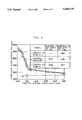
- FIG. 7 is a graph showing the distribution of remaining stress in the preferred embodiment and the comparative examples.
- FIG. 8 is a graph showing the result of fatigue test in the comparative example 1.
- FIG. 9 is a graph showing the results of fatigue test in the preferred embodiment and the comparative example 2.
- the wire (SWACX-V) for spring used in the present preferred embodiment is the alloy steel comprising carbon in an amount of 0.64% by weight (Hereinafter, % means % by weight if it is not specified particularly.) silicon in an amount of 1.43%, manganese in an amount of 0.67%, phosphorous in an amount of 0.015%, sulfur in an amount of 0.006%, chromium in an amount of 1.57%, molybdenum in an amount of 0.57%. vanadium in an amount of 0.26% and the balance of iron.
- the alloy steel was subjected to flaw working, hot rolling, peeling, and annealing, the alloy steel was subjected to cold drawing, oil quenching and tempering and hot tempering so as to get the annealed wire.
- This annealed wire has the tensile strength ⁇ B being 1,570N/mm 2 and the surface of the wire is covered by the oxided scale.
- This annealed wire was subjected to cold coiling so as form the coil spring whose diameter is 3,2 mm; whose coil central diameter is 21,2 mm; whose total number of turns is 6.5 turns; whose effective number of turns is 4.5 turns; whose free length is 52 mm; and whose spring constant is 23.54N/mm 2 .
- the wire was hardened at the temperature of 880° C. for 30 minutes and it was tempered at the temperature of 435° C. for 60 minutes by heated gas.
- the bearing surface was subjected to grinding. This coil whose bearing surface was ground was subjected to the gas nitriding treatment under the atmosphere of ammonia gas at the temperature of 435° C. for 24 hours. Therefore, the nitriding surface was formed on the surface of the coil.
- the wire was subjected the high strength two-stage shot peening.
- a shot ball of ⁇ 0.8RCW and Hv720 was used and the shot peening of the impeller projection (for 30 minutes) was conducted under the condition of 70 m/s.
- the second stage of shot peening was conducted.
- a shot ball of ⁇ 0.25RCW and Hv800 was used and the shot peening was conducted under the condition of air projection pressure being 0.5 MPa (for 30 minutes).
- the wire was subjected to the cold or low temperature annealing at the temperature of 225° C. for 30 minutes, the inside distortion which is extraordinary large was removed and the compressed remaining stress was given on the coil surface so that the coil spring of the present preferred embodiment was obtained.
- SWOSC-V steel of JIS standard instead of alloy steel which was used in the preferred embodiment, SWOSC-V steel of JIS standard is used.
- the SWOSC-V percent by weight, comprises carbon in an amount of 0.56%, silicon in an amount of 1.42%, manganese in an amount of 0.65%, phosphorous in an amount of 0.008%, sulfur in an amount of 0.009%, chromium in an amount of 0.67% and the balance of iron.
- the SWOSC-V steel was cold drawn and then, it was hardened and tempered so that the alloy steel oil hardened and tempered wire whose tensile strength ⁇ B is 1,950N/mm 2 was used. And after passing through the next process, the coil spring was produced.
- this oil hardened and tempered wire was subjected to the cold annealing, at the temperature of 425° C. for 30 minutes, as a substitute for the hardening and tempering in the above-mentioned preferred embodiment.
- the bearing surface was subjected to grinding.
- the shot peening was conducted by using the shot ball of ⁇ 0.8RCW and Hv550 under the condition of impeller projection at the speed of 70 m/s.
- the cold annealing was conducted at the temperature of 225° C. for 30 minutes.
- This comparative example 2 uses the same alloy steel as that of the preferred embodiment.
- the alloy steel was subjected to the cold drawing; the hardening and tempering treatment; and the low temperature annealing so that wire whose tensile strengthen ⁇ B 1,570N/mm 2 and which is the same as that of the preferred embodiment was used.
- the shot peening was conducted by using the shot ball of ⁇ 0.8RCW and Hv550 under the impeller projection at the speed of 70 m/s.
- the coil spring was produced by the same method of that of the preferred embodiment except changing the condition of shot peening. In thus obtained coil spring, the peak value and the crossing point of the remaining stress and the surface roughness of the coil spring were investigated.
- the reference value the value of the coil spring which is not subjected to the shot peening but which is only subjected to nitriding was used.
- FIGS. 1 to 3 the projection conditions of the first stage in the high strength two-stage shot peening were changed.
- FIGS. 1 to 3 show the effect of the hardness of the shot ball and the projection speed based on the investigation of the peak value, crossing point and surface roughness.
- FIG. 2 shows the relationship between the crossing point and the projection speed of the shot ball. If the hardness Hv of the shot ball is 550, the crossing point doesn't become deeper compared to that of 720 which is in the extent ranging from 650 to 850 in the present invention even if the projection speed is increased so that there is little effect in this case.
- FIG. 3 shows the relationship between the surface roughness and the projection speed. If the projection speed of the shot ball is 130 m/s, the surface of the treated material becomes too rough. However until the projection speed is 120 m/s, the roughness Rz is almost constant.
- FIGS. 4 and 5 show: the relationship between the projection speed of the shot at the second stage and the remaining stress peak value; and the relationship between the projection condition of the shot at the second stage and the remaining stress peak value respectively.
- peak value is not increased if the speed is not less than 100 m/s. If the speed is not less than 100 m/s, it is hard to conduct the continuous operation with regard to the equipment.
- the air projection is effective because the change in the peak value is little in response to the change in pressure.
- the preferred embodiment shows Hv572 and the comparative example 1 shows Hv548.
- the preferred embodiment shows Hv572
- comparative example 1 shows Hv527
- the comparative example 2 shows Hv580.
- the comparative example 2 and the preferred embodiment of the SXACX-V steel show the improved hardness to the great extent near the surface thereof.
- FIG. 7 the relationship between the remaining stress (MPa) of the coil spring in the present preferred embodiment and the depth from the surface thereof is shown by using ⁇ and continuous line.
- the relationships between the remaining stress (MPa) of the coil springs in the comparative examples 1 and 2 and the depth from the surface are shown by using ⁇ , ⁇ and continuous line respectively.
- the coil spring which is subjected the high strength two-stage shot peening in the preferred embodiment shows larger amount of remaining stress at the surface compared with that of the coil springs in the comparative examples.
- the endurance limit ⁇ m of the coil spring which was produced by the present preferred embodiment is 687 (average stress) ⁇ 560 MPa (FIG. 9).
- the endurance limit ⁇ m of the coil spring produced by the comparative example 1 is 589 (average stress) ⁇ 415 MPa (FIG. 8) and the endurance limit ⁇ m of the coil spring produced by the comparative example 2 is 687 (average stress) ⁇ 505 MPa (FIG. 9).
- the big difference between the endurance limit of the coil spring in the comparative example 1 and the endurance limit of the coil spring in the comparative example 2 is due to the fact that there is difference in the alloy steel composition and that the nitriding treatment is conducted or not. It is assumed that the difference of endurance limit between the coil spring of the present preferred embodiment and the coil spring of the comparative example 2 is due to the effect caused by the fact that the coil spring of the present preferred embodiment is subjected to the high strength two-stage shot peening.
Landscapes
- Chemical & Material Sciences (AREA)
- Engineering & Computer Science (AREA)
- Mechanical Engineering (AREA)
- Organic Chemistry (AREA)
- Materials Engineering (AREA)
- Metallurgy (AREA)
- Crystallography & Structural Chemistry (AREA)
- General Engineering & Computer Science (AREA)
- Chemical Kinetics & Catalysis (AREA)
- Physics & Mathematics (AREA)
- Thermal Sciences (AREA)
- Wire Processing (AREA)
- Springs (AREA)
- Heat Treatment Of Steel (AREA)
- Heat Treatment Of Articles (AREA)
Applications Claiming Priority (2)
| Application Number | Priority Date | Filing Date | Title |
|---|---|---|---|
| JP17712194A JP3173756B2 (ja) | 1994-07-28 | 1994-07-28 | コイルばねの製造方法 |
| JP6-177121 | 1994-07-28 |
Publications (1)
| Publication Number | Publication Date |
|---|---|
| US5665179A true US5665179A (en) | 1997-09-09 |
Family
ID=16025537
Family Applications (1)
| Application Number | Title | Priority Date | Filing Date |
|---|---|---|---|
| US08/507,926 Expired - Lifetime US5665179A (en) | 1994-07-28 | 1995-07-27 | Process for producing a coil spring |
Country Status (4)
| Country | Link |
|---|---|
| US (1) | US5665179A (ja) |
| EP (1) | EP0694621B1 (ja) |
| JP (1) | JP3173756B2 (ja) |
| DE (1) | DE69513236T2 (ja) |
Cited By (17)
| Publication number | Priority date | Publication date | Assignee | Title |
|---|---|---|---|---|
| US5897717A (en) * | 1997-03-12 | 1999-04-27 | Nippon Steel Corporation | High strength spring steel and process for producing same |
| US6022427A (en) * | 1997-02-08 | 2000-02-08 | Fried Krupp | Method for producing helical springs |
| US6024346A (en) * | 1995-10-20 | 2000-02-15 | Nhk Spring Co., Ltd. | Coil spring resistant to permanent set and fatigue |
| US6027577A (en) * | 1997-03-12 | 2000-02-22 | Chuo Hatsujo Kabushiki Kaisha | Manufacturing method of valve spring superior in durability |
| US6224686B1 (en) * | 1998-02-27 | 2001-05-01 | Chuo Hatsujo Kabushiki Kaisha | High-strength valve spring and it's manufacturing method |
| KR100323468B1 (ko) * | 1999-09-02 | 2002-02-06 | 허영준 | 높은 피로 저항성을 갖는 엔진 밸브 스프링을 제작할 수 있는 방법 |
| US6346157B1 (en) * | 1999-03-31 | 2002-02-12 | Showa Corp. | Manufacturing method of suspension spring for car |
| US20030024610A1 (en) * | 2000-12-20 | 2003-02-06 | Nobuhiko Ibakaki | Steel wire rod for hard drawn spring,drawn wire rod for hard drawn spring and hard drawn spring, and method for producing hard drawn spring |
| US20040079067A1 (en) * | 2002-03-18 | 2004-04-29 | Chuo Hatsujo Kabushiki Kaisha | Oil tempered wire for cold forming coil springs |
| US6790294B1 (en) * | 1999-02-19 | 2004-09-14 | Suncall Corporation | Spring with excellent fatigue endurance property and surface treatment method for producing the spring |
| US20050069842A1 (en) * | 1997-03-18 | 2005-03-31 | Schleppenbach David A. | Apparatus and methods for a shape memory spring actuator and display |
| US20060171822A1 (en) * | 2000-10-17 | 2006-08-03 | Seagar Neville D | Linear compressor |
| US20070289350A1 (en) * | 2006-06-12 | 2007-12-20 | Kabushiki Kaisha Kobe Seiko Sho (Kobe Steel, Ltd.) | Flat wire manufacturing method of manufacturing flat wire for ring gear |
| US20090188501A1 (en) * | 2004-08-30 | 2009-07-30 | Forsyth David E | Self Contained Breathing Apparatus Modular Control System |
| US20130125600A1 (en) * | 2010-07-27 | 2013-05-23 | Yuji Kobayashi | Method for shot-peening and a shot-peening machine |
| US20160208875A1 (en) * | 2013-10-28 | 2016-07-21 | Chuo Hatsujo Kabushiki Kaisha | Spring and method for manufacturing the spring |
| EP2484493B1 (en) * | 2009-09-30 | 2021-01-20 | Sintokogio, Ltd. | Shot peening treatment method for steel product |
Families Citing this family (12)
| Publication number | Priority date | Publication date | Assignee | Title |
|---|---|---|---|---|
| FR2764219B1 (fr) * | 1997-06-04 | 1999-07-16 | Ascometal Sa | Procede de fabrication d'un ressort en acier, ressort obtenu et acier pour la fabrication d'un tel ressort |
| ES2190562T3 (es) * | 1998-10-02 | 2003-08-01 | Thyssen Krupp Automotive Ag | Procedimiento para fabricar muelles helicoidales. |
| BR0011428A (pt) * | 1999-06-08 | 2002-03-26 | Nhk Spring Co Ltd | Mola altamente reforçada e processo para produzir a mesma |
| DE10032313A1 (de) * | 2000-07-04 | 2002-01-17 | Bosch Gmbh Robert | Schraubenfedern aus legiertem Stahl und Verfahren zum Herstellen solcher Schraubenfedern |
| US20020104587A1 (en) * | 2001-02-02 | 2002-08-08 | Leo Medeiros | Method for nitriding suspension components |
| CA2597266A1 (en) | 2005-02-16 | 2006-08-24 | Mitsubishi Heavy Industries, Ltd. | Surface treatment method of titanium alloy member for aerospace equipment |
| DE102009008285A1 (de) * | 2009-02-10 | 2010-11-25 | Gebr. Schmachtenberg Gmbh | Stahllegierung |
| EP2322819A1 (de) * | 2009-11-12 | 2011-05-18 | Benteler Stahl/Rohr Gmbh | Federelement und Verfahren zur Herstellung eines Federlements |
| WO2014209283A1 (en) * | 2013-06-25 | 2014-12-31 | Kalt Manufacturing Co. | Improved tool durability methods |
| DE112020000034T5 (de) * | 2019-07-01 | 2022-03-24 | Sumitomo Electric Industries, Ltd. | Stahldraht und Feder |
| CN112276483B (zh) * | 2020-09-27 | 2022-02-11 | 瑞安市优赛车辆配件有限公司 | 一种汽车变速箱用加强型卡环生产工艺 |
| DE102021130879A1 (de) | 2021-11-25 | 2023-05-25 | Schaeffler Technologies AG & Co. KG | Schraubendruckfeder, insbesondere für eine Drehschwingungsisolationseinrichtung und Verfahren zu deren Herstellung |
Citations (5)
| Publication number | Priority date | Publication date | Assignee | Title |
|---|---|---|---|---|
| US3073022A (en) * | 1959-04-03 | 1963-01-15 | Gen Motors Corp | Shot-peening treatments |
| GB2210299A (en) * | 1987-09-25 | 1989-06-07 | Nissan Motor | High strength spring |
| JPH04247824A (ja) * | 1991-01-25 | 1992-09-03 | Nippon Steel Corp | 高強度ばねの製造方法 |
| JPH05179348A (ja) * | 1991-07-11 | 1993-07-20 | Tougou Seisakusho:Kk | 熱間コイリングによるコイルばねの製造方法 |
| JPH05339763A (ja) * | 1991-02-04 | 1993-12-21 | Tougou Seisakusho:Kk | コイルばねの製造方法 |
Family Cites Families (9)
| Publication number | Priority date | Publication date | Assignee | Title |
|---|---|---|---|---|
| JPS5913568B2 (ja) * | 1978-04-28 | 1984-03-30 | 高周波熱錬株式会社 | 冷間成形コイルばねの製造方法 |
| JPS59133350A (ja) * | 1983-10-12 | 1984-07-31 | High Frequency Heattreat Co Ltd | 高強靭ばね用鋼材 |
| JP2511663B2 (ja) * | 1987-01-14 | 1996-07-03 | 本田技研工業株式会社 | コイルスプリングの製造方法 |
| JPH01177318A (ja) * | 1987-12-30 | 1989-07-13 | Nippon Steel Corp | 疲労強度のすぐれたコイルばねの製造方法 |
| JP2610965B2 (ja) * | 1988-10-15 | 1997-05-14 | 新日本製鐵株式会社 | 高疲労強度ばね鋼 |
| JP2790303B2 (ja) * | 1989-02-17 | 1998-08-27 | 新日本製鐵株式会社 | 高疲労強度ばねの製造方法及びそれに用いる鋼線 |
| JP3045795B2 (ja) * | 1991-03-12 | 2000-05-29 | 鈴木金属工業株式会社 | 高強度ばね及びその製造に用いるばね用オイルテンパー線 |
| JPH05148537A (ja) * | 1991-07-11 | 1993-06-15 | Tougou Seisakusho:Kk | コイルばねの製造方法 |
| JP2994508B2 (ja) * | 1991-11-26 | 1999-12-27 | 株式会社東郷製作所 | コイルばねの製造方法 |
-
1994
- 1994-07-28 JP JP17712194A patent/JP3173756B2/ja not_active Expired - Fee Related
-
1995
- 1995-07-27 US US08/507,926 patent/US5665179A/en not_active Expired - Lifetime
- 1995-07-28 DE DE69513236T patent/DE69513236T2/de not_active Expired - Fee Related
- 1995-07-28 EP EP95111930A patent/EP0694621B1/en not_active Expired - Lifetime
Patent Citations (5)
| Publication number | Priority date | Publication date | Assignee | Title |
|---|---|---|---|---|
| US3073022A (en) * | 1959-04-03 | 1963-01-15 | Gen Motors Corp | Shot-peening treatments |
| GB2210299A (en) * | 1987-09-25 | 1989-06-07 | Nissan Motor | High strength spring |
| JPH04247824A (ja) * | 1991-01-25 | 1992-09-03 | Nippon Steel Corp | 高強度ばねの製造方法 |
| JPH05339763A (ja) * | 1991-02-04 | 1993-12-21 | Tougou Seisakusho:Kk | コイルばねの製造方法 |
| JPH05179348A (ja) * | 1991-07-11 | 1993-07-20 | Tougou Seisakusho:Kk | 熱間コイリングによるコイルばねの製造方法 |
Non-Patent Citations (10)
| Title |
|---|
| English language abstract of Japanese Patent No. JP A 02 107746, from Patent Abstracts of Japan, vol. 14, No. 314 (Jul. 1990). * |
| English language abstract of Japanese Patent No. JP A 04 285142, from Patent Abstracts of Japan, vol. 17, No. 93 (Feb. 1993). * |
| English language abstract of Japanese Patent No. JP A 05 148537, from Patent Abstracts of Japan, vol. 17, No. 540 (Sep. 1993). * |
| English language abstract of Japanese Patent No. JP A 05 177544, from Patent Abstracts of Japan, vol. 17, No. 595 (Oct. 1993). * |
| English language abstract of Japanese Patent No. JP A 63 176430, from Patent Abstracts of Japan, vol. 12, No. 450 (Nov. 1988). * |
| English-language abstract of Japanese Patent No. JP-A-02-107746, from Patent Abstracts of Japan, vol. 14, No. 314 (Jul. 1990). |
| English-language abstract of Japanese Patent No. JP-A-04-285142, from Patent Abstracts of Japan, vol. 17, No. 93 (Feb. 1993). |
| English-language abstract of Japanese Patent No. JP-A-05-148537, from Patent Abstracts of Japan, vol. 17, No. 540 (Sep. 1993). |
| English-language abstract of Japanese Patent No. JP-A-05-177544, from Patent Abstracts of Japan, vol. 17, No. 595 (Oct. 1993). |
| English-language abstract of Japanese Patent No. JP-A-63-176430, from Patent Abstracts of Japan, vol. 12, No. 450 (Nov. 1988). |
Cited By (24)
| Publication number | Priority date | Publication date | Assignee | Title |
|---|---|---|---|---|
| US6024346A (en) * | 1995-10-20 | 2000-02-15 | Nhk Spring Co., Ltd. | Coil spring resistant to permanent set and fatigue |
| US6022427A (en) * | 1997-02-08 | 2000-02-08 | Fried Krupp | Method for producing helical springs |
| US6027577A (en) * | 1997-03-12 | 2000-02-22 | Chuo Hatsujo Kabushiki Kaisha | Manufacturing method of valve spring superior in durability |
| US5897717A (en) * | 1997-03-12 | 1999-04-27 | Nippon Steel Corporation | High strength spring steel and process for producing same |
| US7018209B2 (en) * | 1997-03-18 | 2006-03-28 | Purdue Research Foundation | Apparatus and methods for a shape memory spring actuator and display |
| US20050069842A1 (en) * | 1997-03-18 | 2005-03-31 | Schleppenbach David A. | Apparatus and methods for a shape memory spring actuator and display |
| US6224686B1 (en) * | 1998-02-27 | 2001-05-01 | Chuo Hatsujo Kabushiki Kaisha | High-strength valve spring and it's manufacturing method |
| US6790294B1 (en) * | 1999-02-19 | 2004-09-14 | Suncall Corporation | Spring with excellent fatigue endurance property and surface treatment method for producing the spring |
| US6346157B1 (en) * | 1999-03-31 | 2002-02-12 | Showa Corp. | Manufacturing method of suspension spring for car |
| KR100323468B1 (ko) * | 1999-09-02 | 2002-02-06 | 허영준 | 높은 피로 저항성을 갖는 엔진 밸브 스프링을 제작할 수 있는 방법 |
| US9605666B2 (en) * | 2000-10-17 | 2017-03-28 | Fisher & Paykel Appliances Limited | Linear compressor |
| US20060171822A1 (en) * | 2000-10-17 | 2006-08-03 | Seagar Neville D | Linear compressor |
| US20030024610A1 (en) * | 2000-12-20 | 2003-02-06 | Nobuhiko Ibakaki | Steel wire rod for hard drawn spring,drawn wire rod for hard drawn spring and hard drawn spring, and method for producing hard drawn spring |
| US7074282B2 (en) * | 2000-12-20 | 2006-07-11 | Kabushiki Kaisha Kobe Seiko Sho | Steel wire rod for hard drawn spring, drawn wire rod for hard drawn spring and hard drawn spring, and method for producing hard drawn spring |
| US20050161131A1 (en) * | 2001-06-07 | 2005-07-28 | Chuo Hatsujo Kabushiki Kaisaha | Oil tempered wire for cold forming coil springs |
| US7407555B2 (en) | 2001-06-07 | 2008-08-05 | Chuo Hatsujo Kabushiki Kaisha | Oil tempered wire for cold forming coil springs |
| US20040079067A1 (en) * | 2002-03-18 | 2004-04-29 | Chuo Hatsujo Kabushiki Kaisha | Oil tempered wire for cold forming coil springs |
| US20090188501A1 (en) * | 2004-08-30 | 2009-07-30 | Forsyth David E | Self Contained Breathing Apparatus Modular Control System |
| US20070289350A1 (en) * | 2006-06-12 | 2007-12-20 | Kabushiki Kaisha Kobe Seiko Sho (Kobe Steel, Ltd.) | Flat wire manufacturing method of manufacturing flat wire for ring gear |
| US8448488B2 (en) * | 2006-06-12 | 2013-05-28 | Kobe Steel, Ltd. | Flat wire manufacturing method of manufacturing flat wire for ring gear |
| EP2484493B1 (en) * | 2009-09-30 | 2021-01-20 | Sintokogio, Ltd. | Shot peening treatment method for steel product |
| US9073176B2 (en) * | 2010-07-27 | 2015-07-07 | Sintokogio, Ltd. | Method for shot-peening and a shot-peening machine |
| US20130125600A1 (en) * | 2010-07-27 | 2013-05-23 | Yuji Kobayashi | Method for shot-peening and a shot-peening machine |
| US20160208875A1 (en) * | 2013-10-28 | 2016-07-21 | Chuo Hatsujo Kabushiki Kaisha | Spring and method for manufacturing the spring |
Also Published As
| Publication number | Publication date |
|---|---|
| DE69513236T2 (de) | 2000-07-13 |
| JP3173756B2 (ja) | 2001-06-04 |
| EP0694621B1 (en) | 1999-11-10 |
| JPH0841533A (ja) | 1996-02-13 |
| DE69513236D1 (de) | 1999-12-16 |
| EP0694621A1 (en) | 1996-01-31 |
Similar Documents
| Publication | Publication Date | Title |
|---|---|---|
| US5665179A (en) | Process for producing a coil spring | |
| KR100711370B1 (ko) | 가공성이 우수한 고강도 스프링용 강선 및 고강도 스프링 | |
| US7763123B2 (en) | Spring produced by a process comprising coiling a hard drawn steel wire excellent in fatigue strength and resistance to setting | |
| KR20000028786A (ko) | 고강도 스프링용 강선 및 그 제조 방법 | |
| KR100682150B1 (ko) | 경인발스프링용 강선재, 경인발스프링용 신선재와 경인발스프링 및 경인발스프링의 제조방법 | |
| CN112292471B (zh) | 机械部件 | |
| JP2003105498A (ja) | 高強度ばねおよびその製造方法 | |
| JP4097151B2 (ja) | 加工性に優れた高強度ばね用鋼線および高強度ばね | |
| JP2009052144A (ja) | 高強度ばね | |
| JP2650225B2 (ja) | ばね用鋼 | |
| JP7436779B2 (ja) | 浸炭歯車用鋼、浸炭歯車及び浸炭歯車の製造方法 | |
| JP3872364B2 (ja) | 冷間成形コイルばね用オイルテンパー線の製造方法 | |
| JPH04247824A (ja) | 高強度ばねの製造方法 | |
| JP3930715B2 (ja) | 高強度ばね | |
| JP2002180199A (ja) | 耐へたり性に優れたばね用鋼およびばね用鋼線並びにばね | |
| JP3476097B2 (ja) | 浸炭用鋼および浸炭部材 | |
| JPH09279296A (ja) | 冷間鍛造性に優れた軟窒化用鋼 | |
| JP2005120479A (ja) | 高強度ばねおよびその製造方法 | |
| CN114555849B (zh) | 钢线 | |
| US5643532A (en) | Corrosion-resistant spring steel | |
| CN115298338B (zh) | 钢线 | |
| JP3142689B2 (ja) | 疲労強度の優れたばね | |
| JP3541013B2 (ja) | 優れた接触疲労特性を有する動力伝達部品用鋼 | |
| JP7368697B2 (ja) | 浸炭歯車用鋼、浸炭歯車及び浸炭歯車の製造方法 | |
| JP3607583B2 (ja) | 動力伝達部品用鋼および動力伝達部品 |
Legal Events
| Date | Code | Title | Description |
|---|---|---|---|
| AS | Assignment |
Owner name: TOGO SEISAKUSHO CORPORATION, JAPAN Free format text: ASSIGNMENT OF ASSIGNORS INTEREST;ASSIGNORS:IZAWA, YOSHINOBU;KONDO, SATORU;YARITA, HIROSHI;REEL/FRAME:007733/0971 Effective date: 19950904 Owner name: SUZUKI METAL INDUSTRY CO., LTD., JAPAN Free format text: ASSIGNMENT OF ASSIGNORS INTEREST;ASSIGNORS:IZAWA, YOSHINOBU;KONDO, SATORU;YARITA, HIROSHI;REEL/FRAME:007733/0971 Effective date: 19950904 |
|
| STCF | Information on status: patent grant |
Free format text: PATENTED CASE |
|
| FEPP | Fee payment procedure |
Free format text: PAYOR NUMBER ASSIGNED (ORIGINAL EVENT CODE: ASPN); ENTITY STATUS OF PATENT OWNER: LARGE ENTITY |
|
| FPAY | Fee payment |
Year of fee payment: 4 |
|
| FPAY | Fee payment |
Year of fee payment: 8 |
|
| FPAY | Fee payment |
Year of fee payment: 12 |