US5580477A - Electric power supply for a heater heating a catalyst for purifying automotive exhaust gases - Google Patents
Electric power supply for a heater heating a catalyst for purifying automotive exhaust gases Download PDFInfo
- Publication number
- US5580477A US5580477A US08/263,426 US26342694A US5580477A US 5580477 A US5580477 A US 5580477A US 26342694 A US26342694 A US 26342694A US 5580477 A US5580477 A US 5580477A
- Authority
- US
- United States
- Prior art keywords
- heater
- condenser
- switch
- electric power
- power supply
- Prior art date
- Legal status (The legal status is an assumption and is not a legal conclusion. Google has not performed a legal analysis and makes no representation as to the accuracy of the status listed.)
- Expired - Fee Related
Links
Images

Classifications
-
- F—MECHANICAL ENGINEERING; LIGHTING; HEATING; WEAPONS; BLASTING
- F01—MACHINES OR ENGINES IN GENERAL; ENGINE PLANTS IN GENERAL; STEAM ENGINES
- F01N—GAS-FLOW SILENCERS OR EXHAUST APPARATUS FOR MACHINES OR ENGINES IN GENERAL; GAS-FLOW SILENCERS OR EXHAUST APPARATUS FOR INTERNAL COMBUSTION ENGINES
- F01N3/00—Exhaust or silencing apparatus having means for purifying, rendering innocuous, or otherwise treating exhaust
- F01N3/08—Exhaust or silencing apparatus having means for purifying, rendering innocuous, or otherwise treating exhaust for rendering innocuous
- F01N3/10—Exhaust or silencing apparatus having means for purifying, rendering innocuous, or otherwise treating exhaust for rendering innocuous by thermal or catalytic conversion of noxious components of exhaust
- F01N3/18—Exhaust or silencing apparatus having means for purifying, rendering innocuous, or otherwise treating exhaust for rendering innocuous by thermal or catalytic conversion of noxious components of exhaust characterised by methods of operation; Control
- F01N3/20—Exhaust or silencing apparatus having means for purifying, rendering innocuous, or otherwise treating exhaust for rendering innocuous by thermal or catalytic conversion of noxious components of exhaust characterised by methods of operation; Control specially adapted for catalytic conversion ; Methods of operation or control of catalytic converters
- F01N3/2006—Periodically heating or cooling catalytic reactors, e.g. at cold starting or overheating
- F01N3/2013—Periodically heating or cooling catalytic reactors, e.g. at cold starting or overheating using electric or magnetic heating means
-
- Y—GENERAL TAGGING OF NEW TECHNOLOGICAL DEVELOPMENTS; GENERAL TAGGING OF CROSS-SECTIONAL TECHNOLOGIES SPANNING OVER SEVERAL SECTIONS OF THE IPC; TECHNICAL SUBJECTS COVERED BY FORMER USPC CROSS-REFERENCE ART COLLECTIONS [XRACs] AND DIGESTS
- Y02—TECHNOLOGIES OR APPLICATIONS FOR MITIGATION OR ADAPTATION AGAINST CLIMATE CHANGE
- Y02T—CLIMATE CHANGE MITIGATION TECHNOLOGIES RELATED TO TRANSPORTATION
- Y02T10/00—Road transport of goods or passengers
- Y02T10/10—Internal combustion engine [ICE] based vehicles
- Y02T10/12—Improving ICE efficiencies
Definitions
- This invention relates to an electric power supply for a heater, in particular relates to an electric power supply for a heater heating a catalyst for the use of purifying exhaust gas from an internal combustion engine of the vehicle.
- Catalyst for the use of purifying exhaust gas from an internal combustion engine is not usually activated under a predetermined value of temperature so as not to be able to purify the exhaust gas.
- the catalyst without the heater is heated by heat of the exhaust gas. Therefore, since the exhaust gas is low temperature and the inner portion of the internal combustion engine is not heated when the internal combustion engine is started, the catalyst can not sufficiently purify the exhaust gas.
- a conventional catalytic device which comprises a heater coated with the catalyst is disclosed in the Japanese Patent Laid Open No. 48 (1973)-54312.
- ingredients not burned in the exhaust gas are evaporated by the heater when-the engine is started.
- the catalytic device because a large amount of the rush current (which will be described "electric current” hereinafter) is flowed from a battery activating the heater when the heater is heated, the battery has a short life. Further, the battery has to include a large capacity.
- a conventional electric power supply for a heater heating a catalyst is disclosed in the Japanese Patent Laid Open No. 4 (1992)-276111.
- the electric power supply in the prior art comprises a charged condenser used for the power supply to the heater.
- the charged condenser is charged up to the same voltage of the battery by the battery directly. Therefore, the electric current is not flowed from the battery activating the heater when the heater is heated. Further, early in the activation of the heater the condenser can flow a large electric current into the heater relative to the battery. Consequently, the electric power supply can rapidly heat the catalyst.
- the heater is heated by the voltage of the battery, a large amount of the electric current has to be flowed into the heater so as to heat the catalyst when the condenser is charged by the battery. Therefore, the voltage applied to the heater is decreased through a cable and switches and so on. Furthermore, the electric power supply has to be large in size, heavy in weight and high in cost.
- the electric power supply including two heaters each of heating two catalysts provided to be in parallel each other so as to be arranged with the exhaust passage, a large amount of electric current is flowed into the heaters from the battery because of the low resistance of the heaters. Therefore, the cable and the switches are required to be used for a large electric current exclusively.
- an electric power supply for a heater in accordance with this invention comprises a heater, a battery electrically connected with the heater, a booster circuit electrically connected with the battery, a condenser disposed between the heater and the booster circuit and control means which control a charge and a discharge of the condenser.
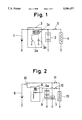
- FIG. 1 is a circuit diagram of a first embodiment of an electric power supply for a heater in accordance with the present invention
- FIG. 2 is a circuit diagram of a second embodiment of an electric power supply for a heater in accordance with the present invention.
- FIG. 3 is a circuit diagram of a third embodiment of an electric power supply for a heater in accordance with the present invention.
- FIG. 1 A first embodiment of an electric power supply for a heater in accordance with the present invention is disclosed in the FIG. 1.
- a battery i is used for supplying electric power to a starter of an internal combustion engine (not shown in the FIGURES) when the engine is started.
- a condenser 2 which includes a plurality of condenser elements is charged by the battery 1.
- the condenser 2 is used for a power resource of heating a heater 4 with a catalyst.
- a DC-DC converter 3 which is used for a booster circuit comprises a charge control switch 3a, diode 3b and a transformer 3c.
- the transformer 3c transforms a voltage of the battery 1 into 120 volt.
- the condenser 2 is charged by the transformed voltage.
- a switch 5 controls a discharge of the condenser 2.
- the switch 5 is provided to be closed for a predetermined period when the internal combustion engine is started.
- the battery 1 of 12 volt
- the condensers 2 of 3.0 farad and the heater 4 of 4.5 ohm are used.
- the catalyst needs an electric power from 15 to 40 kilojoule relative to a size of the catalyst to be heated.
- the condenser elements of the condenser 2 are arranged in series each other so as to be able to resist the high voltage transformed by the DC-DC converter 3.
- the condenser 2 is charged by the voltage of 120 volt transformed of the voltage of 12 volt of the battery 1.
- the switch 5 is closed and the heater 4 is heated by the electric current flowed from the condenser 2.
- a quantity of the electric current flowed into the heater 4 (In accordance with the embodiment of the invention, the electric current of 30 ampere is flowed into the heater 4.) is rather smaller than that of the conventional electric power supply (In the conventional electric power supply, the electric current of 150 ampere is flowed into the heater.) because the electric resistance of the heater 4 (In accordance with the embodiment of the invention, the electric resistance of the heater 4 is 4.5 ohm.) is extremely large in relation to that of the conventional electric power supply (In the conventional electric power supply, the electric resistance of the heater is 70 milliohm.).
- the switch 5 is closed when the internal combustion engine is started.
- the switch 5 does not have to be closed according to the start of the engine.
- the switch 5 may be closed when the an ignition key is inserted into a key cylinder.
- the close operation of the switch 5 may be connected with an open and a close operations of a vehicle door.
- the switch 5 may be closed when an increase of a voltage of the down stream of an ignition switch in a circuit is detected.
- the catalyst is begun to be heated late and the exhaust gas insufficiently purified. Therefore, the catalyst had better be heated by anticipation of the engine start before the engine is started.
- the heater 4 can be heated by the high voltage because of the DC-DC converter 3. Therefore the electric current flowed into the heater 4 can be small by the high voltage supplied to the heater 4 and the large resistance of the heater 4 since the electric power which the heater 4 needs to be heated is constant. Consequently, the voltage is not decreased through a cable and switches in the circuit. Further, the electric power supply can be small in size, light in weight and low in cost. Furthermore, because the condenser 2 is used for heating the heater 4 instead of the battery 1, the battery 1 can be eased the burden. And the condenser 2 supplies the electric power to the heater 4 more rapidly than the battery 1.
- a second embodiment of the electric power supply for a heater is disclosed in the FIG. 2.
- the electric power supply comprises a DC-DC converter 6 as a booster circuit including an inducter 6a.
- a voltage of a battery 8 is directly supplied to a condenser 7.
- a voltage of 40 volt which is formed to be transformed of the voltage of the battery 8 by the DC-DC converter 6 is supplied to a condenser 9 which includes a plurality of condenser elements.
- the condenser 7 of 100 farad and the condenser 9 of 30 farad are used.
- a switch 10 is selectively switched into one of a first position for charging the condenser 7 and a second position for charging the condenser 9.
- switches 11 and 12 are closed so as to heat a heater 13 by the condensers 7 and 9 respectively.
- the switch 11 is switched to be closed when the engine is started.
- the switch 11 is opened when a predetermined time is passed after the switch 11 is closed.
- the switch 12 is closed after the switch 11 is closed. Later, the switch 12 is switched to be opened after the heater 13 is sufficiently heated by the discharges of the condensers 7 and 9.
- each of the condensers-7 and 9 is charged by the selective operation of the switch 10.
- the switch 11 is closed and the heater 13 with the catalyst is heated by the electric current flowed from the condenser 7.
- an electric current of 150 ampere is flowed into the heater which has an electric resistance of 70 milliohm.
- the electric current of 30 ampere is flowed into the heater 13.
- the switch 11 is opened and the switch 12 is closed. Therefore, the heater 13 can be continued to be heated by the electric current flowed from the condenser 9 which is charged by the voltage formed to be transformed of the voltage of the battery 8 by the DC-DC converter 6.
- the electric resistance of the heater 13 is sufficiently large. Therefore, the electric current flowed into the heater 13 from the condenser 9 is not large.
- the condensers 7 and 9 are selectively switched to be applied to the heater 4, the rush current can be small when the catalyst is not heated. Therefore, the decreased voltage through the cable and switches can be further small.
- the vehicle for example, having a large displacement volume comprises two exhaust passages each of which is disposed at a right hand and a left hand of the vehicle, each of the exhaust passages includes a catalyst. Therefore, the vehicle has to comprise two heaters.
- the third embodiment can be corresponding to the vehicle above mentioned. As shown in the FIG. 3, since a circuit portion between heaters 16 and 17 is grounded, a piece of cable for ground of the heaters 16 and 17 can be omitted.
- the above structure of the heaters 16 and 17 is conventional. Therefore the third embodiment can be applied to the conventional electric power supply having two heaters.
- the electric power supply of the embodiment comprises a DC-DC converter 14 as a booster which includes a transformer 14a.
- a condenser 15 has a capacitance of 30 farad.
- Each of the heaters 16 and 17 has an electric resistance of 140 milliohm, which are composed into a resistance of 70 milliohm when the heaters 16 and 17 are arranged in parallel.
- a ground 18 used for discharging the condenser 15 is disposed between the heaters 16 and 17.
- a ground 19 used for charging the condenser 15 is disposed at a negative side of the condenser 15.
- a switch 21 is disposed between the ground 19 and the condenser 15.
- the condenser 15 is charged by the voltage of 40 volt transformed of the voltage of 12 volt of the battery 20 by the DC-DC converter 14.
- the switch 21 is closed.
- both the switches 22 and 23 are closed and the switch 21 is opened. Therefore, the heaters 16 and 17 are heated by the electric current flowed from the condensers 15.
- the electric current of 120 ampere is flowed into the heaters 16 and 17 Which are arranged in series.
- the electric current of 480 ampere is flowed into the heaters 16 and 17 when the heaters 16 and 17 are arranged in parallel. Consequently, the electric current flowed into the heaters 16 and 17 when the heaters 16 and 17 are arranged in series is smaller than the electric current when the heaters 16 and 17 are arranged in parallel.
- the above structure can be applied to the conventional two heaters having a ground which is connected the circuit portion between the heaters.
Applications Claiming Priority (2)
| Application Number | Priority Date | Filing Date | Title |
|---|---|---|---|
| JP5150377A JPH0711941A (ja) | 1993-06-22 | 1993-06-22 | ヒータ付触媒の電源装置 |
| JP5-150377 | 1993-06-22 |
Publications (1)
| Publication Number | Publication Date |
|---|---|
| US5580477A true US5580477A (en) | 1996-12-03 |
Family
ID=15495668
Family Applications (1)
| Application Number | Title | Priority Date | Filing Date |
|---|---|---|---|
| US08/263,426 Expired - Fee Related US5580477A (en) | 1993-06-22 | 1994-06-21 | Electric power supply for a heater heating a catalyst for purifying automotive exhaust gases |
Country Status (3)
| Country | Link |
|---|---|
| US (1) | US5580477A (de) |
| JP (1) | JPH0711941A (de) |
| DE (1) | DE4421066C2 (de) |
Cited By (7)
| Publication number | Priority date | Publication date | Assignee | Title |
|---|---|---|---|---|
| US5757164A (en) * | 1995-06-14 | 1998-05-26 | Toyota Jidosha Kabushiki Kaisha | Apparatus for supplying electric power to electrically heated catalysts attached to the exhaust gas passage of a vehicle |
| US6083369A (en) * | 1997-02-21 | 2000-07-04 | Toyota Jidosha Kabushiki Kaisha | Heater control system for an air-fuel ratio sensor in an internal combustion engine |
| US6951099B2 (en) | 2001-04-03 | 2005-10-04 | John Dickau | Heated insulated catalytic converter with air cooling |
| US9708954B2 (en) | 2011-07-20 | 2017-07-18 | Inergy Automotive Systems Research (Societe Anonyme) | Vehicular fluid injection system, controller and method for heating said fluid injection system |
| US10161277B2 (en) | 2017-04-24 | 2018-12-25 | GM Global Technology Operations LLC | Capacitor-powered catalyst heater |
| US11614014B2 (en) | 2020-12-10 | 2023-03-28 | Dr. Ing. H.C. F. Porsche Aktiengesellschaft | Apparatus for supplying voltage |
| US11674421B2 (en) * | 2019-06-19 | 2023-06-13 | Vitesco Technologies GmbH | Exhaust gas aftertreatment system and method for controlling an exhaust gas aftertreatment system of an internal combustion engine |
Families Citing this family (10)
| Publication number | Priority date | Publication date | Assignee | Title |
|---|---|---|---|---|
| JP3516361B2 (ja) * | 1995-01-17 | 2004-04-05 | 富士重工業株式会社 | 車両用電源装置 |
| DE19513490A1 (de) * | 1995-04-14 | 1996-10-17 | Roth Technik Gmbh | Beheizbarer Gassensor |
| ES2208792T3 (es) * | 1997-07-28 | 2004-06-16 | Siemens Aktiengesellschaft | Empleo de una mezcladora estatica como catalizador de hidrolisis, asi como su empleo en un conducto de gases de escape para una instalacion de combustion. |
| DE19754964A1 (de) * | 1997-12-11 | 1999-06-17 | Bayerische Motoren Werke Ag | Vorrichtung zur Energieversorgung eines Kraftfahrzeuges |
| DE19933654A1 (de) * | 1999-07-17 | 2001-01-18 | Audi Ag | Anordnung zum elektrischen Beheizen eines Katalysators |
| DE19940802B4 (de) * | 1999-08-27 | 2004-10-21 | Audi Ag | Anordnung zum elektrischen Beheizen eines Katalysators |
| JP2012065503A (ja) * | 2010-09-17 | 2012-03-29 | Toyota Motor Corp | 車両用電源装置 |
| JP2013103557A (ja) * | 2011-11-11 | 2013-05-30 | Denso Corp | 電力供給装置 |
| DE102019209207A1 (de) * | 2019-06-26 | 2020-12-31 | Vitesco Technologies GmbH | Abgasnachbehandlungssystem und Verfahren zur Steuerung eines Abgasnachbehandlungssystems eines Verbrennungsmotors |
| US10914212B1 (en) | 2019-10-29 | 2021-02-09 | Vitesco Technologies USA, LLC | 48V electrically heated catalyst system for a vehicle |
Citations (7)
| Publication number | Priority date | Publication date | Assignee | Title |
|---|---|---|---|---|
| JPS4854312A (de) * | 1971-11-11 | 1973-07-31 | ||
| US4651020A (en) * | 1985-09-10 | 1987-03-17 | Westinghouse Electric Corp. | Redundant power supply system |
| DE3805256A1 (de) * | 1988-02-19 | 1989-08-31 | Siemens Ag | Reserveschaltung zur notstromversorgung eines verbrauchers in einem fahrzeug |
| JPH04276111A (ja) * | 1991-03-04 | 1992-10-01 | Toyota Motor Corp | ヒータ付触媒の電源装置 |
| US5321231A (en) * | 1992-01-24 | 1994-06-14 | General Motors Corporation | System for supplying power to an electrically heated catalyst |
| US5319929A (en) * | 1988-05-20 | 1994-06-14 | W. R. Grace & Co.-Conn. | Catalytic converter system |
| EP0533037B1 (de) * | 1991-09-18 | 1996-04-10 | MAGNETI MARELLI S.p.A. | Elektrisches System für ein Kraftfahrzeug, mit mindestens einem einbegriffenen Superkondensator |
-
1993
- 1993-06-22 JP JP5150377A patent/JPH0711941A/ja active Pending
-
1994
- 1994-06-16 DE DE4421066A patent/DE4421066C2/de not_active Expired - Fee Related
- 1994-06-21 US US08/263,426 patent/US5580477A/en not_active Expired - Fee Related
Patent Citations (7)
| Publication number | Priority date | Publication date | Assignee | Title |
|---|---|---|---|---|
| JPS4854312A (de) * | 1971-11-11 | 1973-07-31 | ||
| US4651020A (en) * | 1985-09-10 | 1987-03-17 | Westinghouse Electric Corp. | Redundant power supply system |
| DE3805256A1 (de) * | 1988-02-19 | 1989-08-31 | Siemens Ag | Reserveschaltung zur notstromversorgung eines verbrauchers in einem fahrzeug |
| US5319929A (en) * | 1988-05-20 | 1994-06-14 | W. R. Grace & Co.-Conn. | Catalytic converter system |
| JPH04276111A (ja) * | 1991-03-04 | 1992-10-01 | Toyota Motor Corp | ヒータ付触媒の電源装置 |
| EP0533037B1 (de) * | 1991-09-18 | 1996-04-10 | MAGNETI MARELLI S.p.A. | Elektrisches System für ein Kraftfahrzeug, mit mindestens einem einbegriffenen Superkondensator |
| US5321231A (en) * | 1992-01-24 | 1994-06-14 | General Motors Corporation | System for supplying power to an electrically heated catalyst |
Cited By (8)
| Publication number | Priority date | Publication date | Assignee | Title |
|---|---|---|---|---|
| US5757164A (en) * | 1995-06-14 | 1998-05-26 | Toyota Jidosha Kabushiki Kaisha | Apparatus for supplying electric power to electrically heated catalysts attached to the exhaust gas passage of a vehicle |
| US6083369A (en) * | 1997-02-21 | 2000-07-04 | Toyota Jidosha Kabushiki Kaisha | Heater control system for an air-fuel ratio sensor in an internal combustion engine |
| DE19807345B4 (de) * | 1997-02-21 | 2005-02-03 | Toyota Jidosha Kabushiki Kaisha, Toyota | Erwärmungsvorrichtungssteuersystem für einen Luft/Kraftstoffverhältnissensor in einer Brennkraftmaschine |
| US6951099B2 (en) | 2001-04-03 | 2005-10-04 | John Dickau | Heated insulated catalytic converter with air cooling |
| US9708954B2 (en) | 2011-07-20 | 2017-07-18 | Inergy Automotive Systems Research (Societe Anonyme) | Vehicular fluid injection system, controller and method for heating said fluid injection system |
| US10161277B2 (en) | 2017-04-24 | 2018-12-25 | GM Global Technology Operations LLC | Capacitor-powered catalyst heater |
| US11674421B2 (en) * | 2019-06-19 | 2023-06-13 | Vitesco Technologies GmbH | Exhaust gas aftertreatment system and method for controlling an exhaust gas aftertreatment system of an internal combustion engine |
| US11614014B2 (en) | 2020-12-10 | 2023-03-28 | Dr. Ing. H.C. F. Porsche Aktiengesellschaft | Apparatus for supplying voltage |
Also Published As
| Publication number | Publication date |
|---|---|
| JPH0711941A (ja) | 1995-01-13 |
| DE4421066A1 (de) | 1995-01-05 |
| DE4421066C2 (de) | 1998-07-02 |
Similar Documents
| Publication | Publication Date | Title |
|---|---|---|
| US5580477A (en) | Electric power supply for a heater heating a catalyst for purifying automotive exhaust gases | |
| US5966931A (en) | Power supply control system for an electrically heated catalytic converter | |
| US5977652A (en) | Device for supplying voltage in a motor vehicle including two batteries and having improved reliability | |
| US7592782B2 (en) | Supercapacitor engine starting system with charge hysteresis | |
| US5503804A (en) | Catalyzer control apparatus | |
| JPH03117685A (ja) | エンジン予熱装置 | |
| USH1113H (en) | Apparatus for supplying power to electrically heated catalyst converter | |
| JP2858405B2 (ja) | アフタバーナ制御装置 | |
| EP0750386B1 (de) | Vorrichtung zur Stromversorgung von elektrisch beheizten Katalysatoren, die an der Auspufföffnung eines Fahrzeuges angeordnet sind | |
| KR102661558B1 (ko) | 배기가스 후처리 시스템 및 내연기관의 배기가스 후처리 시스템을 제어하는 방법 | |
| JPH03222602A (ja) | 電気自動車用電力変換器 | |
| JP3053309B2 (ja) | ハイブリッド電気自動車装置 | |
| Hurley et al. | Experiences with electrically heated catalysts | |
| WO1992014631A1 (en) | Vehicle battery charging system | |
| KR102659171B1 (ko) | 차량용 ehc 동작모드에 따른 배터리 충방전 제어 시스템 | |
| JPH05300660A (ja) | 自動車用電源装置 | |
| KR100191995B1 (ko) | 이이에이치시이를 제어하는 장치 및 그 방법 | |
| JPH0742541A (ja) | ヒータ付触媒の電源装置 | |
| JP3372147B2 (ja) | 車輛用充電装置 | |
| JP2020136163A (ja) | 電源ユニット | |
| JPH03251084A (ja) | 電気自動車用電力変換器 | |
| DE10042361A1 (de) | System zum Betreiben eines Heizkatalysators in einem Kraftfahrzeug | |
| RU2059102C1 (ru) | Система электростартерного пуска двигателя внутреннего сгорания, оснащенного каталитическим конвертером | |
| JPH0658140A (ja) | 電気加熱触媒の加熱装置 | |
| JPH07131933A (ja) | 多レベル電気出力送給装置及びこれを備えた車両 |
Legal Events
| Date | Code | Title | Description |
|---|---|---|---|
| AS | Assignment |
Owner name: AISIN SEIKI KABUSHIKI KAISHA, JAPAN Free format text: ASSIGNMENT OF ASSIGNORS INTEREST;ASSIGNORS:OOTA, NOBUYUKI;AKAKI, MOTONOBU;OKAZAKI, HIROSHI;AND OTHERS;REEL/FRAME:007101/0531 Effective date: 19940801 |
|
| FEPP | Fee payment procedure |
Free format text: PAYOR NUMBER ASSIGNED (ORIGINAL EVENT CODE: ASPN); ENTITY STATUS OF PATENT OWNER: LARGE ENTITY |
|
| REMI | Maintenance fee reminder mailed | ||
| LAPS | Lapse for failure to pay maintenance fees | ||
| FP | Lapsed due to failure to pay maintenance fee |
Effective date: 20001203 |
|
| STCH | Information on status: patent discontinuation |
Free format text: PATENT EXPIRED DUE TO NONPAYMENT OF MAINTENANCE FEES UNDER 37 CFR 1.362 |