US5344301A - Operating time analyzing apparatus for an injection molding machine - Google Patents
Operating time analyzing apparatus for an injection molding machine Download PDFInfo
- Publication number
- US5344301A US5344301A US07/961,900 US96190093A US5344301A US 5344301 A US5344301 A US 5344301A US 96190093 A US96190093 A US 96190093A US 5344301 A US5344301 A US 5344301A
- Authority
- US
- United States
- Prior art keywords
- time
- injection molding
- operating
- molding machine
- operating conditions
- Prior art date
- Legal status (The legal status is an assumption and is not a legal conclusion. Google has not performed a legal analysis and makes no representation as to the accuracy of the status listed.)
- Expired - Lifetime
Links
Images


Classifications
-
- B—PERFORMING OPERATIONS; TRANSPORTING
- B29—WORKING OF PLASTICS; WORKING OF SUBSTANCES IN A PLASTIC STATE IN GENERAL
- B29C—SHAPING OR JOINING OF PLASTICS; SHAPING OF MATERIAL IN A PLASTIC STATE, NOT OTHERWISE PROVIDED FOR; AFTER-TREATMENT OF THE SHAPED PRODUCTS, e.g. REPAIRING
- B29C45/00—Injection moulding, i.e. forcing the required volume of moulding material through a nozzle into a closed mould; Apparatus therefor
- B29C45/17—Component parts, details or accessories; Auxiliary operations
- B29C45/76—Measuring, controlling or regulating
- B29C45/762—Measuring, controlling or regulating the sequence of operations of an injection cycle
-
- G—PHYSICS
- G06—COMPUTING; CALCULATING OR COUNTING
- G06F—ELECTRIC DIGITAL DATA PROCESSING
- G06F15/00—Digital computers in general; Data processing equipment in general
-
- G—PHYSICS
- G06—COMPUTING; CALCULATING OR COUNTING
- G06F—ELECTRIC DIGITAL DATA PROCESSING
- G06F17/00—Digital computing or data processing equipment or methods, specially adapted for specific functions
-
- G—PHYSICS
- G07—CHECKING-DEVICES
- G07C—TIME OR ATTENDANCE REGISTERS; REGISTERING OR INDICATING THE WORKING OF MACHINES; GENERATING RANDOM NUMBERS; VOTING OR LOTTERY APPARATUS; ARRANGEMENTS, SYSTEMS OR APPARATUS FOR CHECKING NOT PROVIDED FOR ELSEWHERE
- G07C3/00—Registering or indicating the condition or the working of machines or other apparatus, other than vehicles
- G07C3/02—Registering or indicating working or idle time only
- G07C3/04—Registering or indicating working or idle time only using counting means or digital clocks
Definitions
- the present invention relates to an operating time analyzing apparatus for measuring and totalizing elapsed times associated with specific operating conditions of an injection molding machine.
- the object of the present invention is to provide an operating time analyzing apparatus for an injection molding machine, capable of accurately analyzing and storing an operating time for each operating condition without bothering an operator.
- a first embodiment of the present invention comprises operating condition detecting means for detecting various operating conditions of an injection molding machine, a plurality of timer means for cumulatively recording times for various operating conditions detected by means of the operating condition detecting means, and data output means for displaying the cumulatively recorded times for the individual operating conditions cumulatively recorded by means of the timer means.
- the various operating conditions includes the power-on time of the injection molding machine; the apparatus further comprises means for calculating the respective ratios of the cumulative operation times for the individual operating conditions, determined by the timer means, to the power-on time cumulatively recorded by of the timer means, and the data output means for displaying the calculated operation time ratios for the individual operating conditions.
- the various operating conditions include at least one of a heater heat-up time, alarm generation time, stopping time after the completion of production, manual operation time, and automatic operation time.
- a centralized control computer 10 and a plurality of injection molding machines are connected through data transmission lines, with each of the injection molding machines provided only with the operating condition detecting means, while with the centralized control computer provided with the other means.
- a second embodiment of the present invention comprises operating condition detecting means for detecting various operating conditions of an injection molding machine, clock means, totalization time output means for outputting a signal when an time output from the clock means agrees with a predetermined time, timer means adapted to be reset in response to the output signal from the totalization time output means and serving to cumulatively record times of various operating conditions detected by the operating condition detecting means, operation time storage means for individual operating condition for successively storing the times cumulatively recorded by the timer means in response to the output signal from the totalization time output means, and data output means for displaying the cumulatively recorded times of the individual operating conditions stored in the operation time storage means for individual operating condition.
- the various operating conditions includes the power-on time of the injection molding machine; the apparatus further comprises means for calculating the respective ratios of the cumulative operation times of the individual operating conditions, determined by the timer means, to the power-on time cumulatively recorded by the timer means; the operation time storage means for individual operating condition also stores the calculated operation time ratios; and the data output means displays the operation time ratios as well as the cumulatively recorded times of the individual operating conditions.
- these operating conditions include at least one of a heater heat-up time, alarm generation time, stopping time after the completion of production, manual operation time, semiautomatic operation time, and automatic operation time.
- the totalization time output means outputs one signal a day
- the operation time storage means for individual operating condition stores the operation times by conditions for each day and the operation time ratios.
- the clock means has a calendar function, and includes means capable of reading the month and day delivered from the clock means in response to the output signal from the totalization time output means, adding together the operation times of the various operating conditions for each day, stored in the operation storage means for individual operating condition, when the read day is the last day of the month, calculating the respective ratios of the sum totals of the operation times of the individual states compared with the total power-on time, and storing monthly operation time storage means for individual operating condition with each sum total and each ratio stored as operation times by conditions and operation time ratio, respectively, for the read month.
- the monthly operation time storage means for individual operating condition stores data for one year
- the means for storing the monthly operation time storage means for individual operating condition rewrites stored data of each corresponding month into the calculated operation times by conditions and into operation time ratio for the month.
- a centralized control computer and a plurality of injection molding machines are connected through data transmission lines, with each of the injection molding machines provided only with the operating condition detecting means, while with the centralized control computer provided with the other means.
- the elapsed times of the individual specific operating conditions of the injection molding machine are integrated and stored by the operation time storage means for individual operating condition while the individual specific operating conditions are detected by the operating condition detecting means.
- the integrated time stored in the operation time storage means for individual operating condition is displayed for each specific operating condition by the data output means.
- the operation time storage means for individual operating condition calculates the ratio of the integrated time of each specific operating condition on the basis of the relationship between the power-on integrated time and another integrated time, and displays the ratio of the integrated time of each specific operating condition through the data output means.
- the chances of the measurement errors due to an operator's erroneous use of a timer, stopwatch, or the like during the operation of the machine can be eliminated, and the trouble of keeping a bothersome daily work report for recording the results of measurement will become unnecessary. Further, misreading of data or calculation errors, which are unavoidable in analyzing the integrated times through manual calculation based on firsthand time data obtained from the daily work report or the like, can be avoided, so that the reliability of the results of analysis will be improved substantially.
- FIG. 1 is a block diagram showing the principal part of a motor-operated injection molding machine according to one embodiment of the present invention
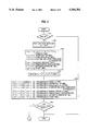
- FIG. 2 is a flow chart showing an outline of a state detection processing executed by a PMCCPU according to the embodiment
- FIG. 3 is a flow chart showing an outline of an operation time storage processing executed by the PMCCPU according to the embodiment
- FIG. 4 is a continuation of the flow chart showing the outline of the operation time storage processing
- FIG. 5 is a continuation of the flow chart showing the outline of the operation time storage processing
- FIG. 6 is a flow chart showing an outline of a display request detection processing executed by the PMCCPU according to the embodiment
- FIG. 7 is a conceptual diagram showing a file for storing daily data for one month
- FIG. 8 is a conceptual diagram showing a file for storing monthly data for one year
- FIGS. 9(a) and 9(b) show a conceptual diagram showing an example of a data display mode
- FIG. 10 is a block diagram showing an example of an operating time analyzing apparatus based on a centralized computer system.
- a motor-operated injection molding machine 19 to which an operating time analyzing apparatus according to the present invention is applied comprises a stationary platen 27, a movable platen 28, an injection cylinder 29, and a screw 30, the injection cylinder 29 including a band heater 34 for use as heating means and a thermocouple 35 for use as temperature detecting means.
- the movable platen 28 is moved along tie-bars (not shown) by means of an axial output of a servomotor M1 for mold clamping, with the aid of a drive converter 31, which is composed of a ball-nut-screw mechanism, toggle mechanism, or the like.
- the screw 30 is moved in the axial direction by means of a servomotor M3 for injection, with the aid of a drive converter 32, which is composed of a ball-nut-screw mechanism, boss-serration mechanism or the like.
- the screw 30 is rotated for metered kneading by means of a servomotor M2 with the aid of a transmission mechanism such as a gear mechanism 33.
- a numerical control device for controlling the injection molding machine 19 comprises a microprocessor (hereinafter referred to as NCCPU) 12 for numerical control and a microprocessor (hereinafter referred to as PMCCPU) 14 for a programmable machine controller.
- the PMCCPU 14 is connected, though data buses, to a ROM 17, stored with programs for controlling the sequence operation of the injection molding machine and the like, and a nonvolatile RAM 8, utilized for the storage of integrated times for individual operating conditions.
- the microprocessor 12 for numerical control is connected to a ROM 15 stored with management programs for generally controlling the injection molding machine 19, a RAM 4 used for temporary storage of data and the like, and a servo interface 11. Further, the servo interface 11 is connected to a servo circuit 1 of the servomotor M1 for mold clamping, a servo circuit 2 of the servomotor M2 for metering rotation, and a servo circuit 3 of the servomotor M3 for injection. Feedback signals from pulse coders P1, P2 and P3, which are attached to the servomotors M1 to M3 respectively are applied to the servo circuits 1, 2 and 3, respectively. In FIG. 1, only servomotors M1 to M3 are illustrated, and illustration of other servomotors, e.g., servomotors for ejector operation, mold thickness adjustment, nozzle touch, etc., is omitted.
- the NCCPU 12 and the PMCCPU 14 are connected to each other through a bus arbiter controller 13. Also, the bus arbiter controller 13 is connected to a nonvolatile common RAM 5, an input circuit 6, and an output circuit 7 through data buses.
- the servo circuit 3 having a torque limit circuit built-in, receives from the output circuit 7 a torque limit value for regulating the maximum injection pressure produced by the servomotor M3 for injection.
- the band heater 34 is on/off-controlled by the PMCCPU 14 through the the output circuit 7 and a heater circuit 10. While, the respective temperatures of individual parts of the injection cylinder 29, detected by the thermocouple 35, are A/D-converted and applied to the input circuit 6.
- the current time from a clock unit 9 is applied to the input circuit 6 of the numerical control device.
- the clock unit 9 has an auto-calendar function to automatically update the respective numbers of the year, month, and day in accordance with preset data, as well as a function of outputting the current time expressed by hour, minute, and second.
- the bus arbiter controller 13 controls the inputting and outputting of the data between the individual elements by selecting the data buses.
- An operator controller 16 constitutes an interface between numerical control device and a manual data input device with CRT display unit (hereinafter referred to as CRT/MDI) 18.
- CRT/MDI manual data input device with CRT display unit
- the CRT/MDI 18 which is composed of a control panel arranged on the injection molding machine body and terminal equipment separate from the injection molding machine body, is provided with a CRT display unit, ten-keys for data entry, soft keys for command entry, etc.
- the control panel of the CRT/MDI 18 is provided with a semiautomatic operation switch for starting execution of only one cycle of an injection stage from mold clamping to ejection in accordance with programs, an automatic operation switch for starting repeated execution of the injection stage, and a manual operation switch.
- the injection molding machine 19 has an abnormality detecting function for detecting abnormality in individual parts of the injection molding machine and outputting alarms, a counting function for cumulatively storing the-number of product shots, a cold start preventing function, etc.
- the abnormality detecting function is triggered if an abnormality is detected in the numerical control device according to self-diagnosable programs, or if an abnormality is detected in the servomotors for the individual axes.
- This function is triggered, for example, when positional deviation of the servomotors M1, M2 and M3 for mold clamping, metering rotation or injection has increased extraordinarily increase during operation due to the entry of any foreign matter in molds, nozzle clogging, solidification of resin, etc., or when movable units driven by the servomotors of the individual axes during manual operation overtravel to actuate limit switches. If such an abnormality is detected, the NCCPU 12 or PMCCPU 14 for controlling the operation concerned sets an alarm detection flag of the common RAM 5.
- a counter for cumulatively storing the number of product shots is automatically counted up every time one cycle of the injection stage by the injection molding machine 19 is completed.
- the injection molding machine 19 automatically stops in a mold open state, and the PMCCPU 14 sets a production completion flag of the common RAM 5. If the number of productions is not set, or if it is reset through the CRT/MDI 18, the value of counter and the production completion flag are reset, whereupon the automatic operation of the injection molding machine 19 will be continued until the operation is cancelled.
- the counter for cumulatively storing the number of product shots will never function unless the number of productions is set.
- a cold start prevention timer operates for a predetermined time (normally 15 to 25 minutes).
- a cold start prevention flag is set in the common RAM 5 lest the injection molding machine 19 perform the injection molding operation before the predetermined time has elapsed after having been connected to the power supply. This cold start prevention flag is automatically reset when the passage of the predetermined time is detected by means of the cold start prevention timer. When the band heater 34 is connected again to the power supply, this flag will be set again.
- the operation of the injection molding machine 19 is controlled in a manner such that the NCCPU 12, which operates in accordance with the management programs stored in the ROM 15, distributes pulses to the individual axes through the servo interface 11, and the PMCCPU 14, which operates in accordance with the sequence programs stored in the ROM 17, manages the general sequence operation, in accordance with the set values and the like stored in the common RAM 5.
- a state detection processing shown in FIG. 2, an operation time storage processing shown in FIGS. 3 to 5, and a display request detection processing shown in FIG. 8 are tasks stored in the ROM 17. Among these tasks, the task for the state detection processing of FIG. 2 is repeatedly executed at fine time intervals ⁇ t by means of the PMCCPU 14 as long as the injection molding machine 19 is connected to the power supply.
- the PMCCPU 14 determines whether or not the cold start prevention flag is set in the common RAM 5 in the state detection processing for each predetermined cycle, that is, whether or not the band heater 34 is in a heat-up stage for heating the injection cylinder 29 (Step 1). If it is detected in this step that the band heater 34 is in the heat-up stage, the execution cycle ⁇ t for the present processing is added to a heat-up time storage register Ta, and the heater heat-up time is cumulatively stored (Step S7), whereupon the state detection processing for this cycle is finished.
- Step S1 of the state detection processing of FIG. 1 is always negative (N), and Step S2 is entered. Thereupon, the PMCCPU 14 executes the state detection processing for the subsequent cycles.
- Step S2 the PMCCPU 14 determines whether or not the alarm detection flag is set, that is, whether or not an abnormality is detected in any part of the injection molding machine 19. If the abnormality is detected, the execution cycle ⁇ t is added to an alarm generation time storage register Tb, and the alarm generation time is cumulatively stored (Step S8), whereupon the state detection processing for this cycle is finished. Since the operation of the injection molding machine 19 is automatically stopped when the alarm detection flag is set, operations for any other objects of measurement will not be executed while the machine is at rest.
- Step S3 determines whether or not the production completion flag is set, that is, whether or not a predetermined number of injection molding operations are completed. If it is concluded that the predetermined number of injection molding operations are completed, the PMCCPU 14 adds the execution cycle ⁇ t to a stopping time storage register Tc for storing the stopping time after the completion of production, and cumulatively stores the stopping time after the completion of production (Step S9), whereupon the state detection processing for this cycle is finished.
- the production completion flag In order to drive the injection molding machine 19 after the completion of production, the production completion flag must be reset by operation through the CRT/MDI 18, without regard to the operation mode, manual, semiautomatic, or automatic, so that the operation time for the manual, semiautomatic, or automatic operation after the completion of production will not be added to the stopping time storage register Tc.
- any of the manual, semiautomatic, and automatic operations can selectively be executed, so that the PMCCPU 14 proceeds to a processing for discriminating the operation mode. Thereupon, the PMCCPU 14 discriminates the activated switch out of the manual operation switch, semiautomatic operation switch, and automatic operation switch arranged on the control panel on the injection molding machine body. If the manual operation is detected, the execution cycle ⁇ t is added to a manual operation time storage register Td, and the manual operation time is cumulatively stored (Steps S4 and S10). If the semiautomatic operation is detected, the execution cycle ⁇ t is added to a semiautomatic operation time storage register Te, and the semiautomatic operation time is cumulatively stored (Steps S5 and S11).
- Step S6 If the automatic operation is detected, the execution cycle ⁇ t is added to an automatic operation time storage register Tf, and the automatic operation time is cumulatively stored (Steps S6 and S12). If none of the operation switches are activated, the execution cycle ⁇ t is added to a register Tg for storing other operation times (Step S13).
- the order of discrimination processings for detecting specific operating conditions such as the heat-up stage for the heater, alarm generation, production completion, etc., which never overlap one another, can be changed as required.
- Step S14 current data on the hour, minute, and second is read from the clock unit 9, and it is determined whether or not the value of this data is identical with a predetermined data totalization time (Step S14). If the values are not identical, the operation time storage processing for this cycle is finished without executing the processing of Step S15 and subsequent processings, which will be mentioned later.
- the resolution of the clock unit 9 associated with the hour, minute, and second is matched with the execution cycle of the operation time storage processing of the PMCCPU 14, and the result of discrimination in Step S14 becomes positive (Y) only in one cycle a day.
- the PMCCPU 14 If the current data on the hour, minute, and second, in the clock unit 9, agrees with the predetermined data totalization time, the PMCCPU 14 reads current data on the date from the clock unit 9, and stores it as a date index d (Step S15).
- the PMCCPU 14 reads the value in the heat-up time storage register Ta, which is stored with the accumulated times for the specific operating states for a full day from the data totalization time of the preceding day to the current data totalization time, value in the alarm generation time storage register Tb, value in the stopping time storage register Tc, value in the manual operation time storage register Td, value in the semiautomatic operation time storage register Te, value in the automatic operation time storage register Tf, and values in the storage register Tg for storing the other operation times.
- the individual read register values (Ta to Tg) and the value of power-on time for one day, i.e., the sum of the read values, are made to respectively correspond to date index d, updated and stored in individual storage regions Tad, Tbd, Tcd, Tdd, Ted, Tfd, Tgd and T ⁇ d of a file of the nonvolatile RAM 8 for storing everyday data for one month (Step S16). Then, all the values in the individual registers Ta to Tg are initialized (Step SIT).
- the PMCCPU 14 calculates the ratio of the power-on time to a day and the respective ratios of the heater heat-up time, alarm generation time, stopping time after the completion of production, manual operation time, semiautomatic operation time, automatic operation time, and other operation times to the power-on time for one day are calculated individually, and the results of the calculation are updated and respectively stored in individual storage regions T ⁇ 'd, Ta'd, Tb'd, Tc'd, Td'd, Te'd, Tf'd and Tg'd, of the file of the nonvolatile RAM 8, corresponding to the date index d (Step S18).
- the PMCCPU 14 determines whether or not the current value d of the date read last corresponds to the totalization day or the last date of the current month (Step S19). If no correspondence is discriminated, the operation time storage processing for this cycle is finished without executing the processing of Step S20 and subsequent processings, which will be described later.
- Step S20 If the date read last corresponds to the last date of the current month, on the other hand, the PMCCPU 14 proceeds to Step S20, whereupon it reads current data on the month from the clock unit 9, and stores it as a monthly index m. Then, after initializing all the values in individual storage regions T ⁇ m, Tam, Tbm, Tcm, Tdm, Tem, Tfm and Tgm of a file of the nonvolatile RAM 8 for storing monthly data for one year (Step S21), 1 is set in a data read index i (Step S22).
- the respective integrated values of the power-on time, heater heat-up time, alarm generation time, stopping time after the completion of production, manual operation time, semiautomatic operation time, automatic operation time, and other operation times, obtained in the days from the first day to the last or d'th day of the current month, are respectively stored in the storage regions T ⁇ m, Tam, Tbm, Tcm, Tdm, Tem, Tfm and Tgm of the file (see FIG. 8) for storing data of the current month.
- the PMCCPU 14 calculates the total time (seconds) for the current month on the basis of the value of the last date d of the current month (Step S26), calculates the percentage of the power-on time in the month and the respective percentages of the heater heat-up time, alarm generation time, stopping time after the completion of production, manual operation time, semiautomatic operation time, automatic operation time, and other operation times, as compared with the power-on time for the month, and updates and respectively stores these values in individual storage regions T ⁇ 'm, Ta'm, Tb'm, Tc'm, Td'm, Te'm, Tf'm and Tg'm of the file (see FIG. 8) of the nonvolatile RAM 8, corresponding to the monthly index m (Step S27).
- the operation time storage processing for this cycle is finished.
- the operator can be informed of daily operating time data for the current month (sometimes including part of the preceding month) or monthly operating time data for the current year (sometimes including part of the preceding year) by selecting the operating time data by means of the soft keys of the CRT/MDI 18 to have these data displayed on the CRT display unit.
- the PMCCPU 14 repeatedly executes the display request detection processing with every predetermined cycle, as shown in the flow chart of FIG. 6, substantially in parallel with the state detection processing and the operation time storage processing described above.
- the PMCCPU 14 changes the display picture on the CRT display unit, when a display request from the CRT/MDI 18 is detected (Step S01), and causes the display unit of the CRT/MDI 18 to display daily operating time data for one month, as in the data display picture shown in FIG. 9(a), and monthly operating time data for one year shown in FIG. 9(b) (Step S03).
- the totalization of current day data is not completed, so that daily data for the days from the first day to the preceding day of the current month and daily data for the day of the preceding month corresponding to today and subsequent days are displayed in the display picture, which is for displaying the daily operating time data for one month, as shown in FIG. 9(a).
- the data totalization time is set for 19:00:00, and if a request is made that the operating time data be displayed at 18:30:00 on July 15, for example, daily data for the days from July 1 to July 14 and daily data for the days from June 15 to June 30 are displayed.
- the display picture for indicating the daily operating time data for one month indicates daily data for the immediately preceding one month.
- the same rule applies to the case of the monthly operating time data for one year. If the time of the request for the display of the operating time data is earlier than the predetermined data totalization time, monthly data for the months from the first month to the preceding month of the current year and monthly data for the month of the preceding year corresponding to the current and subsequent months are displayed. If the time of the request for the display of the operating time data is later than the predetermined data totalization time, on the other hand, monthly data for the months from the first month to the current month of the current year and monthly data for the month of the preceding year corresponding to the current and subsequent months are displayed, as shown in FIG. 9(b). Thus, the display picture for indicating the monthly operating time data for one year indicates monthly data for the immediately preceding year.
- the respective values of the time data displayed on the CRT shown in FIG. 9 are expressed in hour, minute and second. If the other soft keys of the CRT/MDI 18 are operated with the display picture of FIG. 9 selected, the PMCCPU 14 detects this in a discrimination processing of Step S02, and then proceeds to another selection processing depending on the operation.
- data output means is composed of the CRT display unit of the CRT/MDI 18, and the integrated times for the individual states of the injection molding machine 19 and the ratios thereof are totalized in a predetermined period for each day or month, stored in the files shown in FIGS. 7 and 8, and freely displayed at the operator's request.
- the daily or monthly data are displayed; however, the values in the individual operation time storage registers may be displayed in response to display commands without the division on the daily or monthly basis. Even in this case, the respective percentages of the operation times for the individual operating conditions, as compared with the power-on time, are calculated and displayed.
- the integrated times for the individual states and the ratios thereof may be printed out in a predetermined period for each day or month every time the processing of Step S18 or S27 in the operation time storage processing is executed.
- a file for storing the daily data for one month such as the one shown in FIG. 7, is prepared every month, it is the same as that the daily data are stored for a whole year.
- the integrated values of the various operating times for each day of the week, average operating time associated therewith, the percentage of each day of the week compared with the various operating times for each week, etc. can be calculated.
- the data are totalized by detecting the current date or month by means of the clock unit 9 which has the calendar function.
- the same processing as in this embodiment may be effected by the use of a 24-hour clock unit which can be automatically reset.
- the processings of the first embodiment can first be applied directly to the operating condition detection processing.
- the processings (FIGS. 3 to 5) of the first embodiment cannot be applied directly to the operation time storage processing. This is because, according to the first embodiment, the current date is detected from the clock unit in the processing of Step S15; the last date of the current month is detected in the processing of Step S19; and the month is read in Step S20.
- Step S19 is first removed from the operation time storage processing shown in FIG. 3, and a processing for incrementing the value of the date index d in order is executed in place of the processing of Step S15.
- the value of the date index d for the time of the first power-on operation is 0.
- the value of the date index d is updated every time the set time is detected in the discrimination processing of Step S14, thereby enabling the automatic processings of Steps S18 to S18.
- the value of the date index d needs to be initialized at the beginning of the month.
- a processing for setting the month index m and the number d of days of the month m are set by detecting a ten-key entry through the CRT/MDI 18 needs to be provided, and a processing for initializing the value of the date index d to 0 is interposed between Steps S28 and S27.
- the value of the date index d is updated in order every time the arrival of the data totalization time is detected in the discrimination processing of Step S14, so that the processings of Steps S16 to S18 are automatically executed corresponding to the updated value of the date index d. If the operator sets or inputs the old month index value m and the number d of days of the month m at the end of every month in the processing which replaces Step S20 of FIG. 4, data for the days from the first day to the last or d'th day of the m'th month are automatically added up and totalized in the processings of Steps S21 to S27.
- the value of the index d is automatically initialized to 0 in the processing between Steps S26 and S27, moreover, the value of the date index d is set again to 1 on the first day of the (m+1)'th month, whereupon the processings for one month can repeatedly be executed in like manner.
- the data are totalized daily or monthly. Alternatively, however, the data may be totalized on weekly or annual basis too.
- the individual operating conditions to be detected can optionally be selected depending on the configuration of the injection molding machine and the like. Further, the time consumed for conditioning or programming, the ratio thereof, and the like can be calculated and displayed by discriminating the mode of combination of the specific operating conditions. In order to calculate the time consumed for conditioning or programming, the ratio thereof, and the like, in some cases, external switches for exclusive use may be provided, or the key operation on the CRT/MDI 18 or the like may be detected, or otherwise state detection signals from inside the injection molding machine 19 may be used.
- the time in one day or month during which the power is off can be determined based on the value of the power-on time T ⁇ d for one day or the power-on time T ⁇ m for one month.
- an external switch or those keys of the CRT/MDI 18 corresponding to items relating to the reasons for the power cut-off can be operated so that the power-off time can be stored in the nonvolatile RAM 8 for each reason.
- the current time of the clock unit 9 can be detected in accordance with the reasons inputted through the external switch or the CRT/MDI 18 immediately before the power is cut off, and this value is stored in the nonvolatile RAM 8.
- the current time is read from the clock unit 9; the value of the current time stored when the power is cut off is subtracted from the read value; and the resulting value is stored in the nonvolatile RAM 8 corresponding to the reasons for the power cut-off.
- various items of reasons such as the periodical maintenance, absence of production plan, troubleshooting, etc. should be set and stored in advance.
- FIG. 10 is a block diagram showing the third embodiment in which a single centralized control computer 26 is provided for a plurality of injection molding machines 19a, 19b, 19c, . . .
- the principal part of the centralized control computer 26 is composed of a microprocessor 21, ROM 22, RAM 23, CRT/MDI 24, and an external memory unit 25 formed of a floppy disk or hard disk.
- These injection molding machines 19a, 19b, 19c, . . . and the centralized control computer 28 are connected though data transmission lines extending from the injection molding machines 19a, 19b, 19c, . . . and an interface 20 on the side of the centralized control computer 26.
- each of the injection molding machines 19a, 19b, 19c, . . . is substantially the same as that of the injection molding machine 19 of the foregoing first embodiment.
- a heater heat-up detection signal, alarm generation signal, production completion signal, manual operation signal, semiautomatic operation signal, automatic operation signal, etc., along with the respective codes of the individual injection molding machines, are entered in the centralized control computer 26.
- processings for each predetermined cycle such as the ones shown in FIG. 2 and FIGS. 3 to 5, are executed for the respective codes of the injection molding machines 19a, 19b, 19c, . . . on the side of the centralized control computer 26, and the external memory unit 25 is made to store the totalization results of data in its files, such as the ones shown in FIGS. 7 and 8, provided for each injection molding machine code.
- the code of a desired injection molding machine is inputted through the MDI so that only the data of the desired injection molding machine are selectively displayed.
- each of the injection molding machines 19a, 19b, 19c, . . . is of the motor-operated type in which a control device is used for internal processing, load on the respective control devices of the injection molding machine and the centralized control computer 26 can be reduced by sharing the necessary processings for the data totalizing operation between the injection molding machine and centralized control computer 26.
- each of the injection molding machines 19a, 19b, 19c, . . . may be made to execute only a state detection processing such as the one shown in FIG. 2, so that each injection molding machine is stored with data for one day, and the respective control devices of the injection molding machines 19a, 19b, 19c, . . . are polled from the centralized control computer 26 with every data totalization time, whereby the data for each injection molding machine can be collected. Every time these data are collected, the processings shown in FIGS. 3 to 5 may be executed for each injection molding machine so that the results are stored in the external memory unit 25.
- the processing of the centralized control computer 26 can be executed without regard to the connection of the injection molding machine to the power supply. Therefore, the third embodiment is one suited for the case where the reasons, time, etc. for the cut-off of the injection molding machine from the power supply should be stored. It is easy to transmit the reasons for the power cut-off from the injection molding machine to the centralized control computer 26 by means of their corresponding keys so that the centralized control computer 26 can control the reasons, time, etc. for the cut-off of each injection molding machine from the power supply, corresponding to the reasons.
- the operating conditions of the injection molding machine can be detected without interruption where detecting means for externally detecting the operating conditions of the injection molding machine without regard to the connection thereof to the power supply is provided.
- the time for the attachment or detachment of the molds or the like after the power cut-off can be controlled for each injection molding machine by means of limit switches or the like on the stationary platen 27 or movable platen 28 for detecting the attachment and detachment of the molds.
Applications Claiming Priority (3)
| Application Number | Priority Date | Filing Date | Title |
|---|---|---|---|
| JP3140582A JP2727139B2 (ja) | 1991-05-18 | 1991-05-18 | 射出成形機の稼働時間分析装置 |
| JP1-140582 | 1991-05-18 | ||
| PCT/JP1992/000623 WO1992020509A1 (en) | 1991-05-18 | 1992-05-14 | Device for analyzing working hours of injection molding machine |
Publications (1)
| Publication Number | Publication Date |
|---|---|
| US5344301A true US5344301A (en) | 1994-09-06 |
Family
ID=15272045
Family Applications (1)
| Application Number | Title | Priority Date | Filing Date |
|---|---|---|---|
| US07/961,900 Expired - Lifetime US5344301A (en) | 1991-05-18 | 1992-05-14 | Operating time analyzing apparatus for an injection molding machine |
Country Status (6)
| Country | Link |
|---|---|
| US (1) | US5344301A (ko) |
| EP (1) | EP0540752B1 (ko) |
| JP (1) | JP2727139B2 (ko) |
| KR (1) | KR0124808B1 (ko) |
| DE (1) | DE69221424T2 (ko) |
| WO (1) | WO1992020509A1 (ko) |
Cited By (15)
| Publication number | Priority date | Publication date | Assignee | Title |
|---|---|---|---|---|
| US5571539A (en) * | 1994-12-30 | 1996-11-05 | D & L Incorporated | Mold with an on-board counter or monitor |
| US5841964A (en) * | 1995-06-28 | 1998-11-24 | Canon Kabushiki Kaisha | Operating state management system |
| US5995009A (en) * | 1997-07-18 | 1999-11-30 | Sumitomo Heavy Industries, Ltd. | Warning apparatus for an injection molding machine |
| US6308141B1 (en) * | 1997-12-15 | 2001-10-23 | Fanuc Ltd. | Method of and apparatus for analyzing alarms of an injection molding machine |
| US6585919B1 (en) * | 1999-09-13 | 2003-07-01 | Kabushiki Kaisya Meiki Seisakusyo | Method and apparatus for injection molding wherein cycle time is controlled |
| US6685458B2 (en) | 2001-10-11 | 2004-02-03 | Acushnet Company | Split metal die assembly with injection cycle monitor |
| US20040093097A1 (en) * | 2002-11-07 | 2004-05-13 | Chiharu Nishizawa | Power shut-off method for injection molding machine |
| US20050194705A1 (en) * | 2004-03-03 | 2005-09-08 | Smith Roger P. | Plastic forming process monitoring and control |
| US20070186161A1 (en) * | 2005-11-17 | 2007-08-09 | Fanuc Ltd | Machine signal processing device |
| US20100168898A1 (en) * | 2008-12-30 | 2010-07-01 | Foxnum Technology Co., Ltd. | Control system and method for display of injection molding machine |
| US20100320632A1 (en) * | 2009-06-18 | 2010-12-23 | Progressive Components International Corporation | Electronic cycle counter |
| US20140134284A1 (en) * | 2012-11-09 | 2014-05-15 | Fanuc Corporation | Mold thickness adjusting apparatus of injection molding machine |
| US8883054B2 (en) | 2009-06-18 | 2014-11-11 | Progressive Components International Corporation | Mold monitoring |
| US20190294140A1 (en) * | 2016-11-16 | 2019-09-26 | Mitsubishi Electric Corporation | Work condition visualization apparatus |
| US10715464B2 (en) | 2009-06-18 | 2020-07-14 | Progressive Components International Corporation | System and method for monitoring tooling activities |
Families Citing this family (5)
| Publication number | Priority date | Publication date | Assignee | Title |
|---|---|---|---|---|
| KR100406824B1 (ko) * | 2001-08-16 | 2003-11-21 | 주식회사 대양기술 | 행정운동기계의 작동현황감지시스템 및 이의 제어 방법 |
| JP2008112209A (ja) | 2006-10-27 | 2008-05-15 | Omron Corp | 稼働状態モニタリング装置、稼働状態モニタリング方法、およびプログラム |
| JP6183708B2 (ja) * | 2013-12-17 | 2017-08-23 | 宇部興産機械株式会社 | 型締装置 |
| DE102022106288A1 (de) * | 2022-03-17 | 2023-09-21 | Kraussmaffei Technologies Gmbh | Verfahren zur Überwachung eines Maschinenteils |
| DE102022115702A1 (de) | 2022-06-23 | 2023-08-03 | Schaeffler Technologies AG & Co. KG | Verfahren zur Ermittlung von Maschinenbetriebsdaten einer Maschine, System, Computerprogramm |
Citations (11)
| Publication number | Priority date | Publication date | Assignee | Title |
|---|---|---|---|---|
| JPS57212042A (en) * | 1981-06-24 | 1982-12-27 | Toshiba Mach Co Ltd | Molding data collector for injection molding machine |
| JPS5824962A (ja) * | 1981-08-06 | 1983-02-15 | Dainippon Printing Co Ltd | 工票読取集計装置 |
| JPS58132446A (ja) * | 1982-01-29 | 1983-08-06 | リア・シ−グラ−・インコ−ポレ−テツド | 作業領域内での作業資材の流れを制御し該流れに関する実時間デ−タを集収する方法および装置 |
| EP0273981A1 (en) * | 1986-07-03 | 1988-07-13 | Fanuc Ltd. | Method of controlling an injection motor having overheat preventing function |
| JPS6490718A (en) * | 1987-09-30 | 1989-04-07 | Toyo Machinery & Metal | Molding machine provided with working state recording device |
| JPH02213904A (ja) * | 1989-02-15 | 1990-08-27 | Yokogawa Electric Corp | マルチ処理システム |
| JPH03203621A (ja) * | 1989-12-30 | 1991-09-05 | Shigumatsukusu Kk | 射出成形機監視システム |
| WO1991019601A1 (en) * | 1990-06-18 | 1991-12-26 | Fanuc Ltd | Method of monitoring operating conditions of injection molding machine |
| JPH0484305A (ja) * | 1990-07-27 | 1992-03-17 | Nec Corp | 数値制御装置の制御方式 |
| JPH04331125A (ja) * | 1991-03-12 | 1992-11-19 | Sekisui Chem Co Ltd | 射出成形品における外観不良予測方法 |
| US5200126A (en) * | 1990-11-29 | 1993-04-06 | Eastman Kodak Company | Method and apparatus for monitoring the stability of the injection molding process by measurement of screw return time |
Family Cites Families (1)
| Publication number | Priority date | Publication date | Assignee | Title |
|---|---|---|---|---|
| JP3031530U (ja) * | 1996-04-05 | 1996-11-29 | 有限会社フジ写真工芸 | カレンダーの日付色変え用シール |
-
1991
- 1991-05-18 JP JP3140582A patent/JP2727139B2/ja not_active Expired - Fee Related
-
1992
- 1992-05-14 DE DE69221424T patent/DE69221424T2/de not_active Expired - Fee Related
- 1992-05-14 KR KR1019920703323A patent/KR0124808B1/ko not_active IP Right Cessation
- 1992-05-14 WO PCT/JP1992/000623 patent/WO1992020509A1/ja active IP Right Grant
- 1992-05-14 US US07/961,900 patent/US5344301A/en not_active Expired - Lifetime
- 1992-05-14 EP EP92910206A patent/EP0540752B1/en not_active Expired - Lifetime
Patent Citations (12)
| Publication number | Priority date | Publication date | Assignee | Title |
|---|---|---|---|---|
| JPS57212042A (en) * | 1981-06-24 | 1982-12-27 | Toshiba Mach Co Ltd | Molding data collector for injection molding machine |
| JPS5824962A (ja) * | 1981-08-06 | 1983-02-15 | Dainippon Printing Co Ltd | 工票読取集計装置 |
| JPS58132446A (ja) * | 1982-01-29 | 1983-08-06 | リア・シ−グラ−・インコ−ポレ−テツド | 作業領域内での作業資材の流れを制御し該流れに関する実時間デ−タを集収する方法および装置 |
| EP0273981A1 (en) * | 1986-07-03 | 1988-07-13 | Fanuc Ltd. | Method of controlling an injection motor having overheat preventing function |
| JPS6490718A (en) * | 1987-09-30 | 1989-04-07 | Toyo Machinery & Metal | Molding machine provided with working state recording device |
| JPH02213904A (ja) * | 1989-02-15 | 1990-08-27 | Yokogawa Electric Corp | マルチ処理システム |
| JPH03203621A (ja) * | 1989-12-30 | 1991-09-05 | Shigumatsukusu Kk | 射出成形機監視システム |
| WO1991019601A1 (en) * | 1990-06-18 | 1991-12-26 | Fanuc Ltd | Method of monitoring operating conditions of injection molding machine |
| EP0487740A1 (en) * | 1990-06-18 | 1992-06-03 | Fanuc Ltd. | Method of monitoring operating conditions of injection molding machine |
| JPH0484305A (ja) * | 1990-07-27 | 1992-03-17 | Nec Corp | 数値制御装置の制御方式 |
| US5200126A (en) * | 1990-11-29 | 1993-04-06 | Eastman Kodak Company | Method and apparatus for monitoring the stability of the injection molding process by measurement of screw return time |
| JPH04331125A (ja) * | 1991-03-12 | 1992-11-19 | Sekisui Chem Co Ltd | 射出成形品における外観不良予測方法 |
Non-Patent Citations (2)
| Title |
|---|
| Y. Tsuboi, "Applications of a minicomputer in labor serving and automation", Information Processing, vol. 15, No. 4, pp. 240-245, Apr. 1974, Tokyo. |
| Y. Tsuboi, Applications of a minicomputer in labor serving and automation , Information Processing, vol. 15, No. 4, pp. 240 245, Apr. 1974, Tokyo. * |
Cited By (22)
| Publication number | Priority date | Publication date | Assignee | Title |
|---|---|---|---|---|
| US5571539A (en) * | 1994-12-30 | 1996-11-05 | D & L Incorporated | Mold with an on-board counter or monitor |
| US5841964A (en) * | 1995-06-28 | 1998-11-24 | Canon Kabushiki Kaisha | Operating state management system |
| US5995009A (en) * | 1997-07-18 | 1999-11-30 | Sumitomo Heavy Industries, Ltd. | Warning apparatus for an injection molding machine |
| CN1077494C (zh) * | 1997-07-18 | 2002-01-09 | 住友重机械工业株式会社 | 用于注射成型机的报警装置 |
| US6308141B1 (en) * | 1997-12-15 | 2001-10-23 | Fanuc Ltd. | Method of and apparatus for analyzing alarms of an injection molding machine |
| US6585919B1 (en) * | 1999-09-13 | 2003-07-01 | Kabushiki Kaisya Meiki Seisakusyo | Method and apparatus for injection molding wherein cycle time is controlled |
| US6685458B2 (en) | 2001-10-11 | 2004-02-03 | Acushnet Company | Split metal die assembly with injection cycle monitor |
| US20040093097A1 (en) * | 2002-11-07 | 2004-05-13 | Chiharu Nishizawa | Power shut-off method for injection molding machine |
| US6999823B2 (en) * | 2002-11-07 | 2006-02-14 | Nissei Plastic Industrial Co., Ltd. | Power shut-off method for injection molding machine |
| US7534378B2 (en) | 2004-03-03 | 2009-05-19 | Rexam Prescription Products Inc. | Plastic forming process monitoring and control |
| US20050194705A1 (en) * | 2004-03-03 | 2005-09-08 | Smith Roger P. | Plastic forming process monitoring and control |
| US20070186161A1 (en) * | 2005-11-17 | 2007-08-09 | Fanuc Ltd | Machine signal processing device |
| US20100168898A1 (en) * | 2008-12-30 | 2010-07-01 | Foxnum Technology Co., Ltd. | Control system and method for display of injection molding machine |
| US8116903B2 (en) * | 2008-12-30 | 2012-02-14 | Foxnum Technology Co., Ltd. | Control system and method for display of injection molding machine |
| US20100320632A1 (en) * | 2009-06-18 | 2010-12-23 | Progressive Components International Corporation | Electronic cycle counter |
| US8883054B2 (en) | 2009-06-18 | 2014-11-11 | Progressive Components International Corporation | Mold monitoring |
| US8899955B2 (en) | 2009-06-18 | 2014-12-02 | Progressive Components International Corporation | Electronic cycle counter |
| US9555570B2 (en) | 2009-06-18 | 2017-01-31 | Progressive Components International Corporation | Electronic cycle counter |
| US10715464B2 (en) | 2009-06-18 | 2020-07-14 | Progressive Components International Corporation | System and method for monitoring tooling activities |
| US20140134284A1 (en) * | 2012-11-09 | 2014-05-15 | Fanuc Corporation | Mold thickness adjusting apparatus of injection molding machine |
| US9022767B2 (en) * | 2012-11-09 | 2015-05-05 | Fanuc Corporation | Mold thickness adjusting apparatus of injection molding machine |
| US20190294140A1 (en) * | 2016-11-16 | 2019-09-26 | Mitsubishi Electric Corporation | Work condition visualization apparatus |
Also Published As
| Publication number | Publication date |
|---|---|
| KR930701283A (ko) | 1993-06-11 |
| WO1992020509A1 (en) | 1992-11-26 |
| KR0124808B1 (ko) | 1997-12-01 |
| DE69221424D1 (de) | 1997-09-11 |
| JP2727139B2 (ja) | 1998-03-11 |
| EP0540752A4 (en) | 1993-10-13 |
| DE69221424T2 (de) | 1997-12-11 |
| JPH04341817A (ja) | 1992-11-27 |
| EP0540752A1 (en) | 1993-05-12 |
| EP0540752B1 (en) | 1997-08-06 |
Similar Documents
| Publication | Publication Date | Title |
|---|---|---|
| US5344301A (en) | Operating time analyzing apparatus for an injection molding machine | |
| KR900001931B1 (ko) | 공정 모니터가 가능한 사출성형기 | |
| US6526360B1 (en) | Power consumption display device for machine | |
| US4079366A (en) | Electronic timer and thermoswitch device | |
| US5072360A (en) | Control arrangement for dental furnaces, especially microprocessor-controlled preheating furnaces | |
| EP0363498B1 (en) | Molding condition recorder for injection molding machine | |
| US6409495B1 (en) | Mold protection device for injection molding machine | |
| JPS61134218A (ja) | 熱可塑性合成樹脂射出成形システムにおけるホツトランナ−の温度制御表示装置 | |
| US5154935A (en) | Injection pressure control apparatus for an electrically-operated injection molding machine | |
| DE3725312A1 (de) | Steuergeraet fuer fluidfluss | |
| DE102006019598B4 (de) | Steuerungsvorrichtung einer Spritzgießmaschine | |
| CN101337420A (zh) | 注塑成型机的工序时间显示装置 | |
| JP2997435B2 (ja) | 射出成形機の稼働時間分析装置 | |
| EP0703516B1 (en) | Programmable electronic device for the control of irrigation systems | |
| JP4297280B2 (ja) | 射出成形用波形表示方法及び装置 | |
| JP2863030B2 (ja) | 射出成形機の作業データ登録方法及び装置 | |
| JP3193531B2 (ja) | 定期点検指示機能を有する成形機 | |
| JP3020363B2 (ja) | 成形機のモニタ条件設定方法 | |
| JP3595572B2 (ja) | 射出成形機の段取り誤り検出方法 | |
| JP2012153077A (ja) | 射出成形機の稼働状態監視装置 | |
| JP4008365B2 (ja) | 射出成形機の表示方法 | |
| JPH0320832Y2 (ko) | ||
| JPH0255117A (ja) | 射出成形機の負荷出力表示方法とその装置 | |
| JPS61130021A (ja) | プラスチツク押出成形ラインにおける生産情報管理装置 | |
| SU813484A1 (ru) | Устройство дл контрол времениРАбОТы МАшиН |
Legal Events
| Date | Code | Title | Description |
|---|---|---|---|
| AS | Assignment |
Owner name: FANUC LTD, JAPAN Free format text: ASSIGNMENT OF ASSIGNORS INTEREST.;ASSIGNORS:KAMIGUCHI, MASAO;SAITO, OSAMU;KUBOTA, KAZUO;AND OTHERS;REEL/FRAME:006532/0060 Effective date: 19921019 |
|
| STCF | Information on status: patent grant |
Free format text: PATENTED CASE |
|
| CC | Certificate of correction | ||
| FEPP | Fee payment procedure |
Free format text: PAYOR NUMBER ASSIGNED (ORIGINAL EVENT CODE: ASPN); ENTITY STATUS OF PATENT OWNER: LARGE ENTITY |
|
| FPAY | Fee payment |
Year of fee payment: 4 |
|
| FPAY | Fee payment |
Year of fee payment: 8 |
|
| FPAY | Fee payment |
Year of fee payment: 12 |