US5333845A - Damper device - Google Patents
Damper device Download PDFInfo
- Publication number
- US5333845A US5333845A US08/009,633 US963393A US5333845A US 5333845 A US5333845 A US 5333845A US 963393 A US963393 A US 963393A US 5333845 A US5333845 A US 5333845A
- Authority
- US
- United States
- Prior art keywords
- cylinder body
- piston
- string member
- damper device
- storage cabinet
- Prior art date
- Legal status (The legal status is an assumption and is not a legal conclusion. Google has not performed a legal analysis and makes no representation as to the accuracy of the status listed.)
- Expired - Lifetime
Links
- 230000002093 peripheral effect Effects 0.000 claims abstract description 20
- 230000033001 locomotion Effects 0.000 claims abstract description 15
- 230000008878 coupling Effects 0.000 claims description 19
- 238000010168 coupling process Methods 0.000 claims description 19
- 238000005859 coupling reaction Methods 0.000 claims description 19
- 238000003780 insertion Methods 0.000 claims description 8
- 230000037431 insertion Effects 0.000 claims description 8
- 239000003570 air Substances 0.000 description 34
- 230000006835 compression Effects 0.000 description 7
- 238000007906 compression Methods 0.000 description 7
- 239000012080 ambient air Substances 0.000 description 5
- 238000010276 construction Methods 0.000 description 5
- 230000009467 reduction Effects 0.000 description 5
- 230000009471 action Effects 0.000 description 3
- 239000011148 porous material Substances 0.000 description 3
- 239000011347 resin Substances 0.000 description 3
- 229920005989 resin Polymers 0.000 description 3
- 230000003247 decreasing effect Effects 0.000 description 2
- 230000002441 reversible effect Effects 0.000 description 2
- PYVHTIWHNXTVPF-UHFFFAOYSA-N F.F.F.F.C=C Chemical compound F.F.F.F.C=C PYVHTIWHNXTVPF-UHFFFAOYSA-N 0.000 description 1
- 230000003190 augmentative effect Effects 0.000 description 1
- 230000015572 biosynthetic process Effects 0.000 description 1
- 238000013016 damping Methods 0.000 description 1
- 230000003467 diminishing effect Effects 0.000 description 1
- 230000000694 effects Effects 0.000 description 1
- 238000010348 incorporation Methods 0.000 description 1
- 238000009434 installation Methods 0.000 description 1
- 230000002452 interceptive effect Effects 0.000 description 1
- 230000000644 propagated effect Effects 0.000 description 1
- 230000002829 reductive effect Effects 0.000 description 1
- 230000004044 response Effects 0.000 description 1
- 230000000717 retained effect Effects 0.000 description 1
Images


Classifications
-
- E—FIXED CONSTRUCTIONS
- E05—LOCKS; KEYS; WINDOW OR DOOR FITTINGS; SAFES
- E05F—DEVICES FOR MOVING WINGS INTO OPEN OR CLOSED POSITION; CHECKS FOR WINGS; WING FITTINGS NOT OTHERWISE PROVIDED FOR, CONCERNED WITH THE FUNCTIONING OF THE WING
- E05F3/00—Closers or openers with braking devices, e.g. checks; Construction of pneumatic or liquid braking devices
- E05F3/02—Closers or openers with braking devices, e.g. checks; Construction of pneumatic or liquid braking devices with pneumatic piston brakes
-
- F—MECHANICAL ENGINEERING; LIGHTING; HEATING; WEAPONS; BLASTING
- F16—ENGINEERING ELEMENTS AND UNITS; GENERAL MEASURES FOR PRODUCING AND MAINTAINING EFFECTIVE FUNCTIONING OF MACHINES OR INSTALLATIONS; THERMAL INSULATION IN GENERAL
- F16F—SPRINGS; SHOCK-ABSORBERS; MEANS FOR DAMPING VIBRATION
- F16F13/00—Units comprising springs of the non-fluid type as well as vibration-dampers, shock-absorbers, or fluid springs
-
- F—MECHANICAL ENGINEERING; LIGHTING; HEATING; WEAPONS; BLASTING
- F16—ENGINEERING ELEMENTS AND UNITS; GENERAL MEASURES FOR PRODUCING AND MAINTAINING EFFECTIVE FUNCTIONING OF MACHINES OR INSTALLATIONS; THERMAL INSULATION IN GENERAL
- F16F—SPRINGS; SHOCK-ABSORBERS; MEANS FOR DAMPING VIBRATION
- F16F9/00—Springs, vibration-dampers, shock-absorbers, or similarly-constructed movement-dampers using a fluid or the equivalent as damping medium
- F16F9/02—Springs, vibration-dampers, shock-absorbers, or similarly-constructed movement-dampers using a fluid or the equivalent as damping medium using gas only or vacuum
- F16F9/0209—Telescopic
- F16F9/0218—Mono-tubular units
-
- E—FIXED CONSTRUCTIONS
- E05—LOCKS; KEYS; WINDOW OR DOOR FITTINGS; SAFES
- E05Y—INDEXING SCHEME ASSOCIATED WITH SUBCLASSES E05D AND E05F, RELATING TO CONSTRUCTION ELEMENTS, ELECTRIC CONTROL, POWER SUPPLY, POWER SIGNAL OR TRANSMISSION, USER INTERFACES, MOUNTING OR COUPLING, DETAILS, ACCESSORIES, AUXILIARY OPERATIONS NOT OTHERWISE PROVIDED FOR, APPLICATION THEREOF
- E05Y2900/00—Application of doors, windows, wings or fittings thereof
- E05Y2900/50—Application of doors, windows, wings or fittings thereof for vehicles
- E05Y2900/53—Type of wing
- E05Y2900/538—Interior lids
Definitions
- This invention relates to a damper device used in a storage cabinet such as a glove compartment furnished for the dashboard of an automobile.
- a storage cabinet such as a glove compartment is, at times, required to be furnished with a damper device for controlling the opening and shutting motions of the storage cabinet for the purpose of preventing the storage cabinet from suddenly opening itself or emitting the unpleasant noise of an impact.
- damper devices are constructed of a piston that has an O-ring provided on the circumferential edge thereof and is slidably disposed inside a cylinder body.
- a compression coil spring serves to urge the piston in one fixed direction.
- a long piston rod integrally extends from the piston and protrudes outwardly from the cylinder body.
- a string member has one terminal part thereof connected to the leading terminal part of the piston rod and the other terminal end of a string member fastened either to the peripheral member of the storage cabinet, when the cylinder body is fixed to the storage cabinet, or to the storage cabinet when the cylinder body is fixed to the peripheral member of the storage cabinet.
- the conventional damper devices therefore require not only a guide means such as a roller for guiding the string member in the direction of disposition of the string member, but also such fixing parts as bolts and nuts for fixing the guide means at pertinent fixed positions.
- a guide means such as a roller for guiding the string member in the direction of disposition of the string member
- fixing parts as bolts and nuts for fixing the guide means at pertinent fixed positions.
- the natural consequence is that the number of component parts is proportionately increased, and the damper devices suffer from additional size and increased of cost.
- the number of steps of work involved is augmented, and the operational efficiency of the assembly is jeopardized, possibly to the extent of posing a problem.
- One object of this invention is to provide an air cylinder type damper device which allows a perfect solution of the problems suffered by the conventional damper devices as described above.
- an air cylinder type damper device for a storage cabinet that comprises a cylinder body having a front terminal opening, a piston slidably disposed inside the cylinder body, a spring member disposed inside the cylinder body for biasing the piston in a shutting direction of the storage cabinet, a string member having one terminal part thereof connected to the piston within the cylinder body, and a cap provided on the front terminal opening of the cylinder body and possessed of a curved peripheral guide face capable of guiding the string member in the direction of disposition thereof.
- An opening motion of the storage cabinet is controlled by moving the piston in one direction through the string member against the biasing force of the spring member, and a shutting motion of the storage cabinet is controlled by moving the piston in the opposite direction through the string member owing to the biasing force of the spring member.
- FIG. 1 is a cross section illustrating a first embodiment of the damper device according to this invention.
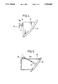
- FIG. 2 is an explanatory view illustrating a first example of the state of attachment of the damper device.
- FIG. 3 is an explanatory view illustrating a second example of the state of attachment of the damper device.
- FIG. 4 is an explanatory view illustrating a third example of the state of attachment of the damper device.
- FIG. 5 is an explanatory view illustrating a fourth example of the state of attachment of the damper device.
- FIG. 6 is a cross section illustrating an essential part of the damper device to aid in the explanation of the flow of air into the damper device.
- FIG. 7 is a cross section illustrating the essential part of the damper device to aid in the explanation of the flow of air out of the damper device.
- FIG. 8 is an explanatory cross section illustrating the essential part of the damper device in a state of equalized pressure.
- FIG. 9 is a cross section illustrating a second embodiment of the damper device according to this invention.
- FIG. 10 is a partially cutaway perspective view illustrating a piston of the damper device of FIG. 9.
- FIG. 11 is a perspective view illustrating a coupling device for the damper device of FIG. 9.
- FIG. 12 is a perspective view of an essential part of the damper device of FIG. 9 and illustrating a first example of the part provided with a cylinder body of the damper device.
- FIG. 13 is an explanatory view illustrating a second example of the part provided with the cylinder body.
- FIG. 14 is an explanatory view illustrating a third example of the part provided with the cylinder body.
- FIG. 15 is an explanatory view illustrating a fourth example of the part provided with the cylinder body.
- this damper device has a precondition that a piston 2 having an O-ring 3 set on a circumferential edge thereof be slidably disposed inside a cylinder body 1, and that a compression coil spring 4 be adapted to urge the piston 2 in one direction.
- the damper device is characterized by adopting a construction permitting one terminal part Sa of a string member S to be directly connected to the piston 2 inside the cylinder body 1, unlike the conventional damper device which has a long piston rod extending from the piston and connecting one terminal part of the string member to the piston.
- the piston 2 is integrally provided with a hook part 5 for hooking the one terminal part Sa of the string member S.
- the cylinder body 1 has a front terminal opening part sheathed with a cap 6 made of resin and possessed of a curved peripheral guide face 6a capable of guiding the string member S connected to the hook part 5 in the direction of disposition of the string member S as illustrated in FIG. 1.
- the curved peripheral guide face 6a as can be seen from FIG. 1, for example, thus curves from a portion thereof having an annular surface that faces radially inwardly and extends substantially axially with respect to the cylinder body 1 to a portion thereof that has an annular surface that faces substantially axially and extends substantially radially with respect to the cylinder body 1.
- the peripheral guide face 6a curves from a position capable of guiding the string member S axially coming out of the cylinder body 1, to a position where the string member S has turned 90 degrees, as illustrated in FIG. 1.
- the curved peripheral guide face 6a further curves to a portion thereof that has an annular surface that faces radially outwardly and extends substantially axially with respect to the cylinder body 1.
- the string member S can therefore freely protrude in a desired direction from within the cylinder body 1 by the guiding action of the peripheral guide face 6a of the cap 6 without requiring the use of a guide means, such as a roller, found in the conventional device.
- a guide means such as a roller
- the omission of the piston rod allows the entirety of the device, inclusive of the cylinder body 1, to be miniaturized.
- a seating valve 8 containing an orifice 8a, a backup spring 9 and an air filter 10 are sequentially disposed in the order mentioned inside the cylindrical part 7a.
- a retainer 11 provided with an opening 11a is set in place so as to fix the air filter 10.
- the seating valve 8 is attached fast to the surface of the rear wall 7 and the air filter 10 is pressed against the surface of the retainer 11 by virtue of the spring pressure of the backup spring 9.
- This air filter 10 is desirably formed of a porous resin such as porous ethylene tetrafluoride resin so that the air filter 10 can produce a prescribed amount of resistance and simultaneously allow the flow of air and permit a fine adjustment of the flow volume of the air and, at the same time, manifest the function of absorbing noise owing to the action of the numerous minute pores.
- the damper device constructed as described above therefore, is installed in its working position simply by utilizing a fitting part 1a formed on the cylinder body 1 for fixing the cylinder body 1 at a stated position by means of screws, for example.
- the fixation of the cylinder body 1 is attained at an optimum site, freely selected due to the direction of disposition of the string member S and the miniaturization allowed for the cylinder body 1.
- this fixation is attained, as shown in FIG. 2, for example, by fixing the cylinder body 1 on the side of a dashboard P opposed to the rear face of a glove compartment B, and attaching the other terminal part Sb of the string member S fast to the a glove compartment lid R either directly or through a connecting member 12.
- the fixation can be achieved as illustrated in FIG. 3 and FIG. 4, by fixing the cylinder body 1 on the lateral side or rear side of the glove compartment B and attaching the other terminal part Sb of the string member S on the corresponding side of the dashboard P, or, where the damper device is of the type adapted to be opened solely on the glove compartment lid R side, as shown in FIG.
- the glove compartment B When actual use, the glove compartment B is rotated under its own weight in the opening direction by releasing a lock means (not shown).
- the string member S is drawn outwardly, guided by the peripheral guide face 6a of the cap 6, and in response thereto, the piston 2 is moved toward the cap 6 in spite of the spring pressure of the compression coil spring 4 and the glove compartment B is allowed to rotate.
- the motion of the piston 2 causes the air, while being passed through the minute pores in the air filter 10 and aspirated into the cylinder body 1 via the orifice 8a of the seating valve 8 as illustrated in FIG. 6, to brake the motion of the piston 2.
- the air controls opening motion of the glove compartment B and infallibly makes the glove compartment B rotate gradually in the opening direction.
- the glove compartment B is shut simply by causing it to be rotated in the reverse direction. During this rotation, the urging spring pressure of the compression coil spring 4 compels the piston 2 to move in the direction opposite to the opening direction mentioned above and, at the same time, causes the string member S to be retracted into the cylinder body 1, guided by the peripheral guide face 6a of the cap 6.
- the air filter 10 When the air flows into the cylindrical part 7a, the air filter 10 therein prevents this air from being discharged instantaneously into the ambient air, and ensures fine adjustment of the flow volume of air and gradual release thereof into the ambient air. As a result, the seating valve 8 is slowly returned and is precluded from emitting noise in its collision against the rear wall 7. Even if the collision happens to emit noise, this noise is prevented from being propagated into the ambient air due to the sound-abating action of the air filter 10.
- FIG. 9 An air cylinder type damper device according to a second embodiment of this invention will be described below with reference to FIG. 9 to FIG. 12.
- the second embodiment contemplates integrally forming a glove compartment B and a cylinder body 1 as shown in FIG. 9 and incorporating in the integrally formed cylinder body 1 a piston 2 having one terminal part Sa of a string member S connected thereto through a coupling piece 14.
- the second embodiment unlike the first embodiment, renders completely unnecessary the work of fixing the cylinder body 1 on the glove compartment B and therefore ensures a generous simplification of the assembly work and, as a result, promises fewer costs and saves installation space.
- the second embodiment is identical with the first embodiment in that the cap 6 provided with the peripheral guide face 6a is fitted on the front opening part side of the cylinder body 1. It is different from the first embodiment in that, first of all, the one terminal part Sa of the string member S is connected to the piston 2 through the coupling piece 14, adapted to retain a calked piece 13 provided on the one terminal part Sa of the string member S.
- the piston 2 is formed as a hollow article.
- an insertion mouth part 15 for allowing insertion therein of the coupling piece 14 and a pair of opposed slits 16 are formed on the front terminal part side of the piston 2, and an orifice 17 is bored on the rear terminal part side thereof.
- the coupling piece 14 is formed as a cylindrical article whose outside diameter fits through the insertion mouth part 15 of the piston 2 and a flange part 18.
- a pair of fastening shoulders 19 are formed integrally on the outer circumferential part of the coupling piece 14.
- a cylindrical part 7a provided as the rear wall 7 of the cylinder body 1, has a simple construction. Disposed therein is a seating valve 8 containing no orifice held by a flexible retainer 11. Owing to this construction, the incorporation of the cylindrical part 7a in the integrally formed cylinder body 1 is facilitated.
- the damper device can be put to normal use, for example, by integrally forming as one piece the cylinder body 1 in a lateral state or a longitudinal state on the lateral surface of the glove compartment B, incorporating in this cylinder body 1 the piston 2 having one terminal part Sa of the string member S connected thereto through the coupling piece 14 and the compression coil spring 4, and causing the other terminal part Sb of the string member S to be extended over the guide face 6a the cap 6 and attached fast to the dashboard P, as illustrated in FIG. 12.
- the site and the directionality for the formation of the cylinder body 1 are not limited to those of the particular construction described above.
- the optimum site can be freely and ideally selected on the rear side of the glove compartment B, on the bottom part side of the glove compartment B, or on the inner side of the lateral surface of the glove compartment B, as respectively illustrated in FIG. 13 to FIG. 15, depending on the shape of the glove compartment B or the positional relation of the cylinder body 1 with the dashboard P. If, in this case, the string member S is desired to be guided in a specific direction of disposition, the necessity for incorporating the independent guide means and the attendant fixing parts as found in the conventional damping device, can be obviated by having such guide means additionally formed integrally with the glove compartment B.
- the cylinder body 1 is allowed to enjoy a reduction in size because the string member S is connected to the piston 2.
- the damp a device as a whole can be expected to enjoy a reduction in size because the cylinder body 1 is integrally formed with the glove compartment B.
- the string member S is drawn outwardly, guided on the peripheral guide face 6a of the cap 6, and the piston 2 is consequently moved toward the cap 6 side in spite of the urging spring pressure of the compression coil spring 4.
- Air which then exists inside the cylinder body 1 is forced to flow through the interior of the coupling piece 14 and is aspirated through the orifice 17 of the piston 2 into the rear terminal part side of the cylinder proper 1.
- the piston 2 is placed under a braking force and the opening motion of the glove compartment B is controlled.
- the urging spring pressure of the compression coil spring 4 moves the piston 2 in the reverse direction and consequently compresses the air existing on the rear terminal part side of the interior of the cylinder body 1 and forces the air to flow through the air vent in the rear wall 7 and reach the seating valve 8.
- the flexible retainer 11 is deformed and the seating valve 8 is moved away from the rear wall 7, and the air under discussion is discharged into the ambient air through an air vent 20 formed in the lateral part of the cylindrical part 7a.
- the shutting motion of the glove compartment B is controlled as expected.
- this invention obviates the necessity for using an independent guide means for fixing the direction of disposition of the string member and the attendant parts and, therefore, permits a generous reduction in the number of component parts of the device and the number of steps of work assembly and enables the device to be effectively reduced in size and cost.
- the entirety of the device enjoys a further reduction in size and the operation and effect of this invention described above is promoted and the work of assembly of the device is decisively simplified. Even from this point of view, the cost of the device can be expected to be appreciably decreased.
Landscapes
- Engineering & Computer Science (AREA)
- General Engineering & Computer Science (AREA)
- Mechanical Engineering (AREA)
- Vehicle Step Arrangements And Article Storage (AREA)
- Fluid-Damping Devices (AREA)
Applications Claiming Priority (2)
| Application Number | Priority Date | Filing Date | Title |
|---|---|---|---|
| JP1992025040U JP2557064Y2 (ja) | 1992-03-25 | 1992-03-25 | 収納箱等のダンパ−装置の構造 |
| JP4-025040[U] | 1992-03-25 |
Publications (1)
| Publication Number | Publication Date |
|---|---|
| US5333845A true US5333845A (en) | 1994-08-02 |
Family
ID=12154802
Family Applications (1)
| Application Number | Title | Priority Date | Filing Date |
|---|---|---|---|
| US08/009,633 Expired - Lifetime US5333845A (en) | 1992-03-25 | 1993-01-27 | Damper device |
Country Status (4)
| Country | Link |
|---|---|
| US (1) | US5333845A (de) |
| EP (1) | EP0562284B1 (de) |
| JP (1) | JP2557064Y2 (de) |
| DE (1) | DE69302512T2 (de) |
Cited By (22)
| Publication number | Priority date | Publication date | Assignee | Title |
|---|---|---|---|---|
| US5845749A (en) * | 1995-10-11 | 1998-12-08 | Tmj Properties, L.L.C. | Linear motion absorber with synthetic components |
| US5906173A (en) * | 1998-06-10 | 1999-05-25 | Day, Jr.; Charlie E | Anchor line shock absorber |
| EP0987465A2 (de) | 1998-09-14 | 2000-03-22 | Illinois Tool Works Inc. | Regulierbarer Dämpfer |
| US6220583B1 (en) * | 1998-11-06 | 2001-04-24 | Piolax, Inc. | Air damper with hook on piston |
| US6269919B1 (en) * | 1998-09-14 | 2001-08-07 | Illinois Tool Works Inc. | Plastic strand damper |
| US6345583B1 (en) | 2000-07-11 | 2002-02-12 | Willie L. Thackston | Bi-directional dampening device and method therefor |
| US6367785B1 (en) * | 1999-10-08 | 2002-04-09 | Piolax, Inc. | Air damper |
| US6422542B2 (en) * | 2000-01-11 | 2002-07-23 | Itw Automotive Products Gmbh & Co. Kg | Air damper for movable elements, in particular in automobiles |
| US6578833B2 (en) * | 1999-12-10 | 2003-06-17 | Piolax, Inc. | String pull-in device |
| US20040055109A1 (en) * | 2002-09-20 | 2004-03-25 | Piolax Inc. | String type air damper |
| US20040159410A1 (en) * | 2003-02-14 | 2004-08-19 | Hunter Douglas Industries Bv | Cord tensioner |
| US20050093213A1 (en) * | 2003-10-31 | 2005-05-05 | Hyundai Motor Company | Air damper of vehicle glove compartment |
| DE10356385A1 (de) * | 2003-12-03 | 2005-06-30 | Fischer Automotive Systems Gmbh | Antriebsvorrichtung, insbesondere für einen Deckel eines Ablagefachs für Kraftfahrzeuge |
| US20070108676A1 (en) * | 2005-11-14 | 2007-05-17 | Zeilenga Chad K | Viscous strand damper assembly |
| US20070187195A1 (en) * | 2006-02-16 | 2007-08-16 | Woo Chul Park | Glove box lamp switch |
| CN103438138A (zh) * | 2013-08-15 | 2013-12-11 | 苏新文 | 内部小孔进气拉线式空气阻尼器 |
| CN103507721A (zh) * | 2013-10-29 | 2014-01-15 | 长城汽车股份有限公司 | 车辆杂物盒 |
| CN103557259A (zh) * | 2013-11-14 | 2014-02-05 | 苏新文 | 动滑轮拉绳式空气阻尼器 |
| US9475421B2 (en) | 2013-10-23 | 2016-10-25 | Burton Technologies, Llc | Reflector damper bracket |
| US20170284141A1 (en) * | 2016-03-30 | 2017-10-05 | Ford Global Technologies, Llc | Bellows spring damper |
| US9931747B1 (en) * | 2015-11-12 | 2018-04-03 | Power Tork Hydraulics, Inc. | Tool handling system |
| US11719381B2 (en) | 2020-10-05 | 2023-08-08 | Asyst Technologies L.L.C. | Adjustable linkage arm |
Families Citing this family (21)
| Publication number | Priority date | Publication date | Assignee | Title |
|---|---|---|---|---|
| DE29600438U1 (de) * | 1996-01-12 | 1996-04-04 | Paulmann & Crone GmbH & Co KG, 58509 Lüdenscheid | Vorrichtung zur Verlangsamung der Bewegung einer aufschwenkbaren Klappe |
| DE29610915U1 (de) * | 1996-06-21 | 1996-08-29 | Hörauf & Kohler KG, 86199 Augsburg | Pneumatischer Bewegungsdämpfer |
| US6062352A (en) * | 1998-08-24 | 2000-05-16 | Piolax, Inc. | Air damper |
| JP4624507B2 (ja) * | 1999-06-16 | 2011-02-02 | 株式会社ニフコ | ダンパー |
| JP3513650B2 (ja) * | 2000-01-07 | 2004-03-31 | 株式会社パイオラックス | エアダンパー |
| JP3768061B2 (ja) | 2000-03-17 | 2006-04-19 | 株式会社パイオラックス | エアダンパー |
| SG86388A1 (en) * | 2000-04-06 | 2002-02-19 | Huang Hwa Shan | Automatic door closing device |
| JP2002039249A (ja) * | 2000-07-25 | 2002-02-06 | Masaaki Inoue | 車両用エアーオイルダンパーサスペンション |
| JP2002104082A (ja) * | 2000-09-28 | 2002-04-09 | Piolax Inc | ボックス体の開閉装置 |
| US7152718B2 (en) | 2002-04-16 | 2006-12-26 | Illinois Tool Works Inc | Damper |
| JP2004175151A (ja) * | 2002-11-25 | 2004-06-24 | Nifco Inc | ダンパユニット及びこのダンパユニットを用いたクローブボックス装置 |
| JP4240478B2 (ja) * | 2004-03-31 | 2009-03-18 | 株式会社パイオラックス | 車両用収納装置 |
| DK1662170T3 (da) * | 2004-11-26 | 2008-10-13 | Christian Krischke-Lengersdorf | Pneumatisk dæmper |
| JP4572773B2 (ja) * | 2005-08-10 | 2010-11-04 | トヨタ自動車株式会社 | 車両のサスペンション装置 |
| DE102005043785A1 (de) * | 2005-09-14 | 2007-03-22 | Hörauf & Kohler Verwaltungs KG | Bewegungsdämpfer |
| KR101024096B1 (ko) * | 2008-08-05 | 2011-03-22 | 덕양산업주식회사 | 암레스트 |
| JP5133198B2 (ja) * | 2008-10-23 | 2013-01-30 | 株式会社ニフコ | ダンパー装置 |
| DE102009001178B4 (de) * | 2009-02-26 | 2013-03-14 | Faurecia Innenraum Systeme Gmbh | Staufach |
| JP2011069424A (ja) * | 2009-09-25 | 2011-04-07 | Nifco Inc | ダンパー装置 |
| CN104895434B (zh) * | 2015-06-09 | 2017-02-15 | 上海琦天汽车科技有限公司 | 拉绳式空气阻尼器 |
| WO2018133086A1 (zh) * | 2017-01-23 | 2018-07-26 | 清展科技股份有限公司 | 一种滚动条式屏幕及其屏幕定位装置 |
Citations (9)
| Publication number | Priority date | Publication date | Assignee | Title |
|---|---|---|---|---|
| US2420276A (en) * | 1945-04-02 | 1947-05-06 | Gen Spring Corp | Support |
| US2841813A (en) * | 1954-11-16 | 1958-07-08 | Wright Products Inc | Door check |
| US3072954A (en) * | 1960-09-07 | 1963-01-15 | Independent Lock Co | Door closer construction |
| FR2603062A1 (fr) * | 1986-08-22 | 1988-02-26 | Daimler Benz Ag | Dispositif de freinage du mouvement d'ouverture de volets et de couvercles |
| JPS63196752A (ja) * | 1987-02-09 | 1988-08-15 | 三井化学株式会社 | フエルト複合成形体 |
| EP0348296A1 (de) * | 1988-06-20 | 1989-12-27 | Automobiles Peugeot | Handschuhkasten oder ein anderer Behälter mit einem schwenkbaren Deckel |
| US4920609A (en) * | 1989-07-24 | 1990-05-01 | Solid Well International Corp. | Pneumatic door closer |
| JPH02147350A (ja) * | 1988-11-30 | 1990-06-06 | Tdk Corp | サーマルヘッド |
| US4955309A (en) * | 1989-05-08 | 1990-09-11 | International Nautical Supplies, Inc. | Yieldable line assembly and in line shock absorber |
Family Cites Families (2)
| Publication number | Priority date | Publication date | Assignee | Title |
|---|---|---|---|---|
| JPH0539005Y2 (de) * | 1987-06-09 | 1993-10-01 | ||
| JPH0752762Y2 (ja) * | 1989-05-17 | 1995-12-06 | 日産自動車株式会社 | バケット型収納箱の開閉制御装置 |
-
1992
- 1992-03-25 JP JP1992025040U patent/JP2557064Y2/ja not_active Expired - Lifetime
-
1993
- 1993-01-27 US US08/009,633 patent/US5333845A/en not_active Expired - Lifetime
- 1993-02-19 EP EP93102659A patent/EP0562284B1/de not_active Expired - Lifetime
- 1993-02-19 DE DE69302512T patent/DE69302512T2/de not_active Expired - Lifetime
Patent Citations (9)
| Publication number | Priority date | Publication date | Assignee | Title |
|---|---|---|---|---|
| US2420276A (en) * | 1945-04-02 | 1947-05-06 | Gen Spring Corp | Support |
| US2841813A (en) * | 1954-11-16 | 1958-07-08 | Wright Products Inc | Door check |
| US3072954A (en) * | 1960-09-07 | 1963-01-15 | Independent Lock Co | Door closer construction |
| FR2603062A1 (fr) * | 1986-08-22 | 1988-02-26 | Daimler Benz Ag | Dispositif de freinage du mouvement d'ouverture de volets et de couvercles |
| JPS63196752A (ja) * | 1987-02-09 | 1988-08-15 | 三井化学株式会社 | フエルト複合成形体 |
| EP0348296A1 (de) * | 1988-06-20 | 1989-12-27 | Automobiles Peugeot | Handschuhkasten oder ein anderer Behälter mit einem schwenkbaren Deckel |
| JPH02147350A (ja) * | 1988-11-30 | 1990-06-06 | Tdk Corp | サーマルヘッド |
| US4955309A (en) * | 1989-05-08 | 1990-09-11 | International Nautical Supplies, Inc. | Yieldable line assembly and in line shock absorber |
| US4920609A (en) * | 1989-07-24 | 1990-05-01 | Solid Well International Corp. | Pneumatic door closer |
Cited By (28)
| Publication number | Priority date | Publication date | Assignee | Title |
|---|---|---|---|---|
| US5845749A (en) * | 1995-10-11 | 1998-12-08 | Tmj Properties, L.L.C. | Linear motion absorber with synthetic components |
| US5906173A (en) * | 1998-06-10 | 1999-05-25 | Day, Jr.; Charlie E | Anchor line shock absorber |
| EP0987465A2 (de) | 1998-09-14 | 2000-03-22 | Illinois Tool Works Inc. | Regulierbarer Dämpfer |
| US6189662B1 (en) | 1998-09-14 | 2001-02-20 | Illinois Tool Works Inc. | Adjustable damper |
| US6269919B1 (en) * | 1998-09-14 | 2001-08-07 | Illinois Tool Works Inc. | Plastic strand damper |
| EP0987465A3 (de) * | 1998-09-14 | 2002-09-11 | Illinois Tool Works Inc. | Regulierbarer Dämpfer |
| US6220583B1 (en) * | 1998-11-06 | 2001-04-24 | Piolax, Inc. | Air damper with hook on piston |
| DE10025297B4 (de) * | 1999-06-08 | 2006-05-18 | Illinois Tool Works Inc., Glenview | Dämpfer |
| US6367785B1 (en) * | 1999-10-08 | 2002-04-09 | Piolax, Inc. | Air damper |
| US6578833B2 (en) * | 1999-12-10 | 2003-06-17 | Piolax, Inc. | String pull-in device |
| US6422542B2 (en) * | 2000-01-11 | 2002-07-23 | Itw Automotive Products Gmbh & Co. Kg | Air damper for movable elements, in particular in automobiles |
| US6345583B1 (en) | 2000-07-11 | 2002-02-12 | Willie L. Thackston | Bi-directional dampening device and method therefor |
| US20040055109A1 (en) * | 2002-09-20 | 2004-03-25 | Piolax Inc. | String type air damper |
| US7367086B2 (en) * | 2002-09-20 | 2008-05-06 | Piolax Inc. | String type air damper |
| US20040159410A1 (en) * | 2003-02-14 | 2004-08-19 | Hunter Douglas Industries Bv | Cord tensioner |
| US7108038B2 (en) * | 2003-02-14 | 2006-09-19 | Hunter Douglas Industries Bv | Cord tensioner |
| US20050093213A1 (en) * | 2003-10-31 | 2005-05-05 | Hyundai Motor Company | Air damper of vehicle glove compartment |
| DE10356385A1 (de) * | 2003-12-03 | 2005-06-30 | Fischer Automotive Systems Gmbh | Antriebsvorrichtung, insbesondere für einen Deckel eines Ablagefachs für Kraftfahrzeuge |
| US20070108676A1 (en) * | 2005-11-14 | 2007-05-17 | Zeilenga Chad K | Viscous strand damper assembly |
| US20070187195A1 (en) * | 2006-02-16 | 2007-08-16 | Woo Chul Park | Glove box lamp switch |
| CN103438138A (zh) * | 2013-08-15 | 2013-12-11 | 苏新文 | 内部小孔进气拉线式空气阻尼器 |
| US9475421B2 (en) | 2013-10-23 | 2016-10-25 | Burton Technologies, Llc | Reflector damper bracket |
| CN103507721A (zh) * | 2013-10-29 | 2014-01-15 | 长城汽车股份有限公司 | 车辆杂物盒 |
| CN103557259A (zh) * | 2013-11-14 | 2014-02-05 | 苏新文 | 动滑轮拉绳式空气阻尼器 |
| US9931747B1 (en) * | 2015-11-12 | 2018-04-03 | Power Tork Hydraulics, Inc. | Tool handling system |
| US20170284141A1 (en) * | 2016-03-30 | 2017-10-05 | Ford Global Technologies, Llc | Bellows spring damper |
| US10066431B2 (en) * | 2016-03-30 | 2018-09-04 | Ford Global Technologies Llc | Bellows spring damper |
| US11719381B2 (en) | 2020-10-05 | 2023-08-08 | Asyst Technologies L.L.C. | Adjustable linkage arm |
Also Published As
| Publication number | Publication date |
|---|---|
| JPH0576894U (ja) | 1993-10-19 |
| DE69302512D1 (de) | 1996-06-13 |
| JP2557064Y2 (ja) | 1997-12-08 |
| EP0562284B1 (de) | 1996-05-08 |
| DE69302512T2 (de) | 1996-10-31 |
| EP0562284A1 (de) | 1993-09-29 |
Similar Documents
| Publication | Publication Date | Title |
|---|---|---|
| US5333845A (en) | Damper device | |
| US5647578A (en) | Latch mechanism | |
| US4110868A (en) | Air damper | |
| JP3513650B2 (ja) | エアダンパー | |
| US4295412A (en) | Hose with a one-way valve for a vacuum operated servomotor | |
| US6220583B1 (en) | Air damper with hook on piston | |
| HU220546B1 (hu) | Állítószerkezet porszívó teleszkópos szívócsövéhez | |
| US20060072965A1 (en) | Coupling device for a damper | |
| US6367785B1 (en) | Air damper | |
| US5649691A (en) | Shock absorber and pneumatic spring assembly | |
| JP3728246B2 (ja) | 紐の引き込み装置 | |
| JP4636987B2 (ja) | エアダンパ | |
| JP3463270B2 (ja) | 収納箱のダンパー装置 | |
| JPH056045B2 (de) | ||
| CN112384672A (zh) | 车门定位保持器 | |
| JP2594630Y2 (ja) | グロ−ブボックスリッドのダンパ−の構造 | |
| JP3790300B2 (ja) | 収納箱のダンパー装置 | |
| CN212041069U (zh) | 洗车水枪 | |
| JP3913429B2 (ja) | エアダンパー | |
| JP2594638Y2 (ja) | 収納箱のダンパー装置の構造 | |
| CN114593260A (zh) | 一种电磁阀装置 | |
| CN115704481A (zh) | 节流装置及制冷设备 | |
| CN114593261A (zh) | 一种电磁阀装置 | |
| KR100381222B1 (ko) | 자동차용 후드 잠금 장치 | |
| KR20240063703A (ko) | 이동식 가구부속품용의 충격흡수장치 |
Legal Events
| Date | Code | Title | Description |
|---|---|---|---|
| AS | Assignment |
Owner name: KATO HATSUJO KAISHA, LTD., JAPAN Free format text: ASSIGNMENT OF ASSIGNORS INTEREST.;ASSIGNOR:SATO, SEIICHI;REEL/FRAME:006429/0031 Effective date: 19930114 |
|
| STCF | Information on status: patent grant |
Free format text: PATENTED CASE |
|
| FEPP | Fee payment procedure |
Free format text: PAYOR NUMBER ASSIGNED (ORIGINAL EVENT CODE: ASPN); ENTITY STATUS OF PATENT OWNER: LARGE ENTITY |
|
| FPAY | Fee payment |
Year of fee payment: 4 |
|
| FPAY | Fee payment |
Year of fee payment: 8 |
|
| FPAY | Fee payment |
Year of fee payment: 12 |