US5120928A - Installation for the laser marking of the surface of a cheese or delicatessen food product - Google Patents
Installation for the laser marking of the surface of a cheese or delicatessen food product Download PDFInfo
- Publication number
- US5120928A US5120928A US07/586,946 US58694690A US5120928A US 5120928 A US5120928 A US 5120928A US 58694690 A US58694690 A US 58694690A US 5120928 A US5120928 A US 5120928A
- Authority
- US
- United States
- Prior art keywords
- axis
- installation
- supporting tray
- laser beam
- carriage
- Prior art date
- Legal status (The legal status is an assumption and is not a legal conclusion. Google has not performed a legal analysis and makes no representation as to the accuracy of the status listed.)
- Expired - Lifetime
Links
Images


Classifications
-
- B—PERFORMING OPERATIONS; TRANSPORTING
- B41—PRINTING; LINING MACHINES; TYPEWRITERS; STAMPS
- B41M—PRINTING, DUPLICATING, MARKING, OR COPYING PROCESSES; COLOUR PRINTING
- B41M5/00—Duplicating or marking methods; Sheet materials for use therein
- B41M5/26—Thermography ; Marking by high energetic means, e.g. laser otherwise than by burning, and characterised by the material used
-
- A—HUMAN NECESSITIES
- A01—AGRICULTURE; FORESTRY; ANIMAL HUSBANDRY; HUNTING; TRAPPING; FISHING
- A01J—MANUFACTURE OF DAIRY PRODUCTS
- A01J27/00—After-treatment of cheese; Coating the cheese
- A01J27/005—Marking cheese
-
- A—HUMAN NECESSITIES
- A22—BUTCHERING; MEAT TREATMENT; PROCESSING POULTRY OR FISH
- A22C—PROCESSING MEAT, POULTRY, OR FISH
- A22C17/00—Other devices for processing meat or bones
- A22C17/10—Marking meat or sausages
-
- B—PERFORMING OPERATIONS; TRANSPORTING
- B23—MACHINE TOOLS; METAL-WORKING NOT OTHERWISE PROVIDED FOR
- B23K—SOLDERING OR UNSOLDERING; WELDING; CLADDING OR PLATING BY SOLDERING OR WELDING; CUTTING BY APPLYING HEAT LOCALLY, e.g. FLAME CUTTING; WORKING BY LASER BEAM
- B23K26/00—Working by laser beam, e.g. welding, cutting or boring
- B23K26/009—Working by laser beam, e.g. welding, cutting or boring using a non-absorbing, e.g. transparent, reflective or refractive, layer on the workpiece
-
- B—PERFORMING OPERATIONS; TRANSPORTING
- B23—MACHINE TOOLS; METAL-WORKING NOT OTHERWISE PROVIDED FOR
- B23K—SOLDERING OR UNSOLDERING; WELDING; CLADDING OR PLATING BY SOLDERING OR WELDING; CUTTING BY APPLYING HEAT LOCALLY, e.g. FLAME CUTTING; WORKING BY LASER BEAM
- B23K26/00—Working by laser beam, e.g. welding, cutting or boring
- B23K26/02—Positioning or observing the workpiece, e.g. with respect to the point of impact; Aligning, aiming or focusing the laser beam
- B23K26/06—Shaping the laser beam, e.g. by masks or multi-focusing
- B23K26/064—Shaping the laser beam, e.g. by masks or multi-focusing by means of optical elements, e.g. lenses, mirrors or prisms
- B23K26/066—Shaping the laser beam, e.g. by masks or multi-focusing by means of optical elements, e.g. lenses, mirrors or prisms by using masks
- B23K26/0661—Shaping the laser beam, e.g. by masks or multi-focusing by means of optical elements, e.g. lenses, mirrors or prisms by using masks disposed on the workpiece
-
- B—PERFORMING OPERATIONS; TRANSPORTING
- B23—MACHINE TOOLS; METAL-WORKING NOT OTHERWISE PROVIDED FOR
- B23K—SOLDERING OR UNSOLDERING; WELDING; CLADDING OR PLATING BY SOLDERING OR WELDING; CUTTING BY APPLYING HEAT LOCALLY, e.g. FLAME CUTTING; WORKING BY LASER BEAM
- B23K26/00—Working by laser beam, e.g. welding, cutting or boring
- B23K26/18—Working by laser beam, e.g. welding, cutting or boring using absorbing layers on the workpiece, e.g. for marking or protecting purposes
-
- B—PERFORMING OPERATIONS; TRANSPORTING
- B41—PRINTING; LINING MACHINES; TYPEWRITERS; STAMPS
- B41M—PRINTING, DUPLICATING, MARKING, OR COPYING PROCESSES; COLOUR PRINTING
- B41M5/00—Duplicating or marking methods; Sheet materials for use therein
- B41M5/24—Ablative recording, e.g. by burning marks; Spark recording
Definitions
- the invention relates to an installation for the laser marking of the surface of a cheese or meat product.
- the document FR 2,621,529) is a process for making a mark on the surface of a food product to be marked, especially of the cheese or meat type, by thermal treatment, in which the food product to be treated, bare and of firm consistency, is subjected directly to at least one laser beam, the radiation characteristics of which are selected and adjusted to ensure a localised heating of the food product to be treated, capable, on the one hand, of burning the food product, without substantially vaporising it, at least essentially at the point of impact of the laser beam and, on the other hand, of limiting the heating of the food product to be treated to the immediate vicinity of the impact.
- a laser marking apparatus for carrying out the process comprises means for supporting the bare food product to be marked, a laser capable of emitting a laser beam in the direction of the supporting means, and means capable of obtaining a transverse sweep, combined with a relative longitudinal stepwise sliding, of the laser beam in relation to the supporting means of the food product to be marked.
- the apparatus has a mask intended to be interposed in the path of the laser beam and possessing an aperture, the edge of which corresponds to the contour of the mark to be made.
- the object of the present invention is to provide an installation for the laser marking of the surface of a cheese or delicatessen food product, making it possible to carry out the process mentioned above.
- This installation according to the invention allows the process to be carried out on an industrial scale, thus implying conditions of productivity, of ease of use, of safety, etc., such as are generally required in industrial processes.
- the installation according to the invention therefore comprises at least one laser marking station having a horizontal linear table supporting a carriage mounted horizontally slidably along an axis xx; means for receiving the laser beam coming from the laser beam and for returning this beam along the axis xx in the front direction, forming a laser-beam projection assembly; a first device for turning the laser beam vertically downwards, carried frontally by the carriage on the axis xx, so as to receive the laser beam exiting from the projection assembly; a second device for returning the laser beam, on the one hand along an axis x'x' parallel to and located vertically below and in line with the axis xx, and on the other hand the front direction, arranged proximally and frontally in relation to the table; a horizontal tray for supporting the food product to be marked, mounted pivotably about a vertical axis located substantially in the mid-plane xxx'x' located distally in relation to the table and substantially coplanar with the second return device; means for driving the supporting
- the invention also comprises at least one station for coating the food product to be marked with flour or its equivalent, located upstream of the marking station and comprising an enclosure having a front orifice for loading and unloading; a supporting tray mounted pivotably about a vertical axle and located in the lower part of the enclosure; means for driving the supporting tray to pivot about its axle; at least one glaze-spraying gun associated with glaze delivery means, located at a higher level than the supporting tray and directed towards this; at least one gun for spraying flour or its equivalent, associated with means for delivering flour or its equivalent, located at a higher level than the supporting tray and directed towards this; and finally, means of controlling the driving of the supporting tray and of the gun for spraying glaze and flour or its equivalent.
- FIG. 1 is a diagrammatic top view illustrating a laser marking installation according to the invention.
- FIG. 2 is a diagrammatic top view of a laser marking assembly.
- FIG. 3 is a diagrammatic front elevation view of the laser marking assembly of FIG. 2.
- FIG. 4 is a diagrammatic sectional view along the line IV--IV of FIG. 2.
- FIGS. 5a to 5j are ten diagrammatic views illustrating the successive steps of laser marking.
- FIG. 6 is a diagrammatic perspective view of a food product marked according to the invention.
- FIG. 7 is a diagrammatic perspective view of a mask of the installation according to the invention.
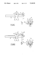
- FIG. 8a, 8b, 8c, 8d are four diagrammatic views, similar to that of FIG. 4, illustrating the characteristic steps in the use of the installation and relative positions of its component members.
- FIG. 9 is a diagrammatic sectional view along the line IX--IX of FIG. 4, illustrating one embodiment of the laser-beam return device.
- FIGS. 10 and 11 are two diagrammatic views, from the front and from the side respectively, of a coating station of an installation according to the invention.
- FIGS. 12a to 12j are ten diagrammatic views illustrating the successive steps of the coating.
- FIG. 13 is a diagrammatic top view of the coating station of FIGS. 10 and 11.
- the invention relates to an installation for marking the surface of a cheese or meat product (1), for the purpose of making one or more surface marks (2) on the outer face of this food product.
- the installation according to the invention is intended for carrying out the process described in the document FR 2,621,529, to which document express reference is made.
- the installation is intended for making a plurality of marks (2) on the upper face (3a) and on the lateral face (3b) respectively of the food product (1).
- the food product (1) is shown with a general flattened cylindrical shape. It goes without saying, however, that other shapes are also possible.
- the installation comprises a laser (4), means (5) for supporting the food product (1) and means capable of obtaining a transverse sweep, combined with a relative longitudinal sliding, of the laser beam F coming from the laser (4) in relation to the supporting means (5), more particularly in relation to the food products (1) which they support.
- the installation also comprises a removable mask (6) intended to be interposed in the path of the laser beam F and having apertures (7), the edges of which correspond to the contours of the mark (2) to be made.
- the installation comprises at least one and usually a plurality of laser marking stations (8).
- laser marking station (8) is meant an assembly forming a unit in which food products (1) can be treated in succession in such a way that the mark or marks obtained by means of the laser beam (F) and the mask (6) are made on their faces, (3a), 3b).
- the installation comprises a station (9) for coating the food product (1) to be marked with flour or its equivalent (10).
- This coating station (9) is located upstream of the marking station or marking stations (8).
- coating station (9) is meant an assembly in which a food product (1) can be treated so as to be coated appropriately on its outer faces with flour or its equivalent (10). It was found, in fact, that the quality of the coating of the food product (1) with flour or its equivalent (10) had an influence on the quality of the laser marking made subsequently.
- FIGS. 2 to 9 illustrate the laser marking.
- a laser marking station (8) comprises a horizontal linear table (11) supporting a carriage (12) mounted horizontally slidably along an axis xx. It subsequently comprises means for receiving the laser beam coming from the laser (4) and for reflecting this beam along the axis xx in the front direction, forming as a whole a laser-beam projection assembly (13).
- the station (8) also has a first device (14) for reflecting the laser beam vertically downwards, carried frontally by the carriage (12) on the axis xx, so as to receive the laser beam exiting from the projection assembly (13).
- a second device (15) for reflecting the laser beam, on the one hand along an axis x'x' parallel to and located vertically below and in line with the axis xx, and on the other hand in the front direction, is arranged proximally and frontally relation to the table (11) (see FIG. 4).
- a horizontal tray (16) for supporting the food product (1) to be marked is mounted pivotably about a vertical axis zz located substantially in the mid-plane xxx'x', this supporting tray (16) being located distally and frontally in relation to the table (11), whilst at the same time being substantially coplanar with the second return device (15).
- the distal position is the furthest away from the table (11) in the front direction, whilst the proximal direction is longitudinally the nearest to the table.
- the laser marking station (8) also comprises means (17) for driving the supporting tray (16) to pivot about its axis zz; means for driving the carriage to slide along its axis xx, these not being shown explicitly in the drawings because they are integrated both in table (11) and in the carriage (12); and finally, means (not shown) of controlling the means (17) for driving the supporting tray (16) and the means for driving the carriage (12) to slide along its axis xx.
- the linear table (11) supports the projection assembly (13) and the carriage (12) in such a way that the latter is mounted horizontally slidably along an axis yy perpendicular to the axis xx.
- the installation then has means for driving the carriage (12) and the projection assembly (13) to slide along the axis yy.
- These driving means are not shown in the figures because they are integrated in the linear table (11), in the carriage (12) and in the assembly (13).
- the control means then also control the means for driving the projection assembly (13) and for driving the carriage (12) to slide along the axis yy.
- the installation comprises a plurality of laser marking stations (8), (8).
- FIGS. 2 and 3 show two laser marking (8a), (8b).
- the various laser marking stations (8a), (8b) have a linear table (11), a carriage (12), a laser-beam projection assembly (13) and a first single reflector device (14) common to all the laser marking stations.
- the installation comprises as many second reflector devices (15) as supporting trays (16) as stations.
- Each of the laser marking stations (8a), (8b) has a midplane which is a vertical plane containing the axes xx and zz.
- the various mid-planes corresponding to the various stations (8a), (8b) are parallel to and spaced from one another along the common axis yy.
- the sliding axis yy serves, on the one hand, for making the laser marking of a mark (2) on the upper face (3a) of a food product (1), this mark extending parallel to the axis yy, and, at the same time, for transferring the integral assembly formed by the carriage (12) and the projection assembly (13) from one station to another.
- this reflector device (18) for returning the laser-beam carried by the projection assembly (13), this reflector device (18) receiving an incident laser beam coming from the laser (4) along the axis yy and making it possible, at the exit, to reflect the laser beam (F) along the axis xx towards the first reflector device (14).
- the incident laser beam comes from a protective tube mounted at the exit of the laser (4) and arranged laterally in relation to the table (11).
- the incident laser beam in the protective tube (19) can remain stationary as a whole, the installation being designed to allow marks to be made on the upper and lateral faces (3a), (3b) of a food product (1) and even of a plurality of food products in the various laser marking stations (8a), (8b), as already mentioned.
- the linear table (11) extends essentially transversely. It is supported by a mount (20). This linear table (11) has guides and driving means, such as pulleys, racks, etc.
- a horizontal stage (21) is mounted on the linear table (11) slidably in the transverse direction yy.
- Mounted side by side on this stage (21) are, on the one hand, fastened rigidly, the projection assembly (3) and, on the other hand, mounted longitudinally slidably, a linear board (22) extending in the longitudinal direction.
- This linear board (22) has sliding and driving members of the same general type as those of the table (11). In its free front end part, the linear board (22) forms the carriage (12).
- front part is meant that which, in a longitudinal direction, is on the side where the supporting tray or supporting trays (16) are located.
- the opposite part, on the other side of the linear table (11), is called the rear part.
- the projection assembly (13) comprises an outer housing (23) fastened to the stage (21) equipped with a lateral orifice (24) located opposite the protective tube (19) and, on its front face, with a projection tube (25) adjacent to a front orifice (26).
- the two orifices (24), (26) communicate via the space within the housing (23), in which is mounted a member (27) for reflecting the laser beam, such as a vertical plane mirror inclined at 45° to the axes xx and yy.
- the first reflector device (14) likewise consists of a plane mirror extending parallel to the axis yy and at 45° relative to the axes xx and zz.
- the second laser-beam reflector device (15) likewise consists of a mirror having some concavity so as to focus the laser beam towards the food product (1) to be marked.
- the general plane of the mirror of the second reflector device (15) extends substantially parallel to that of the first reflector device, whilst at the same time being offset relative to the latter downwards and towards the linear table (11).
- the mirrors forming the reflector members or devices (14), (15), (27) can be produced in any suitable way.
- these members or devices are mounted by means of a quick-assembly device, so that they can easily be replaced if necessary.
- the second reflector device (15) is arranged in relation to the linear table (11) in such a way that the incident vertical laser beam reaching it does not interfere with the other component members of the installation.
- the supporting tray (16) is, for example, a circular tray driven by a motor (17) placed underneath it. Such a tray (16) is fastened to an axle (28) carried by bearings (29) forming part of a stand of the laser marking station (8).
- a substantially coplanar arrangement of the supporting tray (16) and of a second reflector device (15) is meant that the transverse horizontal centre line of the second reflector device (15) is located horizontally in line with the mask (6) when it is placed on the supporting tray (16), as described in more detail later.
- the supporting tray (16) or the various supporting trays of the various laser marking stations (8), (8) are arranged at the front in the installation so as to allow access.
- the means for driving the carriage (12) to slide along its sliding axis xx make it possible for the carriage (12) to slide between two end positions, namely a distal position and a proximal position designated respectively by (D) and (P) in FIGS. 2 and 4. These notions of distal and proximal are to be understood in relation to the table (11).
- the first return device (14) is located vertically above and in line with the supporting tray (16) or with the food product (1) or with the mask (6), especially its upper face.
- the first reflector device is located vertically above and in line with the second reflector device (15).
- a suction port (30) for the vapours and smoke which can occur as a result of the laser marking is intended to be coupled to a discharge suction device (31).
- at least one suction port (30) is provided for each supporting tray (16).
- Such a suction port (30) is, in the first place, located at a horizontal level higher than the supporting tray (16) and, where appropriate, the mask (6) which it supports.
- a suction port (30) is located in a horizontal plane and offset relative to the supporting tray (16), to allow the mask (6) to be put in place and removed parallel to the axis zz of the supporting tray (16).
- the suction port (30) is not located exactly in line with the supporting tray (16).
- the suction port (30) is offset downstream of the impact of the laser beam (F) on the mask (6) and/or the food product (1) and in relation to the direction of rotation of the supporting tray (16).
- FIG. 5h shows (32), the impact of the laser beam on the mask (6) and that a zone first subjected to the impact of the laser beam (32) subsequently passes into the vicinity of the suction port (30) in view of the direction of rotation of the supporting tray (16) represented by the arrow (R).
- FIG. 7 shows one possible embodiment of a mask (6).
- a mask comprises, on the one hand, a lateral wall (33) of general cylindrical or prismatic shape, of which the axis is substantially coaxial with the axis zz of this supporting tray (16), when the mask (2) is in position on the supporting tray (16).
- the mask (6) comprises, on the other hand, an upper horizontal wall (34) fastened to the upper free edge (35) of the lateral wall (33), the lower free edge (36) of which is intended to rest on the supporting tray (16) when the mask (6) is in position.
- the notions of upper, lateral, lower, etc. refer, here, to the situation where the mask (6) is in the normal position of use on the supporting tray (16).
- Such a mask then forms a kind of bell covering the food product (1), the apertures (7) being made in the walls (33), (34).
- the upper horizontal wall (34) has a radial extension (37) directed outward, especially in the form of a cylindrical ring, which makes it possible simultaneously to assist the dissipation of heat caused by the laser impact and, on the other hand, to grasp the mask (6), especially manually, without getting burnt.
- a protective plate (38) made of a material which can prevent the passage of the laser beam (F), this plate being of sufficient size and being vertically arranged perpendicularly to the longitudinal direction.
- a vertical protective wall (39) made of a material which can retard the passage of the laser beam (F) and extending sufficiently both in the transverse direction and in the vertical direction.
- One or more orifices (40) are made in the vertical wall (39), especially opposite each marking station (8a), (8b), meaning that there are then as many orifices (40) as there are marking stations (8).
- One orifice (40) makes it possible to introduce and extract the food product (1) to be marked and the mask (6).
- This orifice (40) can be closed by a door (41).
- the door (41) is for example, mounted vertically slidably on and against the vertical wall (39) by means of lateral sliding members (42).
- the door (41) has an actuating handle (43), especially in its lower part.
- the door (41) is mounted in equilibrium, and for this purpose there can be fastened to it lateral cables (44) extending vertically upwards and passing, in the upper part, over grooved return pulleys (45) of horizontal and transverse axis (46).
- the cables (44) support a counterweight (47) which thus ensures the balancing of the door (41).
- a safety device (48) carried by the wall (39) and the door (41), in such a way that the marking station can function only when the door (41) is closed.
- a safety device (48) carried by the wall (39) and the door (41), in such a way that the marking station can function only when the door (41) is closed.
- FIGS. 5a to 5j and 8a to 8d The functioning of a laser marking station, as just described, will now be dealt with, and for this purpose reference is made to FIGS. 5a to 5j and 8a to 8d.
- the assembly is initially at a standstill
- the carriage (12) is in the proximal position, to allow convenient access to the supporting tray (16).
- the carriage (12) is in the distal position from the outset.
- the user can open the door (41), This operation is made all the easier because there are means for balancing this (44), (45), (46) and (47).
- the supporting tray (16) is thus free in this state (FIG. 5A).
- the user can put in place the food product (1) with its free upper face (3a) on top (FIG. 5b). He can subsequently place the mask (6) in the manner of a bell, on the supporting tray (16) and round the food product (1).
- This operation is made all the easier because the mask (6) has a radial extension (37). If appropriate, marks or a groove are provided on the supporting tray (16), making it possible to position the mask (6) perfectly in relation to the supporting tray (16).
- the laser beam F coming from the laser (4) first follows a transverse path of axis yy through the tube (19) and is then reflected along the axis xx by the reflector member (27). It then strikes the first reflector device (14) which deflects the laser beam vertically downwards parallel to the axis zz of the supporting tray (16). Because the carriage (12) is in its distal position, the laser beam (F) reflected by the first device (14) meets the upper horizontal wall (34) of the mask (6).
- the driving and control means are designed so that, with the supporting tray (16) then being immobile, the carriage (12) is moved to slide from its end distal position along the axis xx alternately in one direction and the other over a small stroke at most equal to that of the mask (6) and, together with the projection assembly (13), along the axis yy over a stroke in successive steps which is likewise small and at most equal to that of the mask (6).
- This stroke of the carriage (12) along the axis xx is represented in FIG. 8b by the distance C1. It also appears in FIG. 5e.
- the stroke along the axis yy is represented in FIG. 5e by the distance C2.
- the movements of the carriage (12), combined along the axis xx and along the axis yy, are executed at such a speed that an overlapping sliding impact can be obtained, as described in the document FR 2,624,529.
- the laser beam F strikes either the upper horizontal wall (34), at the point where it is without an aperture (7), or the upper face (3a) of the product (1), leaving a mark (2).
- the production of the mark (2) causes release of smoke and vapours which can escape from the confined space defined by the mask (6) placed on the supporting tray (16) by means of the apertures (7). These vapours and smoke are removed by the suction port (30) and eliminated by means of the device (31) (FIG. 5F).
- the relative positions of the second reflector device (15) and of the supporting tray (16) and the dimensions of the mask (6), especially in the axle direction along the axis zz, are such that the laser beam in the axis x'x' meets the lateral wall (33) of the mask (6).
- the carriage (12) is then moved from its proximal position P to slide along the axis xx over a small stroke represented in FIG. 8d by the distance C3, in such a way that the impact of the laser beam reflector by the first reflector device (14) slides along the second reflector device (15) and passes from its lower part to its upper part, or vice versa. It follows from this that the axis x'x' is moved between two end positions, namely lower (FIG.
- the impact (32) of the laser beam can be an impact within the meaning of the document FR 2,621,529, capable of making the desired marks (2) over the entire periphery of the food product (1).
- the support tray (16) can be stopped, and the carriage (12) can be maintained in its proximal position, with the proviso of what was said above.
- the door (41) can be opened. The user can remove the mask (6), without risking burning himself, by means of the radial extension (37) and then the food product (1) having the marks (2) (FIGS. 5i and 5j).
- FIG. 6 illustrates such a marked product, the marks made being purely indicative and with the possibility of including dot, line or surface marks.
- the various stations (8a), (8b) are in different states of progress of the process, so that, for example, during the marking period of one station (8a), the user puts in place or, on the contrary, removes the food product (1) and the mask (6) from the adjacent station (8b).
- FIGS. 1 and 10 to 13 as regards a station for coating with flour or its equivalent (10).
- Such a coating station is located upstream of a laser marking station (8), and it comprises an enclosure (50) of general parallelepipedal shape, having a front orifice (51) allowing the loading and unloading of the food product (1) to be coated.
- a supporting tray (52) mounted pivotably about a vertical axle (53).
- the supporting tray (52) is carried by means of bearings (not shown) and is arranged in the lower part of the enclosure (50).
- Means (54) for driving the supporting tray (52) to pivot about its axle (53) are provided especially underneath the enclosure (50). These can be, for example, a motor or a geared motor.
- the coating station also comprises at least one glaze-spraying gun (55) associated with glaze delivery means (56).
- the gun (55) is located at a higher level than that of the supporting tray (52) and is generally directed towards this.
- the coating station also possesses at least one gun (57) for spraying flour (10) or its equivalent. Associated with this gun (57) are means (58) for delivering flour or its equivalent (10).
- the gun (57) is located at a higher level than the supporting tray (52) and is directed towards this.
- the two guns (55) and (57) are located in the immediate vicinity of one another, their axes being substantially parallel to one another or converging slightly in the direction of the supporting tray (52).
- the coating station (9) also possesses means of controlling the driving of the supporting tray (54) and of the guns (55), (57).
- control means are arranged so that successively: with the supporting tray (52) initially being at a standstill and empty of any food product (1) to be coated (FIG. 12A), the user can place on it a food product (1) to be coated (FIG. 12B).
- the supporting tray (52) is then driven in rotation about its axle (53) by the driving means (54) (FIG. 12C).
- first glaze alone is sprayed (FIG. 12D) and then glaze and flour or its equivalent (10) are sprayed simultaneously (FIG. 12e), and then finally flour or its equivalent alone is sprayed (FIG. 12f).
- the spraying of glaze and the spraying of flour are shown diagrammatically in two opposite directions only, to make it easier to understand the functioning.
- the glaze spray stream and the flour spray stream are intimately mixed with one another as a result of the proximity and parallel or slightly convergent nature of the guns (55), (57).
- the supporting tray (52) can be brought to a standstill and the food product (1) thus coated removed (FIG. 12g).
- drying station consisting, for example, of an infrared tunnel (60), through which passes the food product (1) supported, for example, by an endless conveyor belt (61) (FIG. 12h).
- the food product (1) thus coated on its preceding upper face and its lateral face can be overturned (FIG. 12i), the previous upper face becoming the current lower face, and vice versa, and the coating operation can be recommenced in such a way that the entire food product (1) is coated.
- the coating station also has a suction port (62) located in the enclosure (50) and coupled to a discharge suction device (63).
- a suction port (62) located in the enclosure (50) and coupled to a discharge suction device (63).
- a suction port (62) located in the enclosure (50) and coupled to a discharge suction device (63).
- a coating station (9) also possesses a device (64) for spraying water especially on the inner faces of the vertical walls of the enclosure (50).
- the bottom (65) of the enclosure (50) is inclined, and it has a low point where there is a discharge (66) for the streaming water coming from the device (64).
- the suction ports (62a), (62b) are preferably diametrically opposite one another, and the supporting tray (16) has the general shape of a star, so that most of the outer face of the food product (1) is free and therefore coated with glaze and with flour or its equivalent (10). Moreover, the tray (16) makes it easier to pick up the cheese.
- the invention can have many other embodiments.
Landscapes
- Engineering & Computer Science (AREA)
- Physics & Mathematics (AREA)
- Optics & Photonics (AREA)
- Plasma & Fusion (AREA)
- Mechanical Engineering (AREA)
- Life Sciences & Earth Sciences (AREA)
- Wood Science & Technology (AREA)
- Environmental Sciences (AREA)
- Animal Husbandry (AREA)
- Zoology (AREA)
- Food Science & Technology (AREA)
- Laser Beam Processing (AREA)
- Dairy Products (AREA)
- General Preparation And Processing Of Foods (AREA)
- Treatments Of Macromolecular Shaped Articles (AREA)
- Meat, Egg Or Seafood Products (AREA)
- Dot-Matrix Printers And Others (AREA)
- Thermal Transfer Or Thermal Recording In General (AREA)
Applications Claiming Priority (2)
| Application Number | Priority Date | Filing Date | Title |
|---|---|---|---|
| FR8912982A FR2652541B1 (fr) | 1989-10-04 | 1989-10-04 | Installation pour le marquage superficiel par laser d'un produit alimentaire fromager ou charcutier . |
| FR8912982 | 1989-10-04 |
Publications (1)
| Publication Number | Publication Date |
|---|---|
| US5120928A true US5120928A (en) | 1992-06-09 |
Family
ID=9386086
Family Applications (1)
| Application Number | Title | Priority Date | Filing Date |
|---|---|---|---|
| US07/586,946 Expired - Lifetime US5120928A (en) | 1989-10-04 | 1990-09-24 | Installation for the laser marking of the surface of a cheese or delicatessen food product |
Country Status (12)
| Country | Link |
|---|---|
| US (1) | US5120928A (de) |
| EP (1) | EP0421837B1 (de) |
| JP (1) | JP2667569B2 (de) |
| AT (1) | ATE79515T1 (de) |
| AU (1) | AU629691B2 (de) |
| BR (1) | BR9004943A (de) |
| DD (1) | DD299263A5 (de) |
| DE (1) | DE69000264T2 (de) |
| ES (1) | ES2034843T3 (de) |
| FR (1) | FR2652541B1 (de) |
| PL (1) | PL165116B1 (de) |
| RU (1) | RU1838157C (de) |
Cited By (34)
| Publication number | Priority date | Publication date | Assignee | Title |
|---|---|---|---|---|
| DE4326969A1 (de) * | 1993-08-11 | 1995-02-16 | Siemens Nixdorf Inf Syst | Verfahren zur Beschriftung von schrägen Flächen, insbesondere Tastenkappen, mittels Laser |
| US5653900A (en) * | 1991-01-17 | 1997-08-05 | United Distillers Plc | Dynamic laser marking |
| DE19646813A1 (de) * | 1996-01-10 | 1997-08-21 | Hans Hnatek | Verfahren zum Erzeugen von Bildern und Schriften in pastösen Eßwaren wie Fleisch-, Teig- oder Süßwaren oder anderen Fertigprodukten der Lebensmittelindustrie mittels eines CO2-Laserbeschriftungssystems |
| US5660747A (en) * | 1994-11-04 | 1997-08-26 | Atrion Medical Products, Inc. | Method of laser marking of produce |
| DE19730887A1 (de) * | 1997-07-18 | 1999-01-21 | Hans Hnatek | Verfahren und Vorrichtung zum Aufbringen von Bildern auf Produkte |
| US5897797A (en) * | 1994-11-04 | 1999-04-27 | Atrion Medical Product. Inc. | Produce marking system |
| DE19851379A1 (de) * | 1998-11-07 | 2000-05-11 | Kemper Gmbh & Co H | Vorrichtung und Verfahren zum Erzeugen von Bildern, Schriften, Muster o. dgl. auf der Oberfläche von Lebensmitteln |
| US6172328B1 (en) | 1998-02-17 | 2001-01-09 | Advanced Foliar Technologies, Inc. | Laser marking of plant material |
| US6180914B1 (en) | 1998-02-17 | 2001-01-30 | Advanced Foliar Technologies, Inc. | Laser marking of foliage and cigars |
| US20030206227A1 (en) * | 2000-04-18 | 2003-11-06 | Laserink, A California Corporation | Printing a code on a product |
| US20040091588A1 (en) * | 2002-10-31 | 2004-05-13 | Xiaochun Li | Food processing apparatus and method |
| US20050077274A1 (en) * | 2003-10-10 | 2005-04-14 | Neto Jose Barbosa Machado | Marking or engraving means applied over the external surface of meats in general and resulting product |
| US20050088510A1 (en) * | 2003-10-24 | 2005-04-28 | Shlomo Assa | Low angle optics and reversed optics |
| US20050134678A1 (en) * | 2003-12-19 | 2005-06-23 | Kevin Franklin | Striping and clipping correction |
| US20050226975A1 (en) * | 2004-04-13 | 2005-10-13 | Greg Drouillard | Foodstuff marking system |
| FR2870478A1 (fr) * | 2004-05-19 | 2005-11-25 | Syndicat Interprofessionnel De | Dispositif de marquage sur le talon d'un fromage |
| US20050276887A1 (en) * | 2004-06-09 | 2005-12-15 | Eberhard Wiedenmann | Method of marking smoked food products |
| US20060138105A1 (en) * | 2003-01-15 | 2006-06-29 | Eggfusion | Method and apparatus for marking an egg with an advertisement, a freshness date and a traceability code |
| US20060262181A1 (en) * | 2005-05-17 | 2006-11-23 | Robbins Gene A | Laser-based image former operable to form dynamically variable images in objects in single shot events |
| US20070229649A1 (en) * | 2003-01-15 | 2007-10-04 | Parker Bradley E | Method and Apparatus for Marking an Egg with an Advertisement and Freshness Date |
| US20080131563A1 (en) * | 2006-11-30 | 2008-06-05 | Vladek Kasperchik | Food-compatible laser-imageable coatings |
| US20080223834A1 (en) * | 2007-03-16 | 2008-09-18 | Eggfusion, Inc. | Method and apparatus for laser marking objects |
| US20110177208A1 (en) * | 2010-01-20 | 2011-07-21 | Newmarket Impressions, Llc | Systems and methods for processing eggs |
| US20110177217A1 (en) * | 2010-01-20 | 2011-07-21 | Mitchell Barry Chait | Systems and methods for processing eggs |
| US20110176901A1 (en) * | 2010-01-20 | 2011-07-21 | Mitchell Barry Chait | Systems and methods for processing eggs |
| US20110174223A1 (en) * | 2010-01-20 | 2011-07-21 | Mitchell Barry Chait | Systems and methods for processing eggs |
| US20110177206A1 (en) * | 2010-01-20 | 2011-07-21 | Newmarket Impressions, Llc | Systems and methods for processing eggs |
| CN103101325A (zh) * | 2012-12-10 | 2013-05-15 | 海宁伊满阁太阳能科技有限公司 | 农副产品激光标记方法设备及产品 |
| US8455026B2 (en) | 2010-01-20 | 2013-06-04 | Ten Media, Llc | Systems and methods for processing eggs |
| US8823758B2 (en) | 2010-01-20 | 2014-09-02 | Ten Media, Llc | Systems and methods for processing eggs |
| US8871287B2 (en) | 2010-01-20 | 2014-10-28 | Ten Media, Llc | Container for eggs, method and apparatus for arranging and stabilizing eggs in a container |
| DE102014113323A1 (de) * | 2014-09-16 | 2016-03-17 | BMA Automation GmbH | Verfahren und Vorrichtung zur Entfernung einer Kunststoffbeschichtung von einem Lebensmittellaib |
| US9315317B2 (en) | 2012-02-21 | 2016-04-19 | Ten Media, Llc | Container for eggs |
| US10583668B2 (en) | 2018-08-07 | 2020-03-10 | Markem-Imaje Corporation | Symbol grouping and striping for wide field matrix laser marking |
Families Citing this family (9)
| Publication number | Priority date | Publication date | Assignee | Title |
|---|---|---|---|---|
| CH686393A5 (de) * | 1992-03-03 | 1996-03-29 | Leu Anlagenbau Ag | Verfahren und Vorrichtung zur Markierung von Kaeselaiben. |
| IT234940Y1 (it) * | 1994-06-01 | 2000-03-20 | Consorzio Del Formaggio Parmig | Macchina per la marchiatura del formaggio stagionato a crosta dura, come il parmigiano-reggiano |
| NL9401841A (nl) * | 1994-11-04 | 1996-06-03 | Stork Rms Bv | Inrichting voor het aanbrengen van een markeringspatroon op een stuk vlees. |
| NL9402168A (nl) * | 1994-12-20 | 1996-08-01 | Koninkl Verkade N V | Werkwijze voor het aanbrengen van een opschrift of afbeelding op een vast voedingsmiddel. |
| NL1012625C2 (nl) * | 1999-07-16 | 2001-01-17 | Tno | Markeren van producten van dierlijke oorsprong. |
| CN101804742B (zh) * | 2009-02-12 | 2012-01-11 | 北京志恒达科技有限公司 | 一种用于保护激光打标机的保护罩和一种激光打标机柜 |
| US9723836B2 (en) * | 2009-11-19 | 2017-08-08 | Bayer Cropscience Ag | Synergistic pre-emergent and post-emergent weed control compositions and methods of use thereof |
| NL1037562C2 (nl) * | 2009-12-16 | 2011-06-20 | Kaamps Food Productions B V | Werkwijze voor het aanbrengen van een aanduiding op een kaas. |
| CN109332893A (zh) * | 2018-11-24 | 2019-02-15 | 杭州火蓝刀锋科技咨询有限公司 | 一种不锈钢玻璃门体激光无痕焊接装置 |
Citations (6)
| Publication number | Priority date | Publication date | Assignee | Title |
|---|---|---|---|---|
| FR2195408A1 (en) * | 1972-08-11 | 1974-03-08 | Dufour Adrien | Thermal treatment in depth of food prods. - using laser beams on finished prods. to destroy bacteriological activity |
| EP0031239A1 (de) * | 1979-12-19 | 1981-07-01 | Danepak Limited | Bedrucken von Verpackungsmaterial |
| US4410968A (en) * | 1977-03-24 | 1983-10-18 | Thomas Lee Siwecki | Method and apparatus for recording on a disk supported deformable metallic film |
| US4486645A (en) * | 1980-07-03 | 1984-12-04 | Armour Food Company | Process for removing packaging materials from packaged products |
| US4791267A (en) * | 1987-01-28 | 1988-12-13 | Mitsubishi Denki Kabushiki Kaisha | Method of forming identifying indicium on cathode ray tubes |
| FR2621529A1 (en) * | 1987-10-09 | 1989-04-14 | Bongrain Sa | Method for thermal treatment of a food product, in particular a cheese or pork butchery food product; method for marking such a food product, marking apparatus for implementing the method; food product thus treated or marked |
-
1989
- 1989-10-04 FR FR8912982A patent/FR2652541B1/fr not_active Expired - Lifetime
-
1990
- 1990-09-21 EP EP90402620A patent/EP0421837B1/de not_active Expired - Lifetime
- 1990-09-21 AT AT90402620T patent/ATE79515T1/de not_active IP Right Cessation
- 1990-09-21 ES ES199090402620T patent/ES2034843T3/es not_active Expired - Lifetime
- 1990-09-21 DE DE9090402620T patent/DE69000264T2/de not_active Expired - Lifetime
- 1990-09-24 US US07/586,946 patent/US5120928A/en not_active Expired - Lifetime
- 1990-09-25 AU AU63130/90A patent/AU629691B2/en not_active Expired
- 1990-10-02 BR BR909004943A patent/BR9004943A/pt not_active IP Right Cessation
- 1990-10-02 DD DD90344374A patent/DD299263A5/de unknown
- 1990-10-03 RU SU904831348A patent/RU1838157C/ru active
- 1990-10-03 PL PL90287166A patent/PL165116B1/pl unknown
- 1990-10-04 JP JP2265287A patent/JP2667569B2/ja not_active Expired - Lifetime
Patent Citations (6)
| Publication number | Priority date | Publication date | Assignee | Title |
|---|---|---|---|---|
| FR2195408A1 (en) * | 1972-08-11 | 1974-03-08 | Dufour Adrien | Thermal treatment in depth of food prods. - using laser beams on finished prods. to destroy bacteriological activity |
| US4410968A (en) * | 1977-03-24 | 1983-10-18 | Thomas Lee Siwecki | Method and apparatus for recording on a disk supported deformable metallic film |
| EP0031239A1 (de) * | 1979-12-19 | 1981-07-01 | Danepak Limited | Bedrucken von Verpackungsmaterial |
| US4486645A (en) * | 1980-07-03 | 1984-12-04 | Armour Food Company | Process for removing packaging materials from packaged products |
| US4791267A (en) * | 1987-01-28 | 1988-12-13 | Mitsubishi Denki Kabushiki Kaisha | Method of forming identifying indicium on cathode ray tubes |
| FR2621529A1 (en) * | 1987-10-09 | 1989-04-14 | Bongrain Sa | Method for thermal treatment of a food product, in particular a cheese or pork butchery food product; method for marking such a food product, marking apparatus for implementing the method; food product thus treated or marked |
Non-Patent Citations (1)
| Title |
|---|
| French Counterpart Patent Search Report. * |
Cited By (53)
| Publication number | Priority date | Publication date | Assignee | Title |
|---|---|---|---|---|
| US5653900A (en) * | 1991-01-17 | 1997-08-05 | United Distillers Plc | Dynamic laser marking |
| DE4326969A1 (de) * | 1993-08-11 | 1995-02-16 | Siemens Nixdorf Inf Syst | Verfahren zur Beschriftung von schrägen Flächen, insbesondere Tastenkappen, mittels Laser |
| US5660747A (en) * | 1994-11-04 | 1997-08-26 | Atrion Medical Products, Inc. | Method of laser marking of produce |
| US5897797A (en) * | 1994-11-04 | 1999-04-27 | Atrion Medical Product. Inc. | Produce marking system |
| DE19646813A1 (de) * | 1996-01-10 | 1997-08-21 | Hans Hnatek | Verfahren zum Erzeugen von Bildern und Schriften in pastösen Eßwaren wie Fleisch-, Teig- oder Süßwaren oder anderen Fertigprodukten der Lebensmittelindustrie mittels eines CO2-Laserbeschriftungssystems |
| DE19646813C2 (de) * | 1996-01-10 | 1998-07-09 | Hans Hnatek | Verfahren zur Erzeugung von Bildern und Schriftzeichen auf der Oberfläche von schnittfesten Produkten der Lebensmittelindustrie |
| DE19730887A1 (de) * | 1997-07-18 | 1999-01-21 | Hans Hnatek | Verfahren und Vorrichtung zum Aufbringen von Bildern auf Produkte |
| US6172328B1 (en) | 1998-02-17 | 2001-01-09 | Advanced Foliar Technologies, Inc. | Laser marking of plant material |
| US6180914B1 (en) | 1998-02-17 | 2001-01-30 | Advanced Foliar Technologies, Inc. | Laser marking of foliage and cigars |
| DE19851379A1 (de) * | 1998-11-07 | 2000-05-11 | Kemper Gmbh & Co H | Vorrichtung und Verfahren zum Erzeugen von Bildern, Schriften, Muster o. dgl. auf der Oberfläche von Lebensmitteln |
| US20030206227A1 (en) * | 2000-04-18 | 2003-11-06 | Laserink, A California Corporation | Printing a code on a product |
| US20040141052A1 (en) * | 2000-04-18 | 2004-07-22 | Laserink, A California Corporation | Printing a code on a product |
| US6791592B2 (en) | 2000-04-18 | 2004-09-14 | Laserink | Printing a code on a product |
| US6829000B2 (en) | 2000-04-18 | 2004-12-07 | Laserink | Printing a code on a product |
| US20040091588A1 (en) * | 2002-10-31 | 2004-05-13 | Xiaochun Li | Food processing apparatus and method |
| US9511601B2 (en) | 2003-01-15 | 2016-12-06 | Ten Media, Llc | Methods and apparatus for storing and retrieving information relating to edible objects |
| US8544739B2 (en) | 2003-01-15 | 2013-10-01 | Ten Media, Llc | Methods and apparatus for storing and retrieving information relating to edible objects |
| US7951409B2 (en) | 2003-01-15 | 2011-05-31 | Newmarket Impressions, Llc | Method and apparatus for marking an egg with an advertisement, a freshness date and a traceability code |
| US20070229649A1 (en) * | 2003-01-15 | 2007-10-04 | Parker Bradley E | Method and Apparatus for Marking an Egg with an Advertisement and Freshness Date |
| US20060138105A1 (en) * | 2003-01-15 | 2006-06-29 | Eggfusion | Method and apparatus for marking an egg with an advertisement, a freshness date and a traceability code |
| US20070048420A1 (en) * | 2003-10-10 | 2007-03-01 | Neto Jose B M | Meat products marked or engraved on their external suface and method for making same |
| US20050077274A1 (en) * | 2003-10-10 | 2005-04-14 | Neto Jose Barbosa Machado | Marking or engraving means applied over the external surface of meats in general and resulting product |
| GB2406779B (en) * | 2003-10-10 | 2007-11-14 | Jose Barbosa Machado Neto | A marking or engraving means applied over the external surface of meats in general and resulting product |
| US20050088510A1 (en) * | 2003-10-24 | 2005-04-28 | Shlomo Assa | Low angle optics and reversed optics |
| US20050134678A1 (en) * | 2003-12-19 | 2005-06-23 | Kevin Franklin | Striping and clipping correction |
| US20050226975A1 (en) * | 2004-04-13 | 2005-10-13 | Greg Drouillard | Foodstuff marking system |
| FR2870478A1 (fr) * | 2004-05-19 | 2005-11-25 | Syndicat Interprofessionnel De | Dispositif de marquage sur le talon d'un fromage |
| US20050276887A1 (en) * | 2004-06-09 | 2005-12-15 | Eberhard Wiedenmann | Method of marking smoked food products |
| US20070222556A1 (en) * | 2005-05-17 | 2007-09-27 | Robbins Gene A | Tracking system for distributable objects which are marked in single laser shot events with dynamically variable images |
| US7375739B2 (en) | 2005-05-17 | 2008-05-20 | Vardex Laser Corporation | Image management system operable to manage the formation of dynamically variable images in objects in single shot events |
| US20060262180A1 (en) * | 2005-05-17 | 2006-11-23 | Robbins Gene A | Object processing assembly operable to form dynamically variable images in objects in single shot events |
| US20060262182A1 (en) * | 2005-05-17 | 2006-11-23 | Robbins Gene A | Image management system operable to manage the formation of dynamically variable images in objects in single shot events |
| US20060262181A1 (en) * | 2005-05-17 | 2006-11-23 | Robbins Gene A | Laser-based image former operable to form dynamically variable images in objects in single shot events |
| US20080131563A1 (en) * | 2006-11-30 | 2008-06-05 | Vladek Kasperchik | Food-compatible laser-imageable coatings |
| US20080223834A1 (en) * | 2007-03-16 | 2008-09-18 | Eggfusion, Inc. | Method and apparatus for laser marking objects |
| US8884185B2 (en) | 2007-03-16 | 2014-11-11 | Ten Media, Llc. | Method and apparatus for laser marking objects |
| US8084712B2 (en) | 2007-03-16 | 2011-12-27 | TEN Medias LLC | Method and apparatus for laser marking objects |
| US20110177206A1 (en) * | 2010-01-20 | 2011-07-21 | Newmarket Impressions, Llc | Systems and methods for processing eggs |
| US8657098B2 (en) | 2010-01-20 | 2014-02-25 | Ten Media, Llc | Systems and methods for processing eggs |
| US20110177208A1 (en) * | 2010-01-20 | 2011-07-21 | Newmarket Impressions, Llc | Systems and methods for processing eggs |
| US8455026B2 (en) | 2010-01-20 | 2013-06-04 | Ten Media, Llc | Systems and methods for processing eggs |
| US8455030B2 (en) | 2010-01-20 | 2013-06-04 | Ten Media, Llc | Systems and methods for processing eggs |
| US8499718B2 (en) | 2010-01-20 | 2013-08-06 | Ten Media, Llc | Systems and methods for processing eggs |
| US20110176901A1 (en) * | 2010-01-20 | 2011-07-21 | Mitchell Barry Chait | Systems and methods for processing eggs |
| US20110174223A1 (en) * | 2010-01-20 | 2011-07-21 | Mitchell Barry Chait | Systems and methods for processing eggs |
| US8715757B2 (en) | 2010-01-20 | 2014-05-06 | Ten Media, Llc | Systems and methods for processing eggs |
| US8823758B2 (en) | 2010-01-20 | 2014-09-02 | Ten Media, Llc | Systems and methods for processing eggs |
| US8871287B2 (en) | 2010-01-20 | 2014-10-28 | Ten Media, Llc | Container for eggs, method and apparatus for arranging and stabilizing eggs in a container |
| US20110177217A1 (en) * | 2010-01-20 | 2011-07-21 | Mitchell Barry Chait | Systems and methods for processing eggs |
| US9315317B2 (en) | 2012-02-21 | 2016-04-19 | Ten Media, Llc | Container for eggs |
| CN103101325A (zh) * | 2012-12-10 | 2013-05-15 | 海宁伊满阁太阳能科技有限公司 | 农副产品激光标记方法设备及产品 |
| DE102014113323A1 (de) * | 2014-09-16 | 2016-03-17 | BMA Automation GmbH | Verfahren und Vorrichtung zur Entfernung einer Kunststoffbeschichtung von einem Lebensmittellaib |
| US10583668B2 (en) | 2018-08-07 | 2020-03-10 | Markem-Imaje Corporation | Symbol grouping and striping for wide field matrix laser marking |
Also Published As
| Publication number | Publication date |
|---|---|
| ATE79515T1 (de) | 1992-09-15 |
| EP0421837B1 (de) | 1992-08-19 |
| PL165116B1 (pl) | 1994-11-30 |
| ES2034843T3 (es) | 1993-04-01 |
| EP0421837A1 (de) | 1991-04-10 |
| FR2652541B1 (fr) | 1992-01-03 |
| DE69000264T2 (de) | 1993-03-11 |
| RU1838157C (ru) | 1993-08-30 |
| FR2652541A1 (fr) | 1991-04-05 |
| JPH03211068A (ja) | 1991-09-13 |
| DE69000264D1 (de) | 1992-09-24 |
| DD299263A5 (de) | 1992-04-09 |
| JP2667569B2 (ja) | 1997-10-27 |
| AU6313090A (en) | 1991-04-11 |
| AU629691B2 (en) | 1992-10-08 |
| BR9004943A (pt) | 1991-09-10 |
Similar Documents
| Publication | Publication Date | Title |
|---|---|---|
| US5120928A (en) | Installation for the laser marking of the surface of a cheese or delicatessen food product | |
| EP1542808B1 (de) | Fortschrittliche beschichtungsvorrichtung und solches verfahren | |
| EP0482255B1 (de) | Tunnelofen mit gezwungener Konvektion | |
| CA2084637C (en) | Method of and apparatus for di can surface treatment | |
| US4311111A (en) | Apparatus for painting a multiplicity of parts together | |
| CA2210253C (en) | Contact lens inverting apparatus and method | |
| US4481875A (en) | Bulb peeling apparatus | |
| CN111432993B (zh) | 分配机雾气管理组件 | |
| CN112974178A (zh) | 一种门扇喷涂线的喷涂方法 | |
| JP2005523055A (ja) | 自動グリル | |
| US6837933B2 (en) | Apparatus for surface coating of small parts | |
| KR100282563B1 (ko) | 기판처리방법및처리장치 | |
| US2346549A (en) | Mechanism for handling closure blanks | |
| US20190329991A1 (en) | Carrier For Holding A Plurality Of Articles | |
| GB2161294A (en) | Process and apparatus for preparing fried sausage products | |
| US3730032A (en) | Bread and pastry processing apparatus | |
| DE747725C (de) | Verfahren zum Lackieren und Trocknen von Konservendosen und aehnlichen Gefaessen | |
| NL1015529C2 (nl) | Werkwijze en inrichting voor het vermeerderen van weefseldelen. | |
| CN112203796B (zh) | 用于加工纸板的装置和方法 | |
| EP1189515B1 (de) | Verfahren und vorrichtung zum markieren von brot | |
| JPS6010709B2 (ja) | 鱗茎の皮剥装置 | |
| GB2233880A (en) | Removing unwanted leaves from cabbages | |
| RU2094198C1 (ru) | Лазерный технологический комплекс для обработки крупногабаритных объектов | |
| EP1290954A1 (de) | Verfahren und Vorrichtung zur Oberflächensterilisierung von Milchprodukten | |
| AU626239B2 (en) | Forced convection tunnel oven |
Legal Events
| Date | Code | Title | Description |
|---|---|---|---|
| STCF | Information on status: patent grant |
Free format text: PATENTED CASE |
|
| FEPP | Fee payment procedure |
Free format text: PAYOR NUMBER ASSIGNED (ORIGINAL EVENT CODE: ASPN); ENTITY STATUS OF PATENT OWNER: LARGE ENTITY |
|
| FPAY | Fee payment |
Year of fee payment: 4 |
|
| FPAY | Fee payment |
Year of fee payment: 8 |
|
| FPAY | Fee payment |
Year of fee payment: 12 |
|
| FEPP | Fee payment procedure |
Free format text: PAYOR NUMBER ASSIGNED (ORIGINAL EVENT CODE: ASPN); ENTITY STATUS OF PATENT OWNER: LARGE ENTITY Free format text: PAYER NUMBER DE-ASSIGNED (ORIGINAL EVENT CODE: RMPN); ENTITY STATUS OF PATENT OWNER: LARGE ENTITY |
|
| REMI | Maintenance fee reminder mailed |