US5111672A - Weft thread insertion arrangement - Google Patents
Weft thread insertion arrangement Download PDFInfo
- Publication number
- US5111672A US5111672A US07/588,654 US58865490A US5111672A US 5111672 A US5111672 A US 5111672A US 58865490 A US58865490 A US 58865490A US 5111672 A US5111672 A US 5111672A
- Authority
- US
- United States
- Prior art keywords
- carriage
- computer
- arrangement
- servomotor
- accordance
- Prior art date
- Legal status (The legal status is an assumption and is not a legal conclusion. Google has not performed a legal analysis and makes no representation as to the accuracy of the status listed.)
- Expired - Lifetime
Links
Images


Classifications
-
- D—TEXTILES; PAPER
- D04—BRAIDING; LACE-MAKING; KNITTING; TRIMMINGS; NON-WOVEN FABRICS
- D04B—KNITTING
- D04B23/00—Flat warp knitting machines
- D04B23/12—Flat warp knitting machines with provision for incorporating unlooped wefts extending from selvedge to selvedge
Definitions
- the present invention relates to a weft thread provision arrangement for the weft thread magazine of a warp knitting machine, and, in particular, to a weft carriage carrying weft threads between a pair of transport means for transporting the laid weft threads to a needle bed, the weft carriage being driven by a drive means, in dependence upon the main shaft of a warp knitting machine.
- the weft carriage is driven from the main shaft by a mechanical gear unit (either with a reduction gear arrangement and/or a crank mechanism driven from the main shaft).
- the motion path formula is strictly prescribed and generally corresponds to a sinusoidal speed/time relationship of the weft carriage. This gives rise to uneven loads on the weft threads pulled from the creel spools.
- the thread takeoff speed does not correspond to the speed of the weft carriage; for example, when the thread sheet is pulled over a common turning roller located above the path of the weft threads.
- roller delivery arrangement to the weft thread provision arrangements of the prior art.
- This roller delivery arrangement is located between the creel spools and the thread guides.
- the drive of the roller delivery arrangement is continually adjustable to take into account the speed of the weft carriage and its position at a particular point in time.
- the drive speed of the delivery means can be pre-set in dependence upon the speed and position of the weft carriage, by means of a computer arrangement equipped with a program storage means
- a roller delivery means however requires additional expenditure in construction.
- an object of the present invention is to provide a weft thread provision arrangement of the type generally described in the prior art, but without a roller delivery means, and with a means for taking into account the material properties of the weft threads or the conditions of the thread provision. Specifically, an object is to deliver weft threads with lower tension variations, and lower peak tensions than was heretofore possible.
- a weft thread insertion arrangement for the weft thread magazine of a warp knitting machine
- the warp knitting machine is adapted to receive weft thread and has a main shaft and a needle bed.
- the weft thread insertion arrangement has an insert carriage for laying weft thread and two forwarding means for forwarding to the needle bed the weft threads laid by the insert carriage
- a drive means for driving the insert carriage to travel between the two forwarding means.
- the drive means is adapted to be regulated by the main shaft of the warp knitting machine
- the drive means includes a computer provided with at least one data storage means and programed to process data under at least one predetermined movement path formula.
- a servomotor is coupled to the computer.
- the weft thread insertion arrangement also has a sensor coupled to the computer for providing thereto a sensor signal responsive to the number of revolutions and the angular displacement position of the main shaft to enable the computer to compute from the sensor signal a target drive speed value for the servomotor based upon the sensor signal and based upon the predetermined movement path formula.
- the drive means employs a computer and a servomotor controlled thereby.
- the computer is provided with a storage means at least containing the motion path formula
- the preferred sensor is provided for the determination of the main shaft data, including at least the number of rotations and the rotational position.
- the computer can determine the required drive speed of the servomotor by considering these main shaft data as well as the data inherent in the motion path formula.
- the back and forth movement of the weft insert carriage must still be carried out within a predetermined cycle of time but within each segment of the laying cycle the weft insert carriage can be driven with an appropriate speed that would be optimal for the weft threads utilized.
- the drive speed is not dependent upon a particular function which is determined by the mechanical gear unit between the main shaft and the weft carriage. Rather, the utilization of a computer, in particular a digital computer, by utilizing the stored data of the motion path formula, permits entirely new speed patterns to be utilized.
- the initial phase that is to say, after the change of direction of the weft insert carriage, in contrast to the sinusoidal (speed/time) function, there may be provided an accelerated or protracted start up.
- the motion path function can also be changed. This may be either a new function entered into the storage means via a keyboard, or the selection from the plurality of previously stored functions. Thus, all that is required is a simple keyboard input or even just a single key stroke in order to make the change necessary to work with other weft threads.
- the position signalling means comprises a path distance measuring means and a reference signal transducer, which is activated when the weft insert carriage takes up a predetermined reference position.
- a null point in the measuring path is established so that the path measurement becomes increasingly accurate with each laying cycle.
- the computer may be provided as part of a control circuit for controlling the position of the weft insert carriage.
- the computer may utilize the main shaft data and the motion path function parameters, to calculate a desired position value. This value may be compared with the actual position value generated by the position signaller and thus, in dependence upon the deviation from the formula, the drive speed may be set. This gives rise to a high level of accuracy while requiring no additional hardware, since a modern computer can take over these additional functions rather readily.
- a drive amplifier which is supplied by the computer with a desired value for the speed.
- the servomotor is provided with a transducer for outputting the actual value of the speed.
- the drive amplifier corrects the speed of the servomotor in dependence upon the deviation from the predetermined desired value. This procedure ensures that the servomotor always operates with the desired speed, even when higher loads are provided which, generally speaking, lead to a slowing of the servomotor. This can be compensated out by the drive amplifier by raising the drive performance.
- pulse generators are employed in the sensor for the gathering of the main shaft data, the position transducer for the determination of the position of the weft insert carriage, and/or the transmitter for the actual value of the speed.
- Pulse generators are rather inexpensive but nevertheless, precise measuring elements. The pulses generated by them can very readily be processed and evaluated by the computer.
- the servomotor be an electric motor, which readily achieves the desired drive speeds. Such a device need only be activated with the appropriate frequency.
- the servomotor can be a linear motor; these do not even require conversion of a rotational motion into a linear motion.
- the armature of the linear motor can be utilized to form the weft insert carriage. This leads to a particularly simple construction.
- the servomotor can also be a brushless direct current motor or an asynchronous motor. These are types of constructions wherein the rate of rotation is readily controlled, for example, with a frequency converter.
- the servomotor for the weft insert carriage can be driven by means a ball screw linear actuator, by means of a timing belt or by means of a rack and pinion.
- control arrangement comprises a guide shelf by which the sled is guided.
- control arrangement comprises a second servomotor which is similarly controlled by the computer.
- FIG. 1 is a schematic representation of a weft thread laying arrangement.
- FIG. 2A is a plot of the position of the weft thread carriage against time in four different modes.
- FIG. 2B is a plot of the velocity of the weft thread carriage against time in the modes shown in FIG. 2A.
- FIG. 2C is a plot of the thread take-off speed of the weft thread against time in the mode shown in FIG. 2A.
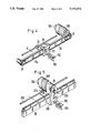
- FIG. 3 is a partially schematic, partially perspective view of the weft thread provision arrangement in accordance with this invention.
- FIG. 4 is a partial perspective view of an alternate embodiment employing a timing belt in the transport mechanism.
- FIG. 5 is a partial perspective view of a further embodiment employing a rack and pinion in the transport mechanism.
- FIG. 6 is a rear elevational view of yet another embodiment employing a linear motor in the transport mechanism.
- FIG. 7 is a front perspective view of the mechanism of FIG. 6.
- FIG. 8 is a flowchart associated with the programming of the computer of FIG. 3.
- FIG. 1 shows a pair of forwarding means 1 and 2 which are parallel endless chains extending perpendicularly to the plane o the drawing.
- Means 1 and 2 are provided with hooks 3 and 4 operating as holding means for holding weft thread 6.
- thread guides 5 segments of weft thread 6 are laid between these hooks.
- the weft threads are provided from spools 7 in creels (not illustrated) and led over a turning roller 8 located substantially midway above the laid weft threads.
- the thread guides 5 are moved in the direction of path arrow S from the initial position "a" over a central position "b" to the end position "c". There the thread guides are moved parallel to the forwarding means 2, whereby the threads can be laid around the hooks 4. Then the thread guides 7 are moved back into position "a”.
- the length of segment "d-e” is thus altered so that the in the travel from the left side to the middle, segment "d-e", already contains a segment of "a-b”.
- FIG. 2A, B and C illustrate the path and speed of thread guides 5 over the laying path S over time "t", as well as that of the thread take-off speed.
- FIG. 2 illustrates the path of thread guides 5 over the laying path S over time "t".
- the curve s. shows the conventional sinusoidal shape when the weft insert carriage is driven by a drive connected to the main shaft of the warp knitting machine. This path trajectory corresponds to the speed curve v o . Additionally, the curve f o is shows the weft thread takeoff speed, as provided by the arrangement of FIG. 1. These substantial speed oscillations give to corresponding strains on the weft thread.
- a motion path formula represented by such curve is freely selectable. If one chooses another path curve "s", there is thus provided a different characteristic velocity profile "v" for the speed of the weft insert carriage. This in turn leads to another characteristic curve "f” for the takeoff speed of the weft thread. While the motion path formula corresponding to curve s 1 corresponds to a protracted start, the motion formula in accordance with path characteristic curve s 2 shows the conditions pertaining to an accelerated start.
- the lower start speed of the weft insert carriage also corresponds to a lower initial speed of the weft thread. This is very desirable with thin and sensitive threads, since the threads are subjected to less strain at the start of the motion. In the last third of the travel path however, the thread speed is greater than f 0 .
- the curve s 2 is chosen in order to more rapidly traverse the segment shown from the left side to the center of FIG. 1 because a portion of the weft thread 6 is already provided in the segment "d-e". Since the weft insert carriage runs more slowly in the second half of the path, the thread takeoff speed in this segment is smaller than that shown in characteristic curve f 0 .
- s 3 is a nonsinusoidal path.
- v 0 , v 1 , v 2 and v 3 correspond to the velocities of the trajectories s 0 , s 1 s 2 and s 3 and in FIG. 2C, f 0 , f 1 , and f 2 correspond to the appropriate thread speeds for the foregoing trajectories s 0 , s 1 and 2 2 , respectively.
- the time segments on the ordinate each represent one rotation of the main shaft. For example, where there are 18 rotations of the main shaft corresponding to a single movement of the thread guide 5 between end points "a" and "c", then 18 weft threads are laid at the same time.
- FIG. 2 shows the motion path formula in the normal sinusoidal fashion, as well as one with a protracted (S 1 ), one with an accelerated path start (S 2 ) and one with a nonsinusoidal path (S 3 ).
- Other mathematically based motion formulae can also be considered which have a symmetric or asymmetric progression. Such motion path formulae are already well known.
- a brushless direct current motor which drives a ball screw linear actuator 10 on which the weft insert carriage 11 is moveable to and fro in the direction of arrow S.
- the weft insert carriage 11 carries the thread guides 5 below sled 12.
- Sled 12 is axially slidable on carriage 11 in the direction of double headed arrow X by means of a second servomotor 13.
- Sled 12 is reciprocated at the turnaround point of the travel path of carriage 11.
- a fixed weft insert carriage guide 14 extends parallel to the actuator 10 and slides through carriage 11.
- Servomotor 9 is controlled by the combined action of computer M with drive amplifier A.
- a data storage means S is provided to the computer.
- Storage means S may be 256 kb of RAM memory, although other size memories may be used depending upon the complexity of the programming and the desired precision of the control function.
- Computer M may be any computing device, including a microprocessor such as Intel type 80386.
- Utilizing data input means 15 which may, for example, be a keyboard, the parameters for the desired motion path formula may be entered. Via a selection input means 16, any one of several motion path formulae may be selected.
- a sensor 18 is utilized to read angular displacement data from the main shaft 17 of the warp knitting machine. These angular data include the number of rotations (this is reduced to the rotational speed) and the rotational angle (that is, the position). For this purpose, it is desirable to use a sensor having a pulse generator 19. The pulses are accumulated and converted by the computer M into position and speed data.
- Transducer 20 comprises a path distance measuring means 21 and a reference signal generator 22.
- the path distance measuring means further comprises a pulse generator 23, which produces pulses in proportion to the rotation of the ball screw linear actuator 10.
- Generator 23, in combination with computer M, enables determination of the position value assigned to the weft insert carriage 11.
- the reference signal generator 22 is activated when the weft insert carriage 11 reaches a predetermined end position.
- Generator 22 may be a proximity detector comprising an optical sensor, proximity switch or similar devices. This arrangement gives rise to a reference point for the path distance measured by the path distance measuring means 21. For example, a register in computer M can be reset to a predetermined count when generator 22 issues a pulse. Thereafter, this count can be decremented (or incremented) to indicate relative displacement from the reference point.
- the servomotor 9 is provided with a transducer 24 in the form of a tachometer generator for measuring the actual value of the motor speed.
- computer M derives data from the motion path formula from the storage means S with a speed predetermined by the number of rotations of the main shaft 17, wherein the starting point corresponds to the particular position of main shaft 17.
- the turning of the main shaft 17 may be used to provide target position values for weft insert carriage 11.
- These target values are compared with the actual position values, which are provided by means of the position transducer 20.
- the drive speed is either maintained or corrected.
- a proportional integral control loop can be employed to develop a target speed value.
- This target speed signal is thus provided via output 25 of computer M to amplifier A as a desired speed value.
- Amplifier A may be a voltage-controlled, variable frequency converter, which provides servomotor 9 via power lines 26 a potential at a variable frequency.
- the actual speed of the servomotor is determined by the actual value transducer 24 whose data is transmitted to amplifier A via feedback line 27. If the desired and actual values do not correspond with each other, for example if there is too heavy a load on the servomotor, this is corrected by amplifier A.
- the programming of computer can be in any appropriate language and, if desired, compiled for quick response.
- the exemplary flowchart of FIG. 8 shows an initializing routine where various computer registers are set to nominal operating parameter that determine the frequency of updating, the starting point of variables etc. Thereafter data input/output is accomplished. For example, any revised output signals can be transmitted at this time to amplifier A and servomotor 29. Also transducers 18 and 20 may be read, as well as control inputs from ports 15 and 16 Alternatively, input data can be handled by an interrupt handler that interrupts the routine program process to allow fresh data or operator input to be stored in memory before returning to routine processing. As indicated in the third program step, computer M updates the main shaft position based upon the receipt on any new pulses from transducer 19.
- the program uses the newly calculated shaft position to determined the target position for the carriage 11.
- the determination can be obtained from a lookup table or by a mathematical formula.
- the difference between the target and actual carriage position is used to calculate a target carriage speed, as described above.
- a second output 28 of computer M operates a second servomotor 13, which is only activated at the turnaround point of carriage 11.
- the weft insert carriage 111 is moved to and fro in the direction of arrow S by means of a timing belt 30.
- the timing belt is laid around a rotatable idler 31 and about a further roller 33 driven by servomotor 109.
- Sled 112 has a tail projecting beyond carriage 111 to a side opposite guides 105.
- a guide shelf 33 which fits between guide pegs 34 on sled 112.
- the shelf 33 can be moved to and fro in the direction of arrow X by means of mechanisms which are not illustrated; for example, by a conventional cam or lever or by means of a second servomotor.
- Servomotor 209 has a pinion 35 and is supported by weft insert carriage 211.
- Carriage 211 encircles a rack 36 that is adjacent to and engages pinion 35. Operation of servomotor 209 turns pinion 35 to engage rack 36 and produce a reactive force that moves carriage 211.
- the weft insert carriage 311 is integrated in the armature 37 of a servomotor 309, provided as a linear motor.
- Carriage 311 is a rectangular block with a rectangular passage holding inductors 43 and 44 on opposite sides of anchor 42.
- This linear motor is guided by guide sleeves 38 and 39 mounted on opposite hollows in carriage 311.
- Sleeves 38 and 39 ride on guide rods 40 and 41 mounted on opposite sides of and parallel to anchor 42.
- the linear motor action is provided by inductors 43 and 44 acting on anchor 42.
- the invention is described with respect to the continuous provision of weft threads 6 laid by thread guides 5 moving to and fro as a reversing weft thread magazine.
- the weft threads are grasped by grasping tongs attached to a weft insert carriage and are only laid in one direction between the thread forwarding means.
- Such laid weft thread segments are cut from the spool as soon as they are clamped onto a thread forwarding means.
Landscapes
- Engineering & Computer Science (AREA)
- Textile Engineering (AREA)
- Looms (AREA)
- Knitting Machines (AREA)
Applications Claiming Priority (2)
| Application Number | Priority Date | Filing Date | Title |
|---|---|---|---|
| DE3932184 | 1989-09-27 | ||
| DE3932184A DE3932184C2 (de) | 1989-09-27 | 1989-09-27 | Schußfadenzuführvorrichtung für das Schußfadenmagazin einer Kettenwirkmaschine |
Publications (1)
| Publication Number | Publication Date |
|---|---|
| US5111672A true US5111672A (en) | 1992-05-12 |
Family
ID=6390273
Family Applications (1)
| Application Number | Title | Priority Date | Filing Date |
|---|---|---|---|
| US07/588,654 Expired - Lifetime US5111672A (en) | 1989-09-27 | 1990-09-26 | Weft thread insertion arrangement |
Country Status (3)
| Country | Link |
|---|---|
| US (1) | US5111672A (enExample) |
| JP (1) | JPH03119158A (enExample) |
| DE (1) | DE3932184C2 (enExample) |
Cited By (10)
| Publication number | Priority date | Publication date | Assignee | Title |
|---|---|---|---|---|
| US5680777A (en) * | 1996-10-03 | 1997-10-28 | Zorini; Luigi Omodeo | Device for inserting alternately-interposed wefts on a crochet galloon machine for warp weaving, and article of manufacture thus obtained |
| US6176104B1 (en) * | 1998-12-23 | 2001-01-23 | Luigi Omodeo Zorini | Actuator device for the controlled movement of members in knitting machines |
| US20050198792A1 (en) * | 2004-03-11 | 2005-09-15 | Karl Mayer Malimo Textilmaschinenfabrik Gmbh | Process and apparatus for laying fiber bands of filaments |
| US20050284187A1 (en) * | 2004-06-29 | 2005-12-29 | Karl Mayer Textilmaschinenfabrik Gmbh | Guide bar drive in a knitting machine |
| EP1749913A1 (en) * | 2005-07-28 | 2007-02-07 | Officina Meccanica Trinca Colonel Silvio & Figlio Sergio S.n.c. | Device for moving a shuttle, for shuttle weaving machines |
| US20070033969A1 (en) * | 2003-06-19 | 2007-02-15 | Giuseppe Mele | Knitting machine |
| US20080091293A1 (en) * | 2006-10-16 | 2008-04-17 | Ebert Composites Corporation | 90 Degree Ply Placement System and Method |
| CN101892555A (zh) * | 2009-05-20 | 2010-11-24 | 利巴机械制造有限公司 | 用于敷设单向层的装置以及多轴向编织机 |
| US20140110016A1 (en) * | 2011-05-27 | 2014-04-24 | Mitsubishi Rayon Co., Ltd. | Loom and weaving method using the same |
| CN112064192A (zh) * | 2020-08-18 | 2020-12-11 | 福建杰嘉科技有限公司 | 一种针床及其使用该针床的纺织机 |
Families Citing this family (12)
| Publication number | Priority date | Publication date | Assignee | Title |
|---|---|---|---|---|
| DE19604422C2 (de) * | 1996-02-07 | 1999-11-11 | Malimo Maschinenbau | Antriebsvorrichtung für Arbeitselemente, insbesondere Mehrfachfadenführer, auf dem Schußwagen einer Kettenwirkmaschine |
| DE19610671B4 (de) * | 1996-02-07 | 2005-09-29 | Malimo-Maschinenbau Gmbh | Verfahren zum Einhängen von Schußfadenscharen in die Haken der Transportketten einer Kettenwirk- oder Nähwirkmaschine |
| DE19726831C5 (de) * | 1997-06-24 | 2005-02-17 | Liba Maschinenfabrik Gmbh | Multiaxial-Maschine mit Portalaufbau |
| DE19739942A1 (de) * | 1997-09-11 | 1999-03-18 | Saertex Wagener Gmbh & Co Kg | Vorrichtung und Verfahren zur Herstellung von Textilgelegen |
| DE19742721C1 (de) * | 1997-09-26 | 1999-06-02 | Malimo Maschinenbau | Verfahren und Vorrichtung zum Legen und Einhängen von Schußfadenscharen |
| DE19802994C1 (de) * | 1998-01-28 | 1999-05-20 | Mayer Malimo Textilmaschf | Verfahren und Vorrichtung zum Legen von einander unter verschiedenen Winkeln kreuzenden Diagonalfadenlagen |
| DE19816440C1 (de) * | 1998-04-14 | 1999-07-08 | Liba Maschf | Verfahren und Kettenwirkmaschine zum Herstellen von Wirkware mit frei wählbarem Schußfaden-Musterrapport |
| DE10021341A1 (de) * | 2000-05-02 | 2001-11-15 | Fraunhofer Ges Forschung | Verfahren und Vorrichtung zur Bildung von, insbesondere mehrschichtigen Schußfäden-Verlegungen multiaxial orientierter Fadengelege und Fadenleger hierfür, sowie mehrschichtiges Schußfädengelege |
| DE10049280B4 (de) * | 2000-09-28 | 2004-07-01 | Karl Mayer Malimo Textilmaschinenfabrik Gmbh | Verfahren zum Herstellen von Wirkware mit in unterschiedlicher Dichte angeordneten Schussfäden |
| FR2832738B1 (fr) * | 2001-11-27 | 2004-02-13 | Eads Launch Vehicles | Dispositif de tramage pour la realisation d'armatures textiles epaisses et armatures ainsi obtenues |
| CN103061031B (zh) * | 2013-01-28 | 2014-04-02 | 常州市第八纺织机械有限公司 | 纱线铺纬器 |
| EP4467697A1 (de) * | 2023-05-24 | 2024-11-27 | KARL MAYER Technische Textilien GmbH | Kettenwirkmaschine zum herstellen von wirkware mit frei wählbarem schussfaden-musterrapport und verfahren zum herstellen von wirkware mit frei wählbarem schussfaden-musterrapport |
Citations (10)
| Publication number | Priority date | Publication date | Assignee | Title |
|---|---|---|---|---|
| US3593394A (en) * | 1969-11-05 | 1971-07-20 | Deering Milliken Res Corp | Apparatus having improved control means for producing nonwoven fabrics |
| DE2519762A1 (de) * | 1975-05-02 | 1976-11-11 | Schlafhorst & Co W | Antrieb fuer den fadenleger einer wirkmaschine |
| US4068357A (en) * | 1976-12-27 | 1978-01-17 | Mcdonnell Douglas Corporation | Method and apparatus for fabricating open weave scrim cloth |
| US4395888A (en) * | 1980-10-25 | 1983-08-02 | Karl Mayer Textilmaschinenfabrik Gmbh | Controlled thread guides for a weft thread magazine |
| US4487039A (en) * | 1982-09-21 | 1984-12-11 | Karl Mayer Textilmaschinenfabrik Gmbh | Weft magazine arrangement for warp knitting machines |
| US4528631A (en) * | 1982-05-21 | 1985-07-09 | Karl Mayer Testilmaschinenfabrik Gmbh | Process for the control of warping speed and a direct warping machine for carrying out this process |
| US4703631A (en) * | 1984-12-28 | 1987-11-03 | Karl Mayer Textilmaschinenfabrik | Warp knitting machine |
| US4761973A (en) * | 1987-05-08 | 1988-08-09 | Richard Gangi | Warp knitting/crochet warp knitting machine |
| US4793158A (en) * | 1986-12-05 | 1988-12-27 | Liba Maschinenfabrik Gmbh | Process and mechanism for feeding weft threads for warp knitting machines with longitudinal conveyors and rakes |
| JPH0297934A (ja) * | 1988-10-04 | 1990-04-10 | Canon Inc | 原稿読取装置 |
Family Cites Families (3)
| Publication number | Priority date | Publication date | Assignee | Title |
|---|---|---|---|---|
| JPS5413551B2 (enExample) * | 1973-04-26 | 1979-05-31 | ||
| DE2451731A1 (de) * | 1974-10-31 | 1976-05-06 | Schlafhorst & Co W | Antrieb fuer den fadenfuehrer einer wirkmaschine |
| DD130263A1 (de) * | 1977-03-31 | 1978-03-15 | Dietrich Karl Heinz | Vorrichtung an naehwirkmaschinen |
-
1989
- 1989-09-27 DE DE3932184A patent/DE3932184C2/de not_active Expired - Fee Related
-
1990
- 1990-09-26 JP JP2258792A patent/JPH03119158A/ja active Granted
- 1990-09-26 US US07/588,654 patent/US5111672A/en not_active Expired - Lifetime
Patent Citations (10)
| Publication number | Priority date | Publication date | Assignee | Title |
|---|---|---|---|---|
| US3593394A (en) * | 1969-11-05 | 1971-07-20 | Deering Milliken Res Corp | Apparatus having improved control means for producing nonwoven fabrics |
| DE2519762A1 (de) * | 1975-05-02 | 1976-11-11 | Schlafhorst & Co W | Antrieb fuer den fadenleger einer wirkmaschine |
| US4068357A (en) * | 1976-12-27 | 1978-01-17 | Mcdonnell Douglas Corporation | Method and apparatus for fabricating open weave scrim cloth |
| US4395888A (en) * | 1980-10-25 | 1983-08-02 | Karl Mayer Textilmaschinenfabrik Gmbh | Controlled thread guides for a weft thread magazine |
| US4528631A (en) * | 1982-05-21 | 1985-07-09 | Karl Mayer Testilmaschinenfabrik Gmbh | Process for the control of warping speed and a direct warping machine for carrying out this process |
| US4487039A (en) * | 1982-09-21 | 1984-12-11 | Karl Mayer Textilmaschinenfabrik Gmbh | Weft magazine arrangement for warp knitting machines |
| US4703631A (en) * | 1984-12-28 | 1987-11-03 | Karl Mayer Textilmaschinenfabrik | Warp knitting machine |
| US4793158A (en) * | 1986-12-05 | 1988-12-27 | Liba Maschinenfabrik Gmbh | Process and mechanism for feeding weft threads for warp knitting machines with longitudinal conveyors and rakes |
| US4761973A (en) * | 1987-05-08 | 1988-08-09 | Richard Gangi | Warp knitting/crochet warp knitting machine |
| JPH0297934A (ja) * | 1988-10-04 | 1990-04-10 | Canon Inc | 原稿読取装置 |
Cited By (15)
| Publication number | Priority date | Publication date | Assignee | Title |
|---|---|---|---|---|
| US5680777A (en) * | 1996-10-03 | 1997-10-28 | Zorini; Luigi Omodeo | Device for inserting alternately-interposed wefts on a crochet galloon machine for warp weaving, and article of manufacture thus obtained |
| US6176104B1 (en) * | 1998-12-23 | 2001-01-23 | Luigi Omodeo Zorini | Actuator device for the controlled movement of members in knitting machines |
| US7533545B2 (en) * | 2003-06-19 | 2009-05-19 | Textilma Ag | Knitting machine |
| US20070033969A1 (en) * | 2003-06-19 | 2007-02-15 | Giuseppe Mele | Knitting machine |
| US7120976B2 (en) * | 2004-03-11 | 2006-10-17 | Karl Mayer Malimo Textilmaschinenfabrik Gmbh | Process and apparatus for laying fiber bands of filaments |
| US20050198792A1 (en) * | 2004-03-11 | 2005-09-15 | Karl Mayer Malimo Textilmaschinenfabrik Gmbh | Process and apparatus for laying fiber bands of filaments |
| US20050284187A1 (en) * | 2004-06-29 | 2005-12-29 | Karl Mayer Textilmaschinenfabrik Gmbh | Guide bar drive in a knitting machine |
| US7332836B2 (en) | 2004-06-29 | 2008-02-19 | Karl Mayer Testilmaschinenfabrik Gmbh | Guide bar drive in a knitting machine |
| EP1749913A1 (en) * | 2005-07-28 | 2007-02-07 | Officina Meccanica Trinca Colonel Silvio & Figlio Sergio S.n.c. | Device for moving a shuttle, for shuttle weaving machines |
| US20080091293A1 (en) * | 2006-10-16 | 2008-04-17 | Ebert Composites Corporation | 90 Degree Ply Placement System and Method |
| US8131395B2 (en) * | 2006-10-16 | 2012-03-06 | Ebert Composites Corporation | 90 degree ply placement system and method |
| CN101892555A (zh) * | 2009-05-20 | 2010-11-24 | 利巴机械制造有限公司 | 用于敷设单向层的装置以及多轴向编织机 |
| US20140110016A1 (en) * | 2011-05-27 | 2014-04-24 | Mitsubishi Rayon Co., Ltd. | Loom and weaving method using the same |
| US9074307B2 (en) * | 2011-05-27 | 2015-07-07 | Mitsubishi Rayon Co., Ltd. | Loom and weaving method using the same |
| CN112064192A (zh) * | 2020-08-18 | 2020-12-11 | 福建杰嘉科技有限公司 | 一种针床及其使用该针床的纺织机 |
Also Published As
| Publication number | Publication date |
|---|---|
| JPH0368144B2 (enExample) | 1991-10-25 |
| DE3932184C1 (enExample) | 1991-01-31 |
| DE3932184C2 (de) | 1996-06-20 |
| JPH03119158A (ja) | 1991-05-21 |
Similar Documents
| Publication | Publication Date | Title |
|---|---|---|
| US5111672A (en) | Weft thread insertion arrangement | |
| EP0999992B1 (de) | Verfahren und changiereinrichtung zum verlegen eines fadens | |
| CN1217839C (zh) | 一根连续送入的纱线的卷绕方法和装置 | |
| FR2376057A1 (fr) | Procede et dispositif pour le reglage du deroulage d'un fil textile | |
| CA1184628A (en) | Electronic glassware handling | |
| US4165665A (en) | Web cutting apparatus | |
| US4235070A (en) | Wire stranding machine and control means therefor | |
| CN1332867C (zh) | 横动控制装置 | |
| US20040021031A1 (en) | Device for traversing a flexible linear product for spooling | |
| US5785265A (en) | Winding machine for a continuously arriving yarn | |
| US6241177B1 (en) | Method and apparatus for winding a continuously advancing yarn | |
| KR0120935B1 (ko) | 경사 비임 구동용 장치 | |
| EP0231618B1 (en) | Web-laying | |
| JPS6097169A (ja) | 糸の巻取り方法及びその巻取り装置 | |
| CN105722776B (zh) | 横动单元和用于控制横动单元的方法 | |
| CA1041197A (en) | Control system for controlling translational speed of carriage with respect to rotational speed of mandrel | |
| US4236373A (en) | Traverse control system | |
| JP3335246B2 (ja) | 線条体用リール巻取機のトラバース制御装置及びその制御方法 | |
| JPS604017A (ja) | 射出成形機の運転条件設定方法 | |
| GB2269826A (en) | Drive means for operating working elements of a knitting machine | |
| SU861435A1 (ru) | Устройство дл автоматического регулировани времени обработки материала в технологической машине | |
| SU821576A1 (ru) | Устройство дл регулировани пОдАчи НиТи | |
| KR920000275B1 (ko) | 측장량 가변장치 | |
| JP4470338B2 (ja) | 糸条巻取機のトラバース制御方法 | |
| RU2070158C1 (ru) | Способ регулирования положения точки смены направления пряжи и аппаратура для его осуществления |
Legal Events
| Date | Code | Title | Description |
|---|---|---|---|
| AS | Assignment |
Owner name: KARL MAYER TEXTILMASCHINENFABRIK GMBH, GERMANY Free format text: ASSIGNMENT OF ASSIGNORS INTEREST.;ASSIGNORS:GILLE, FRIEDRICH;NAUMANN, ROLF;BERGMANN, GERHARD;REEL/FRAME:005455/0850 Effective date: 19900914 |
|
| STCF | Information on status: patent grant |
Free format text: PATENTED CASE |
|
| FEPP | Fee payment procedure |
Free format text: PAYOR NUMBER ASSIGNED (ORIGINAL EVENT CODE: ASPN); ENTITY STATUS OF PATENT OWNER: LARGE ENTITY |
|
| FPAY | Fee payment |
Year of fee payment: 4 |
|
| FPAY | Fee payment |
Year of fee payment: 8 |
|
| FEPP | Fee payment procedure |
Free format text: PAYER NUMBER DE-ASSIGNED (ORIGINAL EVENT CODE: RMPN); ENTITY STATUS OF PATENT OWNER: LARGE ENTITY Free format text: PAYOR NUMBER ASSIGNED (ORIGINAL EVENT CODE: ASPN); ENTITY STATUS OF PATENT OWNER: LARGE ENTITY |
|
| FPAY | Fee payment |
Year of fee payment: 12 |